Article

Dynamic Performance Analysis of Gas Film Floating Ring Seals Based on the Reynolds–Bernoulli Small-Perturbation Model

Research Center of Fluid Sealing Technology, College of Mechanical and Electrical Engineering, Beijing University of Chemical Technology, Beijing 100029, China
*
Author to whom correspondence should be addressed.
Machines 2024, 12(12), 860; https://doi.org/10.3390/machines12120860
Submission received: 26 October 2024 / Revised: 20 November 2024 / Accepted: 26 November 2024 / Published: 27 November 2024
(This article belongs to the Section Machine Design and Theory)

Abstract

:
Gas film floating ring seals are extensively utilized in aircraft engines, and precise analysis of gas film performance is crucial for ensuring reliable seal design. For this reason, this paper proposes the Reynolds–Bernoulli small-perturbation (RBSP) model to analyze the performance of the gas film based on the conservation of mechanical energy. Through experimental verification and comparison with other analytical models, the results of the RBSP model calculations are both reliable and more broadly applicable. Analyses using the finite element method revealed that the differential pressure effect of Poiseuille flow and the dynamic pressure effect of Couette flow are the primary factors enabling the floating ring to overcome resistance and establish a non-contact seal. Additionally, an appropriate sealing clearance and an increased width of the floating ring could significantly enhance the dynamic performance of the seal. The research findings offer a dependable performance analysis method for designers of gas film floating ring seals.

1. Introduction

The floating ring seal is a combination seal that features a small radial clearance as the primary sealing mechanism and axial contact as the secondary sealing mechanism [1]. Due to the wedge clearance between the floating ring and the rotor, the media flow creates a Poiseuille flow pressure difference. Simultaneously, the dynamic pressure effect from the Couette flow, caused by the rotor’s rotation, enables the floating ring to overcome the friction of the secondary sealing surface as well as its own weight. This allows the rotor and the floating ring to maintain concentric alignment, resulting in a non-contact seal. Consequently, this design is particularly well-suited for extreme operating conditions, such as those found in compressors, high-speed helicopter engines, and hydrogen turbopump seals in liquid rocket engines.
The sealing clearance is a key parameter of the gas film floating ring seal. Maintaining a stable and appropriate sealing clearance is crucial for ensuring the safety and reliability of the sealing state during operation. By selecting appropriate sealing materials and structural parameters, researchers have achieved stable control of the sealing gap [2]. However, due to the limitations of the gas film performance analysis method, further in-depth research is required to determine the optimal value of the sealing gap concerning its dynamic performance. Due to the significant axial flow velocity of the floating ring seal, the pressure loss at the inlet boundary cannot be overlooked. Current calculation methods fail to accurately depict the pressure distribution of the film flow, which complicates the precise analysis of the seal’s dynamic performance. Therefore, it is crucial to establish a reliable and accurate method for analyzing the performance of the gas film.
Scholars have conducted numerous studies on the performance of floating ring seals using various methodologies. Zhang [3] derived the leakage equation for floating ring seals from the Reynolds equation. Chen [4] modified the empirical leakage equation for floating ring seals through finite element numerical simulation. Hu [5,6] and Anbarsooz [7] analyzed the leakage characteristics of floating ring seals based on the Reynolds equation. Duan [8] employed the Bulk-Flow model to examine the overall flow of the seal. Wang [9] examines the analysis of sealing leakage characteristics in relation to viscosity effects. Tokunaga [10] and Song [11] employ the inlet pressure loss calculation method proposed by Hori [12] for their analysis. The results indicated that leakage increased with the rise in eccentricity, radial clearance, and pressure drop, while the effect of the axis’s rotation speed was negligible. However, due to the substantial errors in the calculation method for the air film floating ring seal mentioned above, Fukui et al. [13] investigated turbulent lubrication theory and proposed a correction factor for the Reynolds equation. Their research indicates that employing the corrected Reynolds equation for calculations can enhance both accuracy and efficiency. The studies mentioned above provide valuable insights for the analysis of thin film flow based on the conservation of mechanical energy, as proposed in this paper.
In order to ensure safe and reliable sealing operations, the study of seal dynamic performance has become a top priority. As early as 1978, scholars began researching the dynamic characteristics of floating ring seals. They proposed that to prevent the floating ring from making contact with the shaft, it is essential to consider the motion laws of the floating ring under the influence of fluid forces, allowing the floating ring to follow the movement of the shaft. To enhance the dynamic performance of the floating ring seal, researchers have employed finite element methods to analyze its dynamic characteristics and have conducted comprehensive studies on the flow field characteristics [14]. The research results indicate that the dynamic performance of sealing improves to some extent with an increase in sealing width. Additionally, micro-textures can effectively enhance the performance of floating ring seals; however, they may also lead to increased leakage [15,16]. In 2016, Mariot [17] conducted the first experimental validation of the numerical analysis model for the floating ring seal. Subsequently, Joon Hwan [18] performed related dynamic tests, which showed good agreement with the theoretical comparisons. The development of an accurate thin film flow analysis method not only provides a reliable theoretical foundation for seal performance analysis but also informs the precise design of the seal.
The current calculation methods struggle to accurately simulate the gas film pressure distribution, and the dynamic analysis methods for floating ring seals are not yet fully developed. This results in high experimental and time costs, which hinder the rapid advancement of floating ring seals. Based on previous research and considering the differences in circumferential pressure distribution of the gas film due to wedge clearance, this paper presents a solution method for gas film pressure. This method is derived from the conservation of mechanical energy by associating Reynolds’ equation with Bernoulli’s equation. On this basis, the dynamic performance analysis method of the gas film is derived using the small-perturbation method. The accuracy and reliability of this analysis method are validated through experiments and compared with the results from Mihai [19]. In this article, the RBSP model is further employed to investigate the working principle of the floating-ring seal and to analyze its sealing performance.

2. RBSP Model

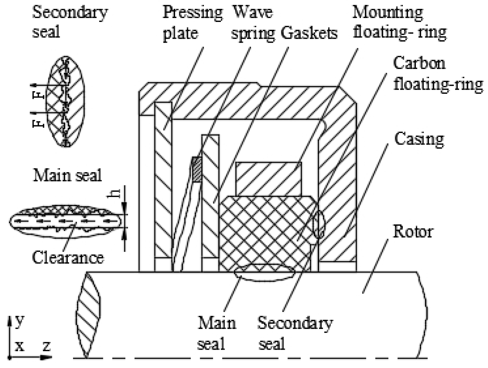
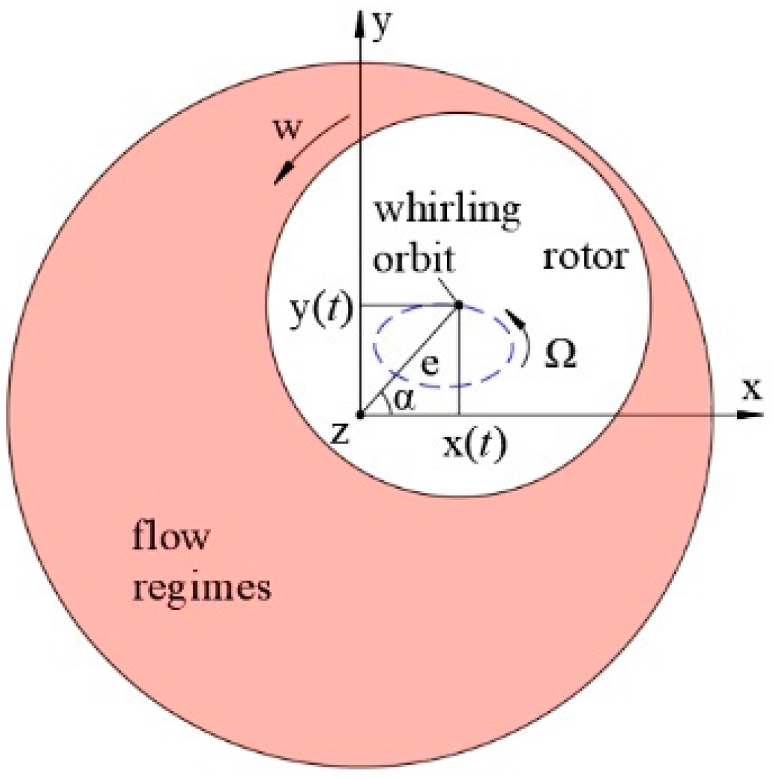
2.1. Structure and Working Principle

The floating-ring seal structure, illustrated in Figure 1, comprises a carbon floating ring, a mounting floating ring, a gasket, a wave spring, a pressing plate, and a casing. The carbon floating ring and the mounting floating ring are engineered to create an interference fit, which forms the floating ring. The wave spring applies pressure to the floating ring, establishing a primary clearance seal with the rotor and a secondary contact seal with the casing.
As illustrated in Figure 2, there is an eccentricity between the floating ring and the rotor, resulting in a wedge-shaped clearance. The axial flow of the medium creates a differential pressure effect, while the circumferential flow generates a dynamic pressure effect. Consequently, the floating ring can counteract gravity and the friction of the secondary sealing surface, allowing the floating ring and the rotor to align concentrically, thereby establishing a non-contact dynamic pressure seal. Relative eccentricity is defined as the ratio of eccentricity to the seal radial clearance:
ω = e / C r
where e is the eccentricity, e = x 1 2 + y 1 2 , mm; Cr is the sealing radial clearance, Cr = R − r, mm.
The non-contact critical gas film thickness is denoted as h c . When the minimum gas film thickness h min = C r e is greater than h c , the floating ring forms a non-contact seal with the rotor. The non-contact critical gas film thickness h c is defined as
h c = 3 σ
where σ represents the combined standard deviation of the contact surfaces, and σ 1 and σ 2 denote the standard deviations of the surface roughness at the contact locations of the carbon floating ring and casing, respectively, then σ = σ 1 2 + σ 2 2 .

2.2. Reynolds–Bernoulli Gas Film Control Equation

The Reynolds equation, derived from the equations of motion and continuity, serves as the fundamental control equation for the gas film floating ring seal. The pressure distribution of the gas film is determined by solving the Reynolds equation within the flow regimes. The Reynolds equation is expressed in the Cartesian coordinate system [3]:
x ( ρ h 3 μ P x ) + z ( ρ h 3 μ P z ) = 6 U ( ρ h ) x + 12 ( ρ h ) t
where P is the gas film pressure, ρ is the density at each position of the gas film, t is the time, U is the velocity, h is the gas film thickness, and μ is the air viscosity.
The flow field of the floating ring seal comprises Poiseuille flow resulting from an axial pressure drop and circumferential Couette flow induced by rotor rotation [13]. The axial flow velocity of the film flow is expressed as follows:
u p = h 2 12 μ d P d z
Due to the significant clearance in the gas film floating ring seal and the pressure drop, a substantial axial flow velocity is generated. This results in the conversion of pressure energy from the high-pressure cavity into kinetic energy, leading to pressure loss. The presence of eccentric working conditions causes considerable variation in inlet pressure loss across different film thicknesses of the gas film. The pressure distribution of the gas film under actual working conditions is derived by applying the Bernoulli equation to calculate the pressure loss at the boundary of the thin film flow. The association of the Reynolds equation with the Bernoulli equation is referred to as the Reynolds–Bernoulli (R-B) gas film control equation. Neglecting the effects of gravity, the boundary pressure of the film flow is as follows:
{ P 1 = P 11 ( 1 2 + ξ 1 2 ) u p 2 ρ P 2 = P 22 u p = P z h 2 12 μ
where up represents the Poiseuille flow rate due to pressure in the clearance, h denotes the gas film thickness, P 1 indicates the film inflow port pressure, P 2 refers to the film flow downstream pressure, P 11 signifies the high-pressure side chamber pressure, P 22 represents the low-pressure side chamber pressure, and ξ 1 is the inlet pressure loss coefficient, which is taken as 0.5.

2.3. Dynamic Characteristic Equations Based on the Small-Perturbation Method

The dynamic Reynolds equation is derived by introducing a perturbation term to the steady-state Reynolds equation:
x ( ρ m h m 3 μ P m x ) + z ( ρ m h m 3 μ P m z ) = 6 U ( ρ m h m ) x + 12 ( ρ m h m ) t
The dynamic variables P m , h m , ρ m are combinations of stabilization and perturbation terms. By substituting the decomposed physical quantities into the dynamic Reynolds equation, one can solve for both the time-independent steady-state properties and the time-dependent dynamic properties.
The position of the rotor and the floating ring is illustrated in Figure 3. The rotor exhibits a whirl motion relative to the floating ring, characterized by an eccentricity e and a whirl frequency Ω . Normal mode theory is utilized to describe the perturbation displacements and velocities of the rotor axes in the orthogonal coordinate plane:
x ( t ) = | Δ x | e i v t y ( t ) = | Δ y | e i v t x ˙ ( t ) = i v | Δ x | e i v t = i v x ( t ) y ˙ ( t ) = i v | Δ y | e i v t = i v y ( t )
By expanding the pressure expression using Taylor’s formula and retaining a small amount of first-order perturbation, the perturbation gas film pressure becomes a function of both perturbation displacement and perturbation velocity. We can derive the following:
P m = P m , o + P m
P m = P m x | 0 x ( t ) + P m y | 0 y ( t ) + P m x ˙ | 0 x ˙ ( t ) + P m y ˙ | 0 y ˙ ( t )
where Pm is the dynamic film pressure, Pm,0 is the steady film pressure, and P m is the perturbation film pressure (Pa). The perturbation pressure can be expressed using the following equation:
p x r = P m x | 0 p y r =   P m y | 0 p x i = v P m x ˙ | 0 p y i = v P m y ˙ | 0
Equation (9) can be expressed as follows:
P m = ( p x r + i p x i ) x ( t ) + ( p y r + i p y i ) y ( t )
The relationship between the component forces in the x and y directions and the pressure Pm can be expressed in polar coordinates as follows:
{ F x = 0 l 0 2 π P m R 0 cos θ d θ d z F y = 0 l 0 2 π P m R 0 sin θ d θ d z
By substituting Equations (8) and (11) into Equation (12) and subtracting the stabilizing term, the following expression for the excitation force is derived:
F x = 0 l 0 2 π [ p x r x ( t ) + p y r y ( t ) ] R 0 cos θ d θ d z + 0 l 0 2 π 1 v [ p x i x ˙ ( t ) + p y i y ˙ ( t ) ] R 0 cos θ d θ d z
F y = 0 l 0 2 π [ p x r x ( t ) + p y r y ( t ) ] R 0 sin θ d θ d z + 0 l 0 2 π 1 v [ p x i x ˙ ( t ) + p y i y ˙ ( t ) ] R 0 sin θ d θ d z
Based on the theory of small-perturbation method, the gas film excitation forces, F x and F y , can be expressed linearly in terms of the gas film dynamic characteristic coefficients and small perturbation quantities as follows:
[ F x F y ] = [ K x x K x y K y x K y y ] [ X Y ] + [ C x x C x y C y x C y y ] [ X ˙ Y ˙ ]
where F x and F y represent the fluid excitation forces along the x and y axes, respectively, caused by changes in clearance. Kxx, Kyy and Kxy, Kyx denote the direct stiffness coefficient and cross stiffness coefficient of the gas film, respectively. Cxx, Cyy and Cxy, Cyx refer to the direct damping coefficient and cross damping coefficient of the gas film, respectively. X and Y indicate the rotor whirl motion displacements in the x and y directions, while X ˙ and Y ˙ represent the rotor whirl motion speeds in the x and y directions.
According to the definition, by comparing Equations (13)–(15), the gas film stiffness and damping can be determined as follows:
[ K x x K x y K y x K y y ] = 0 l 0 2 π [ p x r cos θ p y r cos θ p x r sin θ p y r sin θ ] R 0 d θ d z
[ C x x C x y C y x C y y ] = 1 v 0 l 0 2 π [ p x i cos θ p y i cos θ p x i sin θ p y i sin θ ] R 0 d θ d z

2.4. Dynamic Pressure Control Equations

The steady-state thickness of the gas film can be expressed as
h m , 0 = C r e m , 0 cos ( θ α )
The expression for the gas film dynamic film thickness is
h m = h m , 0 + h m = C r ( e m , 0 + x ( t ) cos α + y ( t ) sin α ) cos ( θ α y ( t ) cos α x ( t ) sin α e m , 0 )
Under perturbation, the perturbed film thickness can be approximated by subtracting Equation (18) from Equation (19) and omitting higher-order small quantities:
h m = x ( t ) cos θ y ( t ) sin θ
where em,0 represents the steady-state eccentricity distance, mm; α denotes the steady-state eccentricity angle, rad; C r indicates the radial clearance of the floating ring seal under working conditions, mm; and h m refers to the dynamic film thickness, mm.
The change in gas density is proportional to the magnitude of pressure as the film thickness varies. Therefore, the dynamic density of the fluid film can be expressed as follows:
ρ m = ρ m , 0 + ρ m = M R T ( P m , 0 + P m )
where ρm, ρm,0, and ρ m represent the dynamic, steady-state, and perturbation gas densities, respectively; M denotes the average molar mass of the gas; R is the molar gas constant; and T is the operating temperature.
Bring Equations (8), (19), and (21) into Equation (6) and expand. Ignore the small quantities above the second order, and then subtract the stability term. The micro-perturbation equation can be obtained:
      x [ ( ρ m , 0 h m , 0 3 μ P m x ) + ( M P m h m , 0 3 R T μ P m , 0 x ) + ( 3 ρ m , 0 h m , 0 2 h m μ P m , 0 x ) ] + z [ ( ρ m , 0 h m , 0 3 μ P m z ) + ( M P m h m , 0 3 R T μ P m , 0 x ) + ( 3 ρ m , 0 h m , 0 2 h m μ P m , 0 z ) ] = 6 U x ( ρ m , 0 h m + M P m h m , 0 R T ) + 12 t ( ρ m , 0 h + M P m h m , 0 R T )
Then, substitute Equations (11) and (20) into Equation (22) and take the derivative of the resulting equation. Since the real part of the complex equation is equal to the real part, and the imaginary part is equal to the imaginary part, we can derive the perturbed Reynolds equation in the x and y directions. Here, ν represents the excitation angular frequency:
x [ ρ m , 0 h m , 0 3 μ p x r x + M p x r h m , 0 3 R T μ P m , 0 x cos θ 3 ρ m , 0 h m , 0 2 μ P m , 0 x ] + z [ ρ m , 0 h m , 0 3 μ p x r z + M p x r h m , 0 3 R T μ P m , 0 z cos θ 3 ρ m , 0 h m , 0 2 μ P m , 0 z ] = 6 U x [ ρ m , 0 cos θ + M p x r h m , 0 R T ] 12 ν ( M p x i h m , 0 R T )
x [ ρ m , 0 h m , 0 3 μ p x i x + M p x i h m , 0 3 R T μ P m , 0 x ] + z [ ρ m , 0 h m , 0 3 μ p x i z + M p x i h m , 0 3 R T μ P m , 0 z ] = 6 U x [ M p x i h m , 0 R T ] + 12 ν ( M p x r h m , 0 R T ρ m , 0 cos θ )
x [ ρ m , 0 h m , 0 3 μ p y r x + M p y r h m , 0 3 R T μ P m , 0 x sin θ 3 ρ m , 0 h m , 0 2 μ P m , 0 x ] + z [ ρ m , 0 h m , 0 3 μ p y r z + M p y r h m , 0 3 R T μ P m , 0 z sin θ 3 ρ m , 0 h m , 0 2 μ P m , 0 z ] = 6 U x [ ρ m , 0 sin θ + M p y r h m , 0 R T ] 12 ν ( M p y i h m , 0 R T )
x [ ρ m , 0 h m , 0 3 μ p y i x + M p y i h m , 0 3 R T μ P m , 0 x ] + z [ ρ m , 0 h m , 0 3 μ p y i z + M p y i h m , 0 3 R T μ P m , 0 z ] = 6 U x [ M p y i h m , 0 R T ] + 12 ν ( M p y r h m , 0 R T ρ m , 0 sin θ )

2.5. Dynamic Boundary Conditions Based on the R-B Equation

Compared to a conventional dynamic pressure seal, the floating ring seal features a larger clearance and higher flow velocity, resulting in a more pronounced boundary pressure loss effect. Unlike previous studies, this paper utilizes the Reynolds–Bernoulli equation to derive the boundary conditions for gas film inlet pressure perturbations. The axial dynamic flow rate induced by Poiseuille flow is decomposed into a steady-state flow rate and a perturbation flow rate:
u p , m = u p + u p = h m 2 12 μ d P m d z
By substituting Equations (8) and (19) into Equation (27), subtracting the stabilizing term, and omitting higher-order small quantities, we can take the derivative of the resulting equation to obtain the velocity of the perturbation as follows:
{ u p x r = 2 h m , 0 cos θ 12 μ d P m , 0 d z h m , 0 2 12 μ d P x r d z u p x i = h m , 0 2 12 μ d P x i d z u p y r = 2 h m , 0 sin θ 12 μ d P m , 0 d z h m , 0 2 12 μ d P y r d z u p y i = h m , 0 2 12 μ d P y i d z
The boundary dynamic pressure is expressed by the following equation:
P 1 , m = P 11 3 4 u p , m 2 ρ m
By bringing Equations (21) and (27) into Equation (29), subtracting the stabilizing term, and omitting higher-order small quantities, the perturbation pressure boundary condition is derived as follows:
P m = 3 4 ( 2 u p u p ρ m , 0 + u p 2 ρ m )
Derivative operations are applied to Equation (30), and the gas film perturbation pressure boundary conditions are derived by incorporating the perturbation velocity as follows:
{ P x r = 3 4 ( 2 u p u p x r ρ m , 0 + u p 2 M P x r R T ) ,   P y r = 3 4 ( 2 u p u p y r ρ m , 0 + u p 2 M P y r R T ) P x i = 3 4 ( 2 u p u p x i ρ m , 0 + u p 2 M P x i R T ) ,   P y i = 3 4 ( 2 u p u p y i ρ m , 0 + u p 2 M P y i R T )

3. Analytical Models and Calculations

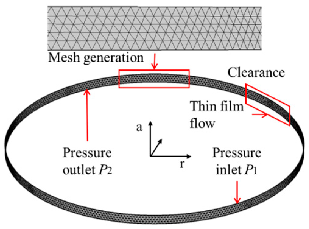
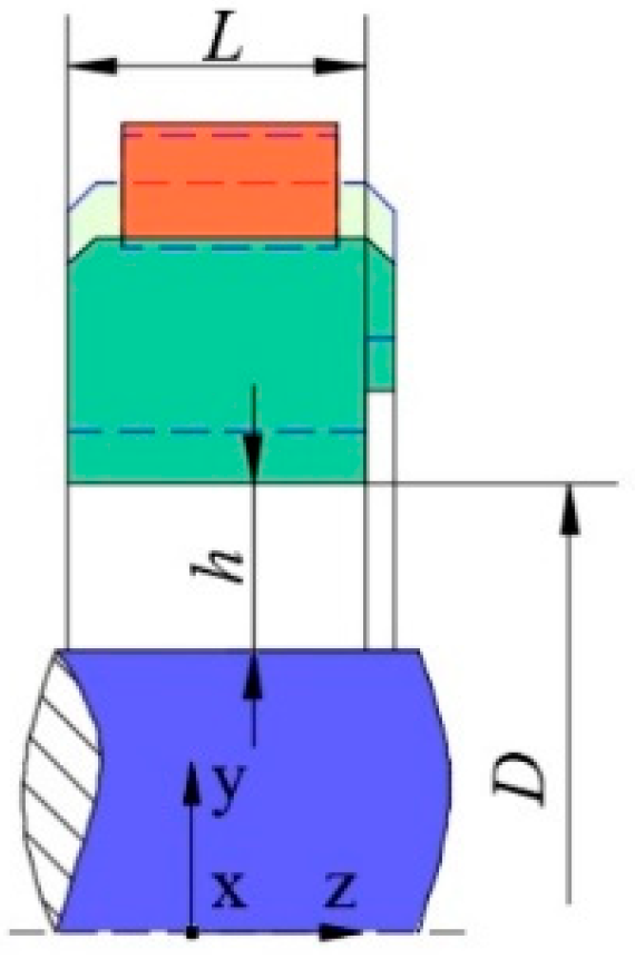
3.1. Analytical Modeling

Based on the control equation of the R-B gas film and the derived dynamic Reynolds equation, Comsol finite element analysis software was employed to develop a model for analyzing the characteristics of film flow, as illustrated in Figure 4. Equation (5) represents the pressure boundary condition for the steady-state gas film. Equation (31) defines the boundary pressure condition on the high-pressure side of the dynamic gas film, while the perturbation pressure on the low-pressure side is set to 0 Pa. The pressure and velocity distributions of the film flow are obtained by solving the aforementioned equations within the basin, and the dynamic characteristic coefficient of the film can be determined by integrating the dynamic pressure.
The structural model analyzed by Mihai [19] serves as an example, with structural dimensions D = 90.58 mm, C r = 30   μ m , h c = 2.1   μ m , and L = 4 mm. The geometry of the floating ring seal is illustrated in Figure 5. The working medium is air, the operating conditions are P11 = 900 kPa, P22 = 300 kPa, the operating temperature is 300 °C, the operating speed is 43,000 rpm, and the attitude angle is α = 0 ° .
The model is constructed using a triangular mesh, and the results of the mesh independence validation are presented in Table 1. Ultimately, the fluid domain consists of 1776 cells, with a minimum cell mass of 0.7. The mesh configuration satisfies the requirements for computational accuracy.

3.2. Analysis of Calculation Results

The steady-state pressure distribution, based on the R-B gas film control equation and solved for various eccentricities, is illustrated in Figure 6. When the eccentricity is small, the gas film pressure exhibits a uniform circular distribution, and the flow is primarily Poiseuille flow induced by the axial pressure drop. Distinct from the previous calculations, an increase in eccentricity resulted in a noticeable high pressure on one side of the gas film, while the opposite side exhibited a low-pressure phenomenon. As the eccentricity continued to rise, the dynamic pressure effects of the gas film disrupted the Poiseuille flow pressure distribution, leading to a significant non-uniform distribution of the gas film. Figure 7 illustrates the dynamic pressure distribution obtained through the small-perturbation method. It is evident that the dynamic pressure effect of the gas film due to Couette flow is negligible when the eccentricity is small. In this case, the differential pressure effect of Poiseuille flow is the primary factor that overcomes the resistance of the floating ring, facilitating the formation of a non-contact seal. Conversely, when the eccentricity is large, the dynamic pressure effect from Couette flow becomes the dominant factor.
It is important to note that when the eccentricity is large, the dynamic pressure effect causes the gas film pressure to exhibit a symmetric distribution of high and low pressures on either side of the contact point. This results in a significant moment in the floating ring, which may lead to a hula-hoop type of oscillatory motion [20].
Under the same structural and working condition parameters, we compared the dynamic characteristic parameters calculated using the R-B equation with the analysis results from Mihai. The comparison diagram of the dynamic characteristic coefficients of the gas film is presented in Figure 8 and Figure 9.
Comparing the calculation results of Mihai, the direct stiffness Kxx calculated in this paper is larger under conditions of small eccentricity. It decreases gradually with an increase in eccentricity, reaching a minimum value at an eccentricity distance of 0.025 mm, after which it rises more rapidly. This phenomenon elucidates the transition of gas film stiffness, which shifts from being primarily influenced by the differential pressure effect of Poiseuille flow to being dominated by the dynamic pressure effect of Couette flow. The remaining stiffness damping, as eccentricity increases, exhibits a trend that parallels Mihai’s calculations. Although the results of these calculations are comparable, they change at a faster rate than Mihai’s results at high eccentricity.
It has been analyzed that the discrepancy in calculations arises from the use of the R-B gas film control equation in this paper to determine the pressure distribution. This approach results in a more pronounced differential pressure effect of Poiseuille flow, which accounts for the variation in the calculation results. Overall, the calculation method presented in this paper is reliable and has a broader range of applications.

4. Floating Ring Seal Performance Analysis

4.1. Dynamic Performance Analysis

From the analysis results presented above, it is evident that the direct stiffness and direct damping are significantly greater than the cross-stiffness and cross-damping. This observation highlights the predominant influence of direct stiffness and direct damping on the dynamic performance of the gas film. Consequently, the following discussion primarily focuses on the analysis of direct stiffness and direct damping in the gas film.
Figure 10 and Figure 11 analyze the influence of floating ring width on the dynamic performance of the gas film. It is evident that as the width of the floating ring increases, the dynamic performance of the gas film improves. Additionally, the dynamic pressure effect becomes more sensitive to film thickness, indicating that the floating ring can generate a dynamic pressure effect at greater film thicknesses. This characteristic effectively reduces the steady-state eccentricity of the floating ring seal, thereby optimizing the sealing performance and minimizing the risk of collision between the floating ring and the rotor. However, this also increases the likelihood of the floating ring exhibiting hula hoop-type oscillatory motion, which can lead to significant wear on the secondary sealing surface of the floating ring.
The effects of the sealing radial clearance on gas film stiffness and damping are illustrated in Figure 12 and Figure 13. When the minimum film thickness exceeds 0.005 mm, the direct stiffness initially increases and then decreases as the sealing radial clearance increases, while the direct damping remains largely unaffected. When the radial clearance is between 0.02 mm and 0.03 mm, the gas film exhibits higher stiffness under conditions of small eccentricity. At this point, the flow pressure difference effect of Poiseuille is at its strongest, allowing it to more effectively counteract rotor vibrations.
When the minimum film thickness is less than 0.005 mm, the dynamic pressure effect of Couette flow is enhanced, leading to a significant increase in both stiffness and damping as the minimum film thickness decreases. The results indicate that an appropriate sealing gap can optimize gas film stiffness under conditions of small eccentricity. Furthermore, the dynamic pressure effect is observed only at very small film thicknesses, regardless of the radial clearance.
The effects of operating pressure and rotational speed on the dynamic performance of the gas film are illustrated in Figure 14 and Figure 15. The gas film stiffness coefficient and damping coefficient increase with rising pressure across all operating conditions.
However, the influence of rotational speed on the dynamic performance of the gas film is complex. When the eccentricity is small, a higher rotational speed results in greater direct stiffness Kyy, while the other coefficients remain largely unaffected by the rotational speed. Conversely, when the eccentricity is large, the speed significantly impacts the direct stiffness Kxx. As the speed increases, Kxx increases rapidly, Cxx decreases slightly, while Kyy and Cyy remain nearly unchanged by the speed.
The results of the analyses indicate that the engine start-up method, which involves increasing the pressure first, can effectively float the floating ring. This is achieved by utilizing the Poiseuille flow differential pressure effect within the wedge clearance to create a non-contact seal. Consequently, this approach helps to prevent the oscillating motion of the floating ring that is typically caused by the dynamic pressure effect of Couette flow.
Assuming that the rotor moves in a circular path around the Z-axis with an eccentricity of 0.7, Figure 16 illustrates the impact of rotor whirl frequency on gas film stiffness and damping. From the figure, it is evident that the stiffness and damping oscillate twice during a complete cycle of whirling. The direct stiffness and direct damping reach their peaks at the 0-degree and 90-degree positions, while the cross stiffness and cross damping peak at the 45-degree and 135-degree positions. It is important to note that the direct stiffness and direct damping coefficients are consistently positive, whereas the cross-stiffness and cross-damping coefficients exhibit alternating positive and negative variations. As the perturbation frequency continues to increase, the direct stiffness coefficient of the gas film rises; the cross stiffness initially decreases and then increases while the damping coefficient declines.

4.2. Steady-State Performance Analysis

Figure 17 illustrates the pressure distribution of the film flow, with the seal structure and operating conditions remaining consistent with the previous discussion. When the eccentricity is 0.01, the pressure loss at the film inlet is approximately 45 kPa. In contrast, when the eccentricity increases to 0.94, the circumferential pressure distribution of the film becomes uneven, resulting in a maximum pressure loss of about 266 kPa.
The results of the Reynolds number calculations are presented in Figure 18. When the eccentricity is small, the gas film exhibits laminar flow. However, as the eccentricity increases, the gas film maintains laminar flow on the side with minimal clearance while transitioning to a transitional state on the side with greater clearance. The Reynolds number is calculated as follows:
Re = ρ v h / μ
Figure 19 analyzes the effect of radial clearance and floating ring width on the leakage flow rate of the seal. With each increase of 0.01 mm in radial clearance, the leakage flow rate increases significantly, demonstrating an approximately proportional relationship. In contrast, the floating ring width has a minimal effect on the leakage flow rate of the seal. Therefore, establishing an appropriate minimum radial clearance is the primary solution for controlling the leakage flow rate of the seal.
Figure 20 examines the influence of pressure drop and downstream pressure on leakage flow rate. It is evident that both pressure drop and downstream pressure are approximately proportional to the leakage flow rate. To ensure accuracy, the pressure on both sides of the seal should be measured separately during the test.
Figure 21 and Figure 22 analyze the effect of rotational speed and temperature on the seal mass leakage rate at different eccentricities when the pressure drop is 600 kPa. The results indicate that rotational speed does not directly influence seal leakage performance. Additionally, an increase in temperature results in a decrease in leakage flow rate, while there is a slight increase in the mass seal leakage rate with increasing eccentricity.

4.3. R-B Model Test Validation

The pressure distribution of the gas film influences the flow velocity distribution within the film, and the reliability of the pressure distribution calculation is directly reflected in the accuracy of the seal leakage flow rate calculation. Since eccentricity has minimal impact on the seal leakage flow rate, this article employs static testing to validate the R-B model.
The floating ring-sealing test device is illustrated in Figure 23. The air intake port 8 is connected to a flowmeter, while interface 2 measures the pressure and temperature on the high-pressure side. Outlet ports 6 and 9 are used to measure the pressure on the low-pressure side. The inlet gas flow is adjusted until the pressure drop reaches the specified value. At this point, the pressure and leakage flow rate on both the upstream and downstream sides of the seal are recorded. The structural dimensions of the test piece are as follows: D = 163 mm, C r = 73.75   μ m , L = 6.6 mm. The working conditions are detailed in Table 2, with the temperature set to room temperature and the rotational speed at 0 rpm.
The pressure drop was adjusted from 10 kPa to 50 kPa at room temperature, and the measured test data are presented in Figure 24. When the pressure is low, the action of gravity causes the eccentricity of the floating ring to approach 1 in the initial state. As the pressure increases, the inlet pressure loss of the Poiseuille flow at positions with small film thickness remains minimal, resulting in the gas film pressure being greater than that on the side with a larger gap. The differential pressure effect of the Poiseuille flow overcomes the resistance, causing the floating ring to deviate from maximum eccentricity and leading to a decrease in the leakage flow rate.
The comparison of the experimental data confirms the preceding analysis. The leakage flow rate at 10 kPa is close to the calculated value for a leakage flow rate with an eccentricity of 0.99. As the pressure increases, the leakage flow rate approaches an intermediate value. The maximum error in the leakage flow rate is less than 7%, which verifies the reliability of the calculation method.

5. Conclusions

The study proposes a method for analyzing the dynamic performance of the RBSP gas film based on the conservation of mechanical energy. The computational method is validated by comparing experimental and analytical results. The following conclusions are drawn using finite element analysis:
(1)
The differential pressure effect of Poiseuille flow and the dynamic pressure effect of Couette flow are the two primary factors that enable the floating ring to overcome resistance and establish a non-contact seal. Additionally, the uneven distribution of pressure in Couette flow may be responsible for the oscillating motion of the floating ring.
(2)
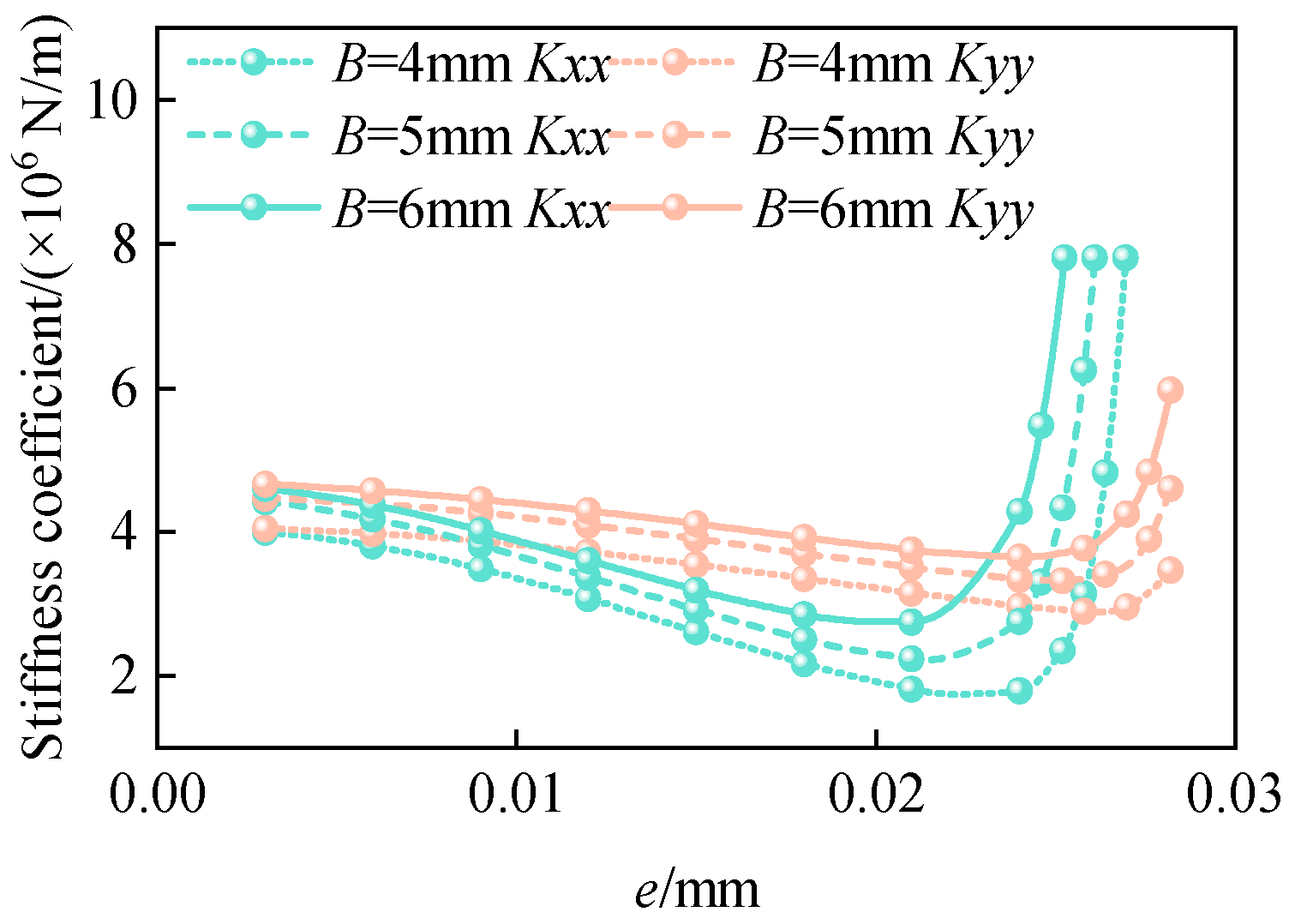
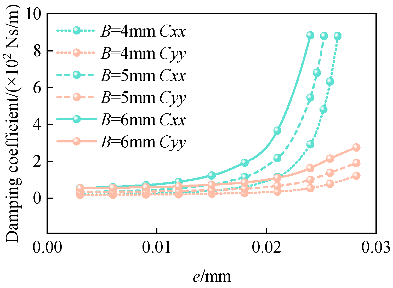
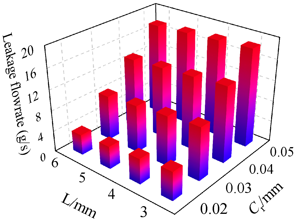
When the minimum film thickness is greater than 0.005 mm, the pressure difference effect of Poiseuille flow dominates, and as the eccentricity increases, the dynamic pressure effect of Couette flow is significantly enhanced. A sealing radial clearance of 0.03 mm and a larger floating ring width exhibit better dynamic performance of the gas film.
(3)
Enhancing the differential pressure effect of Poiseuille flow and improving the pressure distribution of Couette flow are key focuses for further improving the sealing performance of the floating ring.

Author Contributions

Methodology, S.L. (Shicong Li); Project administration, S.L. (Shuangxi Li); Writing—original draft, S.Z.; Writing—review and editing, R.M. All authors have read and agreed to the published version of the manuscript.

Funding

This research received no external funding.

Data Availability Statement

Data is contained within the article.

Conflicts of Interest

The authors declare no conflicts of interest.

Nomenclature

C = damping coefficient [Ns/m]
C r = radial clearance [mm]
D = diameter of gas film [mm]
e = eccentricity [mm]
h = film thickness [mm]
h c = critical film thickness [mm]
h min = minimum film thickness [mm]
K = stiffness coefficient [N/m]
L = Width of gas film [mm]
M = average molar mass of the gas
P = film pressure [Pa]
P 1 = inlet pressure [Pa]
P 11 = upstream pressure [Pa]
P 2 = outlet pressure [Pa]
P 22 = downstream pressure [Pa]
R = molar gas constant
R 0 = radius of gas film [mm]
t = time [s]
U = velocity [m/s]
u p = axial flow velocity [m/s]
w = relative eccentricity
Δ x , Δ y = vibration in the x, y direction
x , y = perturbation displacements
x ˙ , y ˙ = perturbation velocities
α = attitude angle
μ = air viscosity [ Pa s ]
ν = excitation frequency [Hz]
σ = combined standard deviation
σ 1 = standard deviations of carbon
σ 2 = standard deviations of casing
Ω = whirl frequency [Hz]
ξ 1 = pressure loss coefficient
ρ = density [kg/m3]
Re = Reynolds number

References

  1. Jia, J.N.; Chen, Z.; Li, J.M.; Dong, G.G.; Hao, J. Structure and development of floating ring seals. Machinery 2007, 34, 1–3. [Google Scholar]
  2. Xia, P.; Liu, Z.S. Effects of structure elasticity on leakage and rotordynamic coefficients of floating ring seals. J. Propuls. Technol. 2017, 38, 2815. [Google Scholar]
  3. Zhang, J.Y.; Wang, L.H.; Su, X. Studies on leakage characteristics of floating ring seal based on reynolds equations and fluid numerical analysis. Machinery 2017, 44, 21–26. [Google Scholar]
  4. Chen, Z.; Gao, C.Y.; Fan, W.C. Simulation of flow field in a floating-ring seal and modification of its leakage rate expression. J. Sichuan Univ. (Eng. Sci. Ed.) 2016, 48, 208–214. [Google Scholar]
  5. Hu, T.X.; Zhou, K.; Wang, X.Y.; Li, N.; Zou, H.Y. Numerical calculation and experiment on leakage characteristics of floating ring seal. J. Aerosp. Power 2020, 35, 888–896. [Google Scholar]
  6. Hu, T.X.; Wang, X.Y.; Zhou, K.; Li, Q.F.; Zou, H.Y. Effects of temperature on leakage characteristics of floating ring seal. J. Propuls. Technol. 2022, 43, 200846. [Google Scholar]
  7. Anbarsooz, M.; Amiri, M.; Erfanian, A.; Benini, E. Effects of the ring clearance on the aerodynamic performance of a CO2 centrifugal compressors annular seal: A numerical study. Tribol. Int. 2022, 170, 107501. [Google Scholar] [CrossRef]
  8. Duan, W.; Chu, F.; Kim, C.-H.; Lee, Y.B. A bulk-flow analysis of static and dynamic characteristics of floating ring seals. Tribol. Int. 2007, 40, 470–478. [Google Scholar] [CrossRef]
  9. Wang, S.P.; Ding, X.X.; Ding, J.H.; Wang, J.M. Steady-State Characteristics of Spiral Groove Floating Ring Gas-film Seal Considering Temperature-Viscosity Effect. J. Appl. Fluid Mech. 2023, 16, 891–904. [Google Scholar]
  10. Tokunaga, Y.; Inoue, H.; Hiromatsu, J.; Iguchi, T.; Kuroki, Y.; Uchiumi, M. Rotor dynamic characteristics of floating ring seals in rocket turbopumps. Int. J. Fluid Mach. Syst. 2016, 9, 194–204. [Google Scholar] [CrossRef]
  11. Song, Z.; Li, S.; Chen, X.; Liu, Z.; Zhao, T.; Huang, B. Study on the Service Performance of a Two-Stage Floating-Ring Isolation Seal for a High-Speed Turbopump with a Cryogenic Medium. Machines 2023, 11, 373. [Google Scholar] [CrossRef]
  12. Hori, Y. Hydrodynamic Lubrication; Springer: Tokyo, Japan, 2006. [Google Scholar]
  13. Fukui, S.; Kaneko, R. A database for interpolation of poiseuille flow rates for high knudsen number lubrication problems. J. Tribol. 1990, 112, 78–83. [Google Scholar] [CrossRef]
  14. Wang, X.H.; Ding, X.X.; Li, N.; Zhang, Z.M.; Si, J.X. Finite element analysis and experimental verification of fractal wear on floating ring seal end faces. CIESC J. 2023, 74, 4956. [Google Scholar]
  15. He, Z.; Guo, Y.; Si, J.; Li, N.; Jia, L.; Zou, Y.; Wang, H. Numerical Optimization Analysis of Floating Ring Seal Performance Based on Surface Texture. Lubricants 2024, 12, 241. [Google Scholar] [CrossRef]
  16. Zhao, H.; Jiang, J.Y.; Sun, D.; Wang, S.; Li, Y. Numerical study on static and dynamic characteristics of an integral floating ring seal with shallow groove dynamic pressure. J. Aerosp. Power 2024, 39, 91–101. [Google Scholar]
  17. Mariot, A.; Arghir, M.; Hélies, P.; Dehouve, J. Experimental analysis of floating ring annular seals and comparisons with theoretical predictions. J. Eng. Gas Turbines Power 2016, 138, 042503. [Google Scholar] [CrossRef]
  18. Bae, J.H.; Kwak, H.D.; Heo, S.J.; Choi, C.H.; Choi, J.S. Numerical and experimental study of nose for Lox floating ring seal in turbopump. Aerospace 2022, 9, 667. [Google Scholar] [CrossRef]
  19. Arghir, M.; Nguyen, M.H.; Tonon, D.; Dehouve, J. Analytic modeling of floating ring annular seals. J. Eng. Gas Turbines Power 2012, 134, 052507. [Google Scholar] [CrossRef]
  20. Banakh, L.Y.; Barmina, O.V. Rotor system oscillations under the rotor rotation inside floating elements. J. Mach. Manuf. Reliab. 2018, 47, 6–12. [Google Scholar] [CrossRef]
Figure 1. Sketch of floating ring seal structure.
Machines 12 00860 g001
Figure 2. Schematic diagram of wedge clearance.
Machines 12 00860 g002
Figure 3. Relative motion of the floating ring and rotor.
Machines 12 00860 g003
Figure 4. Analysis model mesh generation.
Machines 12 00860 g004
Figure 5. Floating ring seal geometry.
Machines 12 00860 g005
Figure 6. Steady-state pressure distribution.
Machines 12 00860 g006
Figure 7. Dynamic pressure Pxr distribution.
Machines 12 00860 g007
Figure 8. Stiffness comparison.
Machines 12 00860 g008
Figure 9. Damping comparison.
Machines 12 00860 g009
Figure 10. Direct stiffness.
Machines 12 00860 g010
Figure 11. Direct damping.
Machines 12 00860 g011
Figure 12. Effect of clearance on stiffness.
Machines 12 00860 g012
Figure 13. Effect of clearance on damping.
Machines 12 00860 g013
Figure 14. Stiffness at different working conditions.
Machines 12 00860 g014
Figure 15. Damping for different working conditions.
Machines 12 00860 g015
Figure 16. Perturbation frequency analysis.
Machines 12 00860 g016
Figure 17. Pressure distribution.
Machines 12 00860 g017
Figure 18. Reynolds number distribution.
Machines 12 00860 g018
Figure 19. Effect of structural parameters.
Machines 12 00860 g019
Figure 20. Effect of pressure on leakage.
Machines 12 00860 g020
Figure 21. Rotor speed analysis.
Machines 12 00860 g021
Figure 22. Temperature analysis.
Machines 12 00860 g022
Figure 23. Floating ring seal test rig.
Machines 12 00860 g023
Figure 24. Validation of test results.
Machines 12 00860 g024
Table 1. Grid independence verification.
Number of Grids47290017762836
K x x / × 10 6   N / m 1.7971.8021.8041.804
C x x / × 10 2   N / m 1.1461.1461.1461.146
Table 2. Calculated working conditions.
Upstream pressure P11/kPa 17 33 52 71 95
Downstream pressure P22/kPa713223145
Disclaimer/Publisher’s Note: The statements, opinions and data contained in all publications are solely those of the individual author(s) and contributor(s) and not of MDPI and/or the editor(s). MDPI and/or the editor(s) disclaim responsibility for any injury to people or property resulting from any ideas, methods, instructions or products referred to in the content.

