Abstract
The automotive industry is one of the most demanding sectors of all manufacturing industries due to its competitiveness. It is necessary to innovate through the implementation of automated and robotic equipment, leading to cycle time and labor cost reduction. This work aims to design semi-automatic equipment to assemble cabling connectors used in the automotive sector, replacing a manual process currently taking place in an automotive components company. In the proposed equipment, the operator places a connector in the equipment, and the components (pins and seals) are automatically inserted. A vision sensor with artificial intelligence then confirms the correct application. The equipment operation defined as Finite Element Method (FEM) was applied for structural verification; the materials and fabrication processes were detailed; the associated costs were calculated, and the equipment subsets were validated. The design was successfully accomplished, and the imposed requirements were fulfilled, with significant advantages over the current process, providing new knowledge on how semi-automatic systems can be deployed to enhance the productivity and quality of manufacturing processes. The design principles and insights gained from this work can be applied to other automation challenges, particularly where manual processes need to be replaced by more efficient semi-automatic or automatic systems. The modularity of the overall solution and the design concepts of the component inserter, component feeder, and assembly process allow for its use in different assembly scenarios beyond the automotive sector, such as electronics or aerospace, providing a contribution to increased competitiveness and survival in the global market.
1. Introduction
The automotive industry plays a leading role in the world economy. This industry presents itself in the market as one of the most demanding sectors of all manufacturing industries due to its competitiveness, being constantly pressured to meet tight deadlines and high-quality requirements [1]. Thus, it is necessary to upgrade processes through the implementation of automated and robotic equipment [2,3,4]. With automation, it is possible to obtain less waste and more quality and productivity [5], leading to shorter cycle times and smaller labour costs. Currently, the priority of companies is the development or acquisition of machines that use as few operators as possible, and there is a tendency for full automation in the future [6]. In automated equipment, the processes are managed automatically and without the need for significant human intervention, which increases efficiency [7,8]. Thus, fatigue and occupational diseases tend to be excluded as they are factors that affect productivity [9]. With automation, the setup time is also reduced, and assembly accuracy is guaranteed. Automation can be divided into three types: fixed; flexible; and programmable [10]. Fixed automation consists of using a machine that repeats the same automatic process without any flexibility [10,11]. In flexible automation, a computer controls product combinations and their reconfiguration in short adjustment times [10,12]. Programmable automation is flexible in the assembly or manufacturing process, but it is necessary to reprogram the automated action for new configurations [10,13]. In recent years, the introduction of more advanced automation-related technology led to a further reduction in labour and an increase in productivity [14]. With intelligent feeder systems, the automotive industry can group different vehicle models on the same production line. This principle can also be used on assembly lines for small automotive components. On the other hand, the demand for robots has significantly increased because they are robust, fast, flexible, and highly accurate [15]. These are more economical than human labour as they are produced in greater quantity and with higher quality. Nowadays, robotics is applied all over the world [16]. Although robots are expensive, they have a lower cost per component, high efficiency, and high production [10]. Nowadays, most manufacturing processes require robotised operations, and the automotive industry is currently the most robotised industry. More and more manufacturing processes are carried out using automated machines, and robotic solutions are progressively used to increase production and assist the operator [17,18].
In the field of engineering design, the systematic development of products and equipment follows structured methodologies aimed at optimising functionality, efficiency, and cost-effectiveness [19]. According to Pahl et al. [20], developers of the Systematic Design Approach, engineering design processes typically involve stages such as conceptual design, embodiment design, and detailed design, each providing a framework for turning abstract ideas into practical solutions. This approach is used broadly in mechanical engineering and product design, especially for complex, multi-component systems. One key area of focus in modern engineering design is the integration of automation to enhance production efficiency and reduce human error, which constitutes the Product Development Process developed by Ulrich and Eppinger [21]. This approach includes the steps of planning, concept development, system-level design, detail design, testing and refinement, and production ramp-up. The V-Model (Verification and Validation) was developed by Forsberg et al. [22] and applied to the context of systems engineering, providing a detailed view of verification and validation processes. This is a model primarily used in systems engineering, where each design phase is validated and verified in a parallel step. It is often used in highly regulated industries like aerospace and automotive engineering. Stuart Pugh’s Total Design approach [23] integrates the design process with business and market requirements. It uses methods like the Pugh Decision Matrix for concept evaluation, helping designers systematically compare multiple design solutions. It is used in product engineering, particularly in industries where both functional and market requirements must be balanced. The Theory of Inventive Problem Solving (TRIZ), developed by Altshuller [24], is a problem-solving methodology that focuses on resolving contradictions within the design by using inventive principles derived from patent analysis. It encourages innovation by highlighting ways to overcome common design challenges. It is especially useful in industries that require high innovation (e.g., electronics, automotive, and aerospace). The Axiomatic Design [25] focuses on creating systems where the design parameters (physical solutions) map clearly and independently to the functional requirements, reducing design complexity. This approach is used in manufacturing systems, software development, and product design. The Design Science Research (DSR) methodology is another structured methodology that, though it originates primarily from the fields of information systems and management science [26], has been increasingly adopted in engineering design, especially in research contexts [27]. This methodology focuses on creating and evaluating artefacts (like models, systems, or processes) to solve identified problems. It combines scientific rigour (research-based problem solving) with practical relevance (ensuring solutions have real-world applicability). Another influential approach is the Design Research Methodology (DRM) proposed by Blessing and Chakrabarti [28]. DRM offers a comprehensive framework specifically tailored for design research aimed at understanding and improving design processes and outcomes. Unlike other methodologies, DRM places a strong emphasis on the research dimension of design projects, particularly the systematic investigation of design processes to generate knowledge that can improve both design practice and theory. By systematically guiding the research through descriptive and prescriptive phases, DRM ensures that the outcomes of the design are both scientifically validated and practically applicable. In addition to these established methodologies, several more recent developments have gained prominence in the field of engineering design. These approaches address modern challenges in product development, such as reducing complexity, improving reliability, and enabling automation, including the following:
- Design for Manufacturing and Assembly (DfMA) is a concept that integrates design and manufacturing considerations early in the design process to simplify production and reduce costs. The main goal of DfMA is to design products that are easier and more cost-effective to manufacture and assemble, minimising parts and simplifying assembly operations [29]. This approach ensures that the design is optimised not only for functionality but also for the efficient production;
- Graph-based design languages are an approach to formalising design processes using mathematical graph structures to represent the relationships between components, systems, and functions. This method provides a visual and algorithmic means to explore design alternatives and optimise complex systems, enabling designers to handle intricate dependencies and constraints more effectively [30];
- Fault-tolerant design is a critical approach used to ensure that systems continue to operate reliably even when some of their components fail. In the context of automated systems, this approach is essential for maintaining high levels of uptime and minimising the risk of costly production delays. Fault-tolerant design involves identifying potential failure points and incorporating redundancy, error detection, and recovery mechanisms into the system [31].
Automated and robotised systems have become increasingly complex, and both implementations and use of protocols are described in the scientific literature [32,33,34,35], eventually applying a specific engineering design approach. Costa et al. [36] solved quality problems in the transmission system of automotive windshield wipers using a design approach resembling the DSR methodology in the applied steps. The previous system was semi-automatic and could not detect and reject components during the process prior to assembly, leading to the production of defective parts. For optimisation, the equipment and the product to be manufactured were analysed. Subsequently, the best solutions for the detected faults were discussed and chosen. A fully automated system capable of detecting faulty components was then implemented. The equipment now has a 100% quality control, i.e., it no longer manufactures defective products. Furthermore, production rates remained within automotive industry standards, and productivity increased by 19%. Figueiredo et al. [37] added an automatic coating stripping operation onto an existing machine to produce control cables for the automotive industry, using three simple steps as a design approach: a study of the manual stripping system, a study of the machine cycle, and a redesign of the mechanisms to comply with the specification. The new stripping operation removes the coating from the cable edges, allowing the injection of zamak terminals without die-casting defects. The equipment’s production cycle was analysed, and an automated solution based on multiple blades did not affect productivity. The proposed device produces cables up to 2.5 m long, stripped on both sides, with a cycle time of 7 s. Santos et al. [38] presented a new solution to transport conduits used to protect control cables for the automotive industry along an automatic production line in which other operations were applied to the control cables, such as cutting, deburring, and punching of terminals at the ends. This work was divided into three steps: establishing the main requirements for the new concept; finding a solution for every identified problem; and combining all the solutions found into one system that surpassed the identified problems. As a result, a simple and economical solution to be implemented in the line was studied and developed, which had a much higher reliability than the current mechanism. After implementation, the setup time was reduced by 97%, and system stoppages due to problems dramatically decreased. In the scope of robotics, Pereira et al. [39] designed an automatic robotic cell to insert clips into two different car parts after their fabrication by an injection process. A self-developed design approach was described, including elements of both DSR and V-Model approaches, as follows: analysis of requirements; information gathering; equipment division in sub-assemblies; definition of principles for each sub-assembly; preliminary design with possible solution and solution selection using a Strengths, Weaknesses, Opportunities, and Threats (SWOT) analysis; design using Computer-Aided Design (CAD) and the FEM; and validation by prototype construction and workflow simulation. Resulting from this work, a six-axis robot with a special tool to hold the clips was implemented. An automatic clip-loading system was designed, which loaded the clips in the tool and delivered them to the robot while the empty tool was left by the robot to charge with clips. The equipment was fabricated, validated in a real scenario, including meeting the cycle time imposed by the client, and delivered for factory implementation. Michalos et al. [40] addressed the implementation of a robotic system for a collaborative human–robot assembly process. An active workflow design methodology was proposed by the authors, starting with assembly task identification, followed by operation sequence definition, resource alignment, layout design, collaborative workflow generation, safety concept definition, engineering system development, and finally, risk assessment. The steps were not tight since feedback in each stage could lead to modifications in a previous one and recalculation. The proposed solution aimed to combine heavy-duty industrial robots with human intervention in a fenceless workspace. Augmented reality glasses and smartwatches enabled the closing of the robot–human communication loop. The system was validated by applying the concept to a case study in the automotive industry. A safety analysis was supported by Safety Related Parts/Control Systems (SRC/CS) design approach, further corroborating the possibilities of human–robot collaborations.
This work aims to design semi-automatic equipment to assemble cabling connectors used in the automotive sector, replacing a currently manual process currently taking place in an automotive components company. In the proposed equipment, the operator places a connector in the equipment, and the components (pins and seals) are automatically inserted. A vision sensor with artificial intelligence then confirms the correct application. The equipment operation was defined; FEM was applied for structural verification; the materials and fabrication processes were detailed; the associated costs were calculated, and the equipment subsets were validated.
2. Methods
2.1. Design Approach
The DSR design methodology focuses on the creation and evaluation of artefacts, such as models, processes, and systems, to address real-world problems while simultaneously contributing to academic knowledge [27]. The DSR approach follows a structured process in which researchers and practitioners collaborate to define the problem, design the artefact, and evaluate its effectiveness. This dual emphasis on problem-solving and knowledge generation makes DSR especially relevant for projects involving innovation and the development of new technologies, such as the semi-automatic assembly equipment presented in this work. The key stages of the DSR process applied to the design and development of the equipment are as follows:
- Problem description—Examination of the existing system or process, identifying inefficiencies, limitations, or areas where improvements can be made. This stage involves describing specific problems that the new design will address;
- Goals and requirements—Establishment of clear goals and requirements for the new solution. This includes both functional objectives, such as operational efficiency or reliability, and any constraints related to cost, materials, or technology;
- Design and development—Creation of a new design or concept that meets the defined objectives. This stage involves iterative design processes, where multiple concepts may be generated and refined;
- Demonstration—Materialisation of the developed concept by constructing a prototype or implementing a functional CAD model. This concept should be capable of demonstrating the core functions of the equipment;
- Evaluation—Assessing the performance of the developed solution through virtual or physical testing. This stage involves verifying whether the equipment complies with the established goals and requirements;
- Conclusions—Consist of the final assessment comparing the results of the equipment with the goals and requirements and drawing conclusions about the overall success of the new design.
2.2. Problem Description
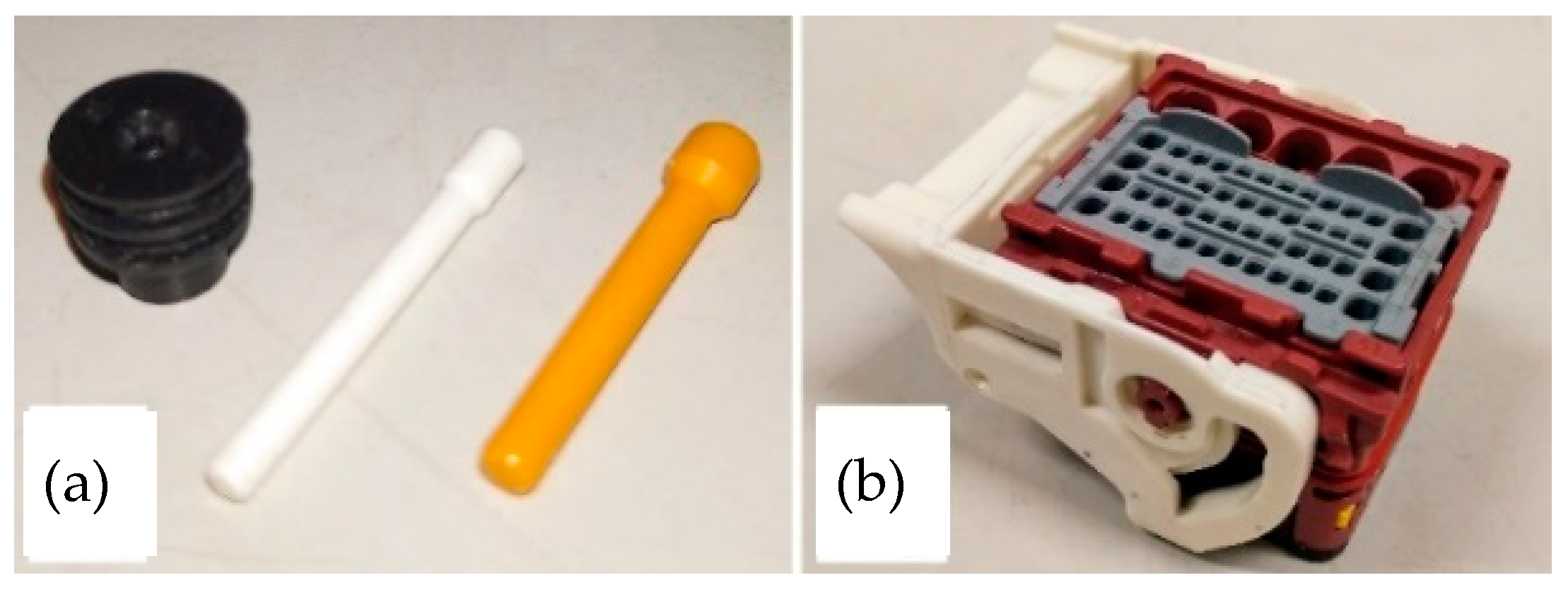
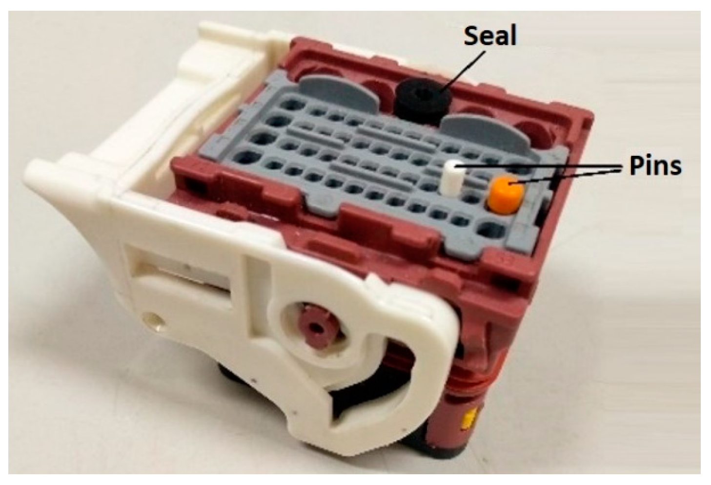
The current project arises from a challenge posed by the automotive industry. A specific company needs equipment that can perform the assembly process of automotive cabling connectors in a semi-automatic way, which are currently assembled manually and pose a significant cost and human resource allocation to the company, serving as the process bottleneck for a subsystem being delivered for a vehicle manufacturer. Thus, specific equipment is necessary to overcome these limitations and increase the company’s competitiveness. The mentioned connectors are part of the wiring harnesses that interconnect all the electrical parts of the vehicle. Some connector channels are selected to be connected to the ends of electrical cables, which may or may not belong to the same harness, and the ones chosen are not always the same because they depend on the function to be performed in a certain part of the vehicle. The connector assembly equipment should work semi-automatically to insert components (pins and seals) into various connectors. The function of the components is to seal/close the free channels of the connector, i.e., the channels that are not connected to the ends of electrical cables. Figure 1a shows the pins and the seal that the equipment inserts. Figure 1b shows the connector being worked on. Figure 2 shows the pins and seal inserted into the connector to assemble.
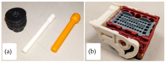
Figure 1.
Seals and pins (a) and connector to assemble (b).
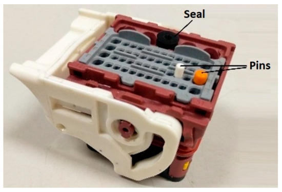
Figure 2.
Pins and seal inserted into the connector to assemble.
2.3. Goals and Requirements
The main goal of this work involves designing equipment capable of performing the semi-automatic assembly of cabling connectors used in vehicles. The assembly equipment to be designed is a semi-automatic system intended for the insertion of components (pins and seals) into various types of connectors. The function of these components is to seal or close the unused channels of the connector, meaning the channels that are not connected to the ends of electrical cables.
The requirements are divided into project requirements, pin and seal assembly in the plastic connector, and pin and seal detection in the plastic connector. The project requirements, pre-defined by the client company, aim to ensure the good functionality of the equipment (Table 1). For the pin and seal assembly in the plastic connector, several assembly considerations were considered (Table 2). Pin and seal detection in the plastic connector is carried out to ensure correct insertion, which can be achieved by various methods and equipment (Table 3 shows the main considerations to be taken into account when selecting the type of detection to be implemented).

Table 1.
Project requirements.

Table 2.
Pin and seal assembly requirements.

Table 3.
Pin and seal detection requirements.
3. Results
3.1. Final Equipment and Operation Sequence
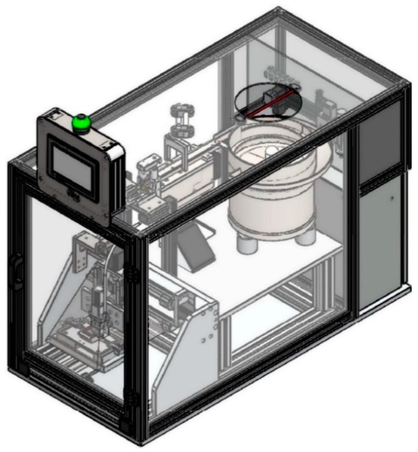
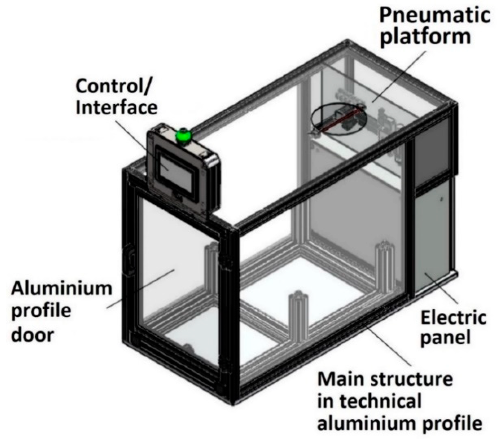
The proposed equipment is a prototype designed for series production (Figure 3). The design has been developed to facilitate future modification of the workboard, which is necessary to assemble different connectors. The equipment allows for the simple replacement of the feeder system and the inserter for the assembly of different components. Additionally, the equipment is assembled using mechanically fastened connections. This equipment is semi-closed regarding the exterior, having only one door and an opening on its top part. The door allows the operator to place the workpiece on the workboard, while the opening enables the deposition of components in the feeder. With this isolation, the safety of the operators is ensured.
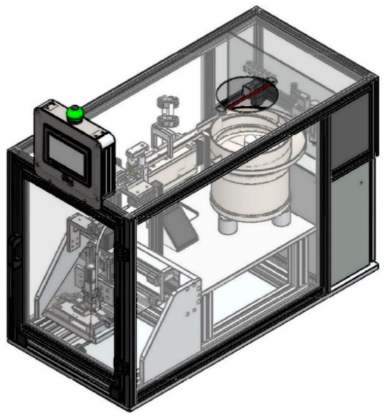
Figure 3.
Isometric view of the equipment.
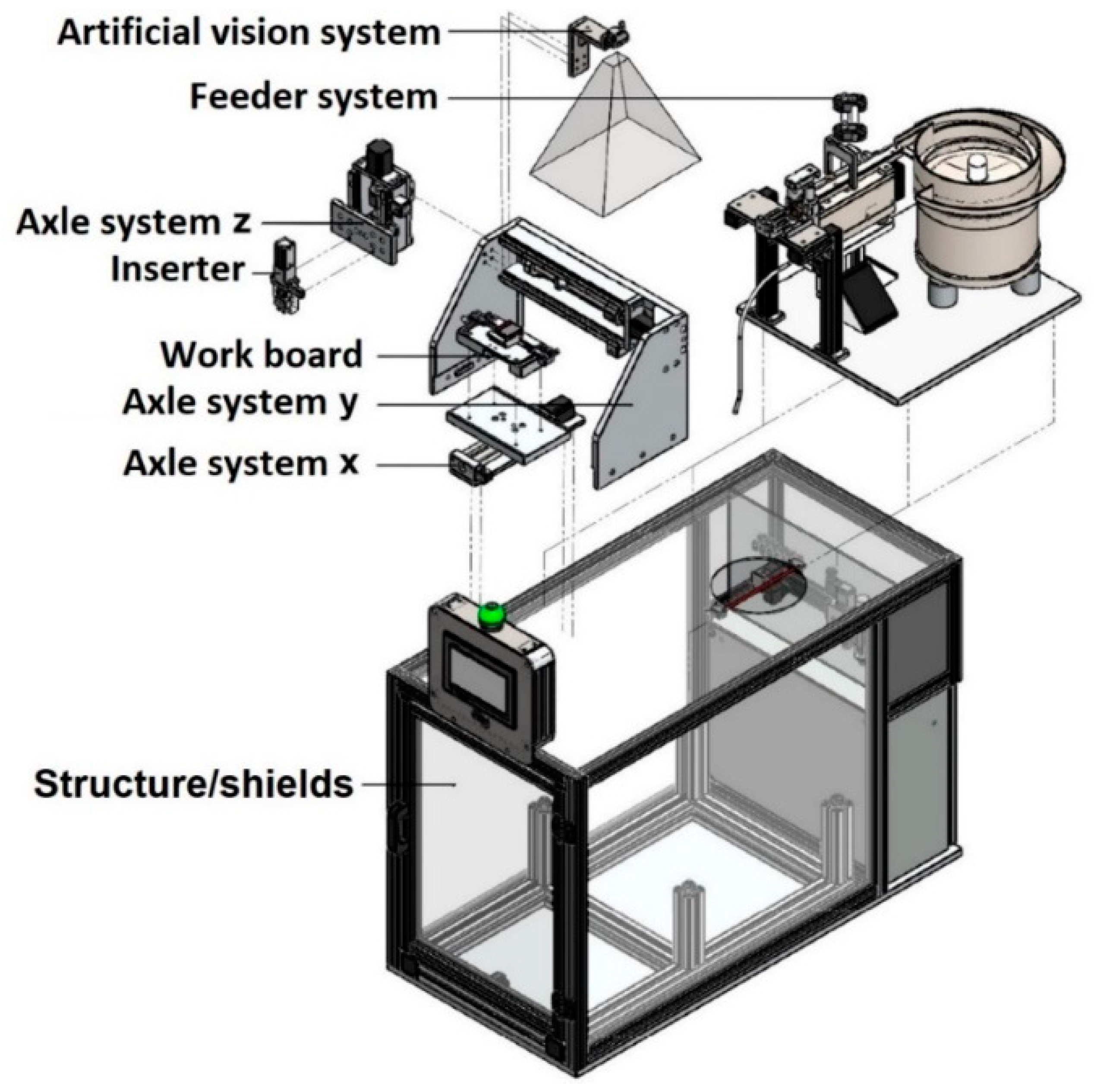
The operation of the final equipment is described as follows. First, the operator deposits the components in bulk through an opening in the equipment. Then, the type of connector to work on is selected using the console. The operator puts the connector into the nest of the workboard and closes the door of the equipment. Next, the inserter automatically inserts the components, which include pins and seals, into the connector according to the pre-set programming. Afterwards, the artificial vision system checks to ensure that the components are correctly inserted into the connector. Then, the equipment informs the operator whether the insertion of the components is correct and releases the connector. Finally, the operator opens the door and removes the connector from the equipment. The equipment is composed of subsets that work together to ensure optimal performance. The arrangement of these subsets was carefully evaluated for space, minimising the overall dimensions. These subsets consist of the following (Figure 4):
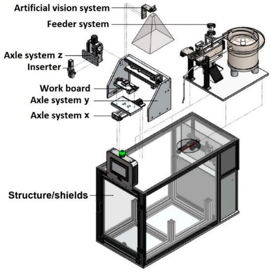
Figure 4.
Layout of the equipment.
- Structure/shields: block access to the mechanisms to ensure the operator’s safety during operation;
- Workboard: has a nest where the operator positions the connector, which blocks it in the x and y-axes, while the workboard blocks it in the z-axis. It detects the presence of the connector;
- Inserter: inserts the pins/seals into the connector. This system receives the pins and seals from the feeder system and inserts them into the workpiece by application of a vertical force;
- Axle systems: responsible for positioning the inserter at the insertion points of the components. The guided movements of the axles are driven by electric motors;
- Feeder system: to provide the correct orientation and separate the components (deposited in bulk);
- Artificial vision system: checks correct assembly by analysing the entire insertion area (upper face) of the connector and verifying if the pins and seals are in the pre-defined locations.
3.2. Subset Detail
The various subsets that make up the equipment are described next. These are the structure/shields, workboard, inserter, axle systems, feeder system, and artificial vision system.
3.2.1. Structure/Shields
The structure/shields of the equipment are shown in Figure 5, providing operator safety during operation. The equipment dimensions are 1080 × 700 × 530 mm3. Isolated mechanisms with polycarbonate and Dibond® materials provide safety, with the polycarbonate enabling visibility inside the equipment. The magnetic lock and plate (Figure 6a) mechanically secure the door through magnetic forces.
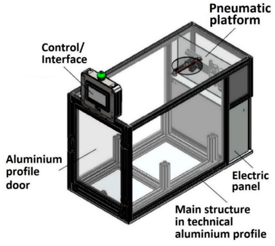
Figure 5.
Layout of the structure/shields.

Figure 6.
Magnetic lock and plate (a), magnetic safety switch (b), and support feet (c).
A magnetic safety switch depicted in Figure 6b verifies whether the door is properly closed and transmits this information to the automation system. If the door is not properly closed, the equipment will not operate. The equipment is supported by four feet, such as those shown in Figure 6c, to maintain stability and levelness on the workbench. A pneumatic platform provides pressurised air to power the equipment. The electric panel incorporates the necessary electrical components, and its dimensions were selected based on the size of the equipment and the expected number of electrical elements. The programmable interface device provides information to the operator on the status of the equipment and the steps to be executed, with a warning light of different colours to indicate the equipment’s status. The structure supports all loads exerted by the subset and is made of technical aluminium profiles, allowing for connection flexibility for a wide variety of connectors and components. The aluminium profile door gives the operator access to the inside.
3.2.2. Workboard
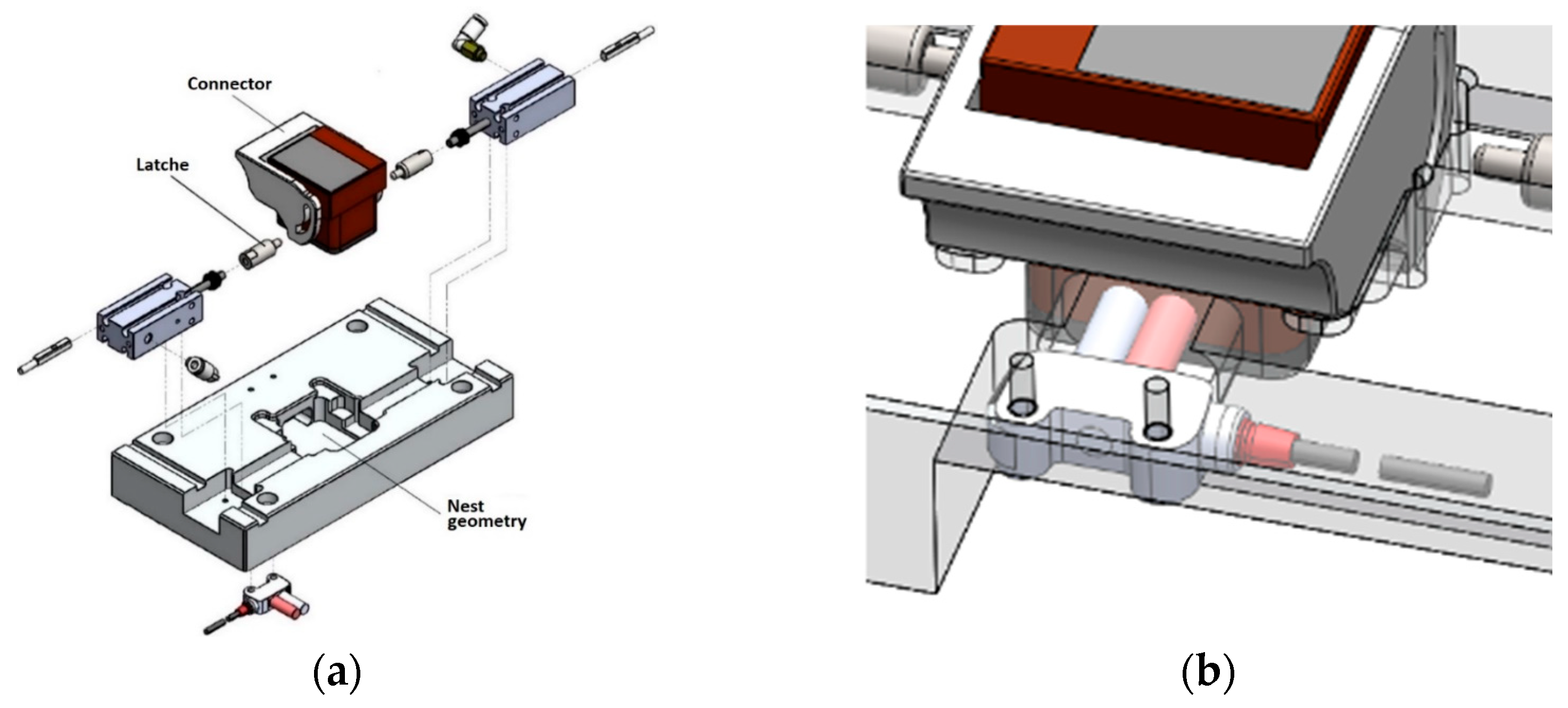
The operator places the connector to assemble in a nest on the workboard (Figure 7a), which secures the connector in the x and y-axes. The upper part of the connector is left free for component insertion (pins and seals). The latches lock the connector in position on the z-axis until the insertion of components is complete. After insertion, the connector is unlocked, and the operator removes it from the nest. The short-range photoelectric sensor shown in Figure 7b verifies the presence of the connector on the workboard.
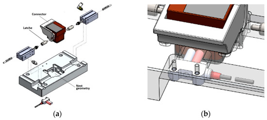
Figure 7.
Workboard layout (a) and connector detection via short-range photoelectric sensor (b).
3.2.3. Inserter
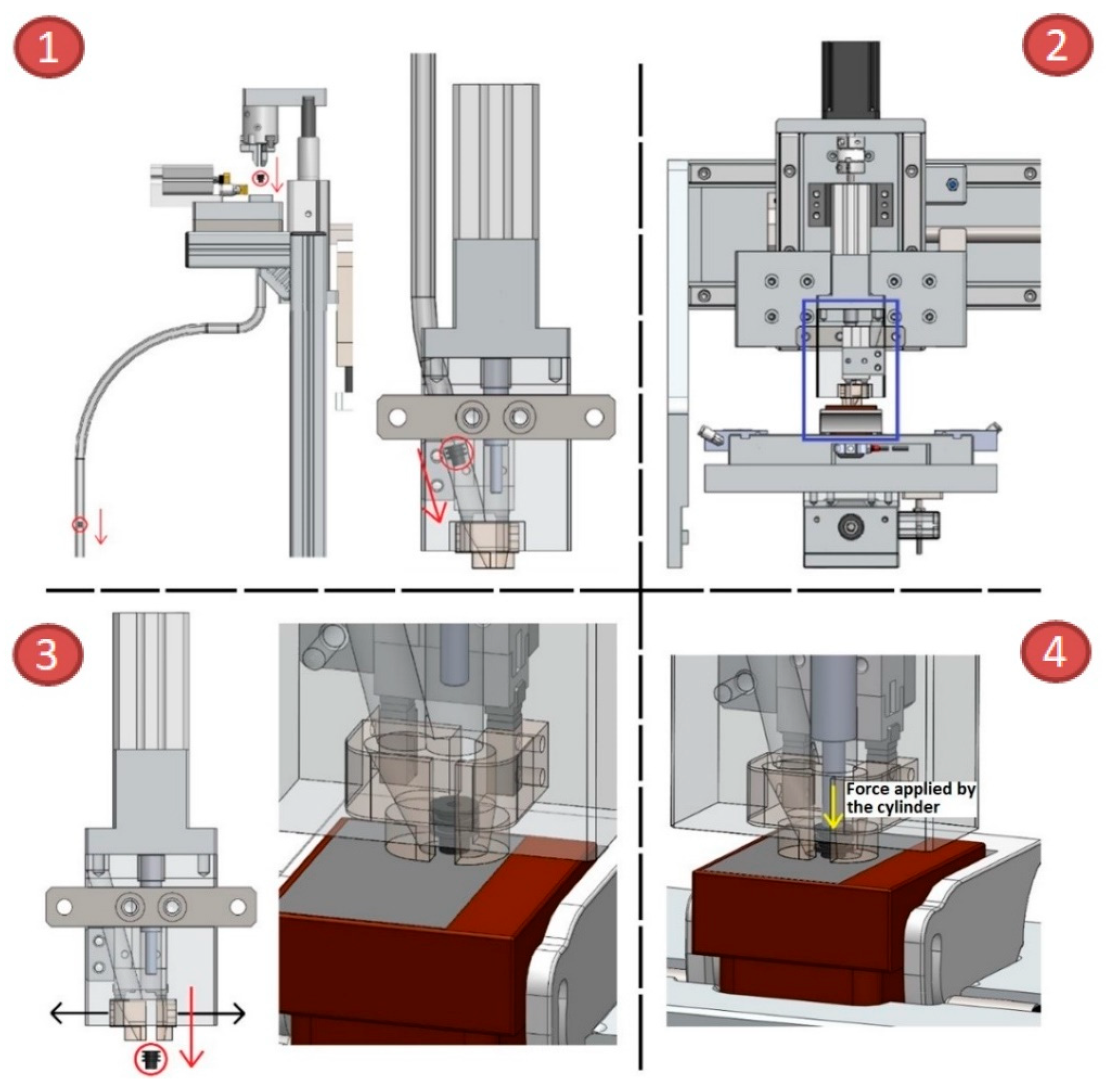
The inserter operates through the four steps represented in Figure 8:
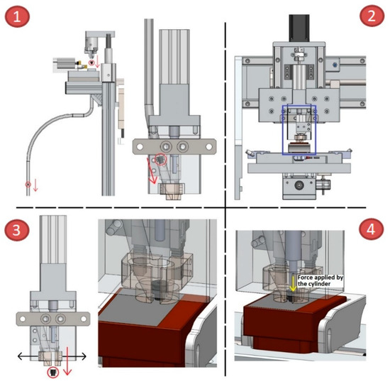
Figure 8.
Stages of operation of the inserter.
- The component is received by the inserter from the blow system, located in the feeder system;
- The equipment places the inserter on the insertion point;
- The grip opens, and the component descends to the insertion area (upper face) of the connector;
- As soon as the component descends, the insertion cylinder advances, exerting a vertical force on the component and inserting it into the connector.
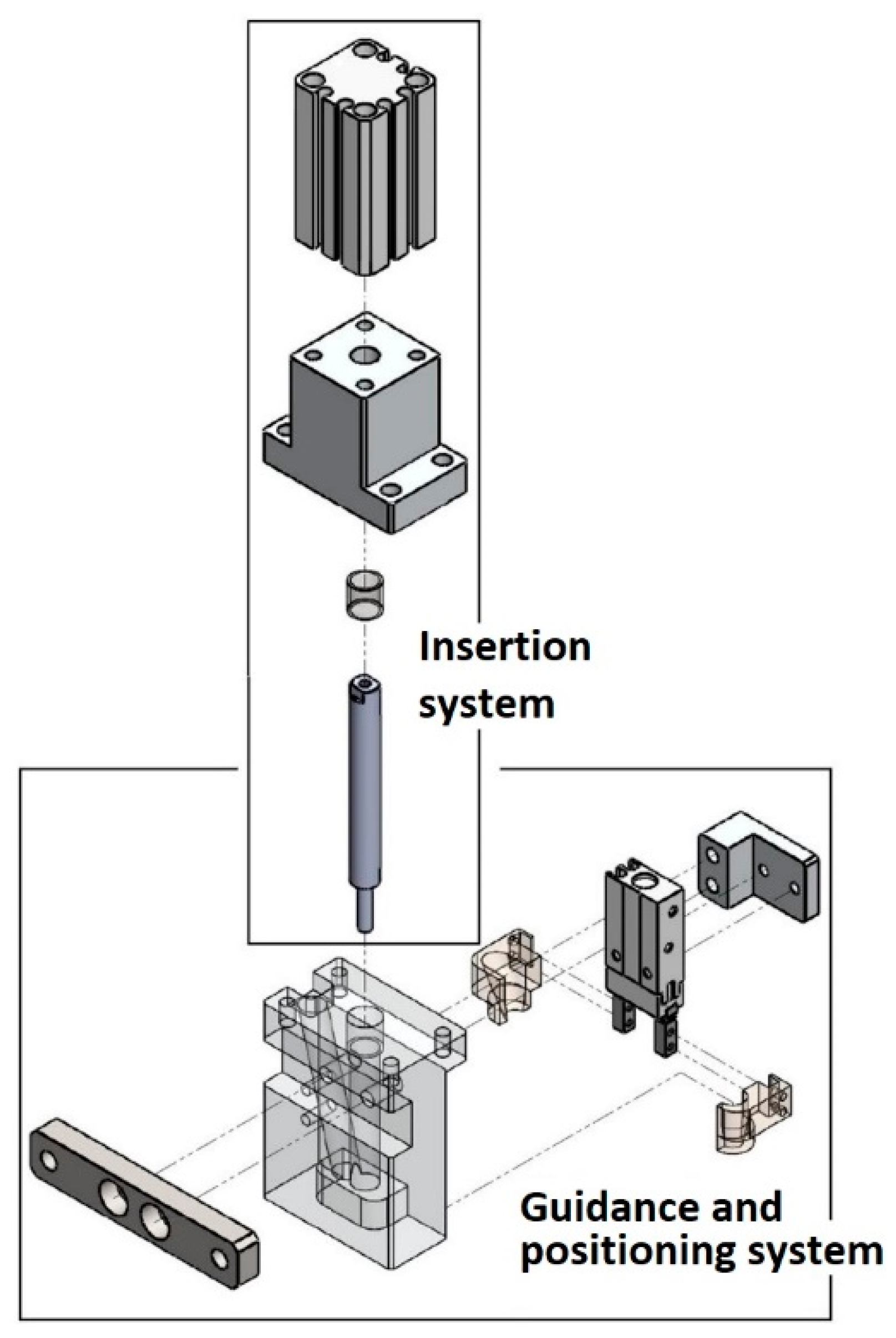
The inserter, depicted in detail in Figure 9, is responsible for receiving components, such as pins or seals, from the feeder system and inserting them into the connector. The insertion process involves applying a vertical force on the component to fit it into the connector.
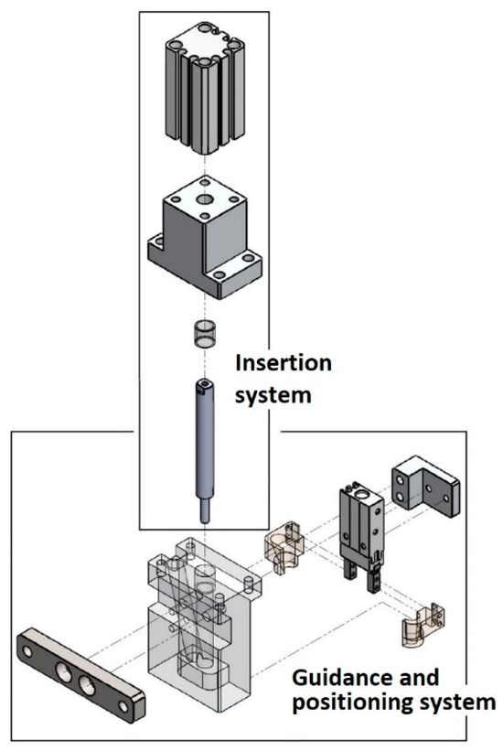
Figure 9.
Layout of the inserter.
3.2.4. Axle Systems
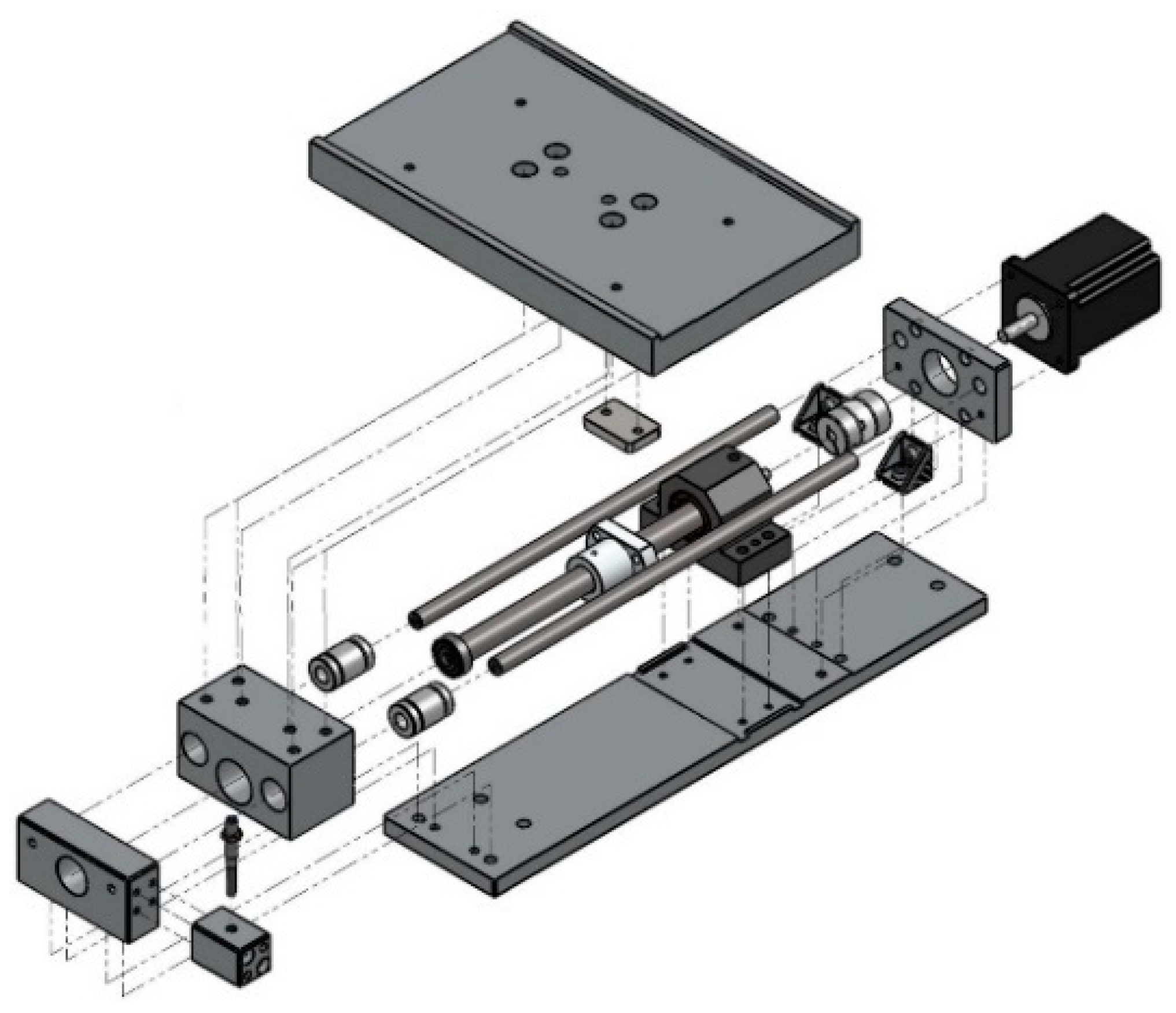
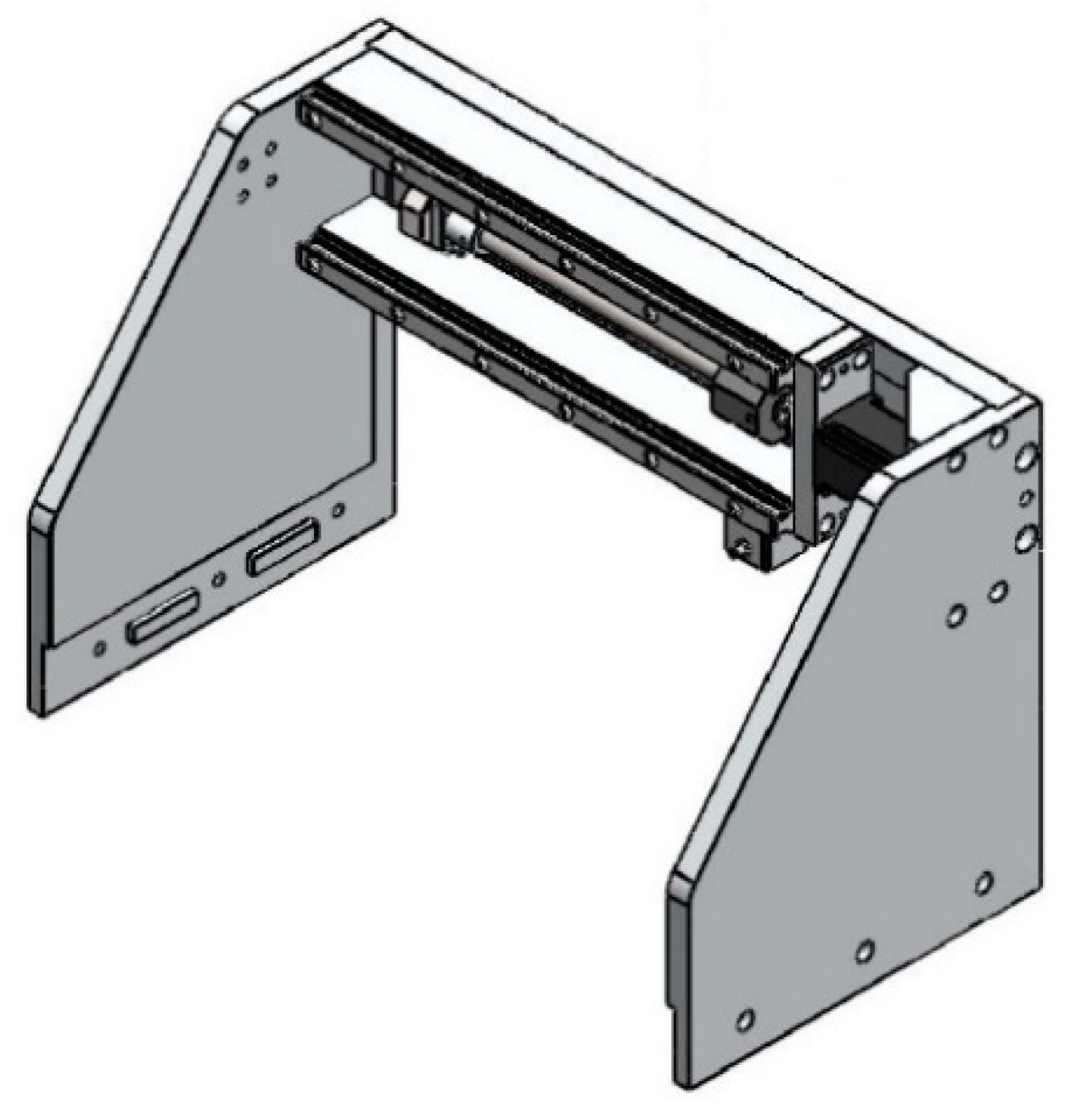
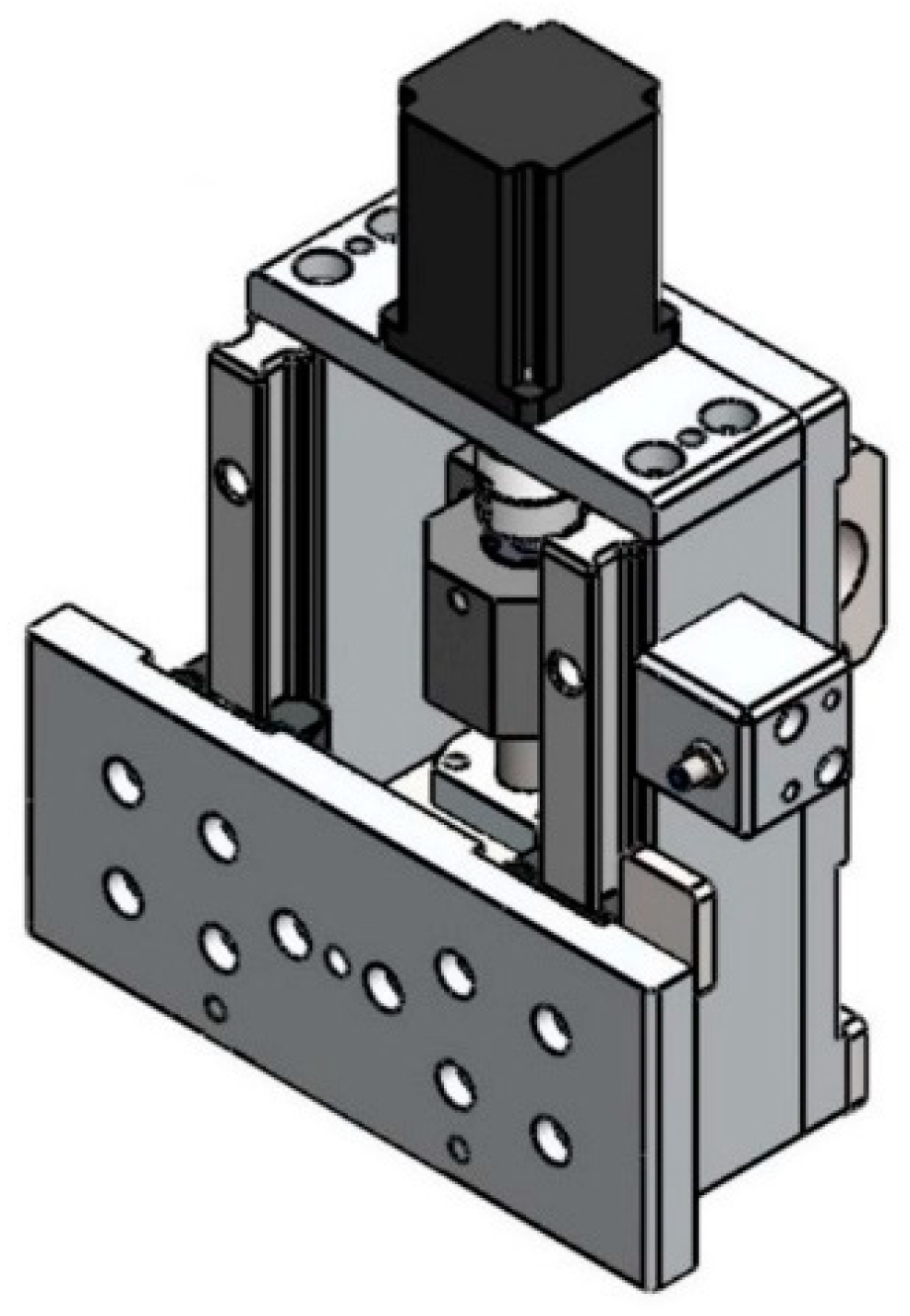
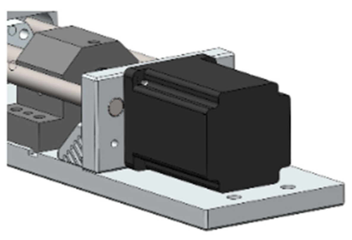
The position of the inserter at the component insertion points is determined by the axis systems presented in Figure 10, Figure 11 and Figure 12, which are equipped with electrical drives and guided movements. The linear movement in each axis is carried out by electric motors such as the one depicted in Figure 13.
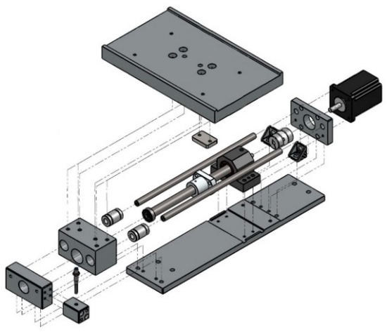
Figure 10.
Layout of the x-axis system.
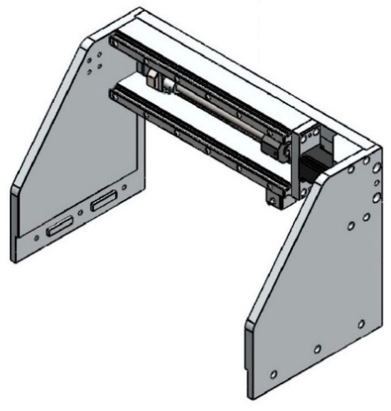
Figure 11.
Layout of the y-axis system.
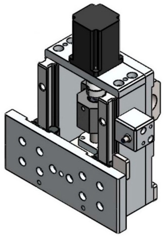
Figure 12.
Layout of the z-axis system.
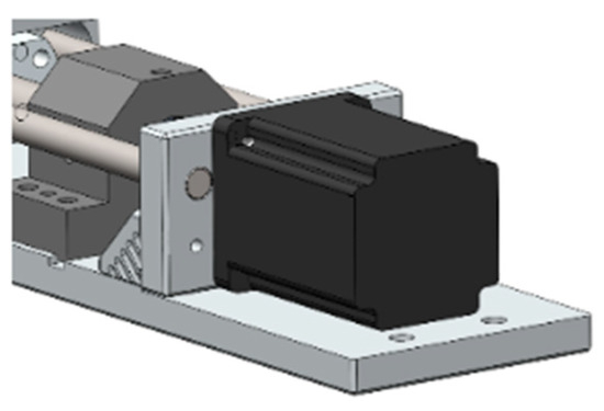
Figure 13.
Electric motor.
The x-axis system, as shown in Figure 14a, is guided by precision shafts and linear bearings, while the y-axis and z-axis systems, as shown in Figure 14b, are guided by linear guides in the form of skids and rails. The position of the “home” sensor beam, as shown in Figure 14c, represents the initial travel limit for each axis system.

Figure 14.
Precision shaft and linear bearing (a), linear guide (skid and rail) (b), and “home” sensor beam position (c).
3.2.5. Feeder System
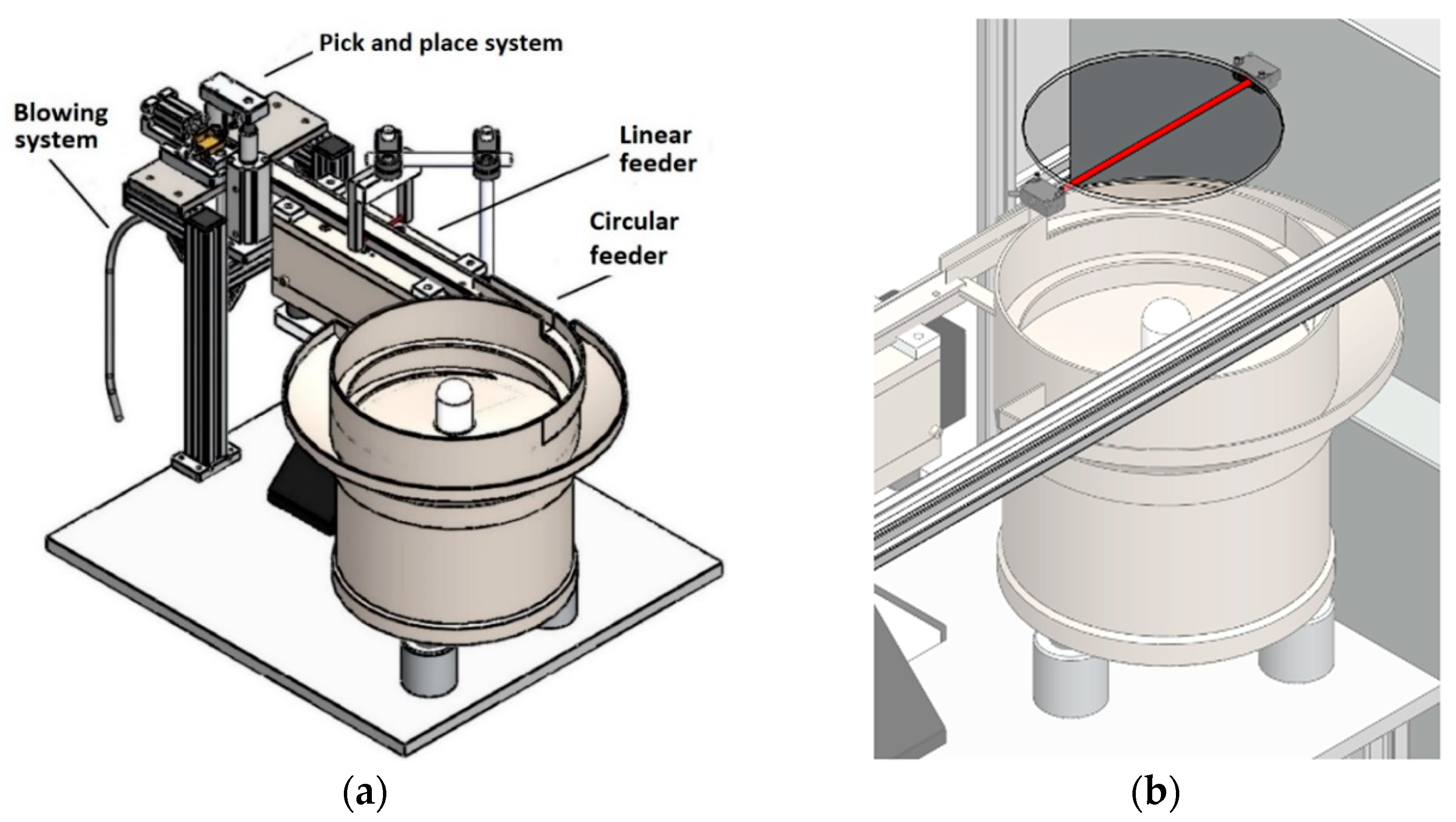
The feeder system depicted in Figure 15a operates in multiple stages. The operator first deposits the components (pins or seals) randomly and in bulk through the supply hole. Then, the circular feeder guides and positions the components correctly before they move to the linear feeder, which vibrates them to the loading point of the pick and place system, ensuring the required output rate. The pick and place system then transports the components from the linear feeder to the blowing system, which finally delivers them to the inserter. In Figure 15b, a polycarbonate plate is installed above the feeder system to prevent any foreign materials from falling into the feeders. Moreover, a supply hole and a safety sensor are in place for additional safety measures.
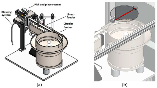
Figure 15.
Layout of the feeder system for the components (a) and polycarbonate plate, supply hole, and security sensor (b).
3.2.6. Artificial Vision System
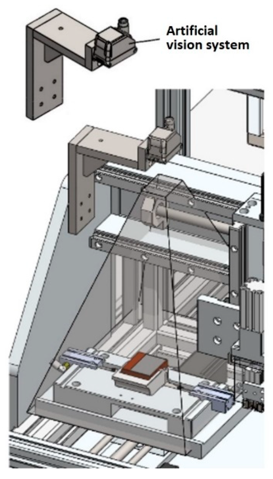
The artificial vision system represented in Figure 16 verifies the insertion of components (pins and seals) in the connector after assembly according to pre-defined programming. The inspection involves a thorough examination of the connector surface, with correct assembly determined by the components’ placement in pre-defined locations. The system signals conformity (OK) if the assembly is correct and non-conformity (NOK) if it is not.
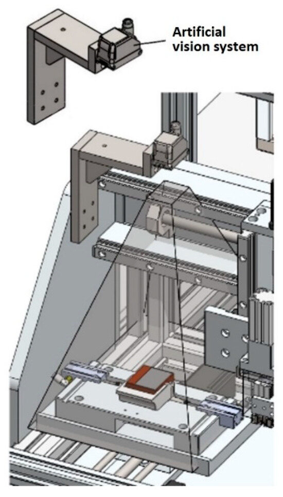
Figure 16.
Artificial vision system.
3.3. Structural Verification
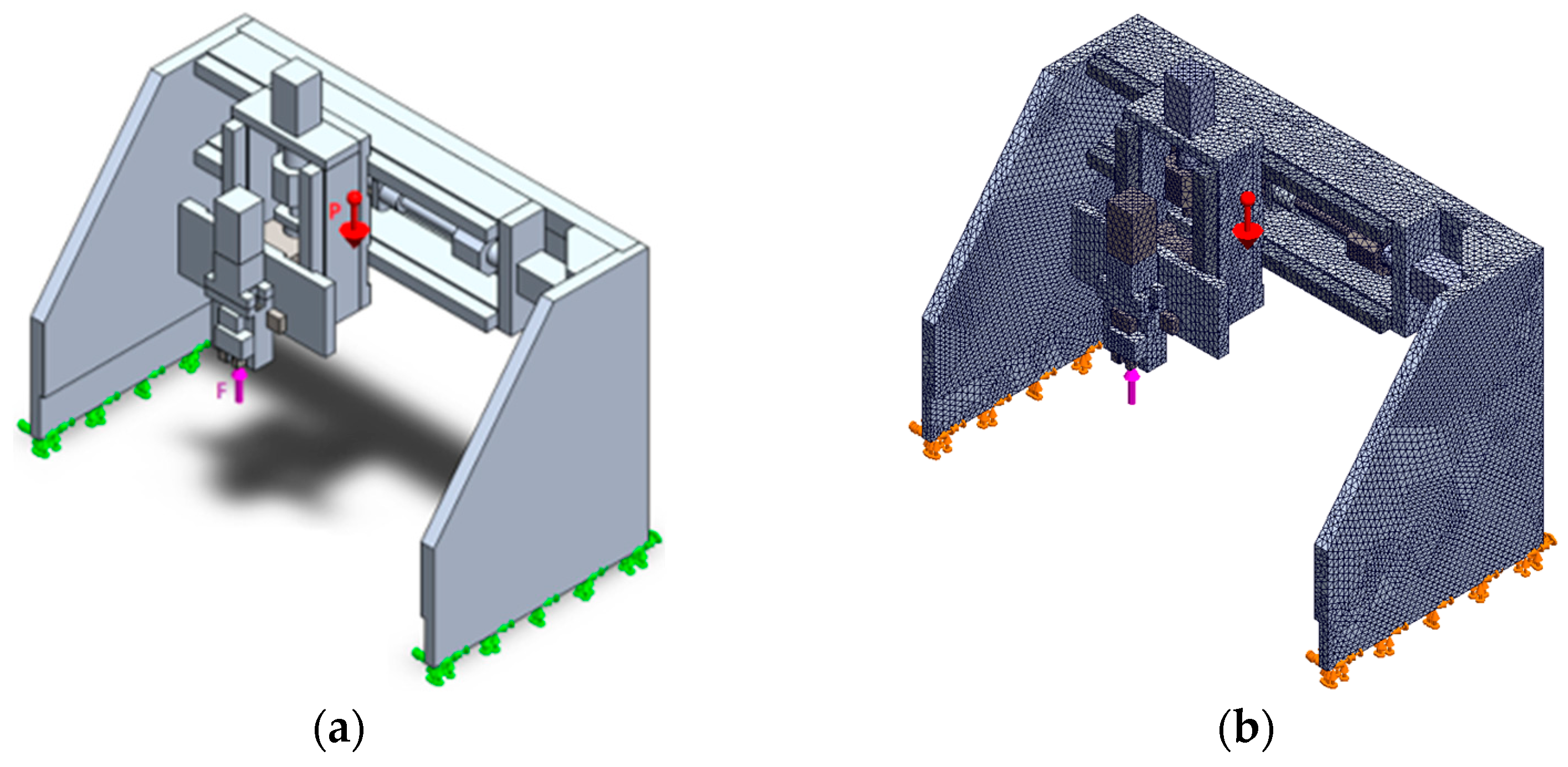
To validate the structure of the y-axis system, which corresponds to the main axle structure and also involving the z-axis system and requires stiffness and strength verification, a linear static analysis was conducted using the Simulation (FEM) module of SolidworksTM. The analysis considered the influence of the different materials used in the parts. As shown in Figure 17a, the analysis considers the impact of the load exerted by the insertion cylinder and the weight of the z-axis system with the inserter applied on the y-axis system. As boundary conditions, the bases of both side plates were clamped, which is a reasonable approximation to the real behaviour due to the mechanical fastening of this set with the structure. The reaction on the cylinder was defined as 2000 N (defined by the chosen cylinder) and applied upwards.
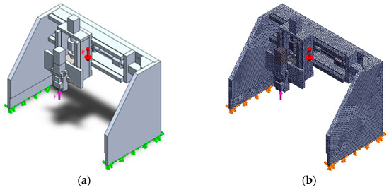
Figure 17.
Boundary conditions and loads (a) and selected mesh (b).
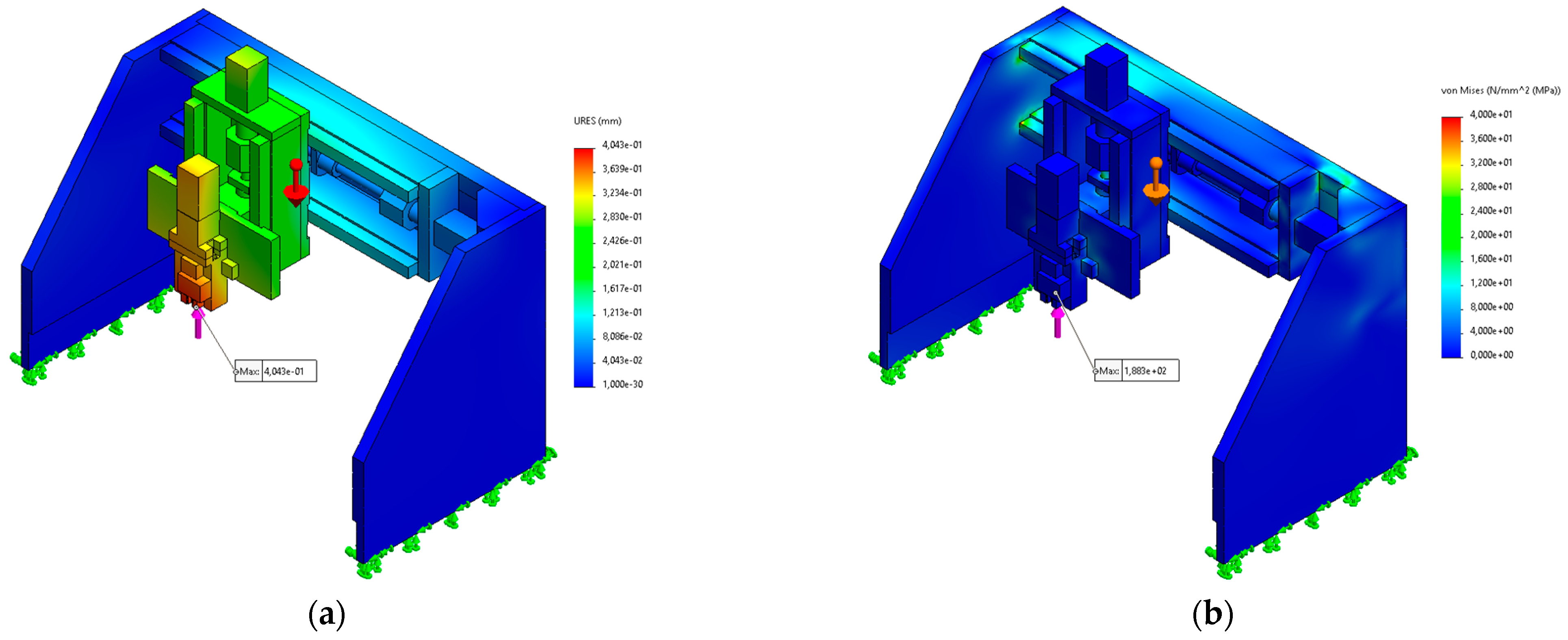
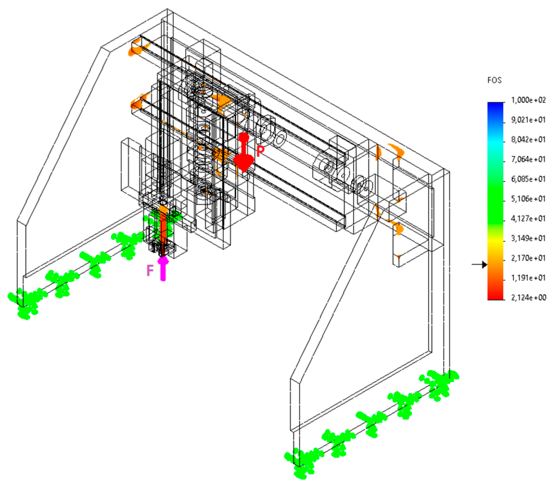
A mesh convergence study was carried out to ensure the existence of accurately predicted stresses and strains. For the analyses performed, quadratic tetrahedral elements of 10 nodes were used, and a mesh based on curvature was considered. The convergence study was executed with gradually increasing mesh sizes at three points in the model. The final mesh selected for the analysis is shown in Figure 17b, including a total of 211,733 elements. Figure 18a presents the resultant displacements (URES) in the model, emphasising that the point where the cylinder exerts force shows the maximum URES (0.404 mm). This value is considered small enough not to affect the proper functioning of the equipment or the insertion process of the component due to the existence of self-centring faces between components to be inserted and the respective housings and not affect the required insertion length. Thus, in terms of displacements, the system is considered validated. Figure 18b presents von Mises equivalent stresses with the scale limited to 40 MPa, which accounts for most regions in the model. Nonetheless, localised stress concentrations were detected near the component insertion tip, where the cylinder exerts force up to 188.3 MPa. This analysis is complemented by an iso-clipping visualisation of the factor of safety (FOS), shown in Figure 19, by filtering the data for a coefficient lower than 20 while the scale ranges from 0 to 100. The highlighted areas represent the regions of the highest stress concentration, which are typically located at the corners between the components and the component application tip. In view of the attained stress results, the y-axis design is considered validated.
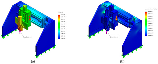
Figure 18.
URES results (a) and von Mises stresses (b) in the y-axis system.
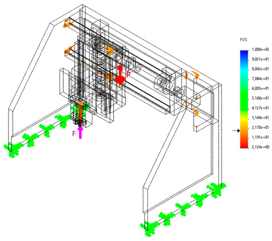
Figure 19.
FOS analysis (critical areas) for the y-axis system.
3.4. Materials and Processes
The most suitable material was selected for each component to be manufactured based on its function in the equipment and the applied loads. In summary, the selected materials for the equipment were as follows:
- Aluminium alloy 3.3547 (DIN EN-AW 5083) is the most used in the equipment due to easy machining (leading to short fabrication times), reduced weight, and acceptable strength;
- Steel 1.1191 (DIN Ck45) was chosen for parts with higher wear and loads due to its strength and hardness requirements. Some treatments are applied, including quenching, which increases resistance to wear and fatigue, nitriding, which hardens the component surface, and oxidation, which creates a protective layer to increase corrosion resistance and durability;
- Stainless steel 1.4301 (DIN X 5 CrNi 18-10) was chosen for the equipment sheets since untreated steel parts are susceptible to corrosion. Therefore, stainless steel was chosen for some parts as it does not require treatment to resist corrosion;
- Dibond (aluminium-polyethylene composite) and polycarbonate: Dibond is an opaque material purchased in sheets, with a white finish on one side and silver on the other. Polycarbonate is bought in sheets with its final dimensions, chosen to enclose the sides and top of the equipment.
The main manufacturing processes used in the production of the equipment’s parts were as follows:
- Milling: process in which material removal is accomplished by feeding the part against a rotating cutter, with relative movement in at least three axes, giving the part the desired shape and finish;
- Turning: in this machining process, a lathe is used to rotate the part while a cutting tool moves in length and depth to remove metal along the diameter, creating a revolution-based shape;
- Laser cutting: thermal process in which a focused laser beam is used to melt material, used to cut sheets and tubes with high quality and precision;
- Bending: it plastically deforms the sheet and enables the production of cylindrical, conical, and prismatic surfaces. This process is utilised for small-batch production;
- Electro-erosion: machining process that involves the destruction of metal particles through wire-induced electric discharges. This method is ideal for cutting intricate contours or complex cavities.
3.5. Working Principle
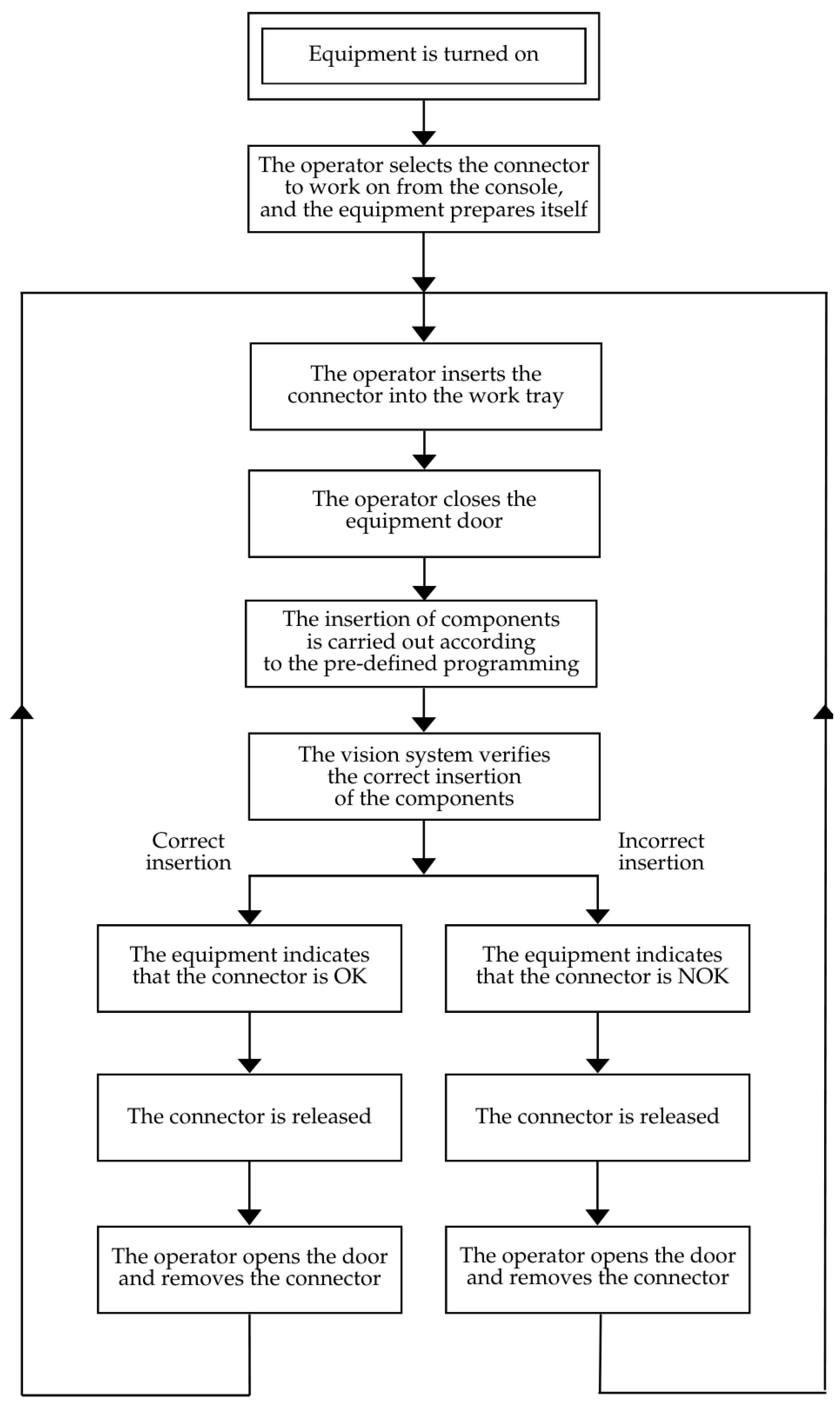
From the time the connector arrives at the equipment until it leaves, the equipment performs a series of functions responsible for assembling the components and obtaining the final product. The equipment’s operating sequence is defined in the diagram of Figure 20. As this is semi-automatic equipment, a few steps in the operation sequence require the operator’s intervention, namely, connector type selection via the equipment’s console, which indicates the references that can be assembled, followed by manual connector insertion into the workboard and door lock.
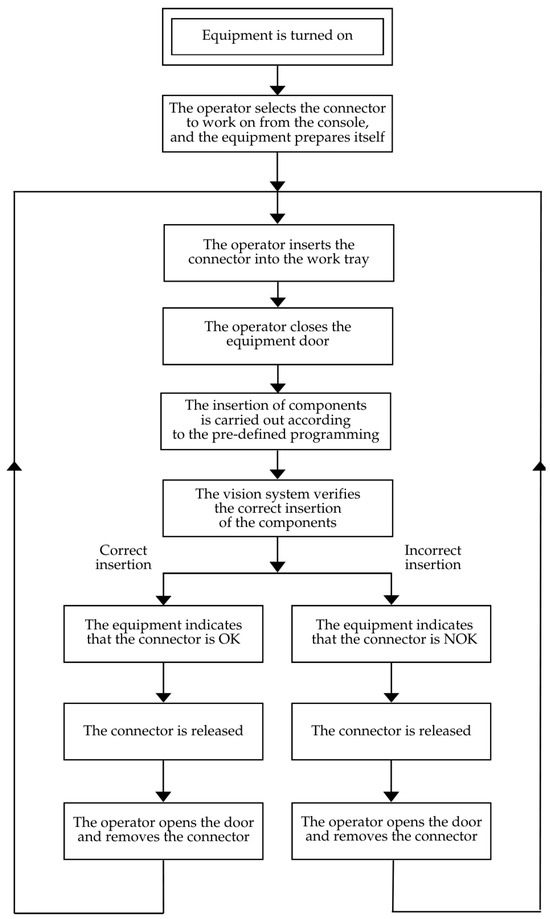
Figure 20.
Equipment’s operating sequence.
To ensure that the operator’s tasks are carried out correctly, detection systems are available that eliminate faults, such as the connector’s presence and door lock detections. The connector’s presence in the workboard is detected, and then it is locked, which guarantees its stability throughout the assembly process. During assembly, the equipment moves its axes, placing the inserter on the different component assembly points. When the inserter is positioned over one insertion point, its operating sequence begins, namely, checking for the presence of a component to be inserted, followed by opening the grip, and finally advancing the insertion cylinder. Next, these steps are reverted in preparation for the next insertion. At the same time, the feeder system remains in operation, ensuring that there is no component shortage in the insertion zone. The power supply system is in operation throughout the entire equipment’s operating period. During the equipment start-up phase, the operator is asked to supply the circular feeder with components. At this stage, the operator puts as many components as possible into the system, ensuring production for a few hours. Inside the circular feeder, the components are orientated and positioned so that they can then be sent to the insertion area. Once the equipment has inserted all the components, the workboard is positioned so that the vision system can check that the components have been correctly assembled, thus starting the process of extracting the connector from the equipment. Once the assembly has been successfully completed, the equipment moves the workboard back to its initial position and releases the connector. At this point, the operator opens the equipment door, removes the finished connector, and begins assembling the next connector.
3.6. Cost Analysis
The final purpose of the proposed equipment is to commercialise it, which makes it appropriate to carry out an analysis of associated costs. Table 4 lists all the points considered in the cost evaluation phase of the equipment, costs that range from the design to the profit forecast associated with its commercialisation.

Table 4.
Costs associated with the equipment.
Labour hours and the profit margin are only defined at the commercialisation stage, at which point an estimate is made depending on the complexity of the equipment and the customer who is going to buy it, so the following is simply an analysis of the costs associated with the purchase of materials, which is the main cost and directly influences the other costs. Table 5 shows approximate figures for the main costs associated with purchasing materials. There is a major expense associated with the acquisition of the main systems, which includes the power supply system. Then, the expenditure is distributed between structural materials, raw materials, pneumatic materials, and electrical materials, showing that the sum of the expenditure on the acquisition of materials is approximately EUR 18,000.

Table 5.
Costs associated with the purchase of materials.
3.7. Subsets Validation
This project was developed with the intention of responding to the needs of a particular client, but due to the negative phase the market has gone through in recent years, the equipment has not yet reached a production stage. However, all the main systems were developed using knowledge acquired by the design company on other projects.
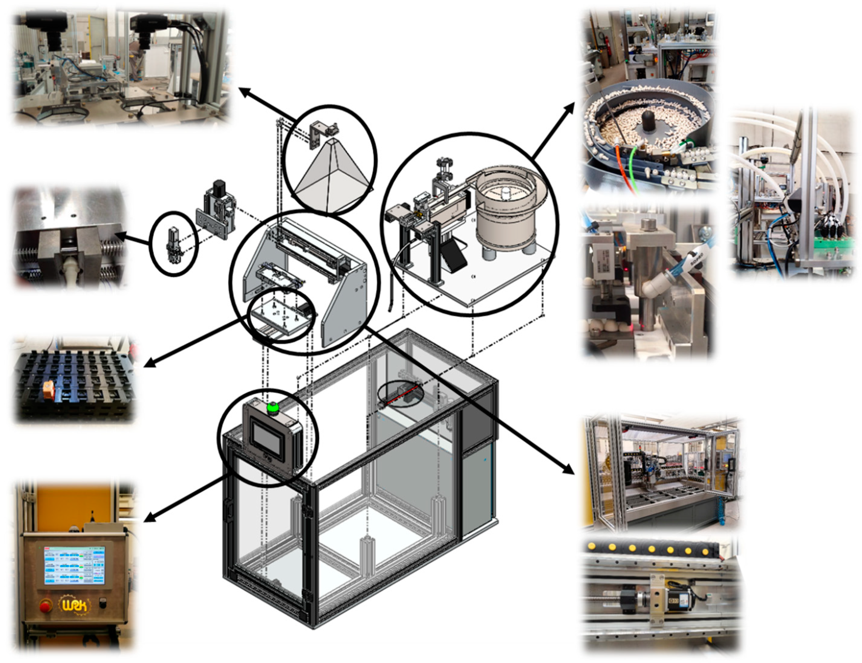
Figure 21 shows application examples of the principles used in the different subsets of the equipment, including the workboard, the inserter, the feeder system, and the axle system. The fact that the project is based on systems that have already been implemented and tested gives confidence in its application, something that is sought after in all the special equipment developed. Although the equipment has not entered a production phase, it can be adapted to other processes in the future. The fact that the equipment has a three-axis system, an artificial vision system and that it is compact allows it to be adapted and transformed into a 3D printer or a laser engraving system, for example, with short design time.
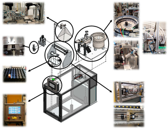
Figure 21.
Examples of system applications.
4. Conclusions
The present work aimed to design semi-automatic equipment that could assemble cabling connectors used in the automotive sector as a replacement for a currently manual process that takes place in an automotive components company to increase its competitiveness. The design was based on principles such as automation, flexibility, high productivity, and competitive pricing. The pre-defined objectives and requirements for this project were fully met:
- Develop equipment that works semi-automatically and uses an inserter, two-component types and one connector type—the equipment works semi-automatically with two component types (pins and seals) and one connector type. There is only human intervention when depositing the components in the circular feeder and placing the connector in the nest of the workboard;
- Implement a component feeder system. The components must be deposited randomly by the operator—a feeder system has been implemented with a circular feeder ready to receive randomly deposited components via a supply hole;
- Design systems to transport components from the feeder system to the inserter—the pick and place and the blower transport the components from the feeder system to the inserter and have been developed taking into account the geometry of the component;
- Create positioning systems for the connector to secure it during the assembly of components (pins and seals)—a workboard was developed consisting of a nest that locks the connector in a given position on the x and y-axes. In addition, the workboard includes latches that lock the connector in a position on the z-axis;
- Apply a system capable of detecting the correct assembly of components in the connector—vision sensor with artificial intelligence was attached to the coordinate mechanism (y-axis);
- Carry out a linear static analysis using FEM—validation of the axle system (y-axis) was accomplished by means of a linear static analysis using the FEM;
- Estimate the costs associated with the equipment—the costs were estimated by categories (main systems, structural material, raw materials, pneumatic material, electrical material, and external services).
The equipment design was successfully accomplished, and the imposed requirements by the client were fulfilled, with significant advantages over the current manual process, such that an alternative to a less efficient manual process can be implemented. Overall, a novel solution was proposed combining automation, modular feeding, assembly mechanisms (which can be adapted for different components, making it flexible for other applications and industries), and a vision system with artificial intelligence. While designed for the automotive sector, the principles of this semi-automatic system, especially the feeder system and the artificial intelligence-driven quality control, can be transferred to other industries (such as electronics, aerospace, or consumer goods), where similar manual processes are still in place. By highlighting the design of a system that is both high-performing and cost-efficient, both the technical and economic challenges of automation in competitive industries like automotive manufacturing are addressed.
Author Contributions
Conceptualisation, P.M.P.C. and J.A.P.P.; methodology, R.D.S.G.C. and F.J.G.S.; software, P.M.P.C.; validation, P.M.P.C. and J.A.P.P.; formal analysis, R.D.S.G.C. and F.J.G.S.; investigation, P.M.P.C.; resources, R.D.S.G.C. and F.J.G.S.; writing—original draft preparation, P.M.P.C. and J.A.P.P.; writing—review and editing, R.D.S.G.C. and F.J.G.S.; supervision, R.D.S.G.C. and F.J.G.S. All authors have read and agreed to the published version of the manuscript.
Funding
This research received no external funding.
Data Availability Statement
The raw data supporting the conclusions of this article will be made available by the authors upon request.
Conflicts of Interest
The authors declare no conflicts of interest.
Abbreviations
| CAD | Computer-Aided Design |
| DfMA | Design for Manufacturing and Assembly |
| DRM | Design Research Methodology |
| DSR | Design Science Research |
| FEM | Finite Element Method |
| FOS | Factor of Safety |
| NOK | Indicator of Non-conformity |
| OK | Indicator of Conformity |
| SRC/CS | Safety Related Parts/Control Systems |
| SWOT | Strengths, Weaknesses, Opportunities, and Threats |
| TRIZ | Theory of Inventive Problem Solving |
| URES | Resultant Displacements |
| V-Model | Verification and Validation |
References
- Klink, G.; Mathur, M.; Kidambi, R.; Sen, K. Contribution of the automobile industry to technology and value creation. Auto Tech Rev. 2014, 3, 18–23. [Google Scholar] [CrossRef]
- Benotsmane, R.; Dudás, L.; Kovács, G. Survey on new trends of robotic tools in the automotive industry. In Proceedings of the Vehicle and Automotive Engineering 3 (VAE 2020), Miskolc, Hungary, 25–26 November 2021; pp. 443–457. [Google Scholar]
- Gabbar, H.A.; Idrees, M. ARSIP: Automated robotic system for industrial painting. Technologies 2024, 12, 27. [Google Scholar] [CrossRef]
- Dulina, L.; Zuzik, J.; Furmannova, B.; Kukla, S. Improving material flows in an industrial enterprise: A comprehensive case study analysis. Machines 2024, 12, 308. [Google Scholar] [CrossRef]
- Lo, W.; Yang, C.-M.; Zhang, Q.; Li, M. Increased productivity and reduced waste with robotic process automation and generative AI-powered IoE services. J. Web Eng. 2024, 23, 53–87. [Google Scholar] [CrossRef]
- Konstantinidis, F.K.; Mouroutsos, S.G.; Gasteratos, A. The role of machine vision in industry 4.0: An automotive manufacturing perspective. In Proceedings of the 2021 IEEE International Conference on Imaging Systems and Techniques (IST), Kaohsiung, Taiwan, 24–26 August 2021; pp. 1–6. [Google Scholar]
- Gajmal, S.S.; Bhatwadekar, S.G. Low cost automation (LCA): A case study. Int. J. Adv. Eng. Glob. Tech. 2014, 2, 172–181. [Google Scholar]
- Salah, B.; Alsamhan, A.M.; Khan, S.; Ruzayqat, M. Designing and developing a smart yogurt filling machine in the Industry 4.0 era. Machines 2021, 9, 300. [Google Scholar] [CrossRef]
- Magalhães, A.; Silva, F.; Campilho, R. A novel concept of bent wires sorting operation between workstations in the production of automotive parts. J. Braz. Soc. Mech. Sci. Eng. 2018, 41, 25. [Google Scholar] [CrossRef]
- Groover, M.P. Automation, Production Systems and Computer-Integrated Manufacturing; Pearson: London, UK, 2016. [Google Scholar]
- Dey, C.; Sen, S.K. Industrial Automation Technologies; CRC Press: Boca Raton, FL, USA, 2020. [Google Scholar]
- Shaloo, M.; Princz, G.; Hörbe, R.; Erol, S. Flexible automation of quality inspection in parts assembly using CNN-based machine learning. Procedia Comput. Sci. 2024, 232, 2921–2932. [Google Scholar] [CrossRef]
- Lowe, B.D.; Hayden, M.; Albers, J.; Naber, S. Case studies of robots and automation as health/safety interventions in small manufacturing enterprises. Hum. Factors Ergon. Man. 2023, 33, 69–103. [Google Scholar] [CrossRef]
- Ford, M. The Lights in the Tunnel: Automation, Accelerating Technology and the Economy of the Future; Acculant Publishing: New York, NY, USA, 2009. [Google Scholar]
- Zhou, Z.; Guo, J.; Zhu, Z.; Guo, H. Uncalibrated visual servoing based on Kalman filter and mixed-kernel online sequential extreme learning machine for robot manipulator. Multimed. Tools Appl. 2024, 83, 18853–18879. [Google Scholar] [CrossRef]
- Ulanov, A. World robot market: Key characteristics and trends. In Digital International Relations; Baykov, A., Zinovieva, E., Eds.; Springer Nature: Singapore, 2023; pp. 235–246. [Google Scholar]
- Kiran, D. Production Planning and Control: A Comprehensive Approach; Butterworth-Heinemann: Oxford, UK, 2019. [Google Scholar]
- Ahmad, R.; Plapper, P. Safe and automated assembly process using vision assisted robot manipulator. Procedia CIRP 2016, 41, 771–776. [Google Scholar] [CrossRef]
- Almoslehy, S.A.M. Design for Profitability: Guidelines to Cost Effectively Manage the Development Process of Complex Products; CRC Press: Boca Raton, FL, USA, 2018. [Google Scholar]
- Pahl, G.; Beitz, W.; Feldhusen, J.; Grote, K.-H. Engineering Design: A Systematic Approach, 3rd ed.; Springer: Berlin, Germany, 2007. [Google Scholar]
- Ulrich, K.T.; Eppinger, S. Product Design and Development, 6th ed.; McGraw-Hill Education: New York, NY, USA, 2016. [Google Scholar]
- Forsberg, K.; Mooz, H.; Cotterman, H. Visualizing Project Management: Models and Frameworks for Mastering Complex Systems; John Wiley & Sons: Hoboken, NJ, USA, 2005. [Google Scholar]
- Pugh, S. Total Design: Integrated Methods for Successful Product Engineering; Addison-Wesley: Boston, MA, USA, 1991. [Google Scholar]
- Altshuller, G. 40 Principles: TRIZ Keys to Technical Innovation; Technical Innovation Center: Worcester, MA, USA, 2002. [Google Scholar]
- Suh, N.P. Axiomatic Design: Advances and Applications; Oxford University Press: New York, NY, USA, 2001. [Google Scholar]
- Peffers, K.; Tuunanen, T.; Rothenberger, M.A.; Chatterjee, S. A design science research methodology for information systems research. J. Manag. Inform. Syst. 2007, 24, 45–77. [Google Scholar] [CrossRef]
- Tojal, M.; Silva, F.J.; Campilho, R.; Pinto, A.; Pinto Ferreira, L. Case-based product development of a high-pressure die casting injection subset using design science research. FME Trans. 2022, 50, 32–45. [Google Scholar] [CrossRef]
- Blessing, L.T.; Chakrabarti, A. DRM: A Design Reseach Methodology; Springer: Berlin/Heidelberg, Germany, 2009. [Google Scholar]
- Boothroyd, G.; Dewhurst, P.; Knight, W.A. Product Design for Manufacture and Assembly; CRC Press: Boca Raton, FL, USA, 2010. [Google Scholar]
- Ehrgott, M.; Gandibleux, X. Multiobjective combinatorial optimization—Theory, methodology, and applications. In Multiple Criteria Optimization: State of the Art Annotated Bibliographic Surveys; Springer: Boston, MA, USA, 2003. [Google Scholar]
- Noura, H.; Theilliol, D.; Ponsart, J.-C.; Chamseddine, A. Fault-Tolerant Control Systems: Design and Practical Applications; Springer Science & Business Media: Berlin/Heidelberg, Germany, 2009. [Google Scholar]
- Feldmann, K.; Müller, B.; Haselmann, T. Automated assembly of lightweight automotive components. CIRP Ann. 1999, 48, 9–12. [Google Scholar] [CrossRef]
- Mo, F.; Rehman, H.U.; Monetti, F.M.; Chaplin, J.C.; Sanderson, D.; Popov, A.; Maffei, A.; Ratchev, S. A framework for manufacturing system reconfiguration and optimisation utilising digital twins and modular artificial intelligence. Robot. Comput. Integr. Manuf. 2023, 82, 102524. [Google Scholar] [CrossRef]
- Mateu-Gomez, D.; Martínez-Peral, F.J.; Perez-Vidal, C. Multi-arm trajectory planning for optimal collision-free pick-and-place operations. Technologies 2024, 12, 12. [Google Scholar] [CrossRef]
- Ling, L.; Zhang, X.; Hu, X.; Fu, Y.; Yang, D.; Liang, E.; Chen, Y. Research on spraying quality prediction algorithm for automated robot spraying based on KHPO-ELM neural network. Machines 2024, 12, 100. [Google Scholar] [CrossRef]
- Costa, M.; Gouveia, R.; Silva, F.; Campilho, R. How to solve quality problems by advanced fully-automated manufacturing systems. Int. J. Adv. Manuf. Technol. 2018, 94, 3041–3063. [Google Scholar] [CrossRef]
- Figueiredo, D.; Silva, F.; Campilho, R.; Silva, A.; Pimentel, C.; Matias, J. A new concept of automated manufacturing process for wire rope terminals. Procedia Manuf. 2021, 51, 431–437. [Google Scholar] [CrossRef]
- Santos, P.R.; Silva, F.J.G.; Campilho, R.D.S.G.; Pinto, G.F.L.; Baptista, A. A novel concept of a conduit transport system. Procedia Manuf. 2019, 38, 848–857. [Google Scholar] [CrossRef]
- Pereira, J.A.P.; Campilho, R.D.S.G.; Silva, F.J.G.; Sánchez-Arce, I.J. Robotized cell design for part assembly in the automotive industry. Proc. Inst. Mech. Eng. Part C 2022, 236, 8807–8822. [Google Scholar] [CrossRef]
- Michalos, G.; Kousi, N.; Karagiannis, P.; Gkournelos, C.; Dimoulas, K.; Koukas, S.; Mparis, K.; Papavasileiou, A.; Makris, S. Seamless human robot collaborative assembly: An automotive case study. Mechatronics 2018, 55, 194–211. [Google Scholar] [CrossRef]
Disclaimer/Publisher’s Note: The statements, opinions and data contained in all publications are solely those of the individual author(s) and contributor(s) and not of MDPI and/or the editor(s). MDPI and/or the editor(s) disclaim responsibility for any injury to people or property resulting from any ideas, methods, instructions or products referred to in the content. |
© 2024 by the authors. Licensee MDPI, Basel, Switzerland. This article is an open access article distributed under the terms and conditions of the Creative Commons Attribution (CC BY) license (https://creativecommons.org/licenses/by/4.0/).

