Abstract
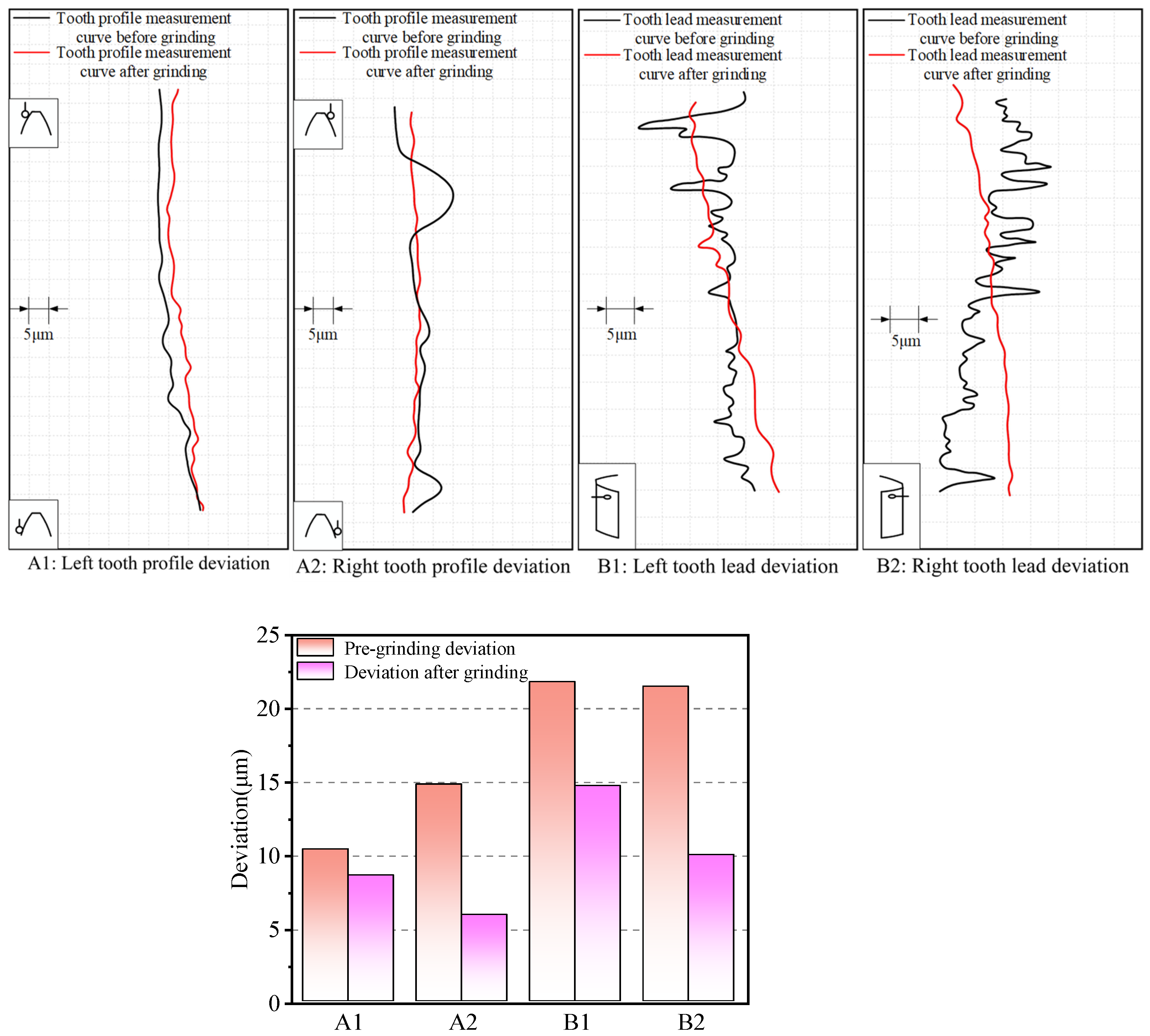
As an important component of mechanical transmission systems, internal splines are widely used in aerospace, industrial equipment, and other fields. However, internal splines are prone to deformation and shrinkage after heat treatment. At present, most internal splines with a pitch circle diameter greater than φ60 mm can be processed and shaped by ordinary corundum grinding wheels, but there is no effective processing method for the shaping of small- and medium-sized internal splines. This paper establishes a single abrasive material removal model; uses Abaqus to simulate three-body free grinding; and analyzes the effects of abrasive rotation angle, rotation speed, and grinding depth on material removal under different conditions. By comparing the tooth lead deviation and tooth direction deviation before and after internal spline grinding, the experimental results show that after ultrasonic vibration grinding, the internal spline tooth profile deviation is reduced by 41.9%, and the tooth direction deviation is reduced by 44.1%, which provides a new processing method for the deformation recovery of internal splines after heat treatment.
1. Introduction
Gear parts are key components of aircraft engine transmission, and the performance of gears directly affects the power output of the engine. Especially for spline gears, the matching accuracy of internal and external splines is crucial to the stability of torque transmission, which in turn affects the overall performance and life of the engine. In order to improve the strength of the internal splines, heat treatment is usually required [1,2,3]. However, the internal spline is prone to large deformation during the heat treatment process. For large internal splines with a pitch diameter greater than φ60 mm, the grinding wheel method can be used for correction [4,5]. For small internal splines with a pitch diameter less than φ60 mm, manual grinding is still the main processing method. However, manual grinding has problems such as poor stability and the fact that it easily causes excessive cross-strip spacing. Therefore, an effective method is urgently needed to solve the processing problems caused by the heat treatment deformation of the internal splines. To this end, this paper proposes to use ultrasonic vibration grinding technology to remove the surface material of the internal splines after heat treatment, so as to improve the processing accuracy and stability and ensure the reliability of the internal splines. Ultrasonic vibration-assisted grinding technology is a high-performance composite processing technology that integrates ordinary grinding and ultrasonic processing. It has developed rapidly in recent years and has shown positive effects in improving the processing efficiency of difficult-to-process materials and improving processing quality [6,7,8]. With the continuous maturity and development of ultrasonic theory, ultrasound has gradually been applied to various fields of production and processing, forming a variety of ultrasonic composite processing methods [9,10].
Wei et al. [11] theoretically modeled the material removal mechanism and dynamics of the grinding process of ultrasonic grinding of spiral bevel gears and comprehensively analyzed the influence of the cavitation effect of abrasive particles and cutting fluid on the tooth surface quality under ultrasonic action. Lv et al. [12] improved the honing process by introducing ultrasonic machining technology, thereby improving the machining accuracy and surface quality of hard gears. From 2010 to 2012, Pandey et al. [13,14,15] of the Indian Institute of Technology conducted a series of ultrasonic-assisted magnetic grinding experiments on AISI 52100 bearing steel (ultrasonic frequency of 20 kHz and amplitude of 3~5 μm), with the goal of reducing the surface roughness of bearing steel to the nanometer level in a shorter time compared with conventional magnetic grinding (MAF). The normal force and cutting torque of the workpiece under the two magnetic grinding methods were measured, respectively. The experimental results showed that both forces were reduced under ultrasonic assistance. In 2014, Wang Yan et al. from Tianjin University of Science and Technology [16] proposed a grinding force and surface roughness prediction model that takes into account the material removal mechanism and, based on this model, explored the mechanism of grinding force reduction and surface roughness formation under ultrasonic action. Venkatesh. et al. [17] carried out ultrasound-assisted abrasive flow (UAAFM) machining on bevel gears, and the results showed that with the prolongation of the grinding time, the tooth face’s surface finish was effectively improved, the micromorphology of the gear tooth surface was significantly improved, and a smooth texture was produced. Singh [18] et al. first proposed the use of ultrasound-assisted electrochemical honing for honing gears by scrubbing the entire surface of the gear teeth. The results showed that ultrasound-assisted electrochemical honing produced better tooth surface roughness than electrochemical honing. Bie et al. [19] proposed a tangential ultrasonic vibration-assisted gear grinding (TUVAGG) system. The vibration system, consisting of a simplified disk and gears, was simulated using the finite element analysis (FEM) method and verified by a resonance measurement test. The grinding temperature and surface roughness decreased by 7.6–25.7% and 8.6–21.8%, respectively, compared with CGG. Zhu et al. [20] carried out ultrasonic grinding processing of gears on a modified rolling inspection machine Y9550, and the results showed that the error of the tooth surface was effectively reduced to a certain extent, the shape and position of the gear contact area were improved, and the tooth surface finish and machining quality were both improved. Han et al. [21] developed a rectangular hexahedron ultrasonic horn to realize ultrasonic vibration of the workpiece and studied ultrasonic-assisted polishing of austenitic stainless steel. Unbounded abrasive was selected, and a path compensation strategy was used. Through orthogonal experiments, it was found that horizontal ultrasonic vibration of the workpiece can reduce polishing force and improve surface roughness. Specific paths can optimize force and quality. The 45-degree oblique crossing path can achieve a maximum reduction of 75.2% in the average polishing force. Song et al. [22] used 18 sets of single-factor ultrasonic cavitation experiments to explore the effects of micro-abrasive and micro-jet impacts on the values of the intrinsic frequency and co-oscillatory amplitude of 6061 aluminum alloys. The results show that the ultrasonic amplitude has a greater effect on the intrinsic frequency than the abrasive content, and the abrasive content has a greater effect on the value of the co-oscillation amplitude, which provides a reference for avoiding the resonance of the workpiece. Yu et al. [23] mainly studied the two-dimensional ultrasonic-assisted polishing of Inconel718 nickel-based alloy. This technology greatly improves the material removal rate and reduces the surface roughness. The material removal rate model is established by analyzing the relevant process parameters, and the experiment shows that the model is in good agreement with the experimental results, which can be used to predict and guide the polishing process. Pei et al. [24] studied the effects of the grinding disc speed, grinding pressure, and abrasive size on the surface quality and removal efficiency of Si3N4 cylindrical rollers via an orthogonal test and finally determined the best combination of process parameters: abrasive size, 2.6 μm; grinding disc speed, 20 r/min; and grinding pressure, 0.15 MPa. Under this condition, the surface roughness is 0.0486 μm, the removal efficiency is 1.20 μm/min, and the surface is smooth without damage. Huang et al. [25] studied the effects of grinding disc speed, grinding pressure, and abrasive particle size on the surface quality and removal efficiency of Si3N4 cylindrical roller by orthogonal test. Finally, the optimal combination of process parameters was determined: abrasive particle size, 2.6 μm; grinding-disc speed, 20 r/min; and grinding pressure, 0.15 MPa. Under this condition, the surface roughness is 0.0486 μm, the removal efficiency is 1.20 μm/min, and the surface is smooth, without damage. Liu et al. [26] experimentally investigated the effects of processing parameters such as the spindle speed, depth of cut, feed rate, and grain size on the grinding force and surface roughness of CFRP in longitudinal torsional ultrasonic vibration grinding. A fitted mathematical model was developed using Box–Behnken design and response surface methodology to analyze the parameter interactions. The Pareto optimal solution was derived through NSGA-II multi-objective optimization, which resulted in a significant improvement in surface quality and a reduction in grinding force.
Based on the above research, this paper proposes a method for the ultrasonic vibration grinding of internal splines for the first time that replaces the manual grinding process of correcting the deformation of internal splines after heat treatment and improves the processing efficiency and tooth profile tolerance.
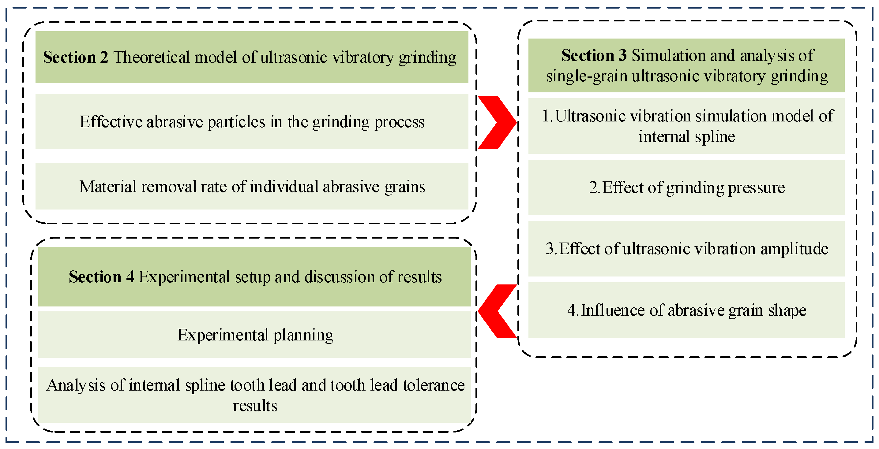
This paper is divided into four sections. As shown in Figure 1, Section 2 studies the material removal of a single abrasive and the total removal rate under the action of all abrasives. In Section 3, a simulation model is established to analyze factors such as grinding pressure and abrasive shape. Section 4 verifies the practical feasibility of ultrasonic vibration grinding technology in internal spline processing through experiments, indicating that this method can effectively improve processing accuracy and surface quality.
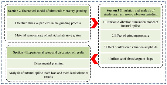
Figure 1.
Logical structure of the paper.
2. Theoretical Model of Ultrasonic Vibratory Grinding
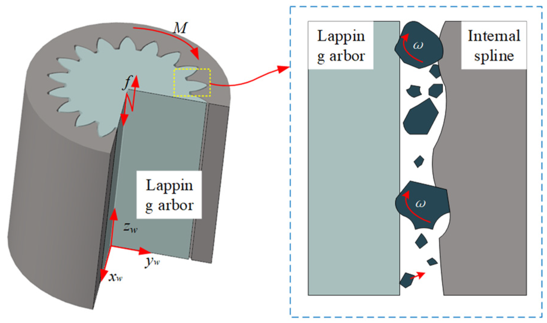
Ultrasonic vibration grinding of internal splines is an advanced processing technology that combines ultrasonic vibration with traditional manual grinding processes. It is mainly used to improve the processing quality and efficiency of internal spline parts. This technology improves the material removal rate and surface roughness by introducing ultrasonic vibration into the grinding process. As shown in Figure 2, high-frequency micro-amplitude vibrations are applied to the grinding rod. These vibrations make the contact between the abrasive grains and the workpiece more uniform and cause the abrasive grains to rotate at a high speed, effectively removing high points on the surface of the internal spline after heat treatment.
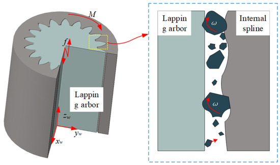
Figure 2.
Schematic diagram of ultrasonic vibratory grinding of internal spline.
2.1. Effective Abrasive Particles in the Grinding Process
During the grinding analysis, the grinding particles are assumed to be spherical. Since the surface of the grinding rod is usually rough, not all particles participate in the grinding process. Effective particles are those that are larger than the grinding rod’s profile height, while ineffective particles are smaller than this height. In fine grinding and polishing, the particle size is usually smaller than the grinding rod’s profile height; therefore, softer grinding rods are used to minimize damage to the internal spline surface. The diameter of the abrasive particles in the abrasive paste is usually between a few microns and tens of microns. These particles are assumed to be spherical, with a radius of r, which is consistent with the size of the abrasive particles removed during the finishing process.
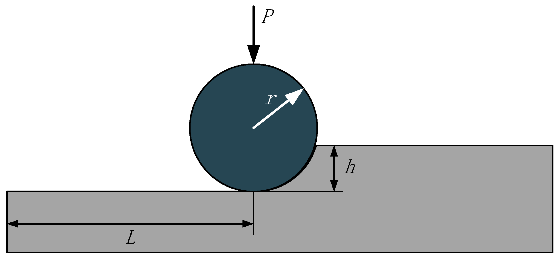
According to the analysis of the mechanism of the occurrence of abrasive grain movement, a certain abrasive grain is pressed into the softer material under the force, P, as in Figure 3, and under the action of ultrasonic vibration, it ploughs a groove with a depth of h and a length of L on the surface of the workpiece.
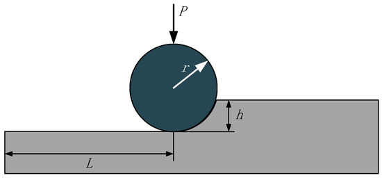
Figure 3.
Grooves made in the material by abrasive grains.
Depth of indentation of abrasive grains at a certain pressure, h:
where is the abrasive cutting depth (μm); is the concentration of abrasive grains; is the grinding pressure (MPa); is the Vickers microhardness of 9310 (GPa); is the grain size of abrasive grains (μm); is the modulus of elasticity of 9310 (GPa); is the modulus of elasticity of the abrasive (GPa); is the Poisson’s ratio of 9310; and is the Poisson’s ratio of the abrasive.
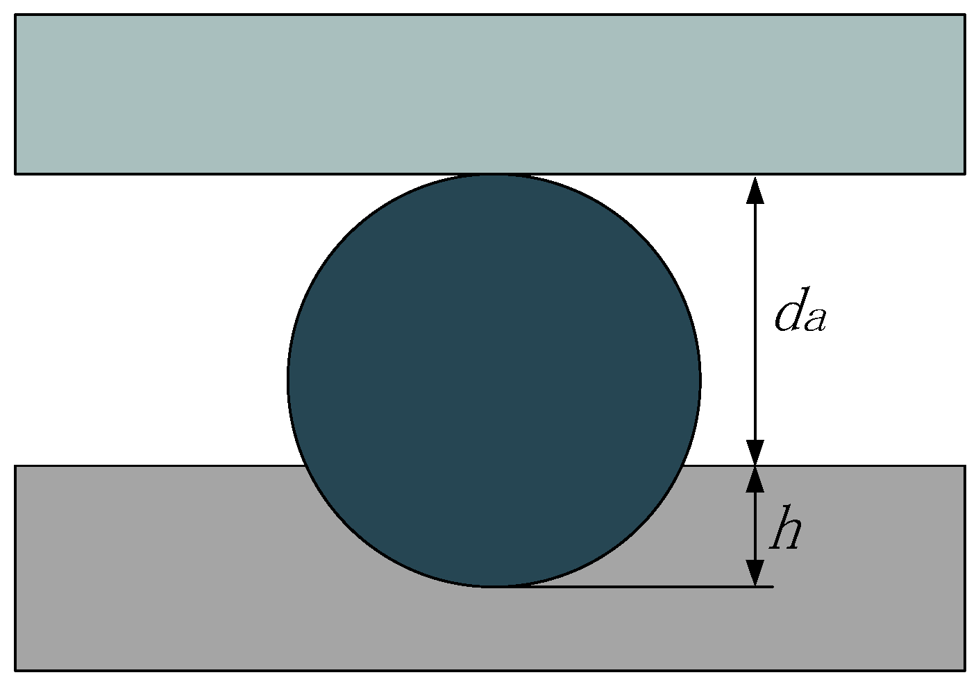
From Figure 4, it can be seen that the size of the effectively ground particles at this point must not be less than the following:
where is the large particle diameter in the abrasive particles, and is the depth of cut for large particles.
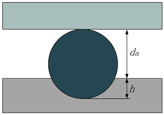
Figure 4.
Effective grinding particle diameter.
Suppose that the size of the grinding particles obeys a normal distribution:
Then, the probability of the presence of effective abrasive grains is as follows:
where is the effective number of abrasive particles, is the total number of abrasive particles, is the average abrasive particle size, and is the minimum abrasive particle size.
Total number of abrasive grains:
where is the volume of abrasive paste present between the abrasive plate and 9310, is the concentration of abrasive particles in the abrasive.
where is the area of the grinding disk.
The effective number of abrasive grains, N, can be obtained from Equations (2) and (5)–(7) as follows:
2.2. Material Removal Rate of Individual Abrasive Grains
According to the normal distribution curve of grinding particles and national standards, the proportion of large particles and very small particles is very small. Therefore, it is assumed that the particles contributing to the grinding process have a size that can be determined by Formula (3).
The depth of cut of the abrasive grain at this point in time under a certain pressure, ha, is as follows:
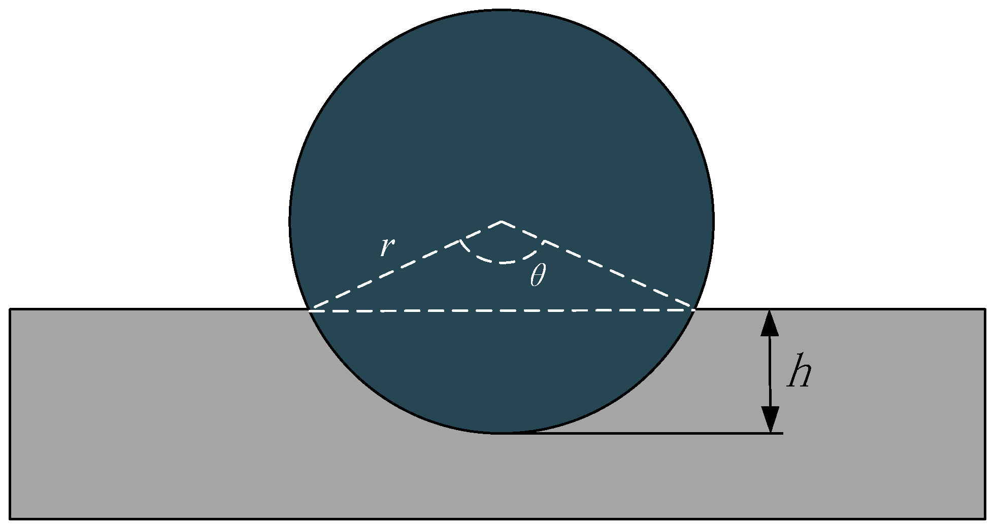
The cutting volume of a single abrasive is shown in Figure 5.
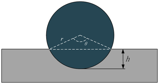
Figure 5.
Cutting cross-sectional area of a single grit.
The cutting arc corresponds to the center angle of the circle:
The fan-shaped area is as follows:
The area of the triangle is as follows:
The effective cutting area of the abrasive grain is as follows:
The removal rate of single abrasive particles is as follows. Let the grinding grits move under ultrasonic vibration for a distance, , and then the rolling cutting volume of a single grit is :
Material removal-rate formula:
where represents the density of the inner spline material, N represents the number of effective abrasive grains, and represents the volume of the inner spline removed by a single abrasive grain per unit time.
3. Simulation and Analysis of Single-Grain Ultrasonic Vibratory Grinding
3.1. Ultrasonic Vibration Simulation Model of Internal Spline
3.1.1. Two-Dimensional Model
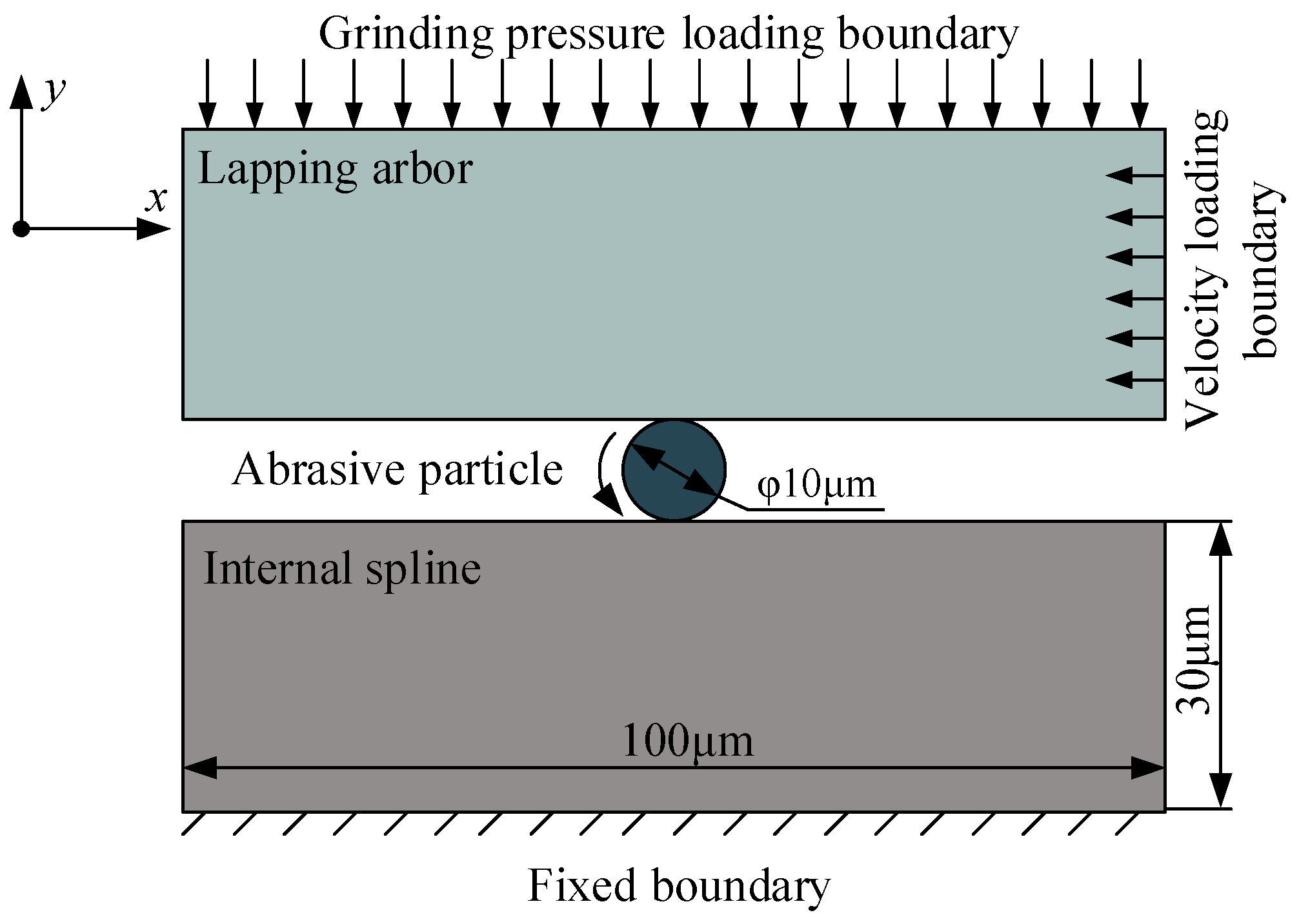
In this study, a simplified two-dimensional plane strain finite element model of the grinding process was established using the finite element software Abaqus 2020, as shown in Figure 6.
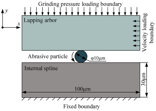
Figure 6.
Finite element model.
The finite element model consists of three parts: grinding rod, abrasive grain, and workpiece. Unlike the actual grinding process, only one abrasive grain is used in the model to analyze the movement and force of a single abrasive grain during the grinding process. Considering that the material removal on the workpiece surface during the grinding process is mainly through the mechanical action of the abrasive grains in the abrasive paste, the effect of the fluid in the abrasive paste is ignored in the finite element analysis. At this time, the grinding rod, abrasive grain, and workpiece are in solid contact.
3.1.2. Material Constitutive Parameters
The basic parameters of the abrasive rod, abrasive grains, and internal spline are shown in Table 1, and the plastic stress–strain curves were modelled using the Johnson–Cook model [27] with the following expressions:
where σ is the flow stress, i.e., the real-time yield stress of the material after the material enters the plastic state (MPa); and are the equivalent strain rate and the reference strain rate, and the reference strain rate is generally taken to be 1 when the strain rate is large; and are the room temperature and the melting point of the material, respectively; T is the real-time maximum working temperature; and A, B, C, m, and n are the J-C intrinsic parameters, where A is the initial yield stress, B is the strain-strengthening coefficient, C is the strain rate-strengthening coefficient, m is the temperature thermal-softening coefficient, and n is the work-hardening index. The material parameters are shown in Table 2.

Table 1.
Material parameters.

Table 2.
Initial values of 9310 steel and QT400 intrinsic parameters.
Since the grinding paste is continuously replenished during the grinding process, and the contact area of a single diamond abrasive during the cutting process is very small, the heat dissipation efficiency is high. Therefore, there is no need to consider the effect of temperature changes on the cutting of 9310 steel with a single diamond abrasive.
3.2. Effect of Grinding Pressure
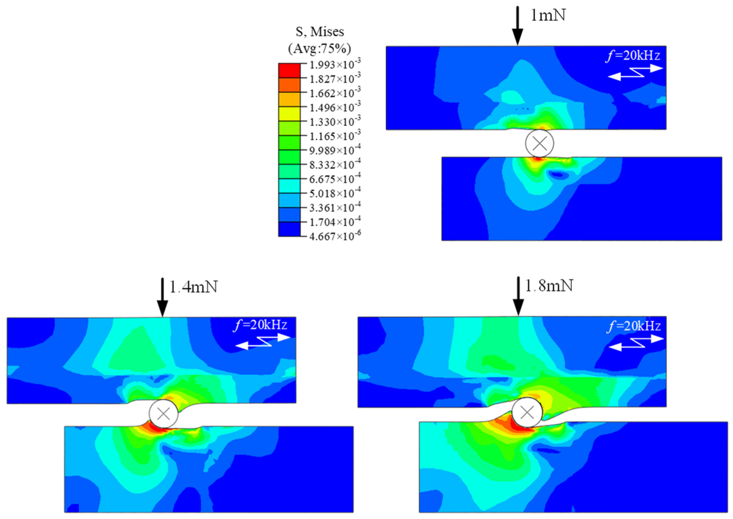
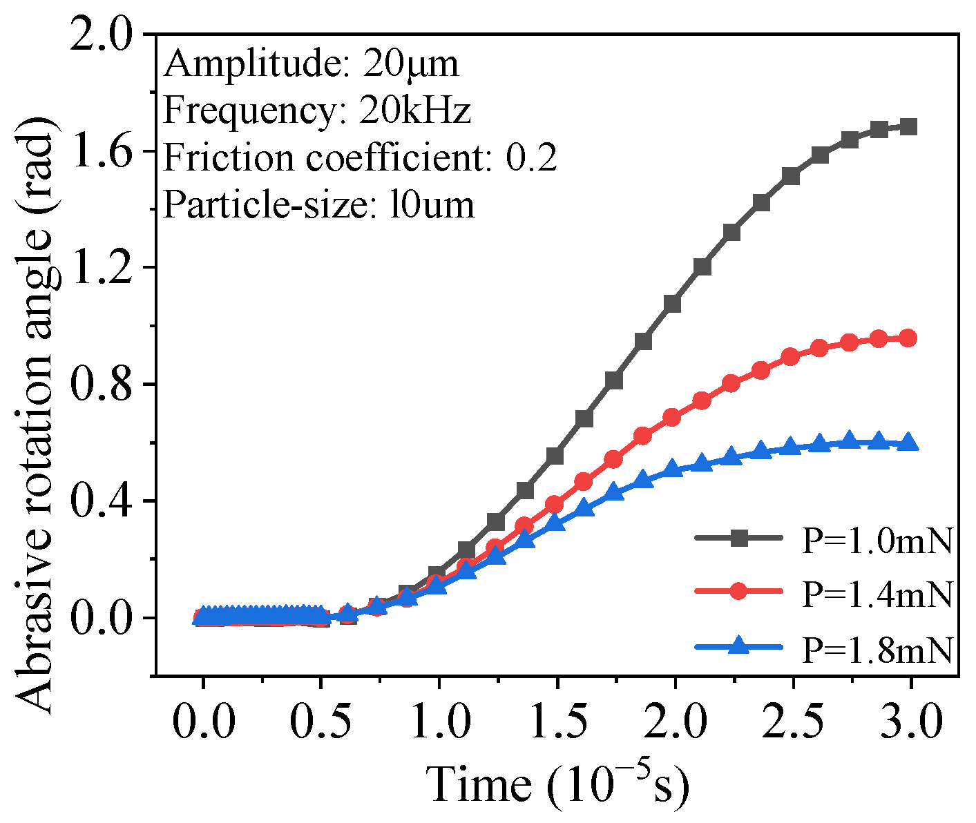
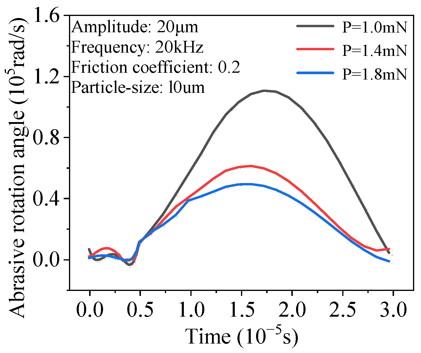
In Figure 7, which shows the equivalent force distribution of the abrasive rod and internal spline under different abrasive pressures, it can be observed that varying abrasive pressures affect the rolling behavior of the abrasive grains at a constant ultrasonic vibration frequency of 20 kHz. As shown in Figure 8, the rolling angle of the abrasive grains decreases as the pressure increases from 1 mN to 1.8 mN. This occurs because, with increasing pressure, the surface deformation of the workpiece and the grinding rod in contact with the abrasive grain also increases. Consequently, material gradually accumulates in front of and behind the rolling abrasive grain, increasing the resisting moment during rolling and resulting in a smaller rotation angle. As a result, the angular velocity of the abrasive grains gradually decreases, as depicted in Figure 9.
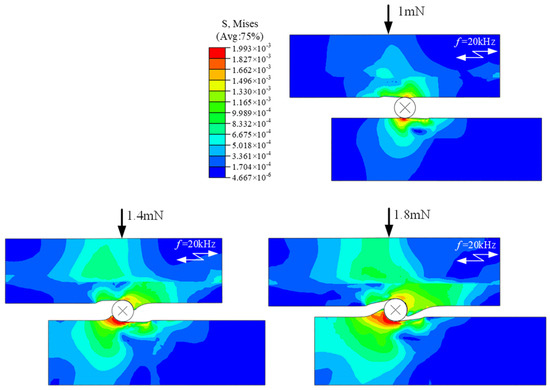
Figure 7.
Equivalent force distribution of the grinding rod and internal spline at different grinding pressures.
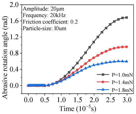
Figure 8.
Variation in the angle of rotation of abrasive grains with time under different pressures.
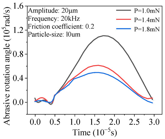
Figure 9.
Variation in angular velocity of abrasive grains with time at different pressures.
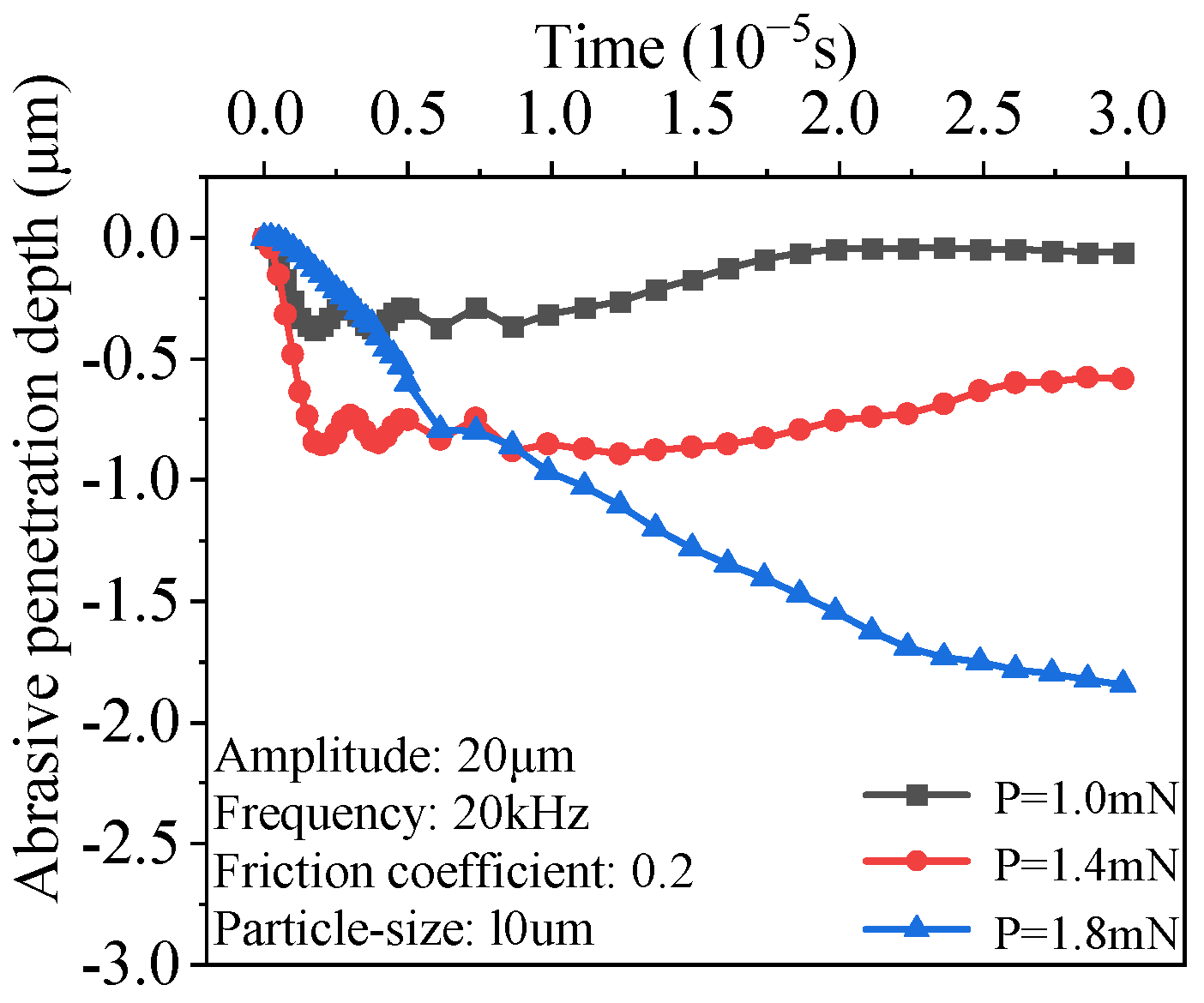
As for the grinding depth, as shown in Figure 10, when the grinding pressure is 0.8 mN, the maximum grinding depth is 0.379 μm. When the grinding pressure increases to 1.6 mN, the maximum grinding depth rises to 1.844 μm. Although the grinding depth increases with the increase in grinding pressure, after grinding, the surface roughness, also increases accordingly.
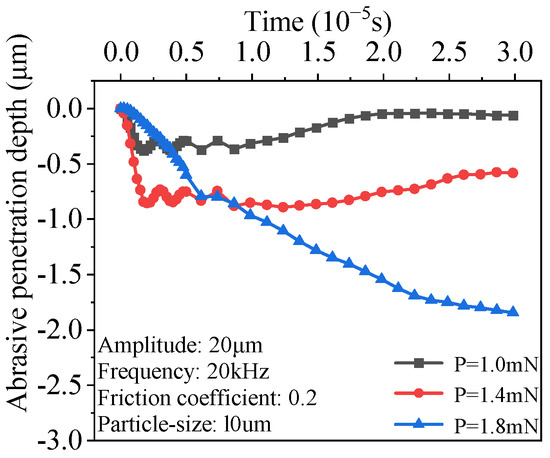
Figure 10.
Variation in grinding depth of abrasive grains with time at different pressures.
3.3. Effect of Ultrasonic Vibration Amplitude
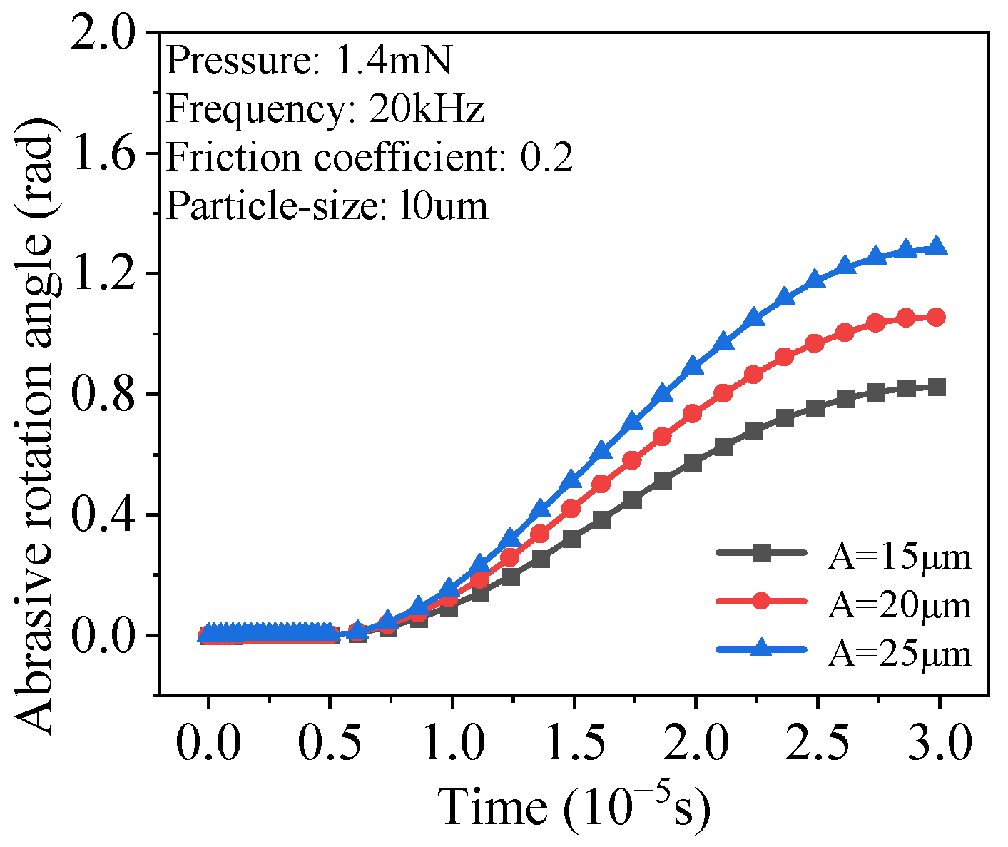
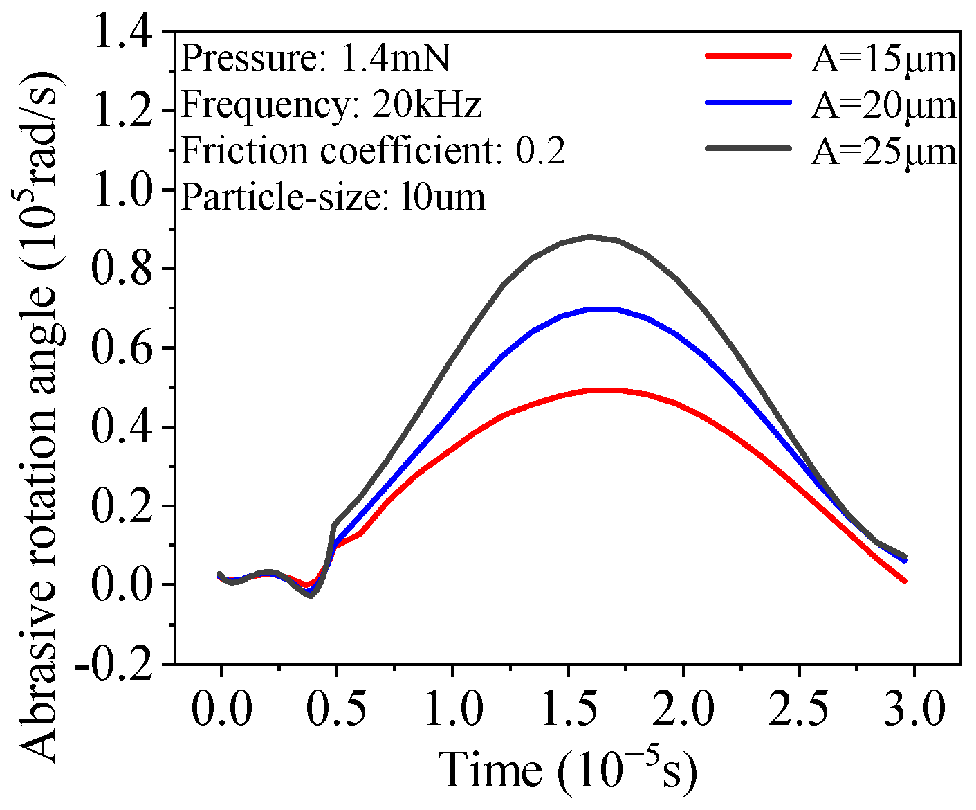
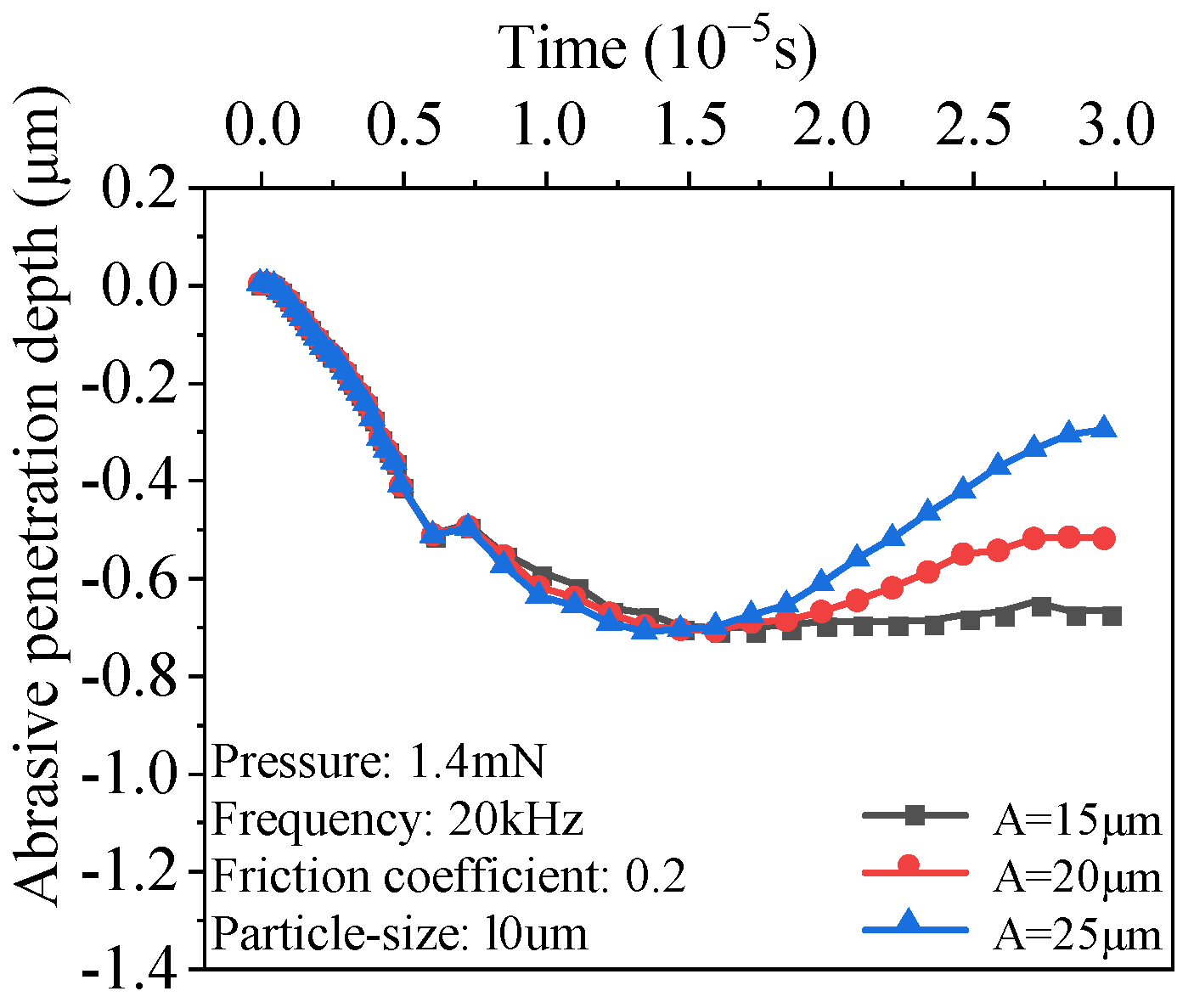
Figure 11 shows the effect of different ultrasonic amplitudes on the rolling behavior of abrasive particles at a constant ultrasonic vibration frequency of 20 kHz. As the amplitude increases from 15 μm to 25 μm, the rotation angle of the abrasive particles gradually increases. Figure 12 shows that when the ultrasonic amplitude reaches 25 μm, the rotation angle is the largest. Figure 13 shows that the displacement of the abrasive particles in the y-axis direction changes with the increase in the amplitude. As the amplitude increases, the abrasive particles obtain greater kinetic energy and impact force during the grinding process, enhancing their cutting effect on the material. However, when the amplitude reaches 20 μm and 25 μm, excessive ultrasonic vibration will cause local plastic deformation or extrusion of the material in front of the abrasive particles, resulting in material accumulation. Although the energy obtained by the abrasive particles increases with the increase in the amplitude, this will also cause the material in front of the abrasive particles to be subjected to a greater reaction force, limiting the effective cutting depth. Therefore, at higher amplitudes, the abrasive drop depth is equivalent to the drop depth at 15 μm, because the material accumulation offsets part of the kinetic energy of the abrasive particles in the y-axis direction, resulting in a consistent drop depth. Nevertheless, higher amplitudes cause the abrasive particles to exert greater impact force and energy on the workpiece surface. Although material buildup can affect some depths of cut, increased amplitude helps the particles retain higher kinetic energy, preventing them from embedding in the workpiece and reducing clogging caused by material buildup.
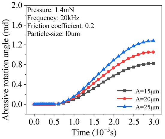
Figure 11.
Variation in rotation angle of abrasive grains with time at different ultrasonic amplitudes.
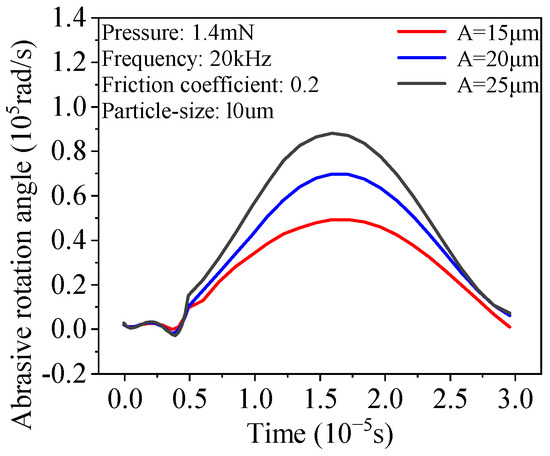
Figure 12.
Variation in the angular velocity of abrasive grains with time at different ultrasonic amplitudes.
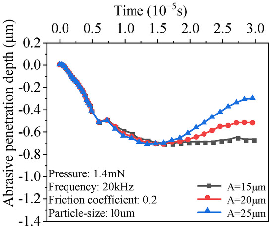
Figure 13.
Variation in grinding depth of abrasive grains with time at different ultrasonic amplitudes.
3.4. Influence of Abrasive Grain Shape
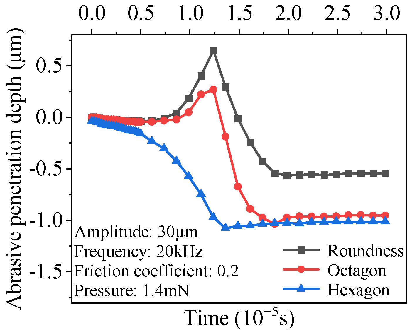
To analyze the effect of different abrasive grain shapes, hexagonal, octagonal, and circular abrasive grains were investigated, all with a height of 10 μm. When using hexagonal and octagonal abrasive grains, their relatively sharp angles cause deformation of the indentation morphology when the abrasive grains roll on the workpiece surface. The larger the angle, the more obvious the indentation, as shown in Figure 14. In the simulation, the y-direction displacement of the node with the largest grinding depth was extracted. The maximum depth of the hexagonal indentation was observed to be 1.08 μm, while the workpiece surface remained relatively flat, without large undulations, after rolling with circular abrasive grains. Grinding with abrasive grains with blunted shapes results in poor surface roughness.
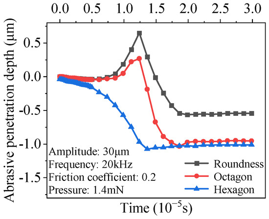
Figure 14.
Variation in abrasive depth with time for different abrasive grain shapes.
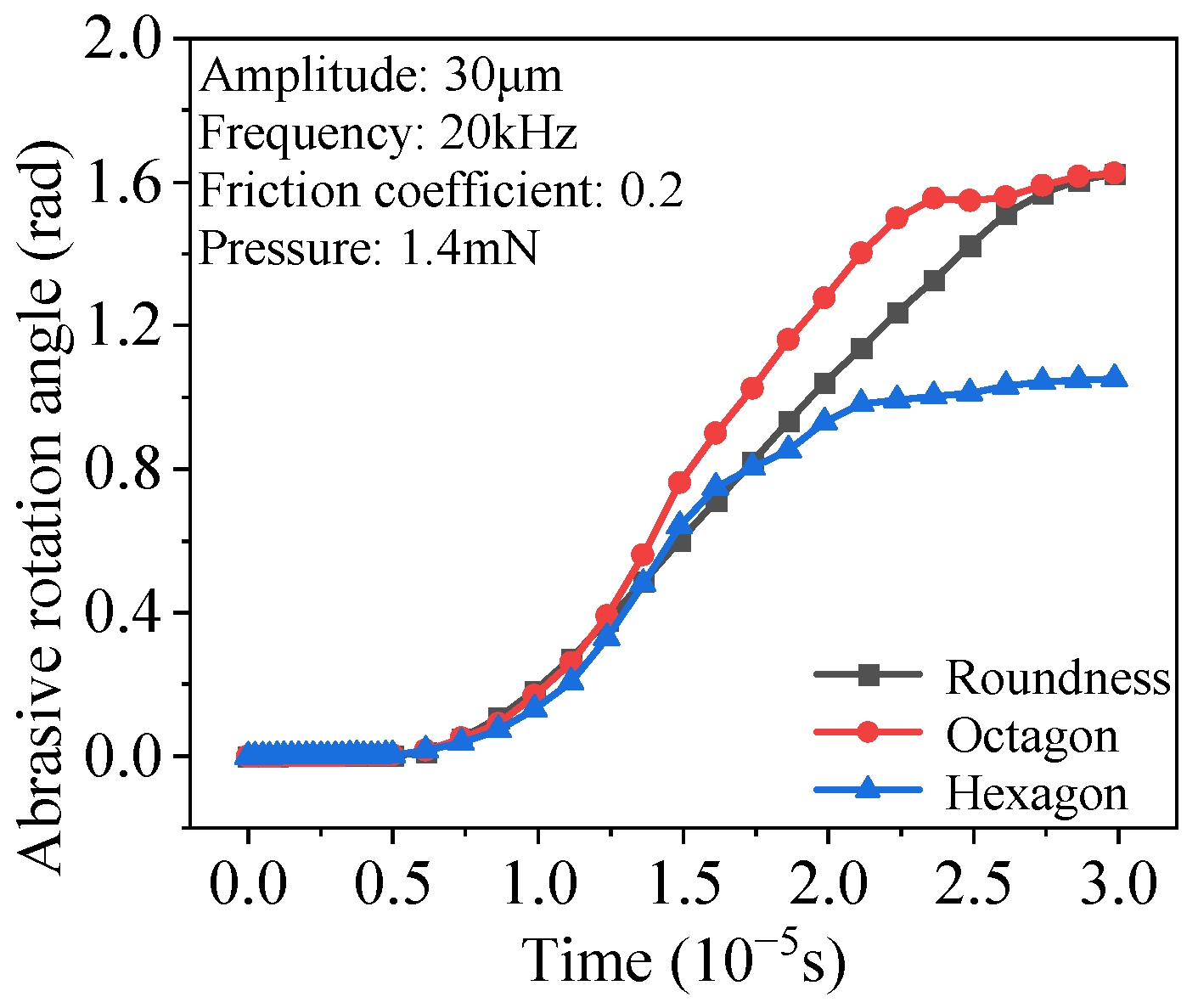
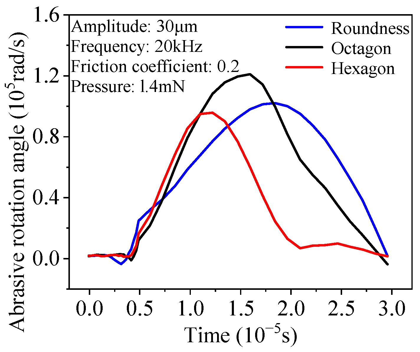
The rotation angles of abrasive grains of different shapes under 20 kHz ultrasonic vibration were also analyzed. Figure 15 shows that the rotation angles of octagonal grains are larger than those of hexagonal grains because, under the same pressure, the rolling motion of hexagonal grains quickly turns into a sliding motion, while the octagonal grains remain in a rolling state. Figure 16 shows that the angular velocities of rotation are different for different particle shapes, and the angular velocity of hexagonal particles approaches zero at 0.02 ms.
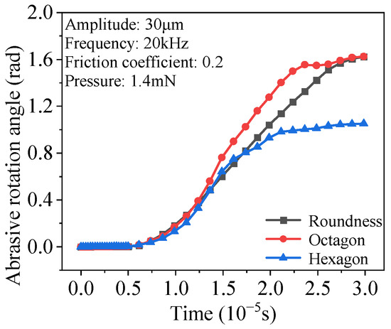
Figure 15.
Variation in the angle of rotation of abrasive grains with time under different grain shapes.
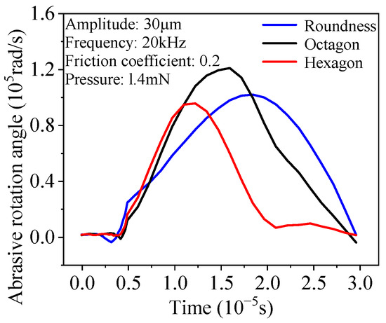
Figure 16.
Variation in angular velocity of abrasive grain with time for different abrasive grain shapes.
3.5. Effect of Coefficient of Friction
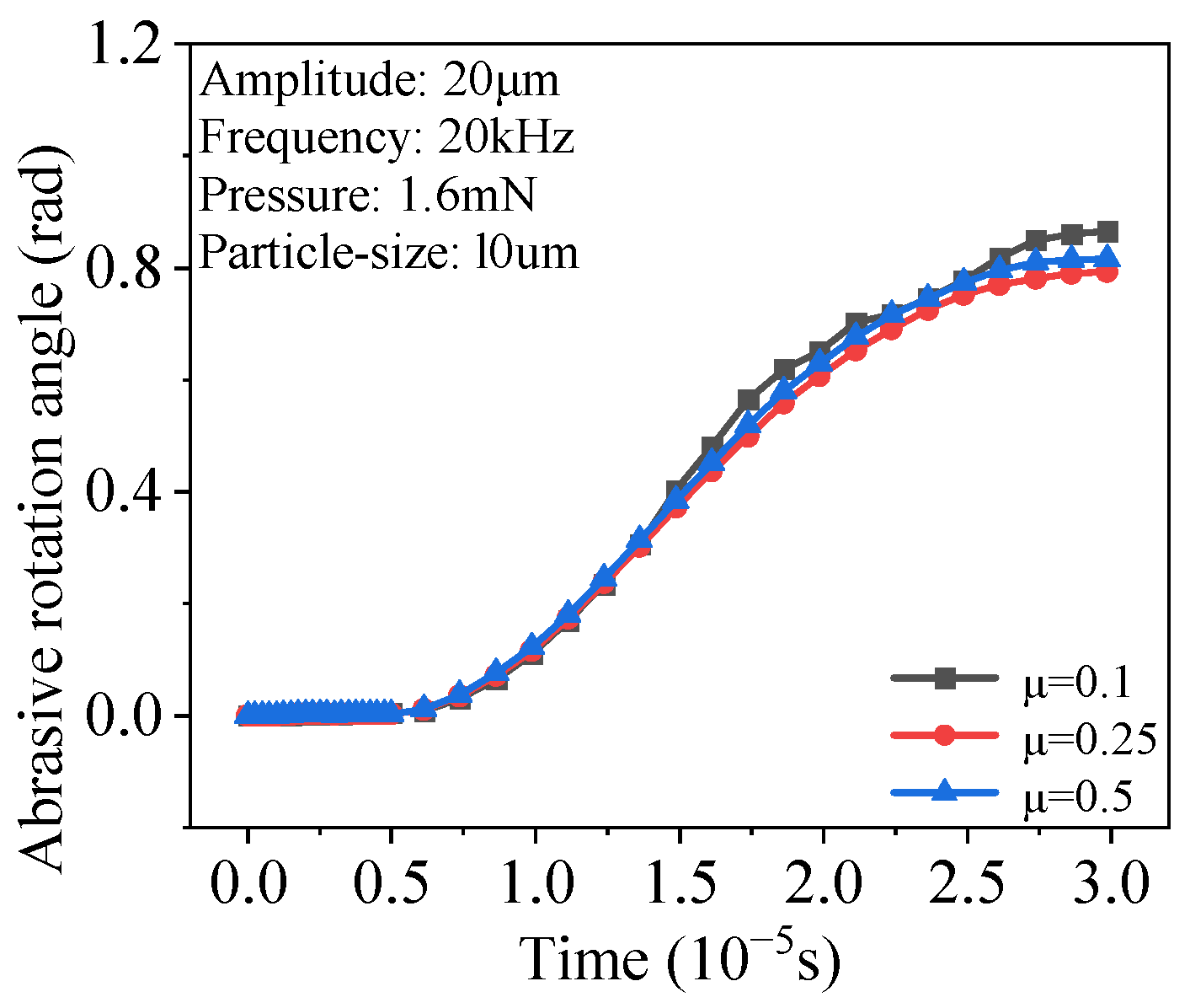
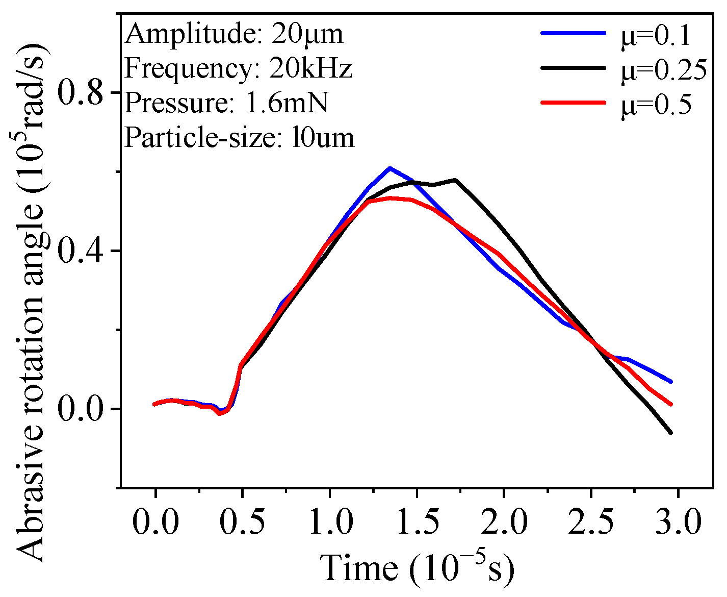
Under the conditions of constant 20 kHz ultrasonic vibration frequency and 1.6 mN grinding force, the effect of changing the friction coefficient between the workpiece and the abrasive grain on the grinding process was studied. As shown in Figure 17 and Figure 18, the abrasive grain bar began to move at 0.01 ms, and relative speed and friction were generated between the abrasive grain, the abrasive grain bar, and the workpiece. Over time, the friction angle under different friction coefficients remained relatively constant. However, the rotation angle of the abrasive grain was the largest when the friction coefficient was 0.1, followed by the friction coefficient of 0.5. This is because when the friction coefficient is 0.1, the sliding friction is not enough to offset the torque generated by the movement of the abrasive grain bar, allowing the abrasive grain to roll freely. When the friction coefficient is 0.5, although the sliding friction is large, the relative movement between the grinding rod, the abrasive grain, and the internal spline is restricted, and the abrasive grain releases energy by rolling, and the rotation angle is large. When the friction coefficient is 0.3, the abrasive grain is in a state between sliding and rolling, and the rotation angle is small.
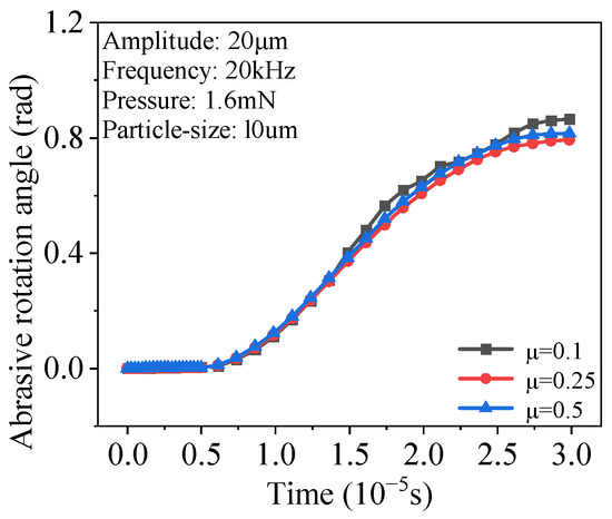
Figure 17.
Variation in the angle of rotation of abrasive grains with time for different friction coefficients.
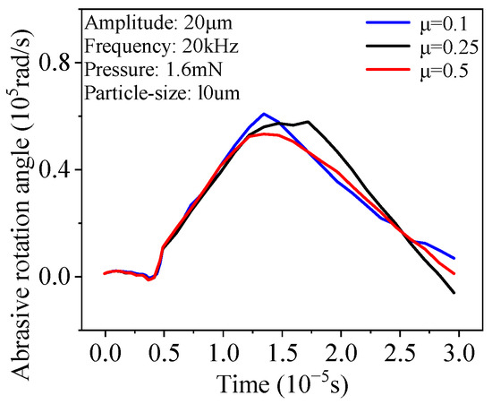
Figure 18.
Variation in angular velocity of abrasive grains with time for different friction coefficients.
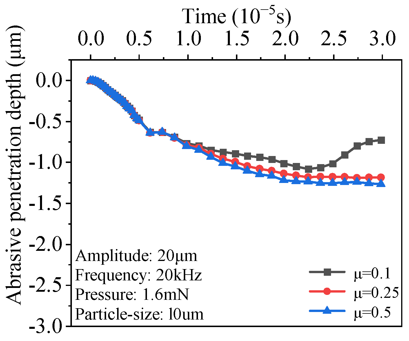
Figure 19 shows that the grinding depth is the largest when the friction coefficient is 0.3. This is because the friction coefficient increases, and the resistance encountered by the abrasive during the grinding process increases, causing the abrasive to embed deeper into the workpiece surface. The greater the friction coefficient, the greater the resistance, forcing the abrasive to embed deeper into the material, causing the abrasive to remove more material in each grinding process.
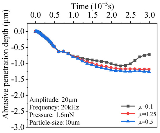
Figure 19.
Variation in abrasive grain grinding depth with time for different friction coefficients.
4. Experimental Setup and Discussion of Results
4.1. Experimental Planning
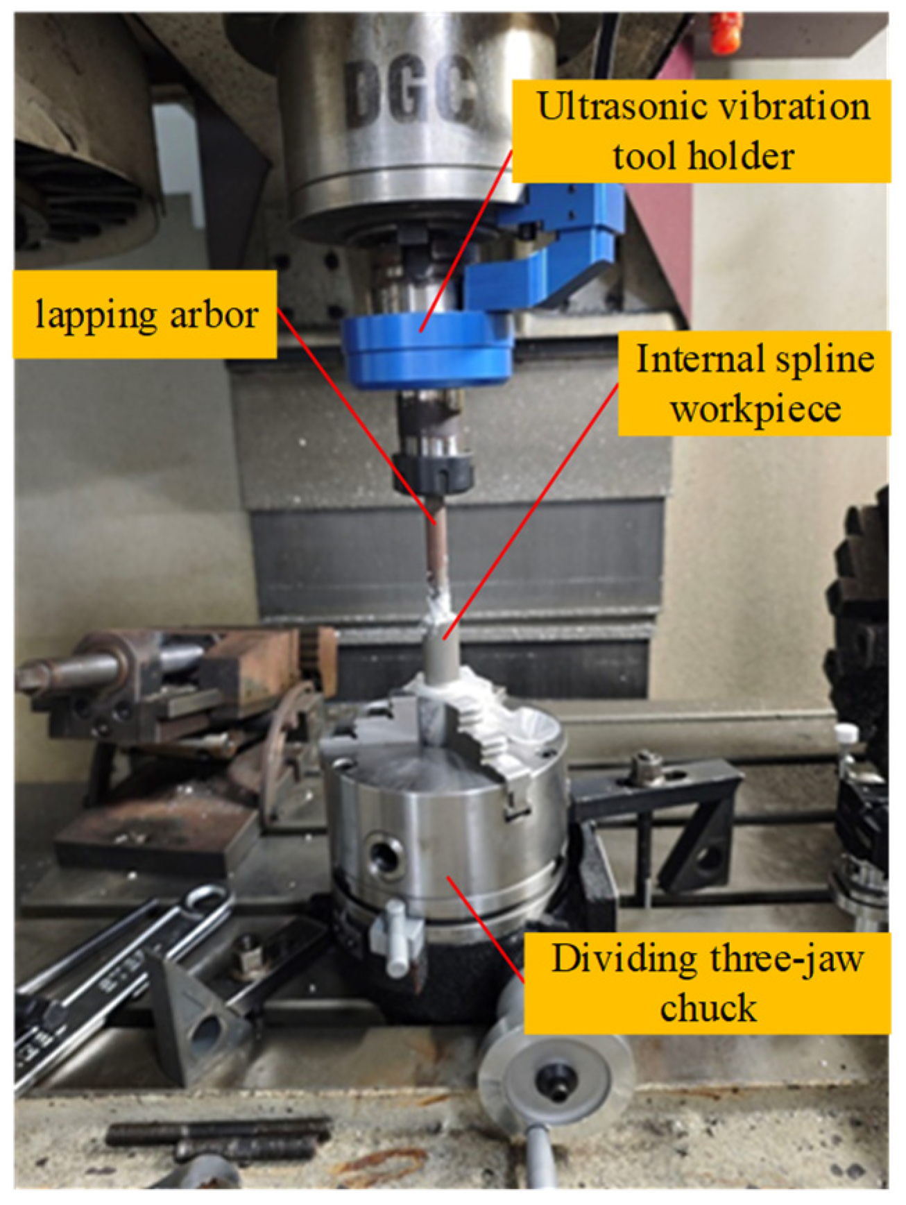
The ultrasonic vibration system consists of an ultrasonic generator, an ultrasonic transducer, a horn, and a grinding rod. The setup of the ultrasonic vibration grinding system is shown in Figure 20. The grinding rod is connected to the ultrasonic vibrator through a spring chuck, and the vibrator is mounted on the machine tool using a BT40 taper shank. The internal spline specimen has 12 teeth, a module of 1, a pressure angle of 30°, and a length of 22 mm. A customized SiC grinding paste is used as the grinding medium.
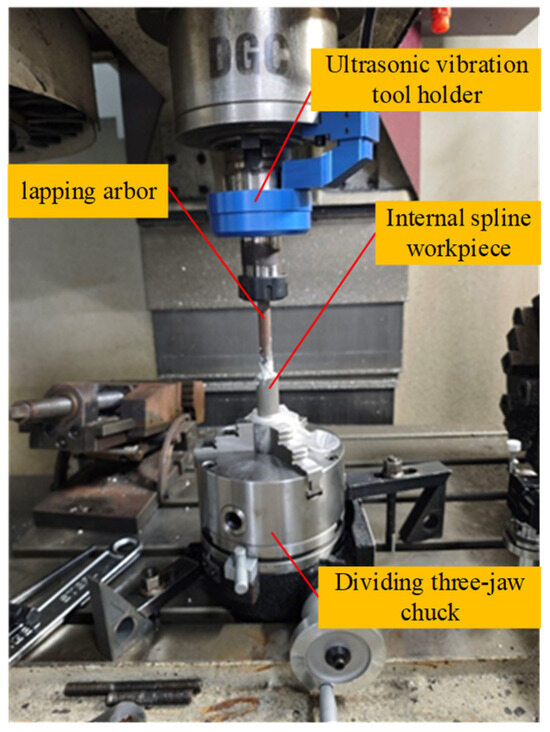
Figure 20.
Experimental site of ultrasonic vibration grinding of internal spline.
The ultrasonic vibration grinding device includes a graduated three-jaw chuck that allows the angle to be adjusted to change the grinding pressure. The internal spline tooth lead deviation and tooth direction deviation are used as indicators. Ultrasonic vibration grinding is performed for 10 min with the power set to 60% for the experiment. The parameters of the internal spline before and after grinding are compared.
After grinding, the grinding paste on the surface of the internal spline is cleaned with a cleaning fluid. Subsequently, the tooth lead and tooth direction deviations are measured using a P100 instrument produced by Klingelnberg.
4.2. Analysis of Internal Spline Tooth Lead and Tooth Lead Tolerance Results
As shown in Figure 21, the black lines represent the deviations of the tooth profile and tooth lead measured by P100, which represent the deviations before and after grinding, respectively. As can be seen from the figure, the profile after grinding is relatively smooth, and the deviations of the tooth profile and tooth lead are significantly reduced. These deviations directly affect the meshing accuracy with the external spline. The experimental results show that ultrasonic vibration grinding can effectively reduce these deviations to varying degrees.
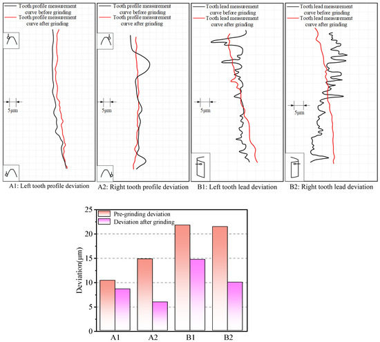
Figure 21.
Deviation of tooth profile and tooth lead of tooth surface.
The ultrasonic vibration grinding process enhances the uniformity of the contact between the grinding medium and the internal spline surface through high-frequency vibration. This improves the overall profile accuracy of the tooth profile and tooth lead. It is worth noting that the areas with larger deviations before grinding have a greater reduction in deviation after grinding. This may be because these areas are subjected to greater impact forces during the grinding process, resulting in more significant material removal and a rapid reduction in deviations.
The results show that ultrasonic vibration grinding provides a more effective finishing treatment for surfaces with larger irregularities. The process increases the kinetic energy of the grinding medium through high-frequency vibration and more effectively removes material from the surface of the internal spline. Therefore, the uniform finishing of the internal spline surface can significantly reduce the pitch and tooth profile deviations, making the tooth surface shape closer to the ideal profile. This improvement is crucial to improving the performance of internal splines in practical applications.
5. Conclusions
The material removal model of the internal spline material surface and the number of effective abrasive particles during the grinding process were established. Through the simulation and experimental study of abrasive material removal during ultrasonic vibration grinding of internal splines, the following conclusions were obtained:
- (1)
- The established abrasive material removal simulation model was used to study the surface removal of internal spline materials during abrasive grinding under different grinding parameters by three-body grinding, which has certain guiding significance for actual machining.
- (2)
- The grinding pressure has the greatest influence among the simulation parameters. The greater the pressure, the faster the material removal on the internal spline surface and the higher the efficiency of the grinding process. The second most influential factor is the shape of the abrasive particles. In actual processing, the use of more angular abrasive particles is helpful to improve the grinding and shaping efficiency of internal splines.
- (3)
- In the experiment, by measuring the tooth profile deviation and tooth direction deviation after ultrasonic vibration grinding, the tooth profile deviation was reduced by 41.9%, and the tooth direction deviation was reduced by 44.1%, proving that ultrasonic vibration grinding can make the internal spline meet the requirements after heat treatment.
Author Contributions
Conceptualization, Z.Z., Q.L., and S.Z.; methodology, Z.Z. and Q.L.; software, S.Z.; validation, Z.Z.; formal analysis, Q.L. and L.Z.; investigation, B.S.; resources, Z.Z., S.Z., and Q.L.; data curation, B.S.; writing—original draft preparation, Z.Z.; writing—review and editing, S.Z., L.Z., B.S., and J.H.; visualization, S.Z.; supervision, Z.Z.; project administration, Z.Z.; funding acquisition, Z.Z. All authors have read and agreed to the published version of the manuscript.
Funding
This research was supported by the AECC Harbin Dongan Engine Co., Ltd. (project number: 6900016572), and the AECC Hunan Aviation Powerplant Research Institute (project number: TC230Y04S-12).
Data Availability Statement
The author has not obtained data-disclosure permission.
Conflicts of Interest
Author Zemin Zhao was employed by the company AECC Harbin Dongan Engine Co., Ltd. The remaining authors declare that the research was conducted in the absence of any commercial or financial relationships that could be construed as a potential conflict of interest.
References
- Kim, J.-R.; Yoon, S.-H.; Jung, Y.-C.; Suh, C.-H.; Kwon, T.-H. A Study on the Thermal Deformation Simulation of Spur Gear According to the Heat Zones in Heat Treatment Process. J. Korean Soc. Manuf. Process Eng. 2020, 19, 60–66. [Google Scholar] [CrossRef]
- Li, X.; Ju, D.; Cao, J.; Wang, S.; Chen, Y.; He, F.; Li, H. Effect of Transformation Plasticity on Gear Distortion and Residual Stresses in Carburizing Quenching Simulation. Coatings 2021, 11, 1224. [Google Scholar] [CrossRef]
- Yang, J.; Zhang, Z.; Wang, S.; Wu, J. Tooth Surface Deviation Analysis for Continuous Generation Grinding of Internal Gears. Appl. Sci. 2024, 14, 6551. [Google Scholar] [CrossRef]
- Li, G.; Bie, W.; Zhao, B.; Chen, F.; Zhao, C.; Zhang, Y. Ultrasonic Assisted Machining of Gears with Enhanced Fatigue Resistance: A Comprehensive Review. Adv. Mech. Eng. 2022, 14, 168781322210828. [Google Scholar] [CrossRef]
- Yanase, Y.; Komori, M.; Ochi, M. Grinding of Internal Gears by Setting a Large Crossed-Axes Angle Using a Barrel-Shaped Grinding Wheel. Precis. Eng. 2018, 52, 384–391. [Google Scholar] [CrossRef]
- Li, H.; Chen, T.; Li, H.; Zhang, Y. Influence of Ultrasonic Vibration on Machining Quality of down/up Grinding in Ultrasonic Vibration Assisted Grinding of Silicon Carbide. Mach. Sci. Technol. 2023, 27, 1–19. [Google Scholar] [CrossRef]
- Maroju, N.K.; Kundhojalla, S.M.; Kesherwani, A.K.; Pasam, V.K. Finite Element Modeling of Multi-Grit Stochastic Grinding Tool for Vibration-Assisted Surface Grinding of Ti6Al4V. J. Mater. Eng. Perform. 2024. ahead of print. [Google Scholar] [CrossRef]
- Yang, Z.; Zhu, L.; Zhang, G.; Ni, C.; Lin, B. Review of Ultrasonic Vibration-Assisted Machining in Advanced Materials. Int. J. Mach. Tools Manuf. 2020, 156, 103594. [Google Scholar] [CrossRef]
- Kurniawan, R.; Kiswanto, G.; Ko, T.J. Surface Roughness of Two-Frequency Elliptical Vibration Texturing (TFEVT) Method for Micro-Dimple Pattern Process. Int. J. Mach. Tools Manuf. 2017, 116, 77–95. [Google Scholar] [CrossRef]
- Lotfi, M.; Amini, S.; Aghaei, M. 3D Analysis of Surface Topography in Vibratory Turning. Int. J. Adv. Manuf. Technol. 2018, 95, 197–204. [Google Scholar] [CrossRef]
- Wei, B.Y.; Deng, X.Z.; Fang, Z.D. Study on Ultrasonic-Assisted Lapping of Gears. Int. J. Mach. Tools Manuf. 2007, 47, 2051–2056. [Google Scholar] [CrossRef]
- Lv, M.; Ma, L.; Liang, G.X.; Zhang, Y. Research on Design and Manufacture of Ultrasonic-Vibration-Based Gear-Honing Device. Key Eng. Mater. 2007, 359–360, 436–440. [Google Scholar] [CrossRef]
- Mulik, R.S.; Pandey, P.M. Mechanism of Surface Finishing in Ultrasonic-Assisted Magnetic Abrasive Finishing Process. Mater. Manuf. Process. 2010, 25, 1418–1427. [Google Scholar] [CrossRef]
- Mulik, R.S.; Pandey, P.M. Ultrasonic Assisted Magnetic Abrasive Finishing of Hardened AISI 52100 Steel Using Unbonded SiC Abrasives. Int. J. Refract. Met. Hard Mater. 2011, 29, 68–77. [Google Scholar] [CrossRef]
- Mulik, R.S.; Pandey, P.M. Experimental Investigations and Modeling of Finishing Force and Torque in Ultrasonic Assisted Magnetic Abrasive Finishing. J. Manuf. Sci. Eng. 2012, 134, 051008. [Google Scholar] [CrossRef]
- Wang, Y.; Lin, B.; Wang, S.; Cao, X. Study on the System Matching of Ultrasonic Vibration Assisted Grinding for Hard and Brittle Materials Processing. Int. J. Mach. Tools Manuf. 2014, 77, 66–73. [Google Scholar] [CrossRef]
- Venkatesh, G.; Sharma, A.K.; Kumar, P. On Ultrasonic Assisted Abrasive Flow Finishing of Bevel Gears. Int. J. Mach. Tools Manuf. 2015, 89, 29–38. [Google Scholar] [CrossRef]
- Singh, H.; Jain, P.K. Study on Ultrasonic-Assisted Electrochemical Honing of Bevel Gears. Proc. Inst. Mech. Eng. Part B J. Eng. Manuf. 2018, 232, 705–712. [Google Scholar] [CrossRef]
- Bie, W.; Zhao, B.; Zhao, C.; Yin, L.; Guo, X. System Design and Experimental Research on the Tangential Ultrasonic Vibration-Assisted Grinding Gear. Int. J. Adv. Manuf. Technol. 2021, 116, 597–610. [Google Scholar] [CrossRef]
- Zhu, D.-R.; Yang, J.-J.; Deng, X.-Z.; Jiang, C.; Li, J.-B. Influence of Gear Parameters on Dynamic Characteristics of an Ultrasonic Vibration System. Trans. Can. Soc. Mech. Eng. 2018, 42, 252–267. [Google Scholar] [CrossRef]
- Han, G.; Zhao, J.; Wang, X. Research on Unbounded Abrasive Polishing Process with Assisted Ultrasonic Vibration of Workpiece. Int. J. Adv. Manuf. Technol. 2017, 88, 209–218. [Google Scholar] [CrossRef]
- Song, T.; Zhu, X.; Ye, L.; Zhao, J. Experimental Study on the Influence of Micro-Abrasive and Micro-Jet Impact on the Natural Frequency of Materials under Ultrasonic Cavitation. Machines 2022, 10, 891. [Google Scholar] [CrossRef]
- Yu, T.; Yang, X.; An, J.; Yu, X.; Zhao, J. Material Removal Mechanism of Two-Dimensional Ultrasonic Vibration Assisted Polishing Inconel718 Nickel-Based Alloy. Int. J. Adv. Manuf. Technol. 2018, 96, 657–667. [Google Scholar] [CrossRef]
- Pei, L.G.; Shi, G.F.; Chen, J.Z.; Yao, D.; Yang, Y.M.; Li, J.Y. Simulation and Experiment of Ultrasonic-Assisted Grinding Process for Natural Diamond. Diam. Abras. Eng. 2023, 43, 720–726. [Google Scholar] [CrossRef]
- Huang, H.L.; Li, S.H.; Wu, Y.H.; Sun, J.; Wang, P.F.; Zhao, Z.C. Surface Quality of Double-Sided Grinding Si3N4 Cylindrical Rollers. Diam. Abras. Eng. 2023, 43, 371–378. [Google Scholar] [CrossRef]
- Liu, S.; Zheng, K.; Li, H.; Cao, Z.; Zhao, S. Multi-Objective Optimization of Process Parameters in Longitudinal-Torsional Ultrasonic Vibration Face Grinding CFRP. Machines 2023, 11, 935. [Google Scholar] [CrossRef]
- Xie, G.; Yu, X.; Gao, Z.; Xue, W.; Zheng, L. The Modified Johnson-Cook Strain-Stress Constitutive Model According to the Deformation Behaviors of a Ni-W-Co-C Alloy. J. Mater. Res. Technol. 2022, 20, 1020–1027. [Google Scholar] [CrossRef]
- Ji, S.; Liu, L.; Zhao, J.; Sun, C. Finite Element Analysis and Simulation about Microgrinding of SiC. J. Nanomater. 2015, 2015, 575398. [Google Scholar] [CrossRef]
- Miller, L.; Zhou, K.; Tang, J.; Frame, L.D.; Hebert, R.J.; Narayan, L.R.; Alpay, S.P.; Merkouriou, A.; Kim, J. Thermomechanical Finite Element Simulation and Correlation Analysis for Orthogonal Cutting of Normalized AISI 9310 Steels. Int. J. Adv. Manuf. Technol. 2021, 114, 3337–3356. [Google Scholar] [CrossRef]
- Zhang, X.N. The Influence of Low Temperature Impact Toughness and the Fracture Behavior of Ferritic Ductile Iron. Ph.D. Thesis, Shenyang University of Technology, Shenyang, China, 2015. [Google Scholar]
Disclaimer/Publisher’s Note: The statements, opinions and data contained in all publications are solely those of the individual author(s) and contributor(s) and not of MDPI and/or the editor(s). MDPI and/or the editor(s) disclaim responsibility for any injury to people or property resulting from any ideas, methods, instructions or products referred to in the content. |
© 2024 by the authors. Licensee MDPI, Basel, Switzerland. This article is an open access article distributed under the terms and conditions of the Creative Commons Attribution (CC BY) license (https://creativecommons.org/licenses/by/4.0/).

