Abstract
A conventional dual-winding (DW) motor has two internal windings consisting of a master part and a slave part, each connected to a different electronic control unit (ECU) to realize a redundant system. However, existing DW motors have a problem related to heat generation in both the healthy mode and the faulty mode of the motor operation. In the healthy mode, unexpected overloads can cause both windings to burn out simultaneously due to equal heat distribution. If the current sensor fails to measure correctly, the motor may exceed the designed current density of 4.7 [Arms/mm2] under air-cooling conditions, further increasing burnout risk. External factors such as excessive load cycles or extreme heat conditions can further exacerbate this issue. In the faulty mode, the motor requires double the current to generate maximum torque, leading to rapid temperature increases and a high risk of overheating. To address these challenges, this paper proposes the design of a thermal fault-tolerant asymmetric dual-winding (ADW) motor, which improves heat management in both healthy and faulty modes for autonomous vehicles. A lumped-parameter thermal network (LPTN) with a piecewise stator-housing model (PSMs) was employed to evaluate the coil temperature during faulty operation. An optimal design approach, incorporating kriging modeling, Design of Experiments (DOE), and a genetic algorithm (GA), was also utilized. The results confirm that the proposed ADW motor design effectively reduces the risk of simultaneous burnout in the healthy mode and overheating in the faulty mode, offering a robust solution for autonomous vehicle applications.
1. Introduction
In industry, with the popularization of electric vehicles, interest in autonomous driving of automobiles has been increasing [1,2,3]. Autonomous driving is classified into six levels by the Society of Automotive Engineers (SAE) [4,5]. Level 0 represents no automation, where the driver is responsible for all tasks. Level 1 involves driver assistance, providing features like adaptive cruise control or lane-keeping assistance, but the driver must remain engaged. Level 2, also known as partial automation, allows the vehicle to control both steering and acceleration/deceleration, but the driver must monitor the driving environment and be ready to take control at any time. Levels 3 through 5 signify higher degrees of automation. Level 3, conditional automation, allows the vehicle to handle all aspects of driving under certain conditions, but the driver must be prepared to intervene when requested. Level 4, high automation, enables the vehicle to perform all driving tasks in specific scenarios without any driver intervention. Finally, Level 5, full automation, represents a fully autonomous system capable of handling all driving functions under all conditions, eliminating the need for a human driver entirely.
As the driving level of a vehicle increases, the intervention of the driver decreases, making it necessary to secure vehicle safety technology in case of an emergency. Therefore, as the level of autonomous driving increases, the importance of fail safety and redundancy systems of automobiles also increases [6,7,8,9]. To enhance the fault tolerance of autonomous vehicles, current research focuses on multi-phase drives that offer superior reliability compared to traditional three-phase drives. These drives leverage phase redundancy to ensure continuous operation even in the event of a fault affecting a specific phase. In [10], N. Bianchi studied a five-phase permanent-magnet motor designed to handle phase faults by redistributing the current among the remaining phases, thereby maintaining operation and reducing torque ripple and noise. Similarly, in [11], M. Bermúdez discusses a multiphase induction machine within a phase-redundant AC drive system, highlighting its ability to continue operating despite phase failures through advanced fault diagnosis and control strategies. Moreover, in [12], G. A. Yepes provides a comprehensive survey of recent advances in fault tolerance for multiphase AC drives, emphasizing the importance of enhanced diagnostic capabilities and fault-tolerant design methodologies in various high-reliability applications. However, multiphase drives have a critical flaw: under unexpected overload conditions, all phases and motor slots can be damaged, posing significant fail-safety issues. This vulnerability necessitates the exploration of alternative solutions to improve the reliability of these systems. Also, multi-phase drives necessitate sophisticated controllers, and the shared power source among phases poses a risk of complete operational failure in the event of a power issue.
In contrast, dual winding (DW) motors offer the advantage of supplying independent power to each winding, ensuring stable operation even during power disruptions. DW motors can operate by applying independent power sources to each half, allowing for continuous operation even if one power source fails, as the remaining power source can sustain operation. Moreover, they can be implemented with simpler control systems compared to multi-phase drives, which enhances their cost-effectiveness for installation and maintenance. This is because DW motors involve fewer phases and interactions between them, reducing the complexity of control algorithms and hardware needed to manage each phase. These attributes have spurred active research into dual winding motors for fault-tolerant and highly reliable applications in autonomous vehicle systems [13,14,15]. DW motors find applications across a variety of fields, including aerospace applications, electric power steering systems, and electric brake systems. However, in the case of a DW motor that implements a redundant system with one motor, there are two problems in the healthy and faulty modes. The first problem is a heat problem with simultaneous burnout in the healthy mode. Even if the motor is segregated into master and slave components, the current used in the master and slave parts is the same, so the amount of heat is the same. Accordingly, when an overcurrent operation occurs due to an unexpected problem, both the master and slave may be burned out at the same time. Although the design is generally appropriate, a failure in the current sensor may lead to incorrect current measurements, resulting in current levels that exceed the continuous rated current density of 4.7 [Arms/mm2], which was designed for air-cooling conditions. Additionally, external factors such as excessive load cycles by the driver or extreme heat conditions, like a heatwave, may lead to unexpected overload operations. While the likelihood of such events is low, they can result in motor burnout, which could pose significant issues in faulty modes. This may cause a fatal problem for driver safety. The second problem is a motor heating problem in the faulty mode. In the faulty mode, the motor attempts to generate maximum torque by utilizing its full power, which requires twice the current compared to the healthy mode, leading to a rapid increase in coil temperature. In the faulty mode, only half of the motor operates, so the motor current consumption is doubled compared to the healthy mode, which greatly increases the amount of heat generated. This greatly limits the available operating time of the motor.
In order to solve these issues, several solutions have been explored in previous works [16,17,18], including the development of predictive thermal models and innovative motor designs aimed at addressing both simultaneous burnout in the healthy mode and overheating in the faulty mode. One such approach is a proposed asymmetric dual winding (ADW) motor with different coil temperature rises in the master and slave parts [16]. It has the advantage of preventing simultaneous burnout of master and slave parts. However, overheating in the faulty mode, the second problem of conventional DW motors, still exists. To solve the second problem of overheating in the faulty mode, research on predicting the coil temperature of the motor [17] or redesigning the DW motor is being conducted [18]. While these approaches contribute valuable improvements, they primarily focus on mitigating overheating in the faulty mode and do not fully resolve the issue of simultaneous coil burnout in the healthy mode, a gap that remains critical in the overall reliability of DW motor systems. Therefore, this paper proposes a design process for a thermal fault-tolerant ADW motor that simultaneously considers the problem of simultaneous burnout of the master and slave parts in the healthy mode and overheating in the failure mode of a conventional DW motor. Also, a lumped-parameter thermal network (LPTN) with piecewise stator-housing modules (PSMs) was employed for accurate thermal analysis of the DW motor under both healthy and faulty operational conditions. Due to the thermal fault-tolerant design implemented in the ADW motor, it was confirmed that it is possible to design an ADW motor that solves the two problems of simultaneous burnout in the healthy mode and overheating in the faulty mode.
The remainder of the paper is organized as follows: Section 2 introduces integrated electric brake (IEB) systems and a DW motor; Section 3 shows the proposed design process of a thermal fault-tolerant ADW motor, comprising a total of 5 steps, along with the optimal design results; in Section 4, the effectiveness of the proposed design process of the thermal fault-tolerant ADW motor is shown by comparing the analysis results of the base model; finally, Section 5 presents the conclusion of the study.
2. DW Motor in Integrated Electrical Brake System
The IEB system is mainly composed of a hydraulic control unit (HCU), a dual electronic control unit (ECU), and a motor, as shown in Figure 1.
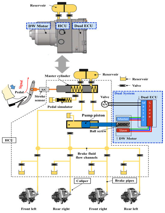
Figure 1.
Conceptual structure of the IEB system.
In the IEB system, the HCU consists of a master cylinder, pump piston, pedal simulator, and many valves. The master cylinder operates the brake with driver force in case of a system fault. In other cases, when the system operates normally without failure, the motor generates torque to apply force to the piston. The operating sequence of the IEB system is briefly described in the following. When the driver initiates a braking action by pressing the pedal, the dual ECU of the IEB system receives the input and sends a command to the motor. The DW motor’s rotational motion is then converted into the linear forward motion of the pump piston through a ball screw mechanism. The braking force generated by the DW motor, ball screw, and pump is transmitted to the vehicle caliper [19].
In a non-autonomous vehicle system, in the event of a motor failure, the driver can brake the vehicle by directly pressing the pedal. However, in the case of autonomous vehicle systems, the motor is responsible for all vehicle braking. For continuous operation of the motor for fail safety, a more robust DW motor is required.
A concept diagram of a DW three-phase motor is shown in Figure 2. First, the problem in the healthy mode is the simultaneous failure of both the master and the slave part, which may occur during unexpected overload operation. In the DW motor, the master and slave parts operate, but the current consumption is the same, so the coil temperature is also the same, as shown in Figure 3. Since the rate of increase of the coil temperature in the master part and the slave part is the same, the master part and the slave part may be simultaneously burned out during an unexpected overload operation. In this case, a DW motor does not have a redundancy function. Therefore, there is a need for a more robust motor design that can solve these problems.
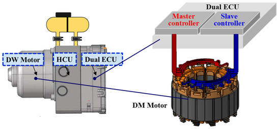
Figure 2.
Concept diagram of DW motor for IEB system.
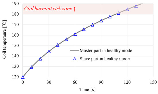
Figure 3.
Conventional DW motor operation in the healthy mode.
Second, the problem in the faulty mode is an overheating problem caused by a single operation of the master or slave part. In the faulty mode, only half of the motor works, so compared to the healthy mode, the motor current consumption is doubled, and the motor copper loss is quadrupled. Accordingly, when the operating state of the motor changes from the healthy mode to the faulty mode, the motor coil temperature increases rapidly, as shown in Figure 4.
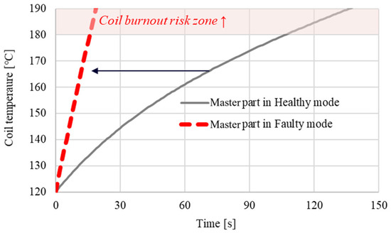
Figure 4.
Conventional DW motor operation in the faulty mode.
When a faulty mode occurs, it can be repaired after moving the vehicle to a safe place without driving anymore. However, if the vehicle encounters an unexpected situation on a high-traffic road, it may be necessary to drive it in the faulty mode for a longer period of time. If all these emergencies are considered, it is necessary to design the DW motor to be more robust so that no heat problem occurs, even during faulty operation. Thus, a more improved fault-tolerant design process is needed for DW permanent magnet (PM) motors considering the problems in both the healthy and faulty modes. Figure 5 illustrates the expected failure sequence when a fault occurs. The proposed ADW motor demonstrates that even under overload conditions, simultaneous burnout of the master and slave parts is prevented.
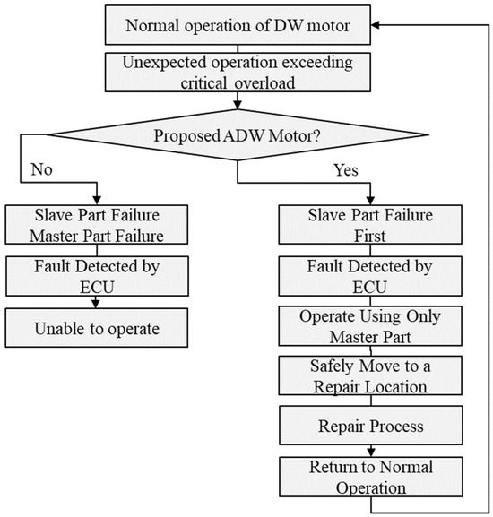
Figure 5.
Expected failure sequence of conventional DW motor and proposed ADW motor.
3. Proposed Optimal Design Process of Thermal Fault Tolerant ADW Motor
Figure 6 shows the proposed optimal design process of a thermal fault-tolerant ADW motor that simultaneously considers the problem of simultaneous failure of both the master and the slave parts in the healthy mode and overheating in the failure mode of a conventional DW motor. Since it is challenging to guarantee 100% protection against the worst-case scenario of overheating, the proposed ADW motor and its associated design process are designed to ensure that the motor can continue to operate even if the coil is damaged due to an overload condition.
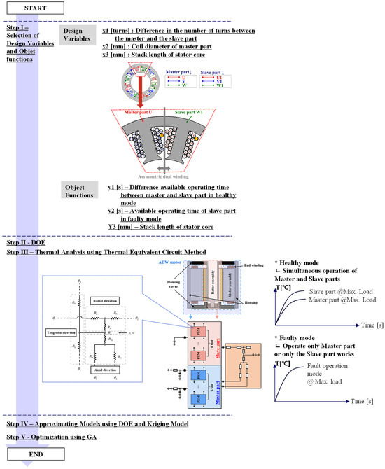
Figure 6.
Proposed design process of thermal fault-tolerant ADW motor in redundant IEB system.
It consists of a total of 5 steps. First, in step I, pertinent factors are chosen as design variables and object functions for a fault-tolerant ADW motor. The difference in the number of turns between the master and slave parts, along with the coil diameter of the master part and the stator core length, are identified as design variables. Subsequently, the objective functions are defined, including the stator core length, the temperature rise difference between the master and slave coils, and the available operating time in the faulty mode.
In step II, the design of experiment (DOE) method is used. In step III, a lumped-parameter thermal network (LPTN) with PSMs is used to perform a detailed thermal analysis of the ADW motor under both healthy and faulty operating modes. In step IV, a kriging model is employed to approximate the relationship between the selected design variables and the objective functions. Finally, in step V, an optimal design is conducted using a genetic algorithm (GA).
3.1. Selection of Design Variables and Object Functions (Step I)
In step I, design variables and objective functions are selected for the proposed thermal fault-tolerant ADW motor design as follows. In this study, to minimize the development cost, a dual-redundancy system was developed based on an existing three-phase winding motor. Existing motors are expressed as a base model. To use the stator core of the existing base model as it is, the proposed fault-tolerant ADW motor was designed by changing only the winding specifications of the master and the slave parts and the stack length of the stator without changing the slot dimension and the winding fill factor of the stator, as shown in Figure 7.
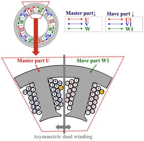
Figure 7.
Selection of design variables.
Design variables and objective functions are selected as follows:
where NM and NS are the numbers of turns in the master and slave parts, respectively. ΦM is the coil diameter of the master part, and SL is the stack length of the stator core. The remaining design variables required for the design of the ADW motor are obtained through the following expression:
where NB represents the number of turns per slot in the base model, ΦS denotes the winding diameter of the slave part, and DW and Ff are the slot area and winding fill factor, respectively. The objective functions are selected as follows:
where y1 is the time difference between TM and TS in the healthy mode, y2 is the TM in the faulty mode, and y3 represents the stack length of the stator core. TM and TS are the times when the coil temperatures in the master and slave parts reach 120 to 180 °C under maximum load conditions, respectively.
3.2. DOE (Step II)
In step II, design variables and objective functions are selected for the proposed thermal fault-tolerant ADW motor design as follows. In this study, to minimize the development cost, in step II, after the selection of the design variables and the targeted objective functions for the motor, approximate models between the design variables and objective functions are obtained using full factorial design (FFD) and the kriging model.
3.3. Comparison of Motor Stack Length Considering Overheat during Faulty Operation (Step III)
The LPTN incorporating PSMs is applied to perform an accurate thermal analysis of the DW motor under both healthy and faulty operational conditions [17]. The heat transfer coefficient values required for this analysis are obtained through optimization using a surrogate model based on the experiment results. The thermal equivalent circuit accounts for radial, tangential, and axial heat transfer, with the stator assembly divided according to the number of slots. Additionally, the thermal resistance calculation is based on a cylindrical component segmented to calculate resistances in all heat transfer directions. This allows for the estimation of the coil temperature increase during faulty operation when only a single winding of the DW motor is utilized. Figure 8 illustrates the concept of LPTN employing PSMs, and the equations are as follows:
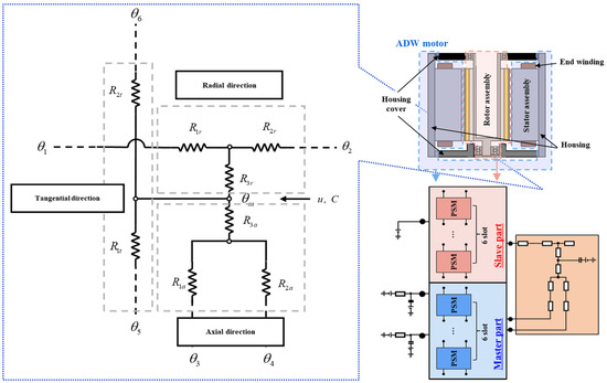
Figure 8.
The concept of LTPN employing PSMs of ADW motor.
The main thermal resistances necessary for configuring the thermal equivalent circuit are as follows:
where R1a and R2a denote the axial thermal resistances along the length of the cylinder, while R3a adjusts the axial temperature to balance maximum and average values. R1r and R2r represent the radial thermal resistances at the inner and outer diameters, with R3r ensuring temperature uniformity radially. R1t and R2t indicate tangential thermal resistances for the inner and outer diameters. corresponds to the angle of a slot, and C represents thermal capacitance.
In order to verify the effectiveness of the thermal analysis using the LPTN with PSMs, the measurement data of a previously developed conventional three-phase PM motor, which serves as the base model, are compared. Figure 9 illustrates the topology of the base model, which is an 8-pole 12-slot surface permanent magnet (SPM) motor. Detailed specifications are shown in Table 1.
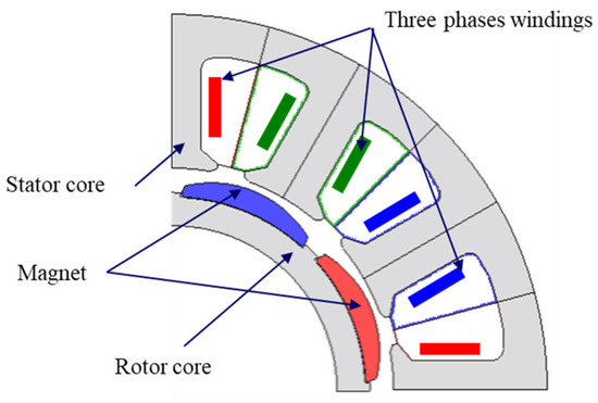
Figure 9.
Configuration of the base model.

Table 1.
Specifications of the base model.
The experimental setup for the thermal test is shown in Figure 10a. Figure 10b shows the manufactured base model and the winding connector. In order to measure the temperature of the coil wound in all slots, thermocouples are installed in all slots in the manufactured base model. These thermocouples were placed at the end turns of all slots, with the assumption that the temperature difference from the maximum hot spot inside the coil would be less than 10 degrees. Even within the same phase, temperature variations may occur depending on the placement of the thermocouples. For each condition, the thermocouple reading with the highest temperature rise rate was selected and recorded.
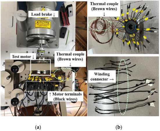
Figure 10.
Experimental setup for the thermal test of the base model. (a) Test bench setup; (b) test motor and winding connectors.
By utilizing winding connectors, it divides a DW motor into a master part and a slave part. After that, it is mounted on the test bench to measure the motor coil temperature for each load condition. Here, when the DW motor operates in the healthy mode, the current is applied to both the master part and the slave part. On the other hand, in the case of a faulty mode, the current is applied only to the master part or the slave part.
Figure 11 shows the coil temperature rise, comparing simulation results with experimental data, under a pressure load of 130 bar and an output torque of 3 Nm.
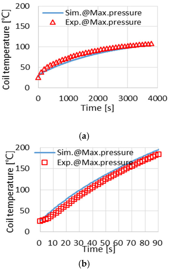
Figure 11.
Comparison of simulation and experimental results for the base model. (a) Healthy mode; (b) faulty mode.
The experimental results closely match the simulation data, confirming the effectiveness of the thermal analysis utilizing the LPTN with PSMs.
3.4. Approximation of the Models Using FFD and Kriging Modeling (Step IV)
In step IV, after selecting the design variables and target objective functions for the ADW motor, approximate models are developed to link these variables and objective functions using FFD and kriging modeling techniques. FFD explores all possible combinations of design variables to capture their interactions, while the kriging model provides an accurate interpolation for predicting unknown values based on known data points, which is particularly useful for non-linear systems [20]. This relationship can be presented as follows:
where represents the predicted value at a random variable , denotes the unknown mean of the Gaussian distribution, and ϵ(x) represents noise modeled as a normal distribution with a mean of zero and a variance of σ2.
The deviations in the stochastic Gaussian model are defined by the unknowns μ, σ2, and θj, and the optimization of likelihood is simplified using the natural logarithm as follows:
where L represents the likelihood function, which quantifies how well the statistical model fits the observed data; n refers to the number of data points or observations in the dataset; R is the correlation matrix of the model, indicating the degree of correlation between different data points; and y represents the observed data, which is compared against the predicted values from the model.
Taking the derivative of (20) and setting it to zero provides the maximum likelihood computations, yielding the most suitable estimates for the unknown variables μ and σ2 as follows:
The revised predicted value, at x, must consist of the available data and the identified correlated variables. Therefore, the prediction maximizes the probability of the sample data and the prediction is selected by considering the correlation variables. Then, the maximum of the quadratic function of is found by taking the partial derivative of (21) with respect to and setting it to zero. So, the standard kriging estimator is:
Using the established kriging model, approximate models are developed to link the design variables to the objective functions.
4. Optimal Design and Analysis of Thermal Fault Tolerant ADW Motor
The proposed design process for the thermal fault-tolerant ADW motor is implemented to ensure the proper operation of the IEB system, preventing overheating issues in the DW motor in the faulty mode. The design variables selected are shown in Table 2. Their ranges are chosen based on manufacturability considerations.

Table 2.
Range of design variables for FFD.
Table 3 shows the analysis results for the objective functions based on the FFD design combinations. Y1 represents the time difference between the master and the slave parts at which the coil temperature reaches 120 to 180 °C under maximum load conditions in the healthy mode. The temperature of 120 °C was selected based on the assumption that the engine room temperature, where the IEB system operates, could rise to a maximum of 120 °C. The motor has an air-cooled structure.

Table 3.
Simulation results for FFD.
Y2 is the time at which the coil temperature reaches 120 to 180 °C in the slave part under maximum load conditions in the faulty mode, and y3 represents the stack length of the stator core. While the continuous operating range under load conditions is approximately 20 bar, the analysis was conducted under intermittent operating conditions with a maximum pressure of 130 bar to account for thermal characteristics. Y3 represents the stack length, which is identical to the design variable x3. It is included as part of the objective function to minimize the stack length.
The objective functions are formulated and optimized using the kriging model and GA as follows:
Minimize: y3
Subject to: y1 > 60, y2 > 110
1 < x1 < 3, 1.48 < x2 <1.58, 40.5 < x3 <80.5
Figure 12 and Figure 13 show the process and outcomes of determining the optimal values for the design variables and objective functions.
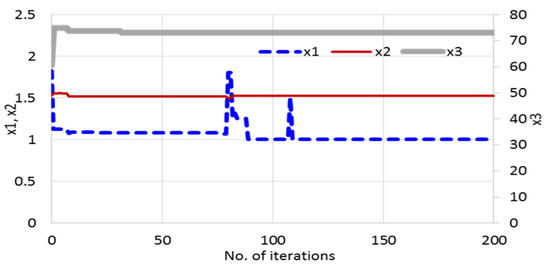
Figure 12.
Process of searching for optimal design variables via the GA.
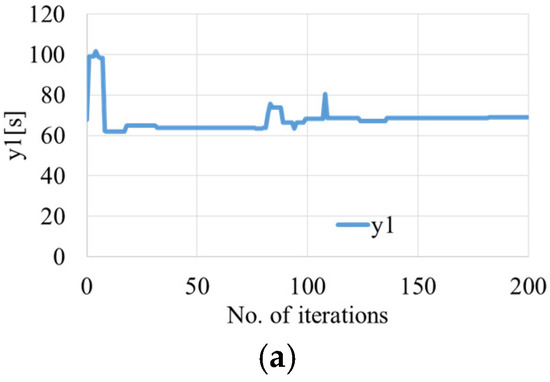
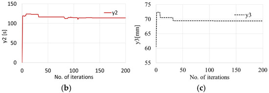
Figure 13.
Process of searching for object functions via the GA. (a) y1; (b) y2; (c)y3.
During the process, 200 iterations are performed to find the optimal value, taking approximately 3 min.
Table 4 and Table 5 list the design variables and objective function values for both the base motor and the optimized ADW motor, respectively. In the optimization model, since x1 is 1, the number of turns per slot of the master and slave parts can be obtained as 14.5 turns and 13.5 turns, respectively. Given the 0.5 turn difference for the 13.5 and 14.5 turn coils, the connections at the start and end of the coils can be made axially on different axis planes of the stator. In addition, the coil diameter of the slave part can be calculated as 1.424 mm by using the optimized x2 value of 1.53 mm and (7).

Table 4.
Optimization results for the design variables.

Table 5.
Comparison of objective function values between the base and optimized models.
Due to the difference in the number of turns between the master and the slave part of the optimization model, the current used in the master part with many turns is small. The currents used in master and slave parts are 26.78 A and 28.77 A in the healthy mode and 53.57 A and 57.53 A in the faulty mode, respectively. Thus, the loss in the master part is about 17.8% less than that in the slave part, so the coil temperature in the master part rises more slowly than in the slave part.
Figure 14 shows the actual winding configurations of the base model and the proposed ADW motor. Since the filling ratios of both models are the same, we can confirm that there are no issues with the winding, even if the winding diameter or number of turns differ. Figure 15 presents the temperature rise characteristics of the master part and slave part under full load conditions for the proposed optimized model, compared to the base model. Also, compared to the base model, the proposed model has some disadvantages in terms of increased cost and weight. However, considering the stability aspects of this model for autonomous vehicles, the significance of the proposed model becomes evident.
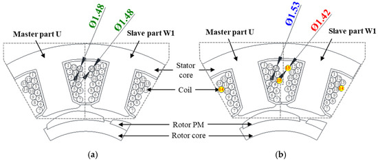
Figure 14.
Comparison of 2D drawings of the base model and the optimized model. (a) Base model; (b) Optimized model.

Figure 15.
Coil temperature rise estimation of optimized ADW motor under maximum load conditions. (a) Healthy model; (b) faulty mode.
5. Conclusions
In this paper, both a design process and a specific motor design were proposed for a thermal fault-tolerant asymmetric dual-winding (ADW) motor, aimed at solving the issues of simultaneous burnout in the healthy mode and overheating in the failure mode, which are both commonly observed in conventional dual-winding (DW) motors. The proposed design process includes optimizing the motor’s winding specifications and stack length, which effectively considers the prevention of simultaneous burnout and overheating during failure, as demonstrated through analysis. Although the optimization suggested that the stack length should ideally increase to more than twice its original length for optimal thermal management, practical considerations resulted in an actual increase of approximately 80%. This compromise ensures manufacturability and installation feasibility while still achieving significant improvements in thermal performance. This approach is anticipated to be applicable to a variety of redundant systems, such as steering or drive systems with DW motors and dual ECUs, in addition to IEB systems. These advances are critical to enhancing failure safety in autonomous vehicles and highlight the importance of the design process in improving system reliability and performance. Future research aims to delve deeper into control methodologies aimed at systematically minimizing thermal losses and energy consumption, thereby ensuring sustained efficiency improvements and operational reliability.
Author Contributions
Conceptualization, K.-Y.H. and S.-I.K.; methodology, K.-Y.H. and B.-K.S.; software, S.-Y.O.; validation, E.-K.P., K.-Y.H. and B.-K.S.; writing—original draft preparation, K.-Y.H.; writing—review and editing, B.-K.S. and S.-I.K.; supervision, S.-I.K. All authors have read and agreed to the published version of the manuscript.
Funding
This work was supported by the Technology Innovation Program (2021R1F1A1061806, Development of 600 kW–33,000 rpm ultra-high-speed motor and dynamometer control system) funded by the Ministry of Trade, Industry & Energy (MOTIE, Korea) and Regional Innovation Strategy (RIS) through the NRF funded by the Ministry of Education (2021RIS-004).
Data Availability Statement
Data is contained within the article.
Conflicts of Interest
Authors Seon-Yeol Oh and Baik-Kee Song were employed by the company Mando. The remaining authors declare that the research was conducted in the absence of any commercial or financial relationships that could be construed as a potential conflict of interest.
References
- Marzbani, H.; Khayyam, H.; To, C.N.; Quoc, D.V.; Jazar, R.N. Autonomous Vehicles: Autodriver Algorithm and Vehicle Dynamics. IEEE Trans. Veh. Technol. 2019, 68, 3201–3211. [Google Scholar] [CrossRef]
- Guo, J.; Kurup, U.; Shah, M. Is It Safe to Drive? An Overview of Factors, Metrics, and Datasets for Driveability Assessment in Autonomous Driving. IEEE Trans. Intell. Transp. Syst. 2020, 21, 3135–3151. [Google Scholar] [CrossRef]
- Vdovic, H.; Babic, J.; Podobnik, V. Automotive Software in Connected and Autonomous Electric Vehicles: A Review. IEEE Access 2019, 7, 166365–166379. [Google Scholar] [CrossRef]
- Lee, J.M.; Oh, K.S.; Oh, S.C.; Yoon, Y.M.; Kim, S.Y.; Song, T.J.; Yi, K.S. Emergency Pull-Over Algorithm for Level 4 Autonomous Vehicles Based on Model-Free Adaptive Feedback Control with Sensitivity and Learning Approaches. IEEE Access 2022, 10, 27014–27030. [Google Scholar] [CrossRef]
- J3016; Taxonomy and Definitions for Terms Related to Driving Automation Systems for On-Road Motor Vehicles. SAE International Standard: Warrendale, PA, USA, 2014.
- Yu, M.; Wang, D. Model-Based Health Monitoring for a Vehicle Steering System with Multiple Faults of Unknown Types. IEEE Trans. Ind. Electron. 2014, 61, 3574–3586. [Google Scholar]
- Li, X.; Xu, J.; Chen, Z.; Xu, S.; Liu, K. Real-Time Fault Diagnosis of Pulse Rectifier in Traction System Based on Structural Model. IEEE Trans. Transp. Electrif. 2022, 23, 2130–2143. [Google Scholar] [CrossRef]
- Zhang, L.; Wang, Z.; Ding, X.; Li, S.; Wang, Z. Fault-Tolerant Control for Intelligent Electrified Vehicles Against Front Wheel Steering Angle Sensor Faults During Trajectory Tracking. IEEE Access 2021, 9, 65174–65186. [Google Scholar] [CrossRef]
- Wang, Z.; Shao, J.; He, Z. Fault Tolerant Sensorless Control Strategy with Multi-States Switching Method for In-Wheel Electric Vehicle. IEEE Access 2021, 9, 61150–61158. [Google Scholar] [CrossRef]
- Bianchi, N.; Fornasiero, E.; Bolognani, S. Thermal Analysis of a Five-Phase Motor Under Faulty Operations. IEEE Trans. Ind. Appl. 2013, 49, 1531–1538. [Google Scholar] [CrossRef]
- Bermúdez, M.; Barrero, F.; Martin, C.; Perals, M. Performance Analysis of Direct Torque Controllers in Five-Phase Electrical Drives. Appl. Sci. 2021, 11, 11964. [Google Scholar] [CrossRef]
- Yepes, G.A.; Lopez, O.; Gonzalez-Prieto, I.; Duran, M.J.; Doval-Gandoy, J. A Comprehensive Survey on Fault Tolerance in Multiphase AC Drives, Part 1: General Overview Considering Multiple Fault Types. Machines 2022, 10, 208. [Google Scholar] [CrossRef]
- Jiang, X.; Huang, W.; Cao, R.; Hao, Z.; Jiang, W. Electric Drive System of Dual-Winding Fault-Tolerant Permanent-Magnet Motor for Aerospace Applications. IEEE Trans. Ind. Electron. 2015, 62, 7322–7330. [Google Scholar] [CrossRef]
- Noh, Y.; Kim, W.; Lee, J. The Optimal Current Ratio Control of Redundant Electric Drive Systems and Diagnostic Strategies for Disagreement. IEEE Access 2021, 9, 32115–32130. [Google Scholar] [CrossRef]
- Ha, J.R.; Kim, M.H.; Kim, S.W.; Yun, S.W.; Kim, K.S.; Kim, Y.S. A study on the characteristics of signal transmission in the electronic brake system for autonomous driving. In Proceedings of the 2023 International Symposium on Electromagnetic Compatibility—EMC Europe, Kraków, Poland, 4–8 September 2023. [Google Scholar]
- Hwang, K.Y.; Song, B.K.; Kwon, B.I. Asymmetric dual winding three-phase PMSM for fault tolerance of overheat in electric braking system of autonomous vehicle. IEEE Electr. Power Appl. 2019, 13, 1891–1898. [Google Scholar] [CrossRef]
- Song, B.K.; Chin, J.W.; Kim, D.M.; Hwang, K.Y.; Lim, M.S. Temperature Estimation Using Lumped-Parameter Thermal Network With Piecewise Stator-Housing Modules for Fault-Tolerant Brake Systems in Highly Automated Driving Vehicles. IEEE Trans. Intell. Transp. Syst. 2021, 22, 5819–5832. [Google Scholar] [CrossRef]
- Hwang, K.Y.; Kim, S.I.; Song, B.K. Single Winding Type Determination of Dual Winding Three-Phase Motor Considering Overheat Problem in Integrated Electric Braking System of Autonomous Vehicles. IEEE Trans. Transp. Electrif. 2023, 9, 656–666. [Google Scholar] [CrossRef]
- Lee, J.S.; Lee, H.S.; Nah, W.S. Minimizing the Number of X/Y Capacitors in an Autonomous Emergency Brake System Using the BPSO Algorithm. IEEE Trans. Power Electron. 2022, 37, 1630–1640. [Google Scholar] [CrossRef]
- Pal, A.; Zhu, L.; Wang, Y.; Zhu, G.G. Constrained Surrogate-Based Engine Calibration Using Lower Confidence Bound. IEEE/ASME Trans. Mechatron. 2021, 26, 3116–3127. [Google Scholar] [CrossRef]
Disclaimer/Publisher’s Note: The statements, opinions and data contained in all publications are solely those of the individual author(s) and contributor(s) and not of MDPI and/or the editor(s). MDPI and/or the editor(s) disclaim responsibility for any injury to people or property resulting from any ideas, methods, instructions or products referred to in the content. |
© 2024 by the authors. Licensee MDPI, Basel, Switzerland. This article is an open access article distributed under the terms and conditions of the Creative Commons Attribution (CC BY) license (https://creativecommons.org/licenses/by/4.0/).