Article

Analysis of Friction and Wear Properties of Friction Ring Materials for Friction Rings under Mixed Lubrication

1
School of Electrical Engineering, Xinjiang University, Urumqi 830047, China
2
School of Mechanical Engineering, Xinjiang University, Urumqi 830047, China
*
Author to whom correspondence should be addressed.
Machines 2024, 12(10), 680; https://doi.org/10.3390/machines12100680
Submission received: 19 August 2024 / Revised: 18 September 2024 / Accepted: 26 September 2024 / Published: 27 September 2024
(This article belongs to the Section Friction and Tribology)

Abstract

:
Aiming at the problem of mechanical seal failure due to serious wear and tear in operation, the numerical model of the thermal–solid coupling wear of the seal ring is established by taking the friction sub-material as the research object, and the hardness, wear coefficient, and friction coefficient of different soft-ring materials are obtained by a test to verify the accuracy of the numerical model of wear. Additionally, the temperature field and deformation field of the seal ring of different materials are calculated, and the effects of the material parameters, such as elasticity modulus and thermal conductivity, on the temperature, relative deformation, and axial deformation trend are reported. The wear relation of the mechanical seal was optimized, and the correction coefficients of several materials were calculated. The results show the following: the main wear of the seal ring is due to adhesive wear leading to particle shedding and extrusion, adhesive wear causes material transfer, which alters the composition of the worn surface.in turn leading to cratering, which also causes the wear of the seal ring; the friction performance is better when the soft-ring material is graphite (C); the temperature, as well as the deformation, is smaller when the soft-ring material is silicon carbide (SIC); the correction coefficients for the life of SIC are calculated to be 0.23, for C, to be 0.14, and for stainless steel (Ss), to be 0.31, and the corrected equations can more accurately predict the corresponding material. The corrected equation can more accurately predict the service life of the corresponding material.

1. Introduction

Contact mechanical seals are widely used in aviation, shipping, chemical, and other industries because of their small leakage, simple structure, and low cost, but their wear and tear is more serious compared to non-contact mechanical seals [1]. Failure of the friction ring end face is a major cause of pump failure. Failure can lead to high end-face temperatures and deformation, which, in turn, can lead to the wear and rupture of the seal end face, which brings great challenges to the safety performance and service life of the sealing device, and, at the same time, it will also cause pollution of the environment, as well as economic losses, so contact mechanical seal friction mechanism research is very necessary [2].
In analyses of plant slurry pumps in recent years, in 1500 failure cases, the plants’ seal-ring service life of 1000–1500 h, GB/T33509-2017, stipulates a service life of not less than 4000 h [3]. Additionally, according to mechanical-seal life predictions [4], which calculate the plant seal-ring life to be of 384 h, in actuality, there is a large deviation; with the selection of suitable sealing materials, the wear relation has been amended, and, now, realizing a more accurate prediction life of the purposed item is the primary problem.
For the selection and improvement of sealing-ring materials, scholars at home and abroad have carried out a large number of experimental studies. Wei Wenhao [5] and others analyzed the effect of material parameters such as the modulus of elasticity, the coefficient of thermal expansion, and other material parameters on the frictional wear and leakage of the sealing ring; finally, they selected the optimal dynamic-ring material. Juying Zhao et al. [6] investigated the friction and wear characteristics of graphite impregnated with inorganic salts on stainless steel in a ring–ring friction vice and concluded that the coefficient of the friction of graphite decreases with the increase in load; additionally, the wear rate increases, and the taper angle increases when the load increases. Qiu Wei and others [7] studied slurry pumps in the engineering of theoretical wear and found that the actual wear is not consistent with the problem; they optimized the mechanical seal wear relation and improved the mechanical seal end-face structure. Goikar [8] studied the friction and wear characteristics of antimony-impregnated carbon–graphite materials used in steam rotary joints and measured the wear loss, friction torque, and surface temperature of sealing surfaces. Zhao et al. [9] investigated the friction performance of silicon carbide, including graphite-added silicon carbide. Under water and lubricated conditions were studied by using a Falex-1506 tribotester(Falex Corporation, Illinois, USA), and different working parameters suggest that graphite-added silicon carbide shows better frictional performance. Cui et al. [10] developed new self-lubricating bronze matrix composites for seals and explored the tribological mechanisms of anti-wear hydraulic fluids using a ball–disc friction tester. Zhao [11] studied the effect of the friction coefficient and wear rate with increasing the PV (product of pressure and velocity) of different high-speed turbopump mechanical seal gasket materials under dry friction, as well as the lubricated friction, and compared the friction and wear behaviors of several materials. In conclusion, previous studies have shown that investigating the suitability of materials [12,13] for sealing subassemblies and improving the surface properties of materials [14,15] can significantly improve the friction and wear performance of seals under extreme conditions, and these results have also been used for selecting materials, treating surfaces, and being able to improve the tribological performance of mechanical seals, as well as even monitoring the tribological behavior of mechanical seals.
However, most of these studies are based on ideal environments, are experimental or theoretical in nature, and lack an exploration of the engineering field. This paper synthesizes the above deficiencies and selects several materials used for mechanical seal friction vices, including stainless steel (Ss), graphite (C), and silicon carbide (SIC). It compares the thermal stability as well as resistance to the deformation of several materials, combining with the economy of the actual production and selecting the appropriate sealing ring material and wear relation correction to improve the applicability. The results of the study have certain theoretical significance in guiding the study of the friction mechanism of contact mechanical seals and provide a reference for the material application and design optimization of mechanical seals in industrial applications.

2. Modeling and Numerical Analysis

2.1. Geometric Models

The friction pair sealing ring was modeled, and the dimensions and 3D model are shown in Table 1 and Figure 1.

2.2. Numerical Analysis

The thermal deformation analysis of the sealing ring is carried out separately for soft rings of several materials. It requires the calculation of the convective heat transfer coefficient and the heat flow density at the end face.

2.2.1. Basic Assumptions for Thermal Deformation Analysis

The following assumptions are made for ease of calculation:
  • Neglecting the heat carried away by the leakage, the heat generated by friction is regarded as the heat source, and all of it is transferred between the sealing rings.
  • The edge of the seal ring in contact with the air side is regarded as adiabatic, and convective heat transfer is generated with the flushing liquid.
  • The properties of the sealing-ring material do not change with temperature, and the coefficient of friction remains unchanged.
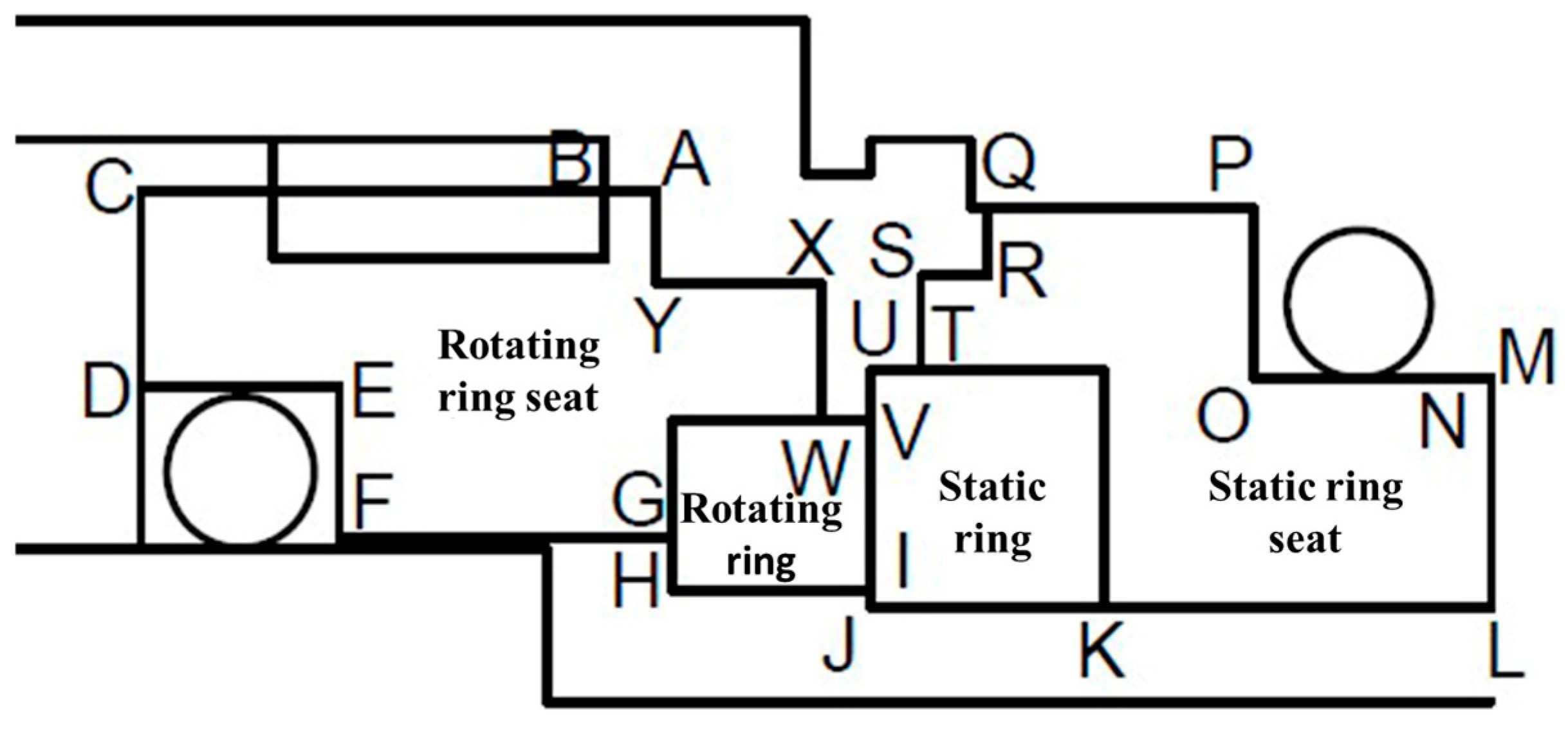
The boundary conditions for the simulation analysis of the friction pair seal ring are shown in Figure 2. Table 2 presents the boundary conditions for the mechanical seal force, while Table 3 presents the thermal boundary conditions for the mechanical seal.

2.2.2. Calculation of Thermodynamic Parameters

Due to the special operating conditions of the slurry pump, it is difficult for the friction pair to form a complete liquid film, so, in this paper, a computational alternative method is used, which first calculates the forces exerted by the flushing fluid on the dynamic and static rings of the seal, as well as the convective heat transfer changes caused by the flushing, and then converts these effects into boundary conditions applied in the FEM.
The frictional heat flow density between the dynamic and static rings of the friction sub-seal ring is calculated by Equation (1) [4].
q = f w V p c
In Equation (1), q is the heat flow density; fw is the mixing friction coefficient, measured experimentally; V is the average linear velocity of the end face of the moving ring; and pc is the end-face-specific pressure. Spring pressure and end-face pressure are the two most important parameters of mechanical seals. In engineering applications, to determine the applicability of mechanical seals, the first step is to determine the size of the spring pressure, which is too small to lead to insufficient thrust and mechanical seal leakage and too large to lead to the pressure being too tight. Mechanical seals wear rapidly.
For mechanical seals with end-face linear velocity less than 10 m/s, the spring-specific pressure is 0.15–0.6 MPa, and, for pump mechanical seals, the end-face-specific pressure is 0.2–0.7 MPa [4].
p c = p s p + p s B K s t
p s p = F s p A f
where psp is the spring-specific pressure; ps is the flushing fluid pressure of 1.6 MPa; B is the equilibrium ratio; and Kst is the film-pressure coefficient. The friction vice seal-ring end face is set between the average pressure of the liquid film and the ratio of the pressure of the flushing fluid. For the contact mechanical seal and in the mixing friction, and the boundary friction under the seal end face, the liquid film pressure can be used to approximate the calculation of this value. Fsp is the spring load, and Af is the area of the sealing surface in mm2. After calculation, the spring-specific pressure is 0.20 MPa, and the end-face-specific pressure is 0.59 MPa, which is in accordance with the empirical values, proving that the calculated parameters are reasonable and can be used for subsequent calculations [16].
After the heat flow density is obtained, the heat distribution ratio of the dynamic and static rings shall be calculated by Equation (4) [2]:
q r q = q r q r + q s = 1 1 + h r λ s h s λ r
where qs is the heat allocated to the end face of the static ring; qr is the heat allocated to the end face of the rotating ring; hr is the axial thickness of the rotating ring; hs is the axial thickness of the static ring; λr is the thermal conductivity of the rotating ring; and λs is the coefficient of thermal conductivity of the static ring. Combined with the data from Table 4, the final dynamic and static-ring heat flux densities are shown in Table 5 through calculation.
Convection heat dissipation coefficient: thermal convection refers to the process of heat transfer due to the fluid macroscopic and caused by the fluid between the parts of the relative occurrence of cold and hot fluids mixed with each other as a result of the heat transfer process.
q = α T w T f A
where α is the convective heat transfer coefficient; Tw and Tf are the wall temperature and liquid temperature; and A is the area through which the heat passes. This study selects the horizontal rotating cylindrical forced single-phase flow heat transfer relation in the annular finite space to calculate the heat transfer coefficient [17].
N u = 0.195 R e 0.5 P r 0.25
α = λ l N u Δ R
R e = ω Δ R 2 / v l R / Δ R
P r = μ C p / λ l
where Nu is the Nusselt number; Re is the Reynolds number, calculated from Equation (9); Pr is the Prandtl number; μ is the dynamic viscosity; ω is the relative rotational angular velocity; and ΔR is the clearance between the two cylinders, which, for the outer, is the distance between the sealing cavity and the outer diameter of the sealing ring and, for the inner, is the distance between the outer diameter of the shaft sleeve and the inner diameter of the sealing ring. R is the inner cylindrical radius, the outer-sealing-ring outer diameter, and the inner sleeve outer diameter. vl is the kinematic viscosity of the medium; λl is the thermal conductivity of the medium; and Cp is the specific heat capacity of the medium.
The convective heat transfer coefficients for several materials were calculated and are shown in Table 6. The solid section contact heat transfer coefficient between thermally conductive stainless steel and stainless steel was 6000 W·(m2·°C)−1 [18].

2.3. Archard Wear Model

Slurry pump mechanical seal wear and tear brought about by abrasive wear from mainly pumping media (refined phosphate slurry), as well as mechanical seal operation generated by adhesive wear, is here studied. In this paper, we focus on the study of adhesive wear on the friction vice seal-ring end-face role. Adhesive wear is when two solid surfaces come into contact and undergo relative motion, material transfer and adhesion occur due to the micro-roughness of the surfaces. As sliding continues, there will be material detachment, transfer, and re-adhesion between the surfaces, leading to wear and surface damage. There are many relations for calculating this type of wear; this paper adopts the most classic Archard wear relation. Archard in 1953 proposed the theory of adhesive wear public [19], see Equation (10); Gu Yongquan corrected the relation to derive the mechanical seal wear relation, see relation (11), and pointed out that the mechanical seal end-face wear of 3 mm is regarded as a failure. The life expectancy of the mechanical seal is shown in Equation (12):
v = K w W x h H
γ = K w p c V H
t = 3000 γ
where v is the amount of wear; W is the load; and xh is the sliding distance; γ is the depth of mechanical seal wear; and Kw is the dimensionless wear coefficient, which is the probability of material debris transfer or the probability of abrasive particles generated by a defined shape of micro-convex body. Kw/H is the wear rate. In order to simplify the calculation, it is assumed that the friction ring wear is in the stable wear stage and the friction and wear coefficients are unchanged. H is the Brinell hardness of the sealing ring, and t is the life of the mechanical seal. The wear coefficients and hardness need to be measured through the test.

3. Wear Test

3.1. Test Material

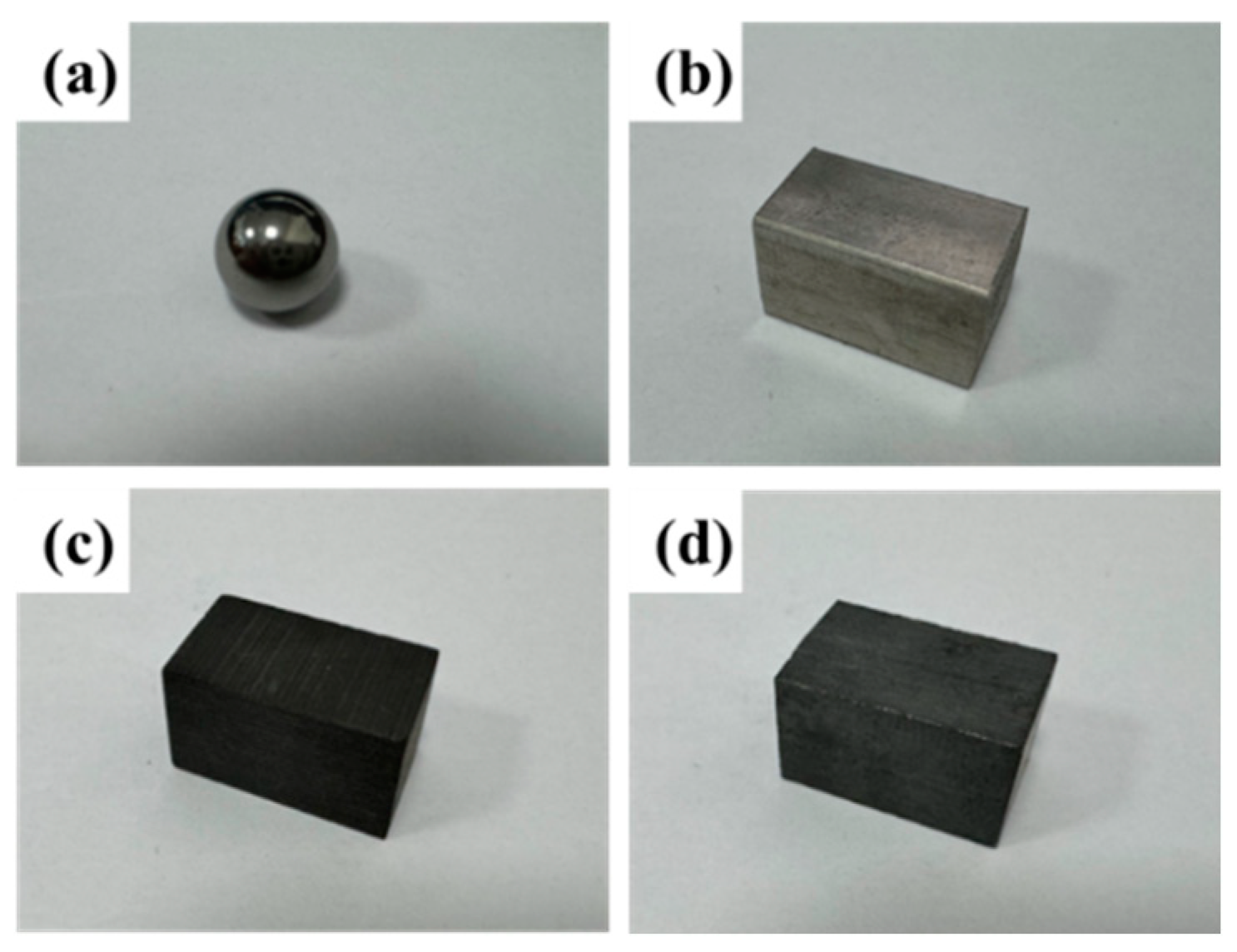
A higher hardness WC-Co alloy (YG8) was selected as the sphere with a diameter of 9 mm, and the three materials used for the paired sealing sub are as follows: Ss, C, and SIC, all of which have dimensions of 10 mm × 10 mm × 17 mm. All the samples are shown in Figure 3, and the attribute parameters of the sample materials are listed in Table 7.
The MP-2B grinding and polishing machine was used to grind and polish the end face of the friction vice of the sample to 0.4 roughness to ensure the roughness and parallelism of their surfaces, and, in order to reduce the abrasive debris and impurities, etc., on their polished surfaces, the specimens were ultrasonically cleaned with an ultrasonic cleaner (KQ-50DB, Foshan, China). The surface roughness before the performance treatment was measured by an interference microscope (Wyko NT1100, Veeco, Plainview, NY, USA). The hardness was measured by a digital Rockwell hardness tester (HRS-150, SCTMC, Shanghai, China), and the surface morphology was captured by three-dimensional visualization using a super-depth field microscope (VHX-6000, Keyence, Osaka, Japan).
In order to study the effect of different materials on the seal end face, different static-ring materials and dynamic-ring materials were combined and paired, as shown in Table 8.

3.2. Friction Wear Test

The equipment in this paper is a multifunctional friction rubbing tester (MFT-5000, RTEC, USA), which utilizes a high-frequency reciprocating module to perform the tests. During the experiment, the pin samples are YG8 pins (hard-ring seal material), which are clamped by a fixture attached to a multidirectional transducer. The slider sample is the test material, fixed to the base and driven by a stepper motor for reciprocating motion. The sphere sample remains stationary during the test, as shown in Figure 4. The test parameters were set in the control panel or software interface, adjusting the load of 10 N, sliding distance of 15 mm, and test time of 1 h, and each group of tests was conducted three times to obtain the coefficient of friction. Before and after the experiment, it was necessary to ultrasonically clean the specimen to ensure the purity of the specimen surface to remove surface impurities and contaminants. After cleaning, the specimens were dried and weighed using an analytical balance to determine the wear mass and thus calculate the wear coefficient.

4. Results and Discussion

4.1. Simulation Analysis Results

4.1.1. Temperature Field Analysis

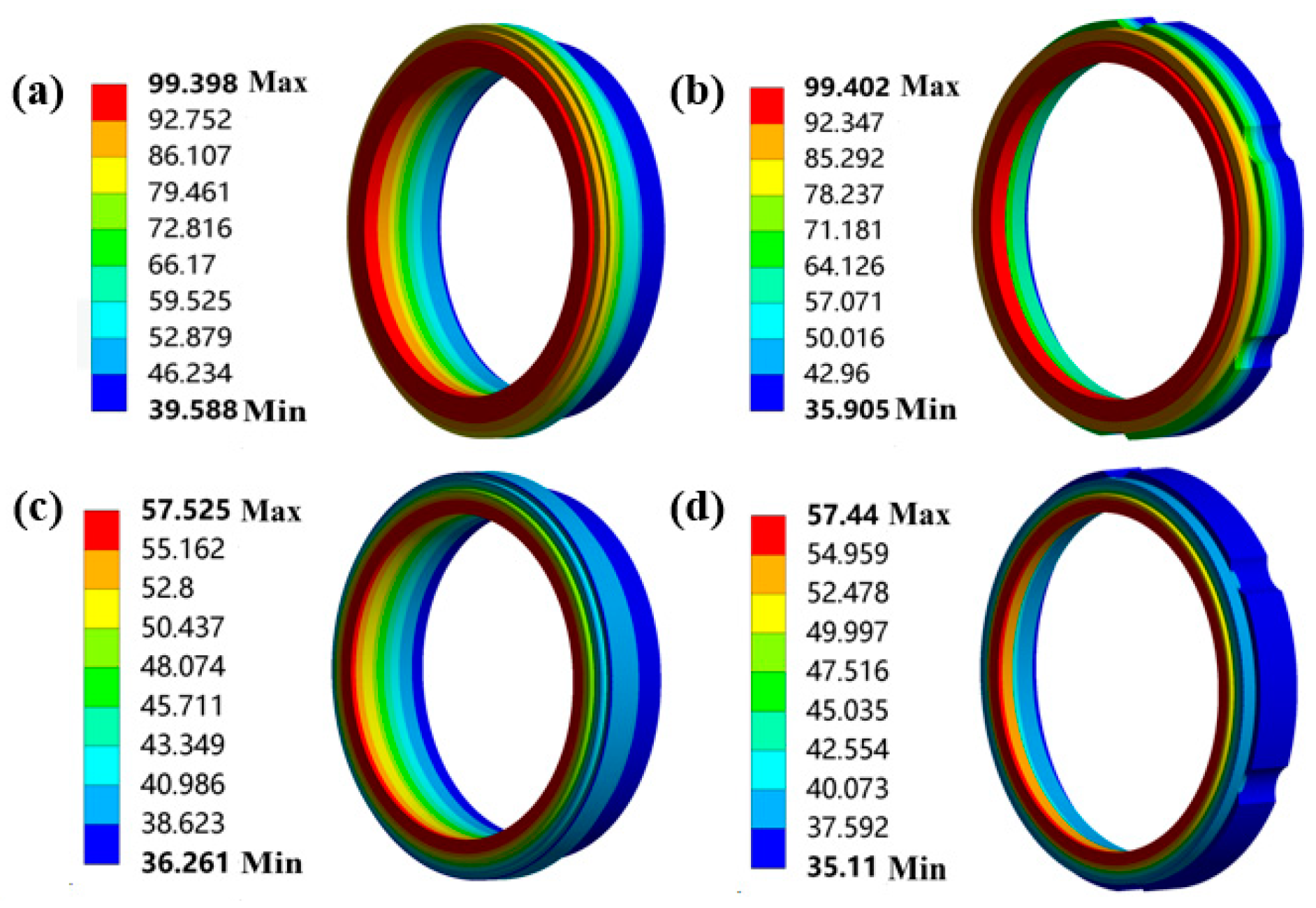
Take the SIC material sealing ring as an example to analyze. The end-face temperature is shown in Figure 5. Due to the difference of the soft-ring material, resulting in the difference of the degree of the internal and external diffusion of heat, it can be observed from the temperature distribution of the sealing-ring end face that the highest temperature of the sealing-ring surface will be gradually shifted from the mid-diameter to the direction of the inner diameter. The relative rotation of the dynamic and static-ring end faces produces frictional heat, and the heat cannot be dissipated in time, resulting in an end-face temperature rise. When there is flushing, the steady-state temperature of the sealing end face does not reach the boiling point of the cooling water, and only a very small part of the end face exists in the vapor caused by the high temperature of the flash point, so that the point is in the gas–liquid two-phase flow sealing state; therefore, the operation is more stable. Additionally, the ring-seat temperature distribution has a significant downward trend, and the outer diameter part of the flushing produced convective heat transfer, reducing the temperature.
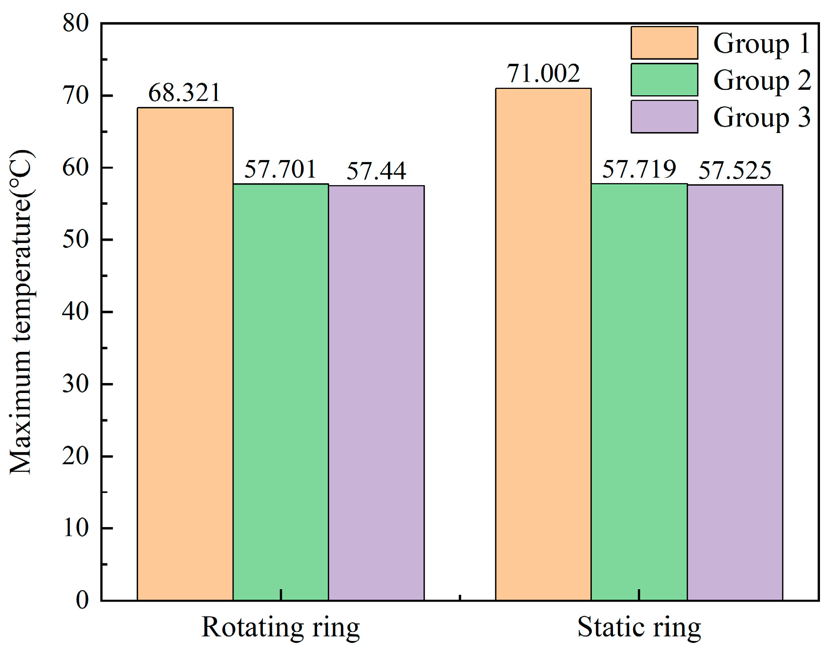
A comparison of the maximum temperature of different soft material sealing rings is shown in Figure 6. Ss is a chromium-containing alloy with low thermal conductivity and slow heat conduction, which usually produces a high coefficient of friction and frictional heat under friction conditions. C has good thermal conductivity; its coefficient of thermal conductivity is located in between. With good self-lubrication and thermal conductivity, the abrasion can reduce friction and wear so as to reduce the generation of heat. SIC has the largest thermal conductivity among several materials, as well as excellent wear resistance and high-temperature stability, which can effectively resist frictional wear and can quickly conduct the heat generated by friction, lower the temperature gradient, reduce heat accumulation, and help to prevent the friction interface from being too hot.

4.1.2. Thermal Deformation Analysis

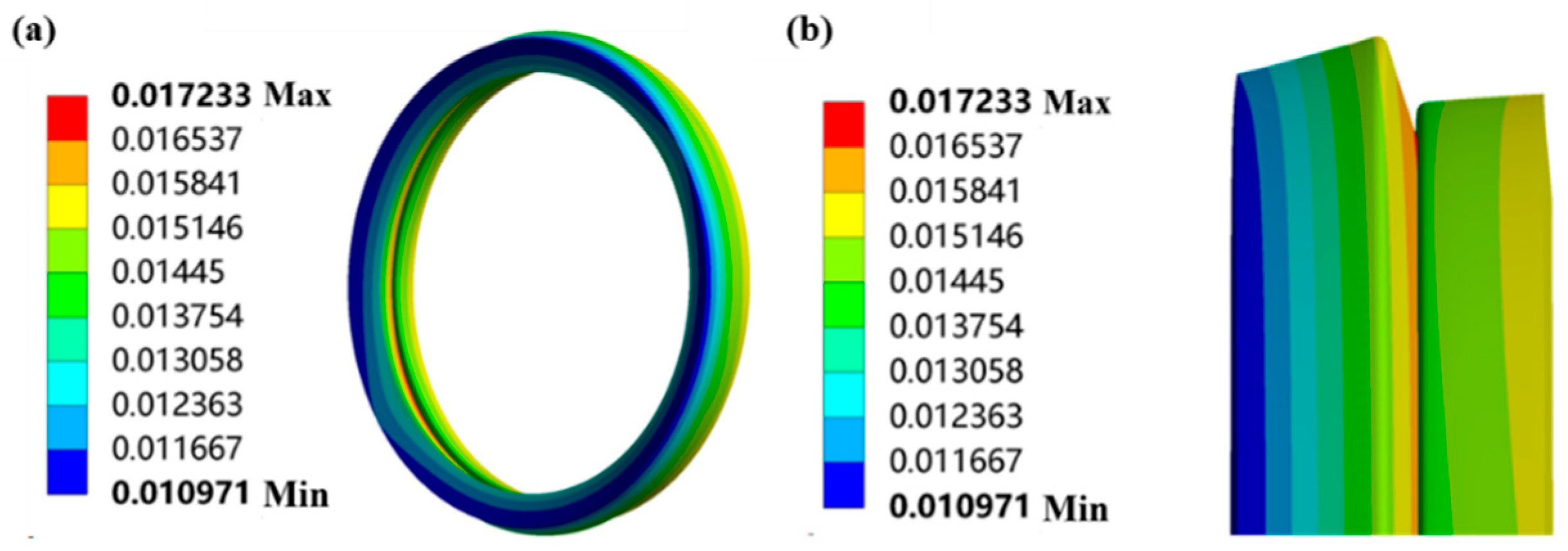
Take the SIC material sealing ring as an example. As can be seen from Figure 7, the inner diameter deformation is larger. The reason is that the outer diameter is subject to the cooling water flushing; what’s more, the inner diameter is assumed to be adiabatic, the heat cannot be dispersed, the temperature is higher, and the material expansion is serious, so the inner diameter has a greater deformation. After thermal deformation, the friction from the parallel surface to the convergent surface results in a smaller contact area of the sealing end face. The traditional theory is that the convergence surface will cause the solid contact pressure to increase and the sealing surface to experience rapid wear, but the deformation compared to the friction vice seal-ring size is very small, and the contact pressure increase is small.
Figure 8 shows that after the deformation of the friction ring, the gap between the dynamic ring and the static ring occurs. Take the SIC seal ring for example; a 0.45 μm gap occurs at the inner diameter of the seal ring, and, from the data, it can be seen that the seal ring is in a parallel state with a gap of 0.34 μm. So, after the thermal deformation of the seal ring, the seal-ring inner diameter gap increases to 0.79 μm. At the same time, the seal ring is in the water lubrication condition, and the end-face gap increases will result in more flushing media. Again, at the same time, the sealing ring is in a water lubrication condition; the increase in the end-face gap will cause more flushing media to enter the end face to increase the thickness of the liquid film and reduce the friction and wear. From a microscopic point of view, the decrease in the number of micro-convex body contacts on the end face due to the increased end-face clearance and the decrease in the contact area of the rough peaks also lead to a decrease in wear.
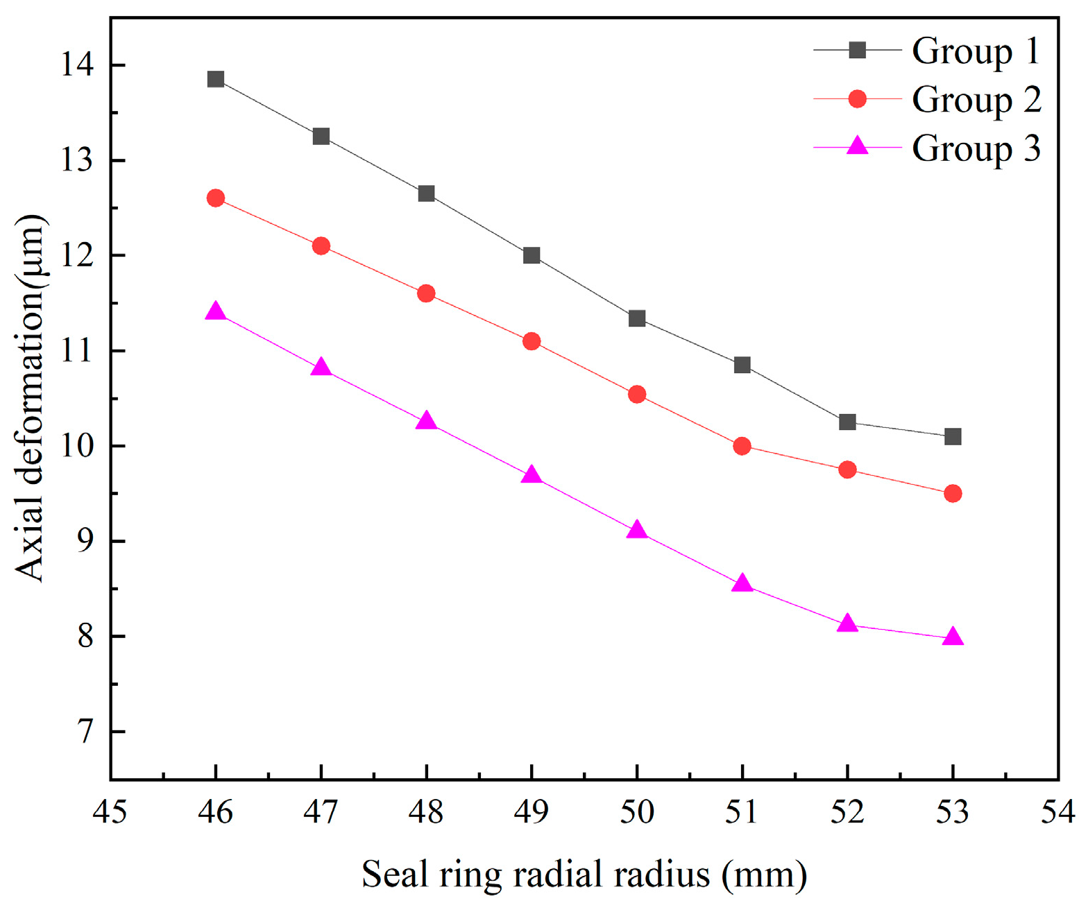
Figure 9 shows the axial deformation of the seal rings of different materials. It can be seen that the deformation of Ss is usually larger at high temperatures due to the high coefficient of linear expansion. Additionally, Ss has a relatively low strength and hardness and is prone to plastic deformation. C has high flexibility and self-lubrication, which leads to a relatively large deformation of graphite when subjected to axial force. The coefficient of the thermal expansion of SIC is lower than the rest of the material, with high hardness, high temperature resistance, and small thermal deformation, which can maintain good dimensional stability.
The inlaid mechanical seal formed due to the ring and the ring-seat material of the linear expansion coefficient of deviation; therefore, in high temperature conditions, the ring will be dropped, which is one of the important reasons for the failure of such mechanical seals. In addition to temperature, the ring seat and ring deformation difference is too large, which will also lead to a dropped ring. Once the ring and the relative deformation of the ring seat are too large, they will also drop the ring. In this paper, the relative deformation of the friction ring of different materials can be collected in the finite element model, and the relative deformation is obtained by subtracting the radial deformation of the seal ring from the radial deformation of the ring seat. The specific data are shown in Figure 10. As can be seen from the figure, because the overall temperature of the friction sub-seal ring is not high under the steady-state temperature field, the flushing liquid and pumping medium will inhibit the deformation of the dynamic and static rings. Additionally, the relative deformation of several materials is small, and there will be no ring dropping.

4.2. Test Results

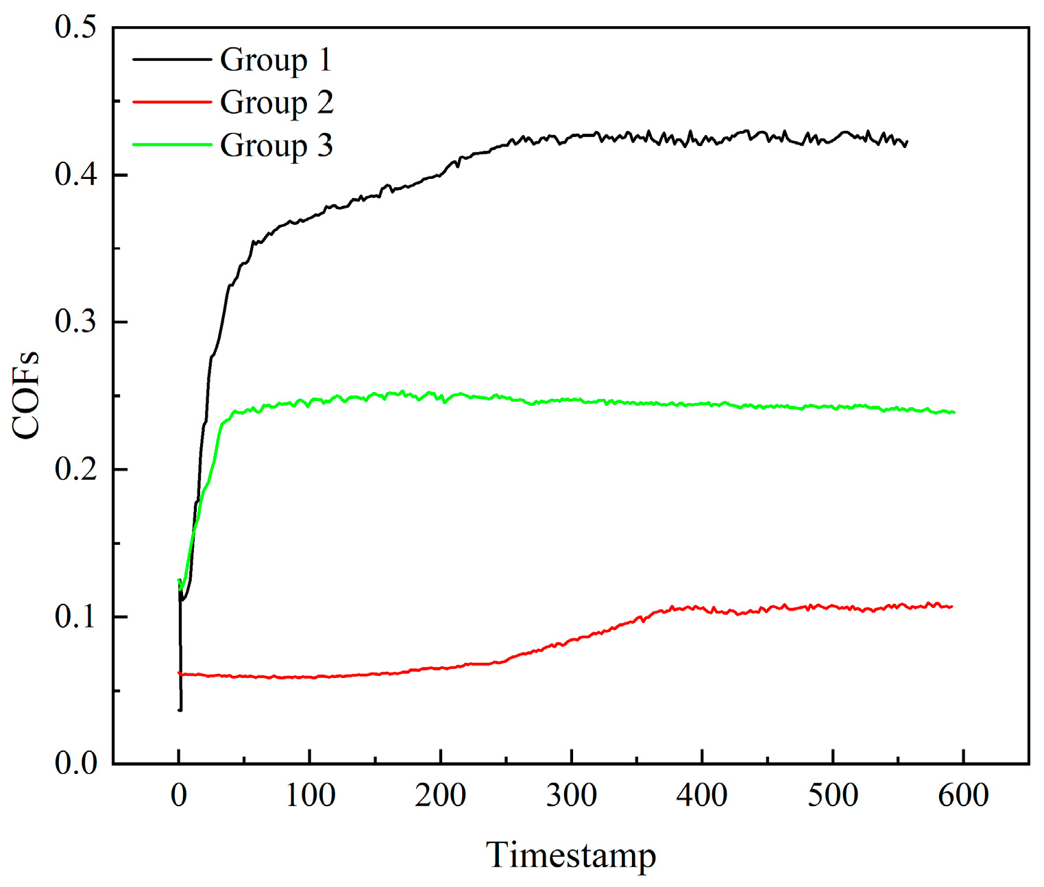
Figure 11 shows the friction coefficient curves obtained from wear experiments performed on several material specimens. As can be seen from the figure, in the initial period of the experiment for the initial break-in stage, due to the lack of a stable transfer film, the friction coefficient shows a complex fluctuation state. After reaching a certain stage, the friction coefficient becomes stable, and, after taking the average value, the friction coefficient of Ss is 0.42, C is 0.096, and SIC is 0.24. Substituting into Equations (11) and (12) to calculate the Kw, the Ss is 1.5 × 10⁻⁵, the C is 3 × 10⁻⁶, and SIC is 2 × 10⁻⁵.
Figure 12a shows the surface topography of the SIC test specimen, Figure 12b is the image of the 3D visualization acquisition demonstration of the super-field-of-view microscope mirror. The sliding wear process usually involves three kinds of main wear mechanism: adhesion, abrasion, and surface fatigue [20], which are associated with specific wear manifestations and can be defined by them. However, the sliding process still depends on the structure of the friction system and the nature of the materials involved, leading to changes in the topology, chemical composition, and microstructure of the surfaces, as well as the interfaces and the surrounding medium, which results in different sub-mechanisms for each of the main mechanisms [21]. In order to investigate the wear mechanism of the seal ring, the wear surface of the wear specimen was observed morphologically using SEM electron microscopy (505i, FEI, Hillsboro, OR, USA). As can be seen from Figure 12c, the wear area is distributed with a large number of particles. This, therefore, indicates that the primary wear mechanism is adhesive wear, and, from these pits, it can be demonstrated that its sub-mechanism is an indentation. Figure 13b shows the EDS (505i, FEI, USA) analysis of the YG6 surface, whereas Figure 13c shows the elemental energy spectrum of the graphite surface. The main component of the graphite surface is element C, with a small amount of element O. The presence of element W is detected on the graphite surface, as shown in Figure 13a, indicating that material transfer occurred on the hard-ring surface due to adhesive wear. Adhesive wear results in the transfer of material changing the composition of the wear surface. It also affects the coefficient of friction and the wear rate between the friction partners.

4.3. Correction to the Wear Relation

Although the finite element simulation can accurately predict the expected service life of the friction sub-seal ring, due to the lack of time and technology at the work site, it mostly uses the wear relation to roughly estimate the service life so as to plan the production. Therefore, in order to make the wear relation more accurate and ensure smooth production, the effect of thermal deformation on the wear depth is introduced, and a correction coefficient, n, is added to Equation (12); see Equation (14), where n is the ratio of the theoretical wear depth to the simulated wear depth under thermal deformation. There are many factors affecting wear and tear that take into account the different nature of the materials, each of which has a separate correction factor.
Some scholars have studied the effect of temperature on wear. Lee and Joub [22] modified the Archard wear equation. They considered the hardness H and wear coefficient K at high temperatures as a function of temperature T, see Equation (13). However, the modified equation is only applicable to the prediction of the wear of mold steel in the environment above 400 °C. Additionally, the mechanical seal in this paper is In a lubricated state, and the temperature is much lower than 400 °C. Therefore, assuming that K and H are fixed values, the wear results can be made more accurate by adding a correction factor, n, which represents thermal deformation; see Equation (14).
From the experimental data and simulation data, in relation to calculating the SIC correction coefficient of 0.23, C is 0.14, and Ss is 0.31. By comparing the friction and wear of the seals under different loads and speeds, we obtained similar correction factors from different experimental studies of the same material. Therefore, it is considered that the correction factor is related to the material properties, and the results for each material are not applicable to other materials. Calculating the coefficients for more materials allows for a more accurate and convenient prediction of the service life of these materials when they are used.
γ = K T P V r H T
γ = n K w p c V H

5. Conclusions

This paper establishes the slurry-pump mechanical-seal performance analysis geometric model through thermal coupling analysis and calculation. It analyzes the temperature field and deformation field of different dynamic and static-ring materials and the influence of different soft-ring materials on the sealing performance of the seal ring. Additionally, through tests, it measures the hardness of the material, the coefficient of friction, and the coefficient of wear and tear, and it corrects the wear relation.
  • The friction performance is better when the soft-ring material is C. The temperature, as well as the deformation, is better when the soft-ring material is SIC, and the overall performance is better.
  • Through SEM morphology observation of the test specimens, the main wear of the dynamic and static rings is due to adhesive wear leading to particle shedding, which in turn leads to cratering by extrusion, resulting in the wear of the sealing ring.
  • The correction coefficients for several materials were calculated, and the correction coefficients were obtained to be 0.23 for SIC, 0.14 for C, and 0.31 for Ss, which can more accurately predict the service life of mechanical seal gaskets.

Author Contributions

Conceptualization, R.Y. and T.L.; software, T.L.; validation, T.L., R.Y. and M.A.; investigation, T.L.; resources, M.A.; data curation, T.L.; writing—original draft preparation, T.L.; writing—review and editing, T.L.; project administration, M.A.; funding acquisition, M.A. All authors have read and agreed to the published version of the manuscript.

Funding

The author(s) disclosed a receipt of the following financial support for the research, authorship, and/or publication of this article. This work was supported by the Natural Science Foundation of Xinjiang Uygur Autonomous Region (grant number: 2021D01C045).

Data Availability Statement

The data presented in this study are available upon request from the corresponding author.

Conflicts of Interest

The author(s) declared no potential conflicts of interest with respect to the research, authorship, and/or publication of this article.

References

  1. Bi, H.-C.; Hao, M.M.; Ren, B.-J.; Sun, X.-H.; Li, Y.-F.; Li, T.-Z.; Liu, F.-Y.; Li, X.-Y. Friction E-volution of contact Mechanical seals under Mixed lubrication. Tribology 2023, 43, 1241–1253. [Google Scholar]
  2. Yu, M. Thermal and Structural Coupling deformation Analysis and parameter Optimization of sealing ring with outer circular groove. Lubr. Seal. 2020, 45, 66–71. [Google Scholar]
  3. GB/T 33509-2017; General Specification for Mechanical Seals. General Administration of Quality Supervision, Inspection and Quarantine of the People’s Republic of China, Standardization Administration of the People’s Republic of China. China Standard Press: Beijing, China, 2017; p. 20.
  4. Gu, Y. Mechanical Seal Practical Technology; Machinery Industry Press: Beijing, China, 2001; pp. 66–104. [Google Scholar]
  5. Wei, W.; Li, S.; Zhang, J.; Yan, X.; Song, Y. Study on the effect of sealing ring Material of ship stern shaft on Sealing Performance based on thermo-solid coupling. FanTechnology 2022, 64, 5461. [Google Scholar]
  6. Zhao, J.; Li, Y.; Liu, Y.; Huang, W.; Xu, Y. Friction and wear performances of impregnated graphite in ring-on-ring tribological test. Tribol. Int. 2022, 174, 107715. [Google Scholar] [CrossRef]
  7. Wei, Q.; Ahmat, M.; Yin, Y.; He, W. Numerical analysis and relation correction of mechanical seal ring wear of slurry pump based on thermal deformation. Proc. Inst. Mech. Eng. Part E J. Process Mech. Eng. 2023. [Google Scholar] [CrossRef]
  8. Hirani, H.; Goilkar, S.S. Formation of transfer layer and its effect on friction and wear of carbon–graphite face seal under dry, water and steam environments. Wear 2009, 266, 1141–1154. [Google Scholar] [CrossRef]
  9. Zhao, X.; Liu, Y.; Wen, Q.; Wang, Y. Frictional performance of silicon carbide under different lubrication conditions. Friction 2014, 2, 58–63. [Google Scholar] [CrossRef]
  10. Cui, G.; Li, J.; Wu, G. Friction and wear behavior of bronze matrix composites for seal in antiwear hydraulic oil. Tribol. Trans. 2015, 58, 51–58. [Google Scholar] [CrossRef]
  11. Zhao, W.; Zhang, G.; Dong, G. Friction and wear behavior of different seal materials under water-lubricated conditions. Friction 2021, 9, 697–709. [Google Scholar] [CrossRef]
  12. Wang, N.; Pang, S.; Ye, C.; Fan, T.; Choi, S.-B. The friction and wear mechanism of O-rings in magnetorheological damper: Numerical and experimental study. Tribol. Int. 2021, 157, 106898. [Google Scholar] [CrossRef]
  13. Selech, J.; Ulbrich, D.; Romek, D.; Kowalczyk, J.; Wlodarczyk, K.; Nadolny, K. Experimental study of abrasive, mechanical and corrosion effects in ring-on-ring sliding contact. Materials 2020, 13, 4950. [Google Scholar] [CrossRef] [PubMed]
  14. Jiang, S.; Li, Q.; Liu, Q.; Kouediatouka, A.N.; Ji, H.; Dong, G. A friction mechanism for surface texturing under dry/mixed lubrication conditions based on the sublinear dependence of friction on load. Tribol. Int. 2024, 194, 109488. [Google Scholar] [CrossRef]
  15. Zhang, N.; Liu, Y.; Li, Z.; Zhan, X. Sealing performance and optimization design of squamous textured mechanical seal. Tribol. Int. 2024, 193, 109425. [Google Scholar] [CrossRef]
  16. Ilie, F.; Ipate, G.; Manaila, F.C. Tribological Properties Study of Solid Lubrication with TiO2 Powder Particles. Materials 2022, 15, 7145. [Google Scholar] [CrossRef] [PubMed]
  17. Liu, Z. Forced Convective and Boiling Heat Transfer Characteristics of Hot Cylinder Revolving in Annular N-arrow Spaces. J. Shanghai Jiaotong Univ. 1997, 31, 10–14. [Google Scholar]
  18. Zhu, D.C. Experimental Study of Contact Heat Transfer Coefficients at Solid Interfaces. Master’s Thesis, Dalian University of Technology, Dalian, China, 2007. [Google Scholar]
  19. Archard, J.F. Contact and rubbing of flat surfaces. J. Appl. Phys. 1953, 24, 981–988. [Google Scholar] [CrossRef]
  20. Chen, R.; Zhao, B.; He, T.; Tu, L.; Xie, Z.; Zhong, N.; Zou, D. Study on coupling transient mixed lubrication and time-varying wear of main bearing in-actual operation of low-speed diesel engine. Tribol. Int. 2024, 191, 109159. [Google Scholar] [CrossRef]
  21. Microscopy, T.E. Analyzing Mild-and Ultra-Mild Sliding Wear of Metallic Materials. In Analytical Methods in Tribology; Springer: Berlin/Heidelberg, Germany, 2018; pp. 25–29. [Google Scholar]
  22. Lee, S.; Joub, L. Application of numerical simulation for wear analysis of warm forging die. J. Mater. Process Technol. 2003, 140, 43–48. [Google Scholar] [CrossRef]
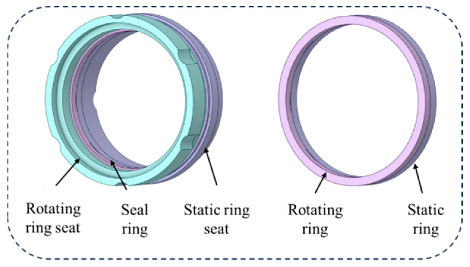
Figure 1. Three-dimensional model of the friction ring.
Machines 12 00680 g001
Figure 2. Boundary conditions loading diagram for friction ring.
Machines 12 00680 g002
Figure 3. Sample specimens: (a) sphere, (b) Ss, (c) C, and (d) SIC.
Machines 12 00680 g003
Figure 4. Friction wear test.
Machines 12 00680 g004
Figure 5. Seal-ring temperature. (a) Dry-friction static ring, (b) dry-friction dynamic ring, (c) mixed-friction static ring, and (d) mixed-friction dynamic ring.
Machines 12 00680 g005
Figure 6. Maximum temperatures of seal faces of different materials.
Machines 12 00680 g006
Figure 7. (a) Total deformation and (b) local deformation.
Machines 12 00680 g007
Figure 8. Thermal axial deformation of sealing ring. (a) Static-ring deformation and (b) dynamic ring.
Machines 12 00680 g008
Figure 9. Trend of axial deformation of soft ring with different materials.
Machines 12 00680 g009
Figure 10. Relative deformation of sealing rings of different materials.
Machines 12 00680 g010
Figure 11. Friction coefficient of different materials.
Machines 12 00680 g011
Figure 12. The wear morphology and 3D visual acquisition and display of SIC.
Machines 12 00680 g012
Figure 13. EDS analysis of the surface of the specimens (a) C, (b) YG8, (c) and graphite-surface elemental energy spectrum.
Machines 12 00680 g013
Table 1. Friction pair seal ring dimensions.
Mechanical Seal ComponentsRadial Dimensions/mmAxial Dimensions/mm
Dynamic-ring inner diameter92.56
Dynamic-ring outer diameter102.56
Dynamic-ring-seat outer diameter11622
Static-ring inner diameter91.57
Static-ring outer diameter105.57
Static-ring-seat outer diameter114.625
Table 2. Boundary conditions of mechanical sealing force.
Stress ConditionsStress Boundary
Spring forceCD
Flushing fluid pressureCD, EF, QR, RS, ST, TU, UV
Flushing fluid pressureVW, WX, XY, YA, AB, BC, VI
Medium pressureFG, GH, HI, IJ, JK, KL
Table 3. Boundary conditions of mechanical sealing thermal.
Thermal ConditionsBoundary
Heating boundaryVI
Flushing fluid convection heat dissipationQR, RS, ST, TU, UV, VW,
WX, XY, YA, AB
Contact convection heat
dissipation of sealing chamber
MN, PQ, BC, CD
Medium convection heat
dissipation
LK, KJ, JI, IH, HG, GF
Table 4. Physical parameters of the rinse solution.
Flushing Solution (Lubrication)Dynamic Viscosity μ/(Pa·s)Thermal Conductivity λ/(W/(m·K))Densities ρ/(kg·m−3)Specific Heat Capacity Cp/(J·kg−1·k−1)
Water1.01 × 10−30.629984179
Table 5. Heat flow density of the friction ring.
Materials Static-Ring Heat Flux Density/W·m−2Rotating-Ring Heat Flux Density/W·m−2
Silicon carbide169,322156,297
Stainless steel175,834149,785
Graphite178,521151,843
Table 6. Dynamic and static-ring convection-heat transfer coefficient.
Heat Transfer Coefficient/W·(m2·°C)−1Rotating Ring (Seat)Static RingStatic Ring Seat
Flushing fluid557142374150
Phosphate slurry860493672
Table 7. Material parameters and mechanical properties.
MaterialsDensity/Kg·m−3Modulus of Elasticity/GPaPoisson’s RatioThermal Conductivity/(W/(m·K))Coefficient of Thermal Expansion/K−1
WC-Co-cemented carbide
(YG8)
15,0007100.234706.9 × 10−6
Stainless steels
(S30408)
79202040.2816.31.6 × 10−5
Silicon carbide
(SIC)
31903800.161004.2 × 10−6
Plumbago
(M106K)
17001300.28901.2 × 10−5
Table 8. Typical material pairing of seal dynamic and static rings.
No.Static-Ring MaterialDynamic-Ring Material
1SsYG8
2CYG8
3SICYG8
Disclaimer/Publisher’s Note: The statements, opinions and data contained in all publications are solely those of the individual author(s) and contributor(s) and not of MDPI and/or the editor(s). MDPI and/or the editor(s) disclaim responsibility for any injury to people or property resulting from any ideas, methods, instructions or products referred to in the content.