Article

RFWBS Model: Multilevel Hybrid Mapping Solution Framework for Designing Neurorehabilitation Physiotherapy Devices

1
Department of Design, Kyungpook National University, Daegu 41566, Republic of Korea
2
School of Art and Design, Yanshan University, Qinhuangdao 066004, China
3
Key Laboratory of Advanced Forging & Stamping Technology and Science, School of Mechanical Engineering, Yanshan University, Qinhuangdao 066004, China
4
Department of Landscape Architecture, Kyungpook National University, Daegu 41566, Republic of Korea
*
Authors to whom correspondence should be addressed.
Machines 2024, 12(1), 43; https://doi.org/10.3390/machines12010043
Submission received: 17 October 2023 / Revised: 15 December 2023 / Accepted: 25 December 2023 / Published: 8 January 2024
(This article belongs to the Section Machine Design and Theory)

Abstract

:
Healthcare services and rehabilitation equipment have entered a phase of rapid development driven by user requirements. However, the development of corresponding design models for rehabilitation equipment is lacking. A general framework and development process are urgently needed for neurorehabilitation physiotherapy equipment. To address problems such as inadequate knowledge representation in the design process and difficulties in modeling the functional structure of the product, we combined a decomposition topology model of neurorehabilitation physiotherapy equipment with the modular design method. We proposed a general model for the design of neurorehabilitation physiotherapy equipment comprising the following modules: requirements (R), function (F), principle workspace (W), behavior (B), and structure (S), i.e., the RFWBS model. Using the neurorehabilitation robotic glove as an example for design practice, in terms of kinematics, the mechanism is analyzed by establishing a Lagrangian coordinate system for resolution. The mechanism has three degrees of freedom and can achieve the natural flexion and extension angles of each finger joint. In terms of dynamics, during the entire finger extension, the angular acceleration is almost zero, and the average angular velocity is approximately 30~50°/s. This indicates that the mechanism is suitable for wearable use, validating the scientific and effective nature of the RFWBS expanded model.

1. Introduction

Neuroplasticity is the ability of the brain to recover and rebuild itself [1,2], and it allows neurons to regenerate both anatomically and functionally and form new synaptic connections [3]. It allows the brain to recover after disease or injury, and it can reduce the effects of structural changes owing to pathological disorders such as multiple sclerosis, Parkinson’s disease, cognitive decline, Alzheimer’s disease, dyslexia, attention deficit hyperactivity disorder, and insomnia. According to the theory of neuroplasticity (Figure 1), reasonable exercise can promote neurological remodeling in stroke patients [4]. Continuous passive motion (CPM) is a rehabilitation method that fits patients with an assistive device so that they can perform prolonged and simulated passive movements of their limbs to improve blood circulation and restore their motor function more quickly [5,6,7]. Clinical applications of CPM theory have successfully restored the limb movements of patients.
Neurorehabilitation physiotherapy equipment is becoming increasingly important for supporting the functional rehabilitation of patients suffering from nerve damage due to strokes and other causes [8]. Such equipment enhances neuroplasticity by controlling limb movements and improving nerve excitation transmission, which increases the recovery capabilities of patients [9]. It is a key tool for addressing major neurological disorders and providing a bridge between doctors and patients [10]. Most rehabilitation for patients with neurological disorders takes place in their homes and communities. Thus, the development of neurorehabilitation equipment that is suitable for use in homes and communities is a critical research issue. However, so far there is no scientifically sound design method for the development of such equipment [11]. Product design knowledge is continuously generated, applied, transformed, and disseminated in various forms during all stages of the design process. Without a proper organization and management structure, researchers will find it difficult to find valuable and relevant knowledge for the design of new products [12,13]. The establishment of a scientifically sound model organizing the relationships and structure of the product design process can provide a better understanding of the generated and transformed knowledge, which will enable more effective knowledge utilization and product design innovation. In this study, we developed a model that divides the product design process into different modules and maps the relationships among the modules. Our objective was to facilitate the development of innovative neurorehabilitation physiotherapy equipment that is suitable for the homes and communities of patients. Gero proposed the FBS model [14,15] to map the relationships between the function, behavior, and structure domains [16]. It presents a rational approach to the product design process and coordinates different variables for innovative product design, as shown in Figure 2. In recent times, various models have been proposed based on the FBS model to describe the rationalized product design and development process in engineering, as well as to coordinate different design variables for innovative product design. Building upon these fundamental models, further research has been conducted to add more dimensions to address more specific issues. The introduction of the Situated FBS framework [17] aims to expand the FBS model and contribute to a better understanding of design in an open, dynamic world. The RFBS [18] model incorporates requirements analysis as a crucial element into the FBS model, proposing integration in design methods and modeling languages. Additionally, the FCBS model [19] seeks a complementary combination of functional and case-based modeling to develop conceptual design support tools. Through reviewing past research and its development, it can be observed that the primary focus has always been on the functional, behavioral, and structural elements of engineering design. The RFWBS model proposed in this study, in comparison to previous models, innovatively incorporates considerations of user requirements and the principle workspace. This new model represents a multi-level mapping innovation process. The RFWBS model approaches engineering design issues from the perspective of knowledge management, emphasizing the capture and representation of knowledge throughout the complete design process.
Neurorehabilitation therapy equipment involves the interdisciplinary integration of multiple disciplines, constituting a complex systems engineering project composed of numerous highly interconnected system modules. Many of these modules exhibit a hierarchical structure themselves, contributing to the complexity of the overall product or system. Currently, there is no comprehensive design model for systematically modeling and solving neurorehabilitation therapy equipment. Delving deeply into the rehabilitation needs of patients is a critical foundation for the design of neurorehabilitation therapy equipment. Additionally, as neurorehabilitation therapy equipment involves various principles, it is necessary to incorporate the principle layer into the constraint scope. Conducting principle space exploration of the principle layer is essential to propose a modular construction method for neurorehabilitation therapy equipment, addressing the aspects of requirements, functionality, principles, behavior, and structure. This facilitates a scientifically and logically sound development process for neurorehabilitation therapy equipment products.
The research in this paper is conducted as follows:
(1)
The existing FBS model has been optimized by incorporating considerations of user requirements and the principle workspace. A fundamental framework supporting conceptual product design modeling has been proposed. This establishes a hierarchical study of complex product modularization within the product architecture, investigating the correlations among functionality, principles, behavior, and structure.
(2)
Multi-level hybrid mapping solutions have been applied to the RFWBS model, studying modular reconstruction design methods. Combining key elements of innovative design for neurorehabilitation therapy equipment, a design support platform for neurorehabilitation devices has been developed, creating a top-down iterative design decomposition model.
(3)
Building upon the product modular design theory of the RFWBS model, the extended RFWBS model has been employed in the design of neurorehabilitation therapy equipment. Addressing product functional requirements, a variant-driven approach has been used to drive the configuration design from user requirements. Taking a specific neurorehabilitation robotic glove as the design subject, the method’s rationality has been validated through kinematic and dynamic analyses.

2. Methodology

2.1. Product Design Processes

2.1.1. Function–Behavior–Structure Model

To solve a complex design problem, one approach is to decompose it into simpler elements that are then layered in turn, starting at a higher level of abstraction [20]. Neurorehabilitation physiotherapy equipment is a complex product with a complicated organization involving multiple disciplines. Modular identification is based on identifying complex products as a series of modules and connections that can then be configured to achieve the product structure [21].
The design process is a creative activity that translates needs into matter by harmonizing the basic laws of man and product [22]. In the Internet age, models are necessary for processing design information and building design strategies. The function–behavior–structure (FBS) model has emerged as a representative framework for describing design processes and tasks [23], which has had significant implications for the introduction of knowledge modeling into the product design process [24,25].
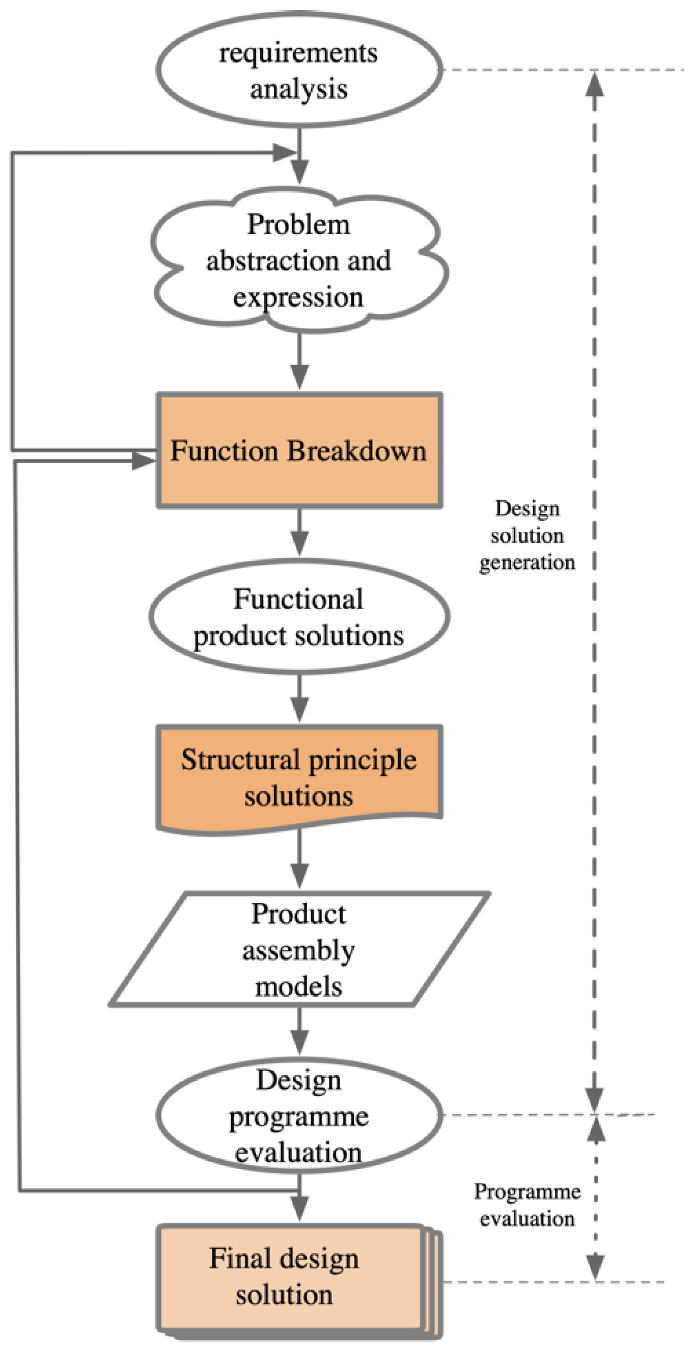
The many-to-many mapping relationships of the FBS model can help designers gradually decompose the overall function of a product and map out different behaviors. Then, the designer can use the behaviors to reorganize the structure of the product to solve the design objective [26]. The FBS model facilitates the optimization of the entire design process and is close to the human cognitive process of product design [27], as shown in Figure 3. The importance of utilizing functionality in the design process is widely recognized [28,29,30]. The design process involves developing a structure that performs the function required by the product. To some extent, the function–structure matching problem has been solved by functional solution strategies [31]. However, most of these methods map the function and structure at a single level, which likely produces a large number of redundant solutions and makes it difficult to obtain a satisfactory design.

2.1.2. Ontology-Based Product Design

The design process is an organizational activity that integrates the resources of all stakeholders to achieve a goal, and the acquisition and updating of knowledge between stakeholders and design activities are constantly changing. Ontology-based models are essential for the design of innovative products. An ontology-based FBS model can establish tasks for product design based on user requirements and a knowledge base including product constraints, features, and structures. The design tasks can be developed into modules for generating several alternative solutions, from which the optimal design can be selected. The core elements of a modular product design system include module division, module identification, and mapping solutions. The FBS model can be extended to support modular product design, which requires establishing a module-related matrix and dividing modules into a hierarchy from coarse to fine [32]. In modular product design, the mapping of behaviors to structure is not the final step because a large number of solutions may be obtained that require reconfiguration of the modules until the final solution is obtained [33]. Figure 4 shows the decomposition of the modular product design system.

2.1.3. Knowledge System Framework

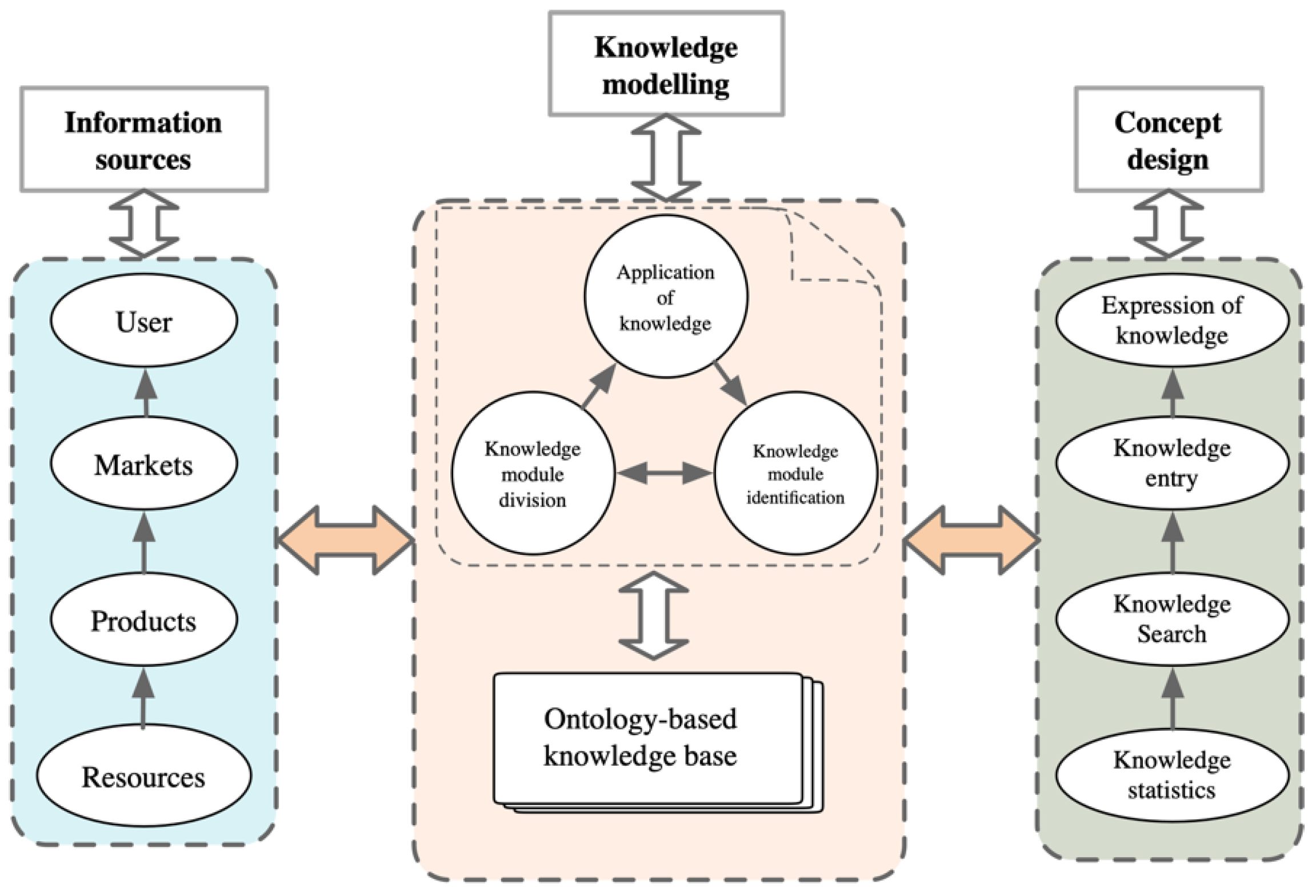
Product design is a process that starts from user requirements and ends with a series of solutions based on various methods, theories, tools, and instruments. The design of a knowledge system framework is a left-to-right building process: knowledge flows from the user and market environment, modules are built based on knowledge-based ontology, the modules are used to establish a model, and this model is used for circular mapping of modules and applications before the product design is finally completed. A knowledge system framework provides theoretical support for mapping strategies based on the ontology [34] and gives the designer a macroscale perspective of the product design process, as shown in Figure 5.

2.2. Proposed Model

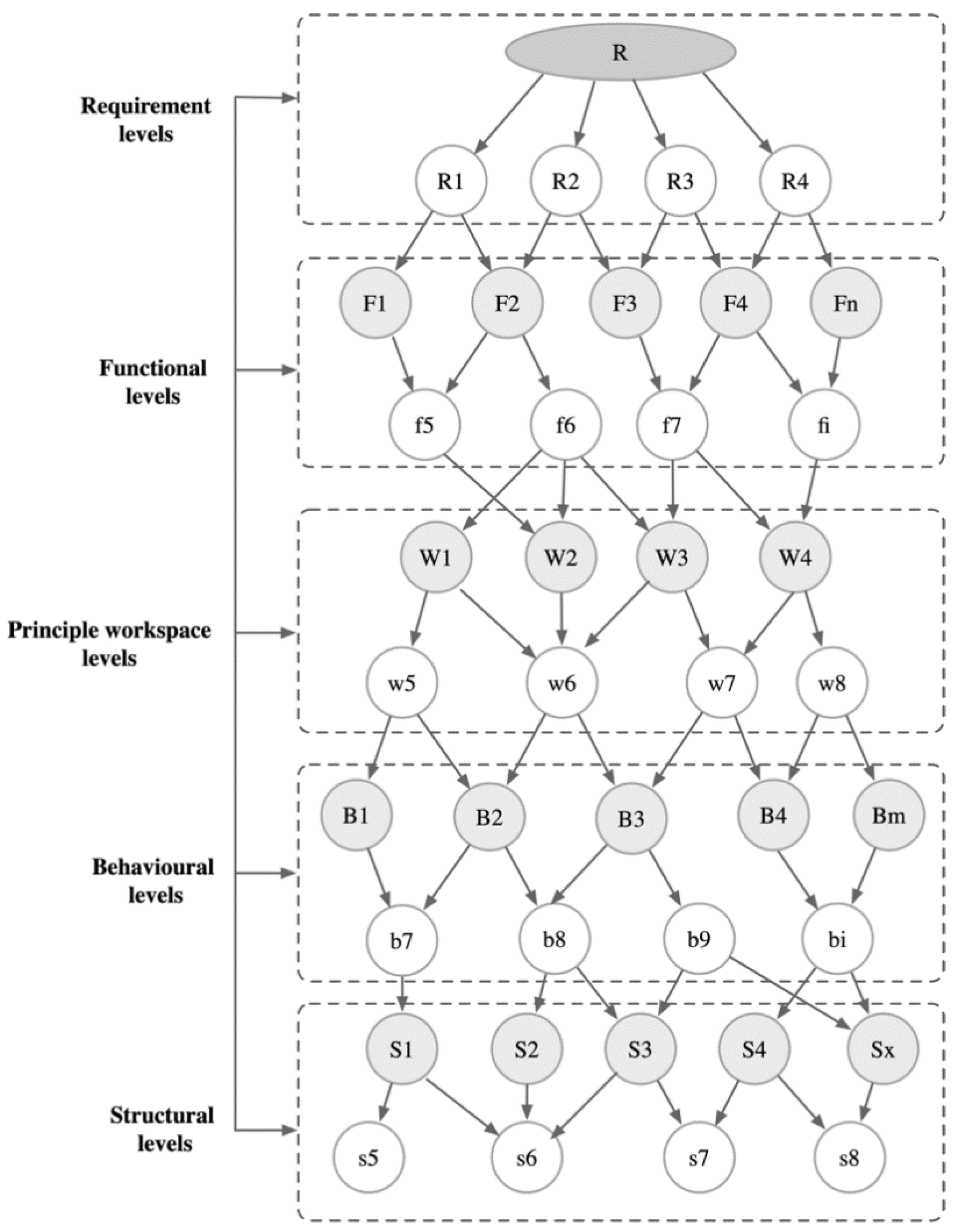
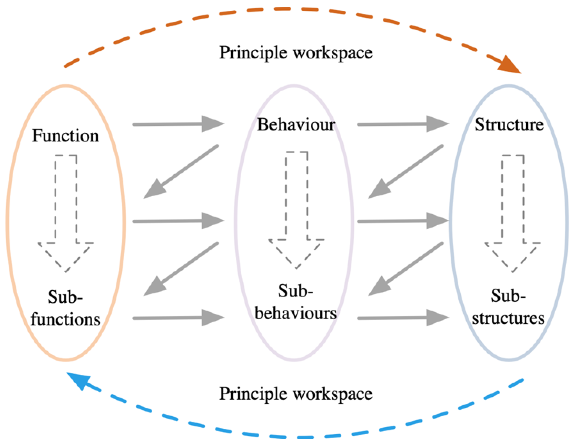
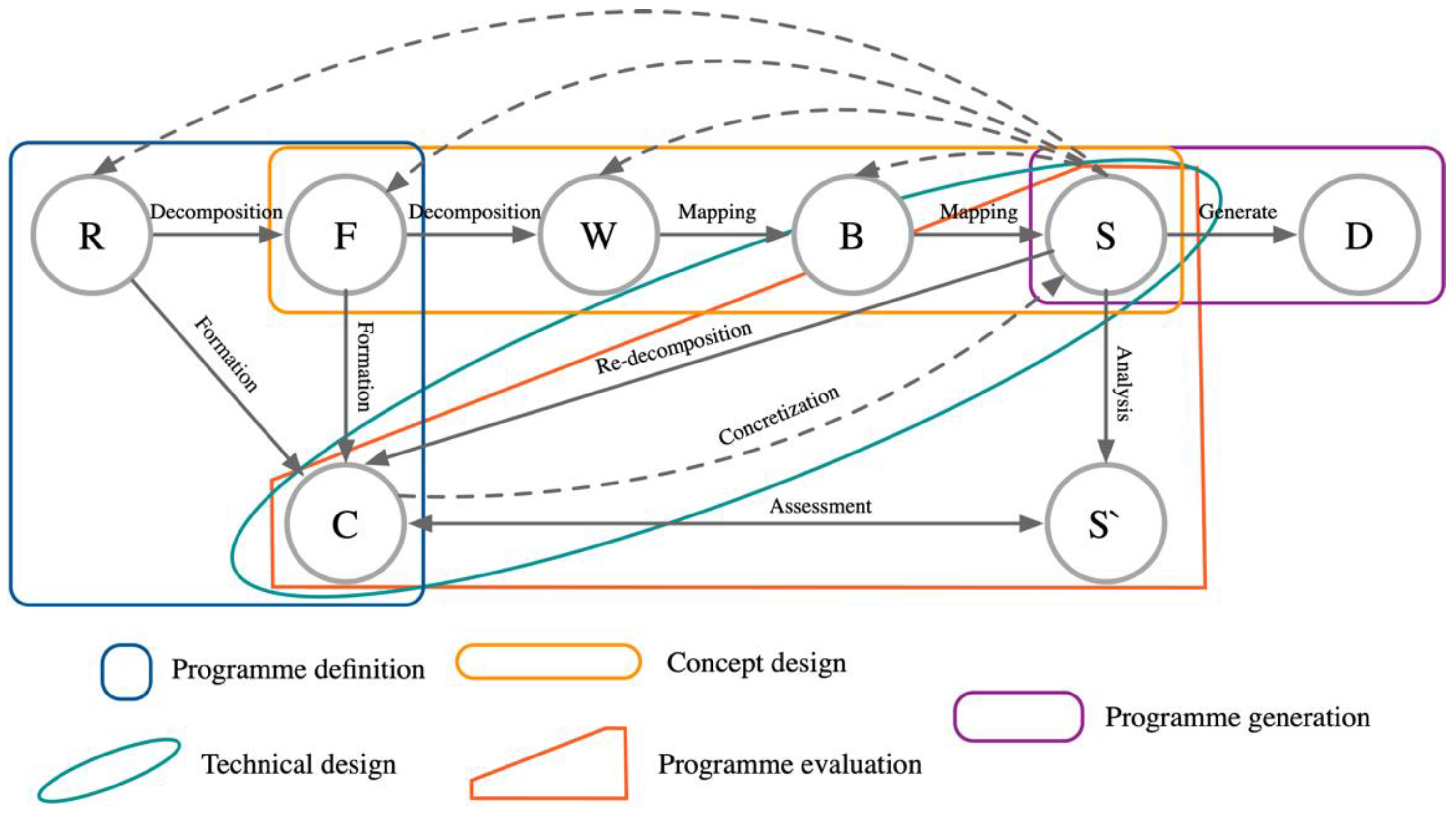
Our proposed model is very similar to the human cognitive process and facilitates the design of innovative products. As shown in Figure 6, the RFWBS model is an iterative design process that integrates requirement, functional, principle, behavioral, and structural layers. The design process takes the user requirement layer as the starting point. The functional layer matches the user requirements to certain principles to obtain specific functional elements. We cannot map the functional layer directly to the behavioral layer owing to a lack of a scientifically sound approach, and neurorehabilitation physiotherapy equipment involves knowledge of different principles. Thus, we include the principle workspace layer to add constraints. We can then map the principle workspace layer to the behavioral layer, which we then map to the structural layer to derive a product design solution. We can construct a closed-loop mapping approach and a reasonable mapping hierarchy between various modules to adapt the process to the design of neurorehabilitation physiotherapy equipment.

2.2.1. User Requirements Module

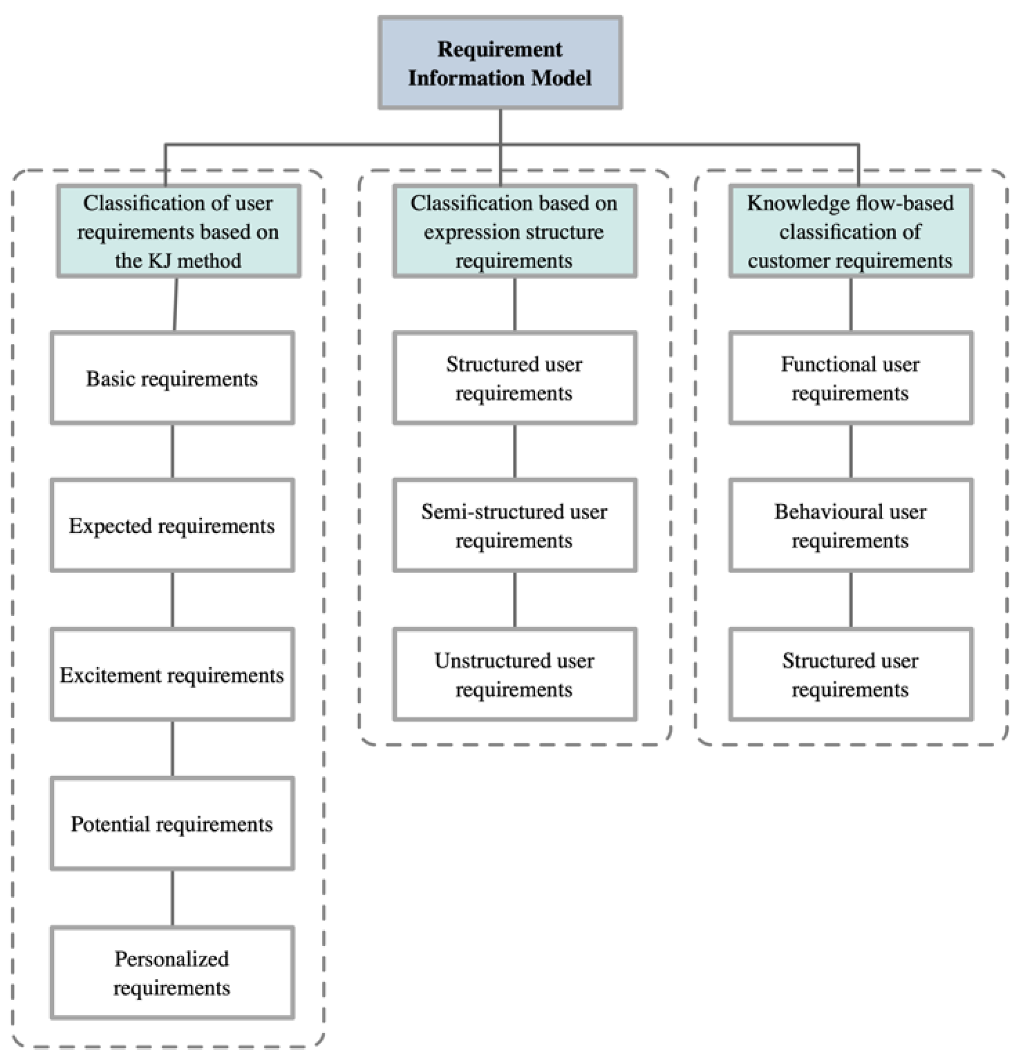
The design of neurorehabilitation physiotherapy equipment is a complex process, and meeting user requirements is a primary consideration that determines the competitiveness of a product. Various aspects influence user requirements such as the environment, market, politics, and technology. Therefore, effective analysis and collation of information and the acquisition, definition, and decomposition of requirements are a prerequisite for the product design process. User requirements can be divided into two categories: basic and secondary. Basic requirements represent the fundamental and nonnegligible requirements; secondary requirements are derived from the basic requirements. The acquisition of user requirements is a prerequisite for product design. We classified and represented user requirements using the KJ (Affinity Diagram) method, as shown in Figure 7. This model defines functionality as an association between user requirements and behaviors, which is represented hierarchically. The RFWBS model provides a structured representation of the product design process and improves the modular approach by incorporating knowledge of user requirements in the iteration process.
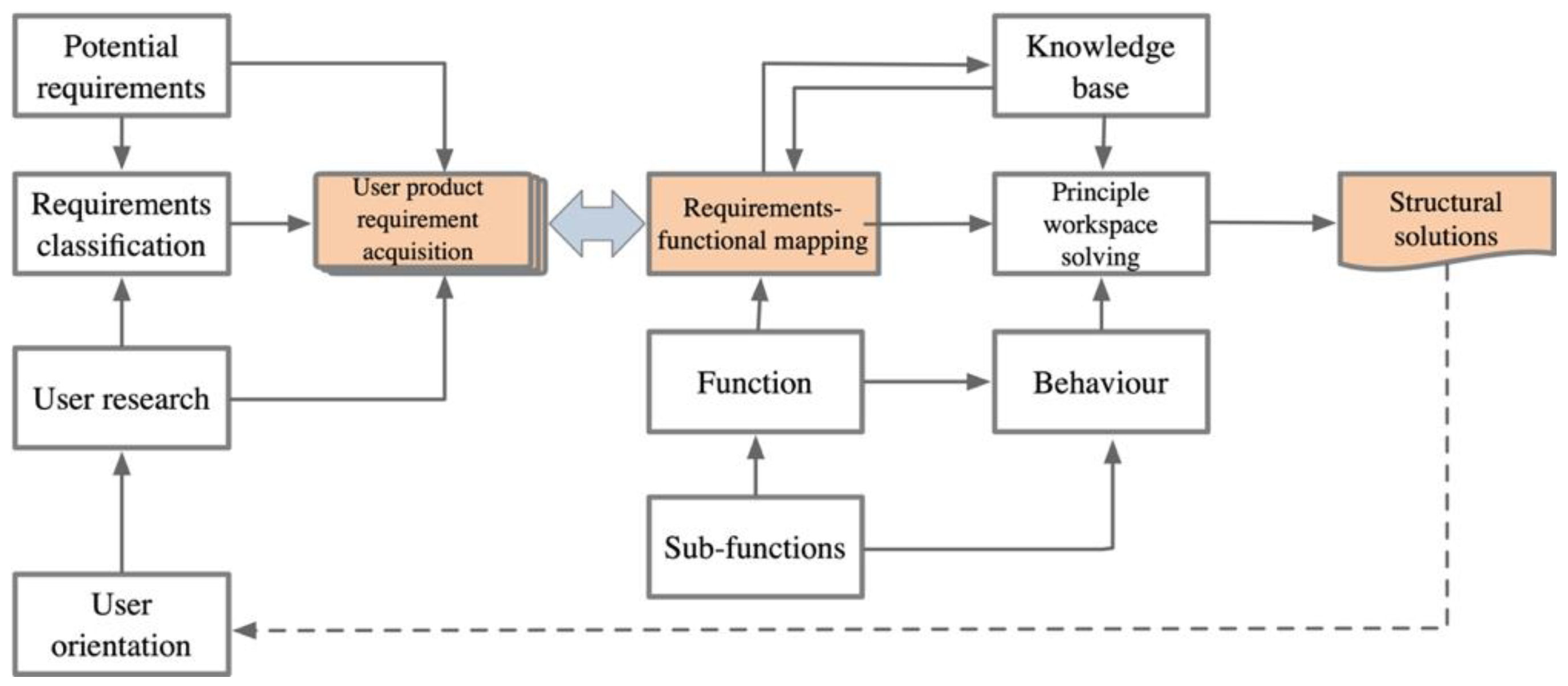
The effective acquisition of user requirements determines the success of innovative product design, and functional decomposition requires the classification of user requirements as constraints to obtain a feasible functional organization scheme. User requirements also constrain the mapping of the principle workspace module and structural module to obtain a satisfactory product design. Figure 8 shows the relationship between user requirements and structural solutions.

2.2.2. Functional Innovation and Behavioral Modules

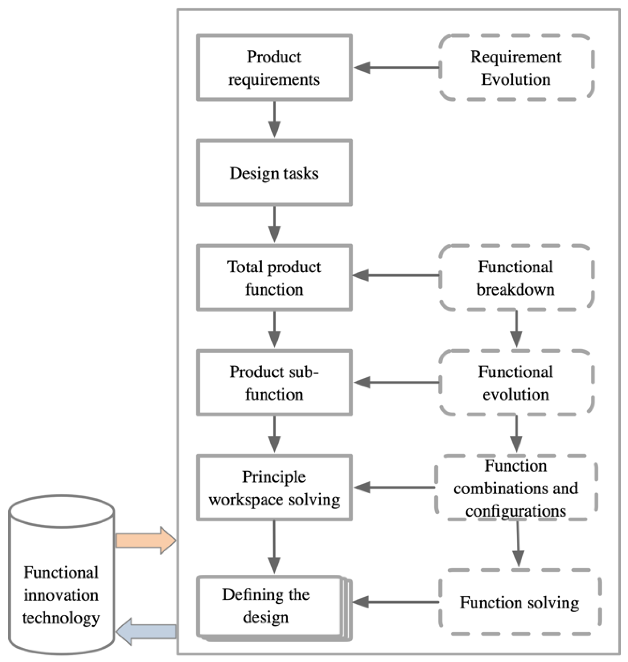
Neurorehabilitation physiotherapy equipment involves the cross-fertilization of many disciplines, which results in a high degree of coupling between modules and makes modular management difficult. In the functional innovation module, the product function should be clearly defined. Then, the function should be decomposed into functional elements for which individual solutions can be obtained. Then, the principle workspace module should be constructed to constrain the functional innovation module. The evolution of user requirements, the optimization of functional element combinations, and the solution of the principle workspace can be incorporated to realize a more systematic product design process. As shown in Figure 9, the introduction of key techniques in the functional innovation module facilitates a scientifically sound approach to the iterative design of neurorehabilitation physiotherapy equipment.
Neurorehabilitation equipment comprises technical systems of different structures that fulfill specific purposes in specific contexts. A behavior is a description of the concrete manifestation of a function, and a function is mapped to a behavior based on the input and output processes. Matching a behavior to a function is an important step in the design of complex products. The behavioral module is constructed by linking the principle workspace module to the functional innovation module. The specific steps include defining behaviors, interpreting the results of pairing behaviors to corresponding basic functions, and then linking a behavior to the corresponding structure. The behavioral module is a key node of the product design system. The behavioral module can be used as a constraint to represent user requirements more intuitively and verify the rationality of the product design process.

2.2.3. Principle Workspace Module

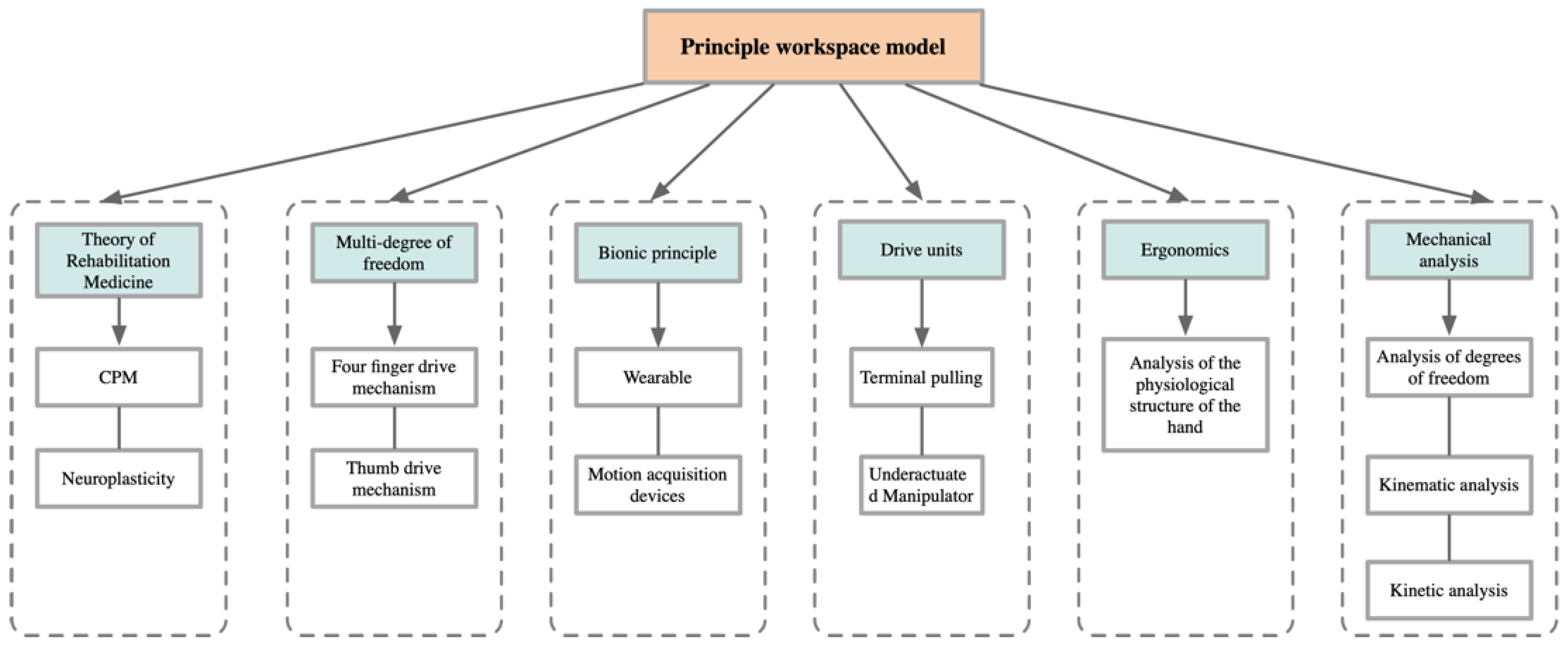
Principles are basic laws that express the internal connections of things and are a scientifically sound approach to defining the function of a product. As shown in Figure 10, the principle workspace module is mapped from the functional innovation module as a constraint on the complex product design process and is the bridge linking functions and behaviors. The principle workspace module reflects the essential internal characteristics of the product and expresses the knowledge of various constraints to control the product design process. We can apply circular mapping between the functional innovation module and the principle workspace module. Functional independence ensures that the product meets user requirements with minimal design modification, which reduces design costs.
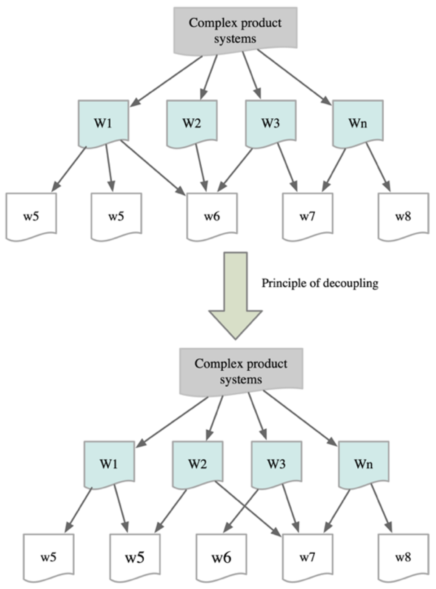
The diversity of functional mappings means that the principle workspace module also has different properties. In the user domain, the principle workspace module can describe the physical structure of a body part and is a concrete representation of the user requirements. In the product function domain, the principle workspace module expresses a specific path to achieve a function. In the product structure domain, the principle workspace module expresses the specific technologies required to realize a structure. As shown in Figure 11, the design process for complex products requires the decoupling of the principle workspace module into certain principles.

2.2.4. Structural Module

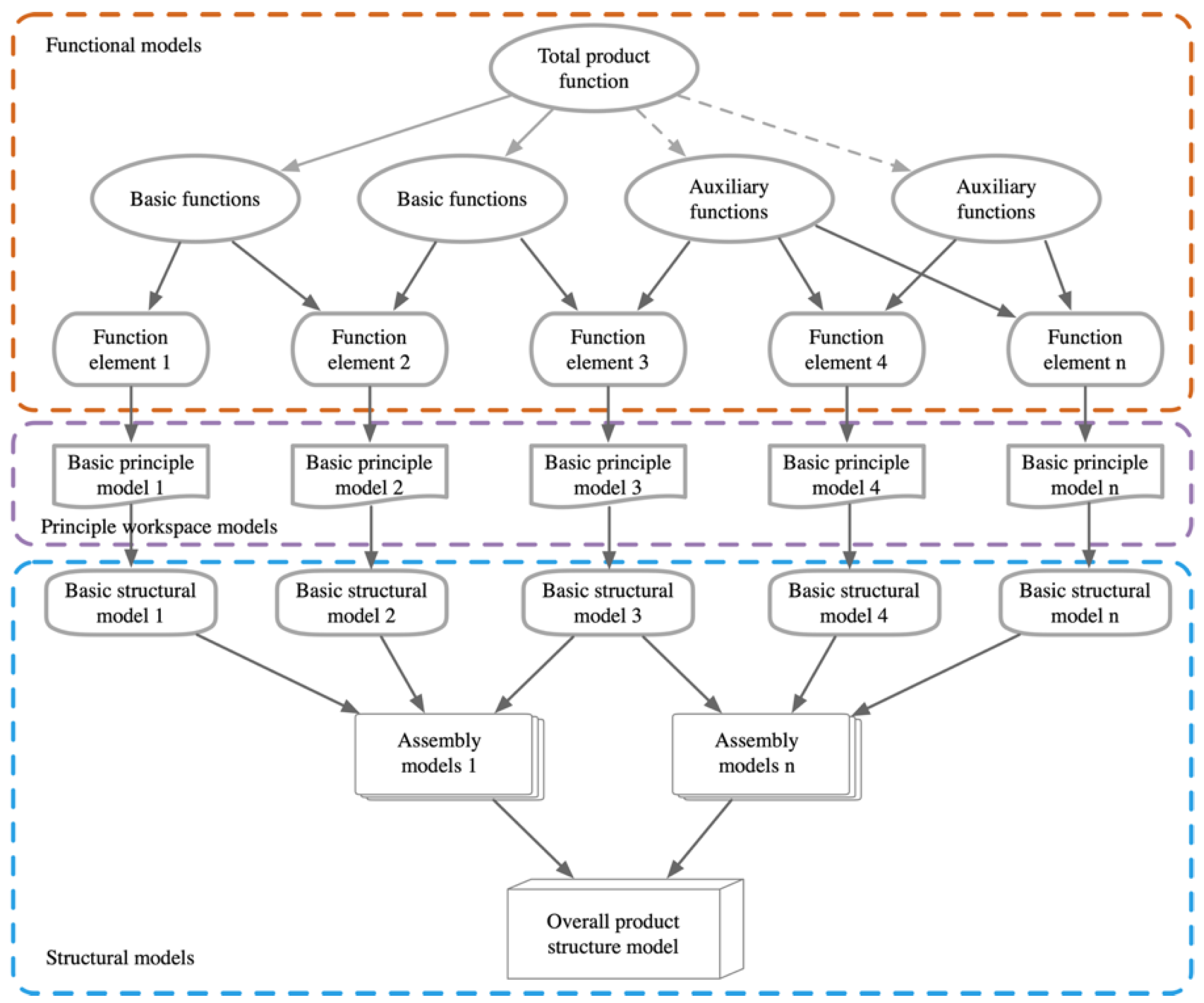
The structural module is the final mapping of the function and is realized by linking the principle workspace module and behavioral module. A hierarchical identification study is carried out from the total system to the subsystems and components, and the overall product is derived from the hierarchical relationships between structures and their assembly. This process requires ensuring certain relationships between internal structures and relative independence for the overall structure. Assembling a product model requires mapping modules to match each other and optimizing their combination. The objective is to reduce the number of modules and reduce the complexity of solutions to facilitate the selection of the best solution from a small number of solutions, which would improve design efficiency. Figure 12 shows the structural module and the topological relationships between modules that allow the rapid construction of a framework for generating a structural solution.

2.2.5. Iteration-Based RFWBS Model

Our proposed RFWBS model introduces the concepts of module identification and classification to establish an iteration-based modular framework for designing complex products. Personalized product design requires access to user requirements and behavioral sequences. However, the FBS model is deficient in obtaining knowledge of user requirements and principles. Therefore, we constructed the RFWBS model to incorporate user requirements and a principle workspace. Then, we mapped a solution strategy for incorporating requirements, functions, principles, behaviors, and structures in a dynamic design process. Figure 13 maps the knowledge flows and constraints between the various levels of the RFWBS model. C in the figure represents the conceptual design and D represents the design solution.

3. Application to Neurorehabilitation Manipulators

3.1. Analysis of User Requirements Dimensions

The subjects selected for this user study were stroke patients with hand movement disorders, their family members, and medical staff from the rehabilitation department. As it is challenging to access the target group in ordinary life situations, in the preliminary research phase, apart from literature studies, on-site investigations were conducted in the hospital’s rehabilitation department and patients’ homes.
The fundamental purpose of user research is to investigate user requirements and provide design guidance for specific design projects. Common qualitative analysis methods for such investigations include observational methods and interview methods. Observational and interview methods are frequently used qualitative analysis approaches that can collect a significant amount of on-site data and user-expressed text. Combining these two methods often yields better research results. Through on-site visits and research on stroke patients, we have established a basic understanding of the target user group using observational and interview methods, as shown in the figure below.
This study primarily employed observational methods to investigate the hand rehabilitation training process of stroke patients and used interview methods to interview users with high levels of cooperation. Observational methods were used to record the process of users using the product in real scenes and analyze user confusion and problems. This research, aiming to avoid early constraints on study factors, adopted an unstructured observational approach in qualitative research. Unstructured observation can collect a large amount of data, including pictures, recordings, videos, etc. The recorded text is mainly descriptive, allowing researchers to observe the complex and intricate interactions between humans, machines, and the environment, providing rich material for innovative design.
The KJ (affinity diagram) method was employed to summarize and classify various types of data obtained through observational and interview methods. This transformed a large amount of descriptive text into a clearer structural framework, as shown in the table. The structural framework divides user requirements into two dimensions: basic requirements and auxiliary requirements, totaling eight user requirements, denoted as Ri (i = 1, 2, …, 8). Among them, the basic requirements dimension includes safety stability, neurorehabilitation, human-computer interaction, and user comfort; the auxiliary requirements dimension includes ease of wearing, assistance in rehabilitation, aesthetic rehabilitation, and personalized requirements. As shown in Table 1.

3.2. Module Configuration

The acceleration of digitalization and advances in healthcare services have increased opportunities for neurorehabilitation aids [35]. Neurorehabilitation physiotherapy equipment can be effective in supporting patients or compensating for their functional deficits. Most current rehabilitation robots are rigidly driven, uncomfortable to wear, and difficult to control; moreover, they lack adaptability and have a limited movement space. Thus, an exoskeleton hand robot is needed that can seamlessly perform human–machine interactions and fully drive hand joints as well as have a large movement space. We constructed a closed-chain cascade wearable exoskeleton hand robot that includes a four-finger drive mechanism, thumb-drive mechanism, hand back plate, motor pallet, and motor. Figure 14 shows the principle workspace module of the neurorehabilitation manipulator.
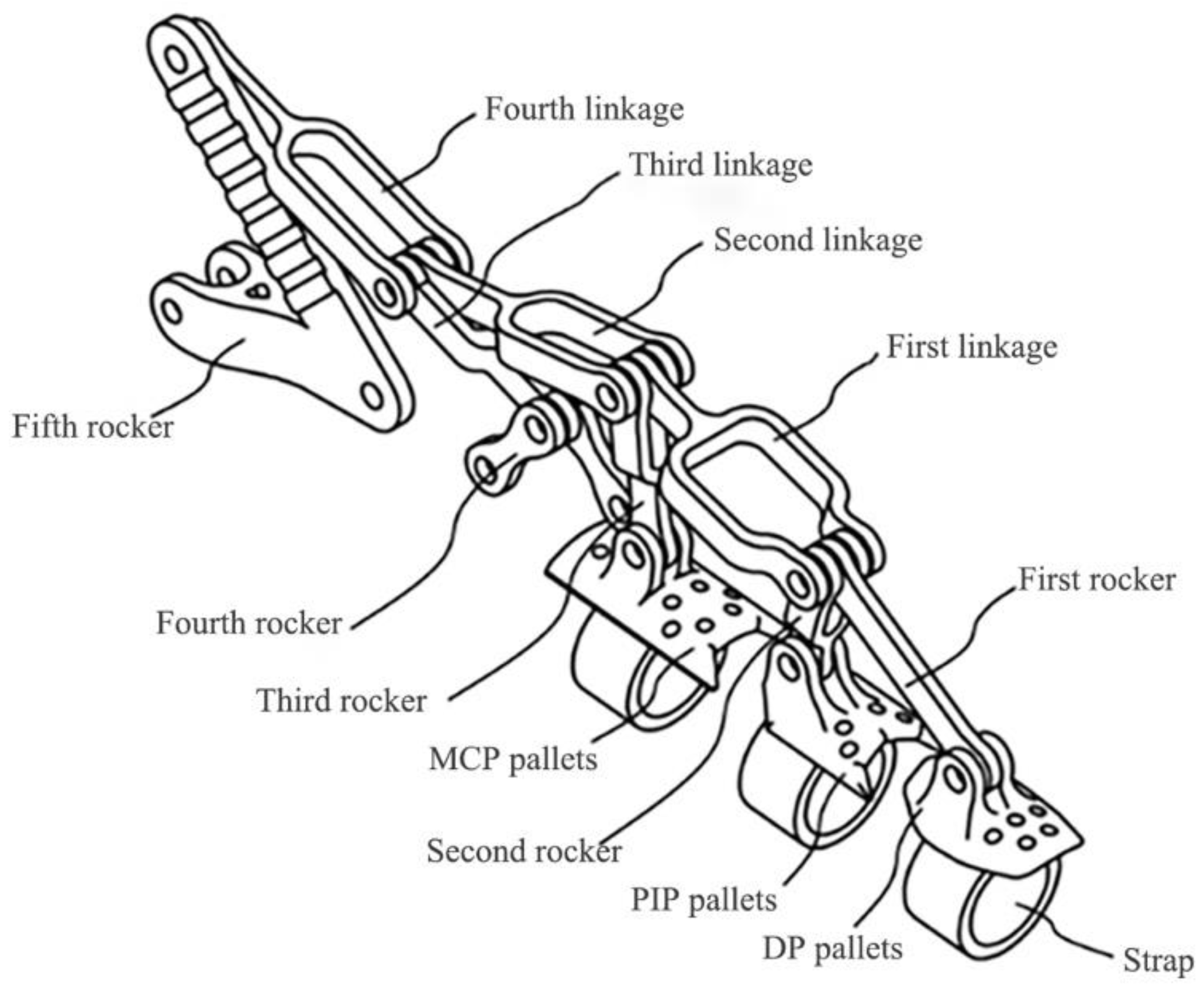
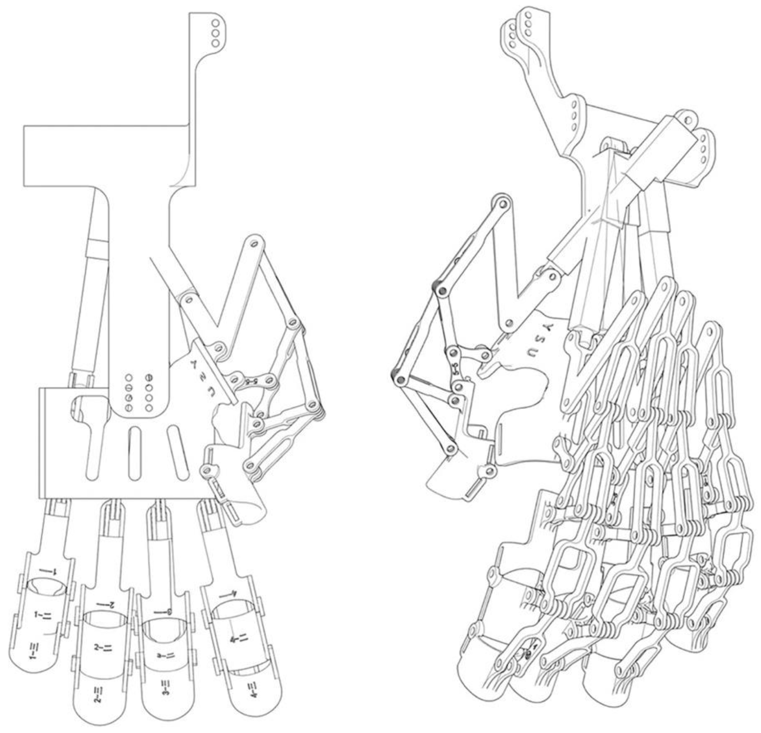
Figure 15 shows a schematic diagram of the four-finger drive mechanism, which includes a pallet set, rocker set, linkage set, and strap. The index, middle, ring, and little fingers each have a movement aid. The length ratio of the four fingers determines the lengths of the components of the corresponding movement aids, but the structures of the movement aids are exactly the same.
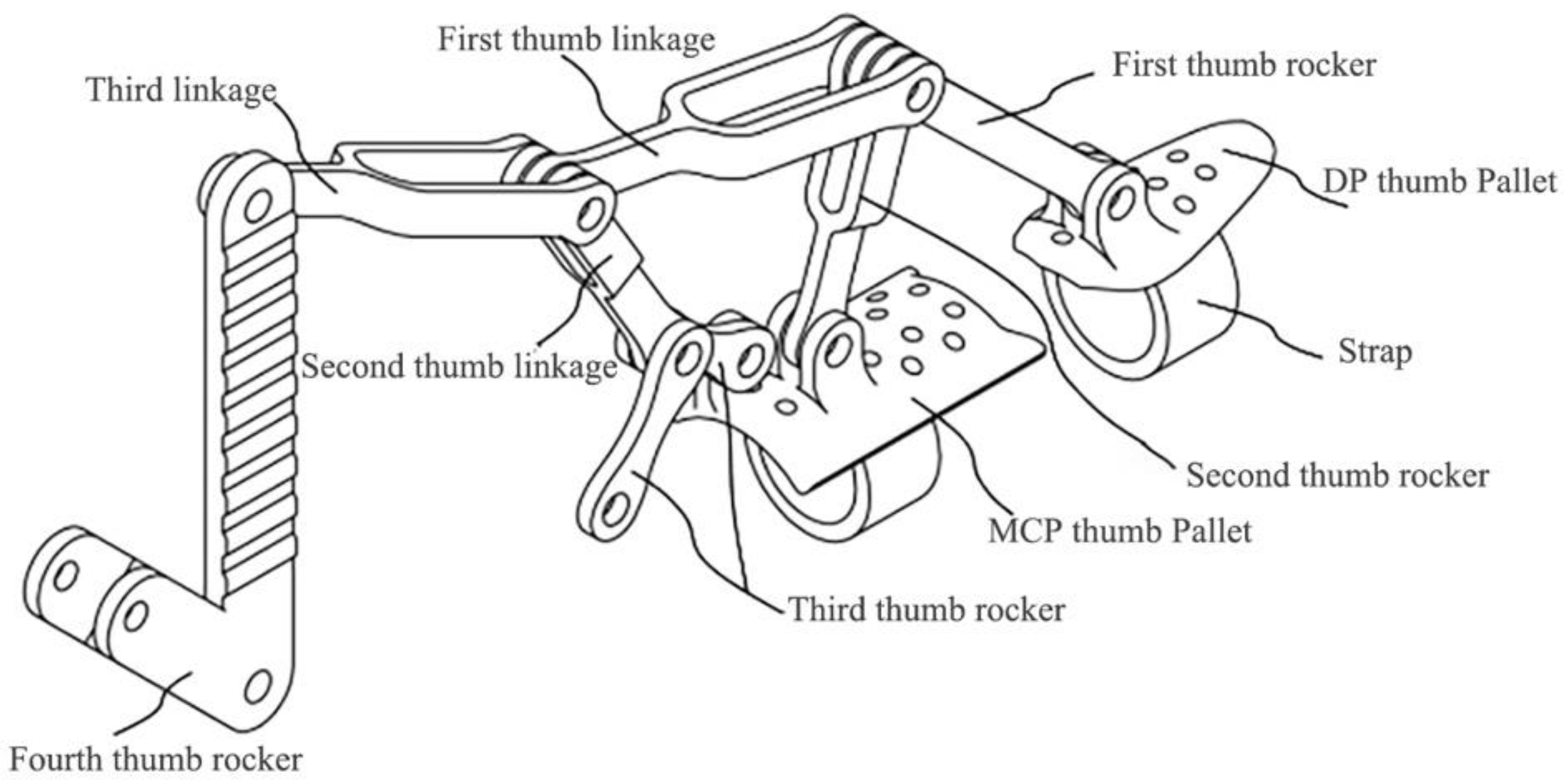
Figure 16 shows a schematic diagram of the thumb-drive mechanism, which comprises a thumb rest set, thumb rocker set, thumb link set, and strap. The thumb rest set comprises a metacarpophalangeal (MCP) rest and interphalangeal (IP) rest, where the former is on the proximal end of the thumb and the latter is on the distal end. The thumb rocker set comprises four thumb rockers.

3.3. Mapping of the RFWBS Model to the Neurorehabilitation Manipulator

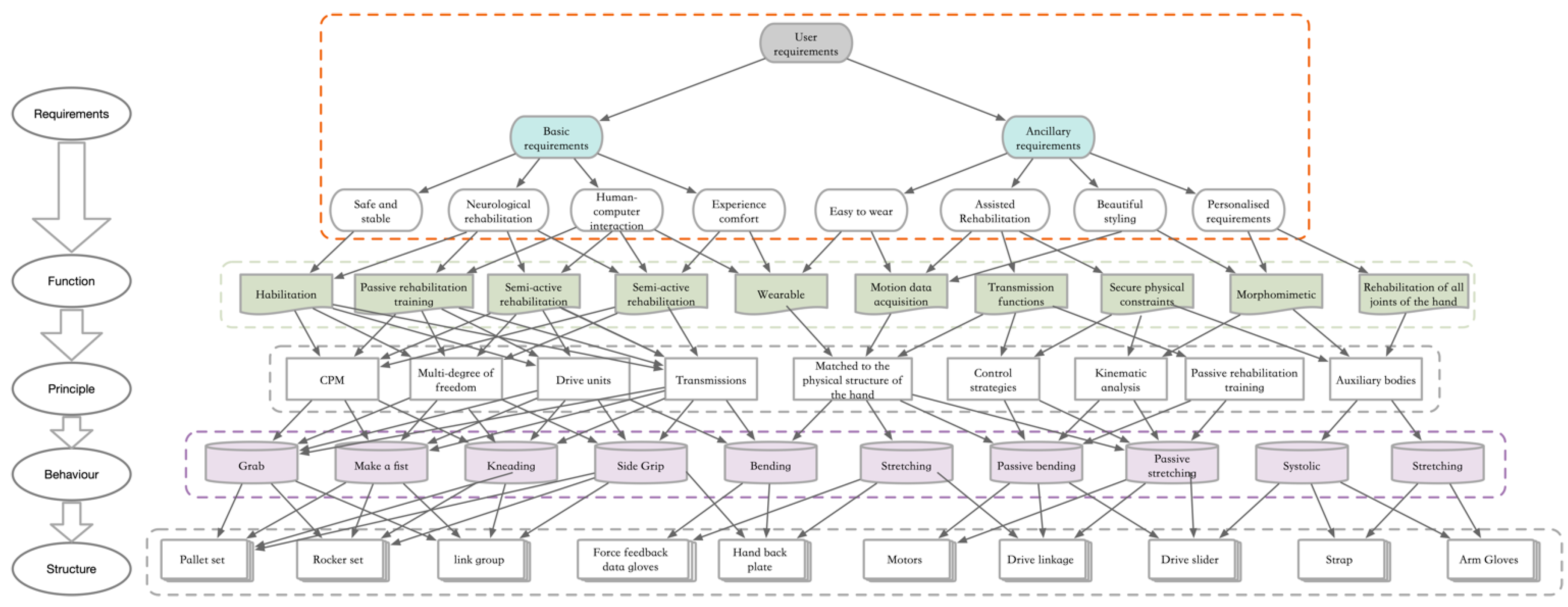
We developed a top-down design process for the neurorehabilitation robotic glove to analyze the user requirements and map them to functions. Then we divided the robotic glove into modules and applied the proposed RFWBS model to obtain a design solution. We classified the functional abstraction layer of the neurorehabilitation robotic glove in unit dimensions and divided the functional elements into a meta-functional layer and functional object layer. We then classified the functional elements as adaptive training, passive rehabilitation training, semiactive rehabilitation training, active rehabilitation training, wearable functions, and motion acquisition functions. We divided the behavioral elements into behavioral blocks and behavioral chains. The behavioral chains included series of actions such as grasping, fist clenching, side grip, bending, and stretching. We mapped actions with similar behavioral characteristics to independent structural characteristics according to the principle of behavioral compatibility. We constrained the topology of the structural module according to the relationships and attributes of component structures to establish a hierarchical model, which can be divided into a structural component layer (e.g., drive linkage, small arm glove, DC motor) and a structural relationship layer (e.g., electromechanical activity extraction sensor, force feedback data glove). Figure 17 shows the complete mapping solution of the neurorehabilitation robotic glove based on the proposed RFWBS model.

3.4. General Structural Configuration

Figure 18 shows the internal structure of the designed neurorehabilitation robot robotic glove comprising the following parts from top to bottom: motor and controller, four-finger drive mechanism, thumb-drive mechanism and transmission lines, hand back plate with myoelectric activity sensors, and strapping.
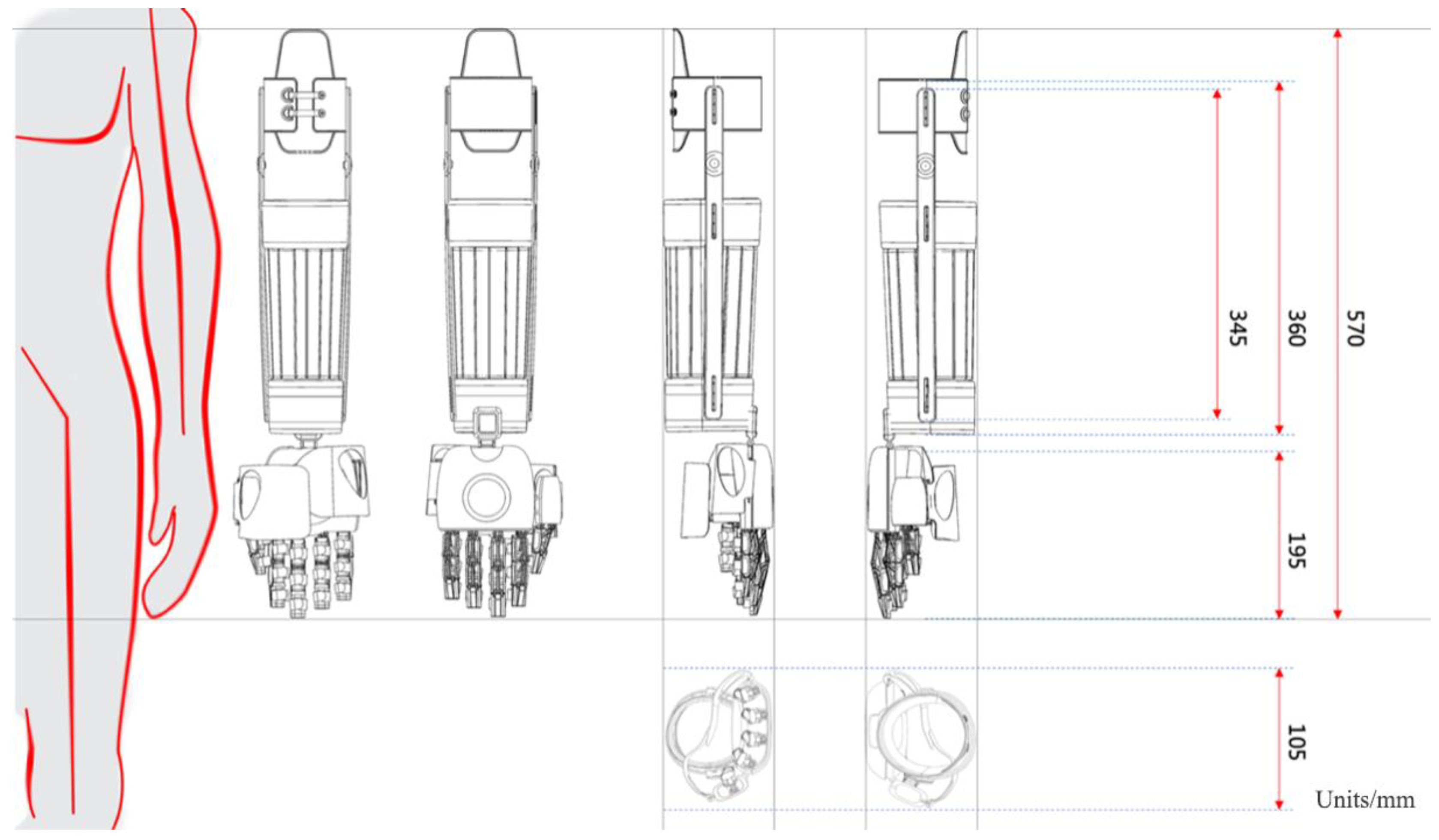
The design solution provides a closed-chain cascade wearable exoskeleton manipulator. In the four-finger drive mechanism, the pallet set hinges to one end of the rocker set. The other end of the rocker set hinges to the linkage set. There is mutual articulation between linkage sets. In the thumb-drive mechanism, the pallet set hinges to one end of the rocker set. The other end of the rocker set hinges to the linkage set. There is mutual articulation between the linkage sets. The four-finger drive and thumb-drive hinge to the hand back plate. The hand back plate connects to the motor pallet. The motor is placed in the corresponding motor slot and hinges to the motor pallet, four-finger drive, and thumb drive in sequence. The motor pushes the four-finger drive mechanism and thumb-drive mechanism. The drives in turn push the proximal and distal ends of the human thumb through the thumb pallets to complete the activities of the MCP and IP joints of the thumb and the proximal, middle, and distal ends of the other four fingers through their pallets to complete the activities of the MCP, IP, and distal interphalangeal (DIP) joints of the other four fingers. In summary, the closed-chain cascade wearable exoskeleton robotic glove assists the user with the activities of each finger joint and contributes to rehabilitation or activities of daily living using the hand. Figure 19 shows a diagram matching the neurorehabilitation robotic glove to a human hand.

3.5. Neurorehabilitation Robotic Program Generation

We have finalized the design of the neurorehabilitation robotic glove based on the above analysis. Based on the target user requirements, we applied the RFWBS model to map the functional elements, select the best solution, and design the structure. We designed the wearable neurorehabilitation robotic glove based on CPM theory and the principles of multiple degrees of freedom and underdrive. This allows the robotic glove to facilitate comfortable, precise, and stable rehabilitation training and to flexibly switch between active and passive training modes for task-oriented rehabilitation and training for five-finger coordination. The actuation module of the neurorehabilitation robotic glove can be rapidly replaced through modular implementation, enabling customized design for different patients and meeting the requirements of various human–machine dimensions. The structural module is designed to be fault-tolerant and self-healing, which allows for easy replacement of easily damaged parts of the wearable neurorehabilitation manipulator. For example, the straps in contact with the human body are easily soiled and damaged, so the modular design facilitates their cleaning and replacement. Figure 20 and Figure 21 show the final rendering of the neurorehabilitation manipulator, and Figure 22 shows the internal structural details.

4. Simulation for Verification

4.1. Kinematic Model

We performed kinematic and kinetic analyses on the developed neurorehabilitation robotic glove to evaluate the scientific validity and effectiveness of the RFWBS model. The first concern for neurorehabilitation manipulators is safety. The design of the robotic glove should consider functional requirements while preventing secondary injuries. To ensure patient safety, we needed to analyze the mechanical design and control system. We developed a behavioral kinematic model to prevent the neurorehabilitation robotic glove from causing secondary injuries to the patient. Prior to the modeling, we made the following assumptions:
(1)
Friction factors are negligible.
(2)
The relative displacement between the human hand and neurorehabilitation robotic glove can be ignored.
(3)
The voluntary movements of the IP joint of the thumb and DIP joints of the remaining four fingers are negligible.
(4)
The movements of the four fingers and thumb are synchronized.

4.2. Analysis of the Degrees of Freedom

As a prerequisite to analyzing the kinematics and dynamics, we needed to analyze the degrees of freedom first. Various methods are available for analyzing the degrees of freedom of a planar mechanism, of which a common one is the Chebyshev–Krubb formula (Grübler–Kutzbach):
F = 3 ( N 1 ) 2 P S = 3 M 2 P S
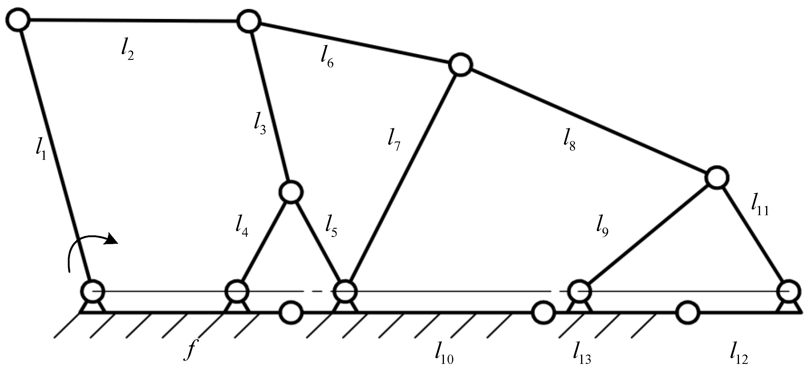
where PS is the number of low subs and N is the number of components (including the frame). The design of the body has multiple compound subs, so using this method to solve for the degrees of freedom is tedious and prone to error. Thus, we chose to use Rasch coordinates and the constraint equation relationship to determine the degrees of freedom. The first step was to establish the coordinate system. Generally, the analysis of a constrained system consisting of the mass system and rigid body uses the right angle and polar coordinate systems. However, the complexity of the constructed neurorehabilitation robotic glove means that it has a large number of links and articulations with multiple closed-chain loops. Thus, we used the Lagrangian coordinate system. Figure 23 shows a schematic of the simplified mechanism of a Lagrangian coordinate system, which we used for our analysis of the degrees of freedom.
The mechanism has 13 movable members (l1l13). There is one rack with a length f. There are five closed-chain loops, where Loop 1 is a five-link (containing one rack) mechanism, Loop 2 is a four-link (containing one rack) mechanism, Loop 3 is a four-link mechanism, Loop 4 is a five-link mechanism, and Loop 5 is a four-link mechanism. The overall mechanism has 20 Lagrangian coordinates: φ1, φ2, …, φ13 and φ 3 , φ 4 , φ 5 , φ 6 , φ 8 , φ 10 , and φ 11 , where φ 3 , φ 4 , φ 5 , φ 6 , φ 8 , φ 10 , and φ 11 are linearly correlated with φ3, φ4, φ5, φ6, φ8, φ10, and φ11, respectively. Thus, there are 13 linearly uncorrelated Rasch coordinates in total.
The complete Rasch coordinate system and equations are as follows:
{ l 1 cos φ 1 + l 2 cos φ 2 + l 3 cos φ 3 + l 4 cos φ 4 = f 1 l 4 cos φ 4 + l 3 cos φ 5 + l 3 cos φ 6 = f 2 l 5 cos φ 5 + l 3 cos φ 3 + l 6 cos φ 7 + l 7 cos φ 8 = 0 l 7 cos φ 8 + l 8 cos φ 9 + l 9 cos φ 10 + l 10 cos φ 11 + l 6 cos φ 6 = 0 l 9 cos φ 10 + l 11 cos φ 12 + l 12 cos φ 13 + l 13 cos φ 11 = 0
{ l 1 sin φ 1 + l 2 sin φ 2 + l 3 sin φ 3 + l 4 sin φ 4 = 0 l 4 sin φ 4 + l 3 sin φ 5 + l 3 sin φ 6 = 0 l 5 sin φ 5 + l 3 sin φ 3 + l 6 sin φ 7 + l 7 sin φ 8 = 0 l 7 sin φ 8 + l 8 sin φ 9 + l 9 sin φ 10 + l 10 sin 11 + l 6 sin φ 6 = 0 l 9 sin φ 10 + l 11 sin φ 12 + l 12 sin φ 13 + l 13 sin φ 11 = 0
In total, there are 10 constraint equations, and they are linearly independent. Therefore, the degrees of freedom of the body are
F = M C = 13 10 = 3
The degrees of freedom of the kinematic subchain in Loop 1 are
F 1 = M 1 C 1 = 4 2 = 2
The degrees of freedom of the kinematic subchain in Loop 2 are:
F 2 = M 2 C 2 = 3 2 = 1
The degrees of freedom of the kinematic subchain in Loop 3 are
F 3 = M 4 C 2 = 4 2 = 2
The degrees of freedom of the kinematic subchain in Loop 4 are
F 4 = M 4 C 4 = 5 2 = 3
The degrees of freedom of the kinematic subchain in Loop 5 are
F 5 = M 5 C 5 = 4 2 = 2
The degrees of freedom of each kinematic subchain are related to the degrees of freedom of the overall mechanism by F i ( 0 , F ) and i = 1, 2, 3, 5. Therefore, the mechanism has partial freedom.

4.3. Kinematic Analysis

We applied kinematic analysis to solve for the end position of the neurorehabilitation robotic glove based on each known joint angle, which involves a transformation from joint space to Cartesian space. In this study, we solved the bending angle and end position of each joint for a known motor push length. The previous analysis on the degrees of freedom showed that the overall mechanism has three degrees of freedom. When the length of the motor push is known, the position of the member l1 becomes known, so φ1 in turn becomes known. However, there are still two independent Rasch coordinates (i.e., generalized coordinates), so the motion attitude of the mechanism cannot be determined. Based on the actual movement of the human fingers, the two local links are selected in steps to constrain the target link (end joint) to an existing kinematic posture. First, Figure 24 shows the MCP joint of a finger that is restricted by the proximal (l10) and middle (l13) ends under the proximal interphalangeal (PIP) joint. Then, we can analyze the motion attitude of the end joint (i.e., distal finger joint under the DIP joint).
After such a transformation, φ6 and φ11 are known, and the degrees of freedom become
F ( 1 ) = M ( 1 ) C ( 1 ) = 11 10 = 1
After the motor push length is determined (i.e., the pose of l1), we can solve the poses of the remaining members with the focus on solving for the pose of the end joint l12, which is the value of φ13. We used the Newton–Raphson algorithm to obtain the solution. First, we established the constraint equation:
f i ( φ 1 , φ 2 , , φ 13 ) = 0 , i = 1 , 2 , , 10
where there is one primary coordinate φ1 denoted as q. The remaining secondary coordinates are denoted in turn as [x], so we obtain
f i ( ϕ 1 , ϕ 2 , , ϕ 10 ) = 0 , i = 1 , 2 , , 10
We estimated the ϕ values in the order of ϕ ( i ) = { ϕ 1 , ϕ 2 , , ϕ 10 } to find the Jacobian matrix and calculate the residual vector at ϕ = ϕ ( i ) :
A ( i ) = f i ϕ j ϕ = ϕ ( i )
f ( i ) f 1 , f 2 , f 10 ϕ = ϕ ( i )
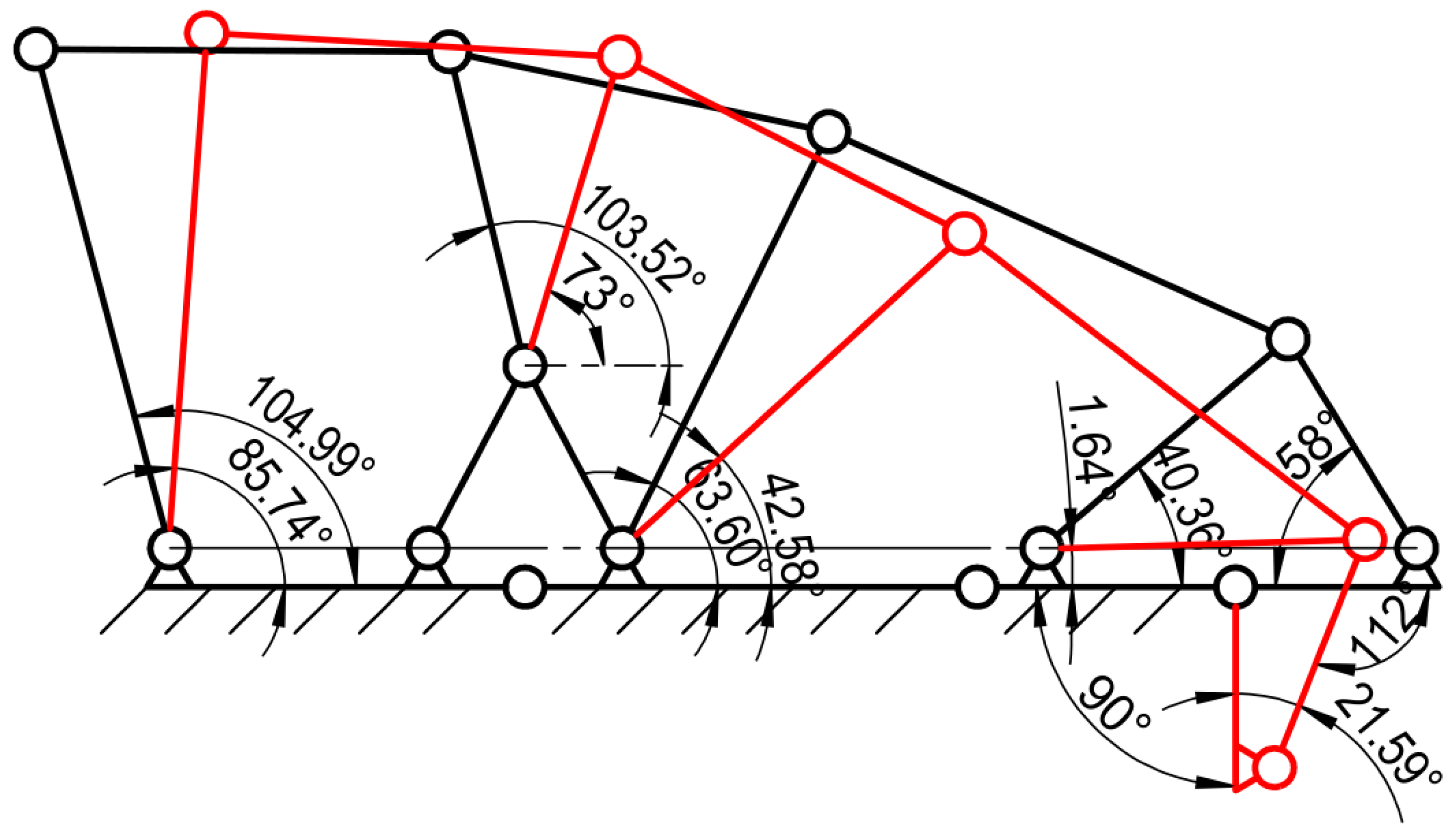
We then calculated the correction vector from A ( i ) Δ ϕ = f ( i ) . This is iterated, and a solution is obtained if it is within the allowed values. In this study, we allowed the initial member lengths as follows: l1 = 40 mm, l2 = 32 mm, l3 = 25 mm, l4 = 16 mm, l5 = 16 mm, l6 = 30 mm, l7 = 36 mm, l8 = 39 mm, l9 = 25 mm, l10 = 35 mm, l11 = 19 mm, l12 = 14 mm, and l13 = 20 mm. We used reverse projection to ensure that the end joint was in the best position for analysis, (i.e., ϕ 10 was used as a polar coordinate in the actual solution, and q was used as the object of the solution to obtain the projection of the motor when the distal finger end of the hand was in a definite position). Table 2 presents the solution results. Figure 25 shows the specific postures of the members.

4.4. Kinetic Analysis

We analyzed the kinetics by using Adams simulation 2020 software. The mechanism was first modeled by using the 3D computer-aided design software SolidWorks 2022. The model was saved in .x_t format and was imported into Adams so that we could add constraints, kinematic subsets, and moments.
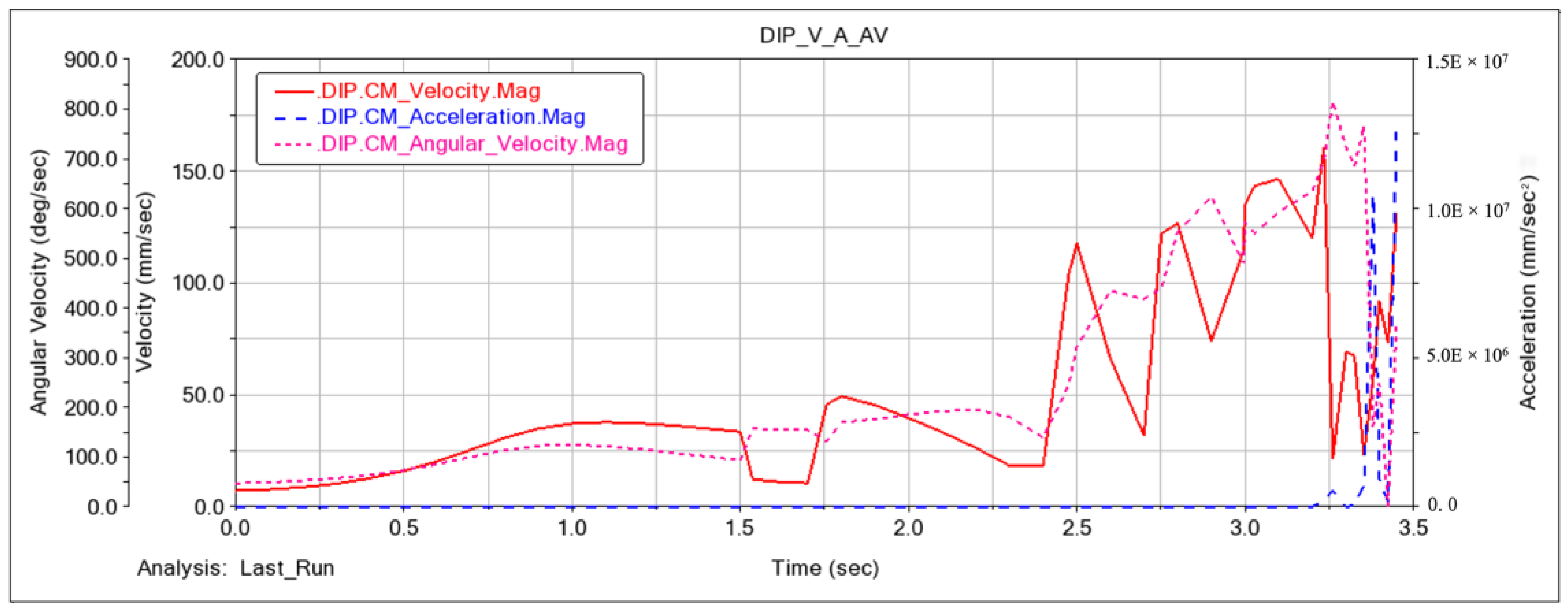
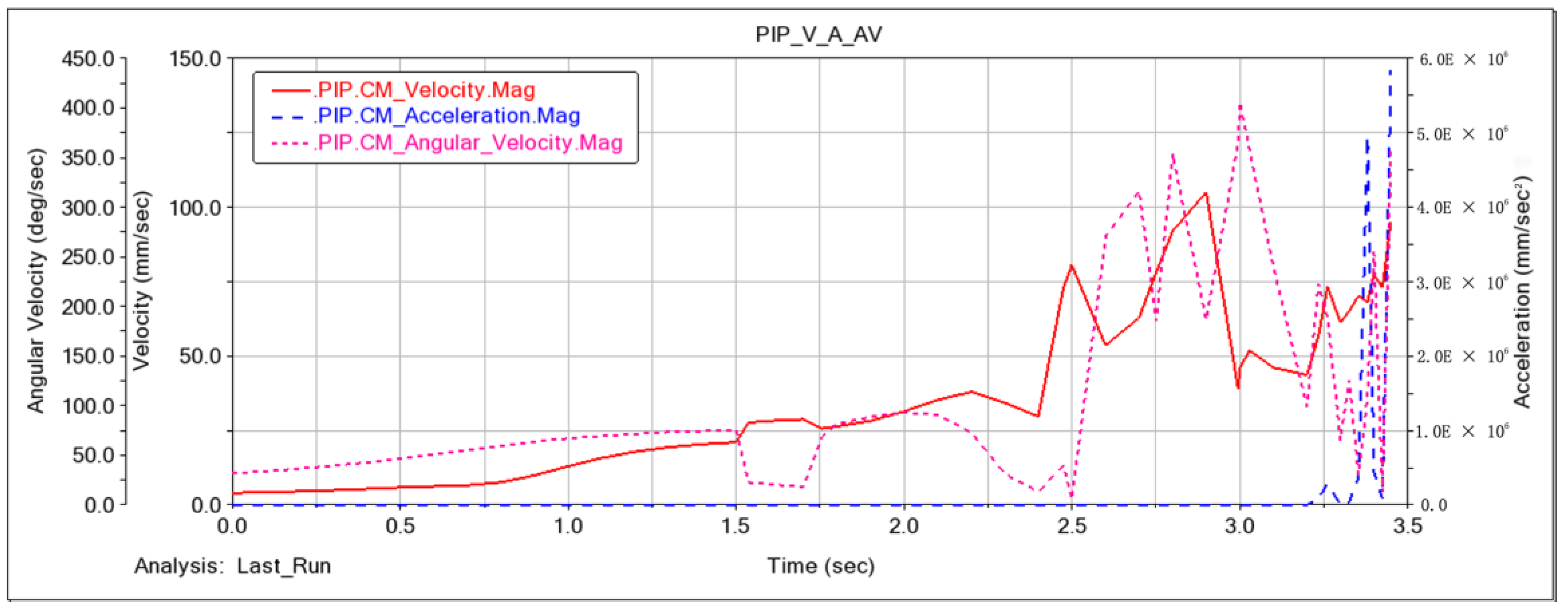
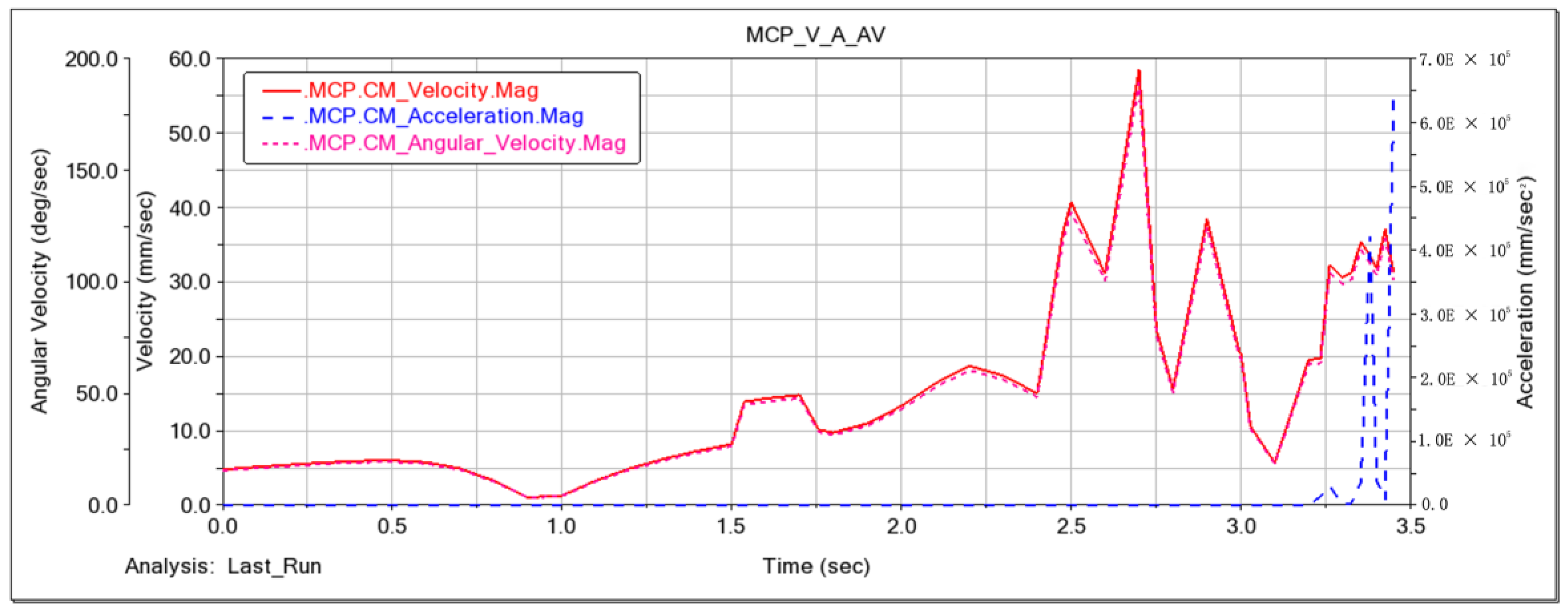
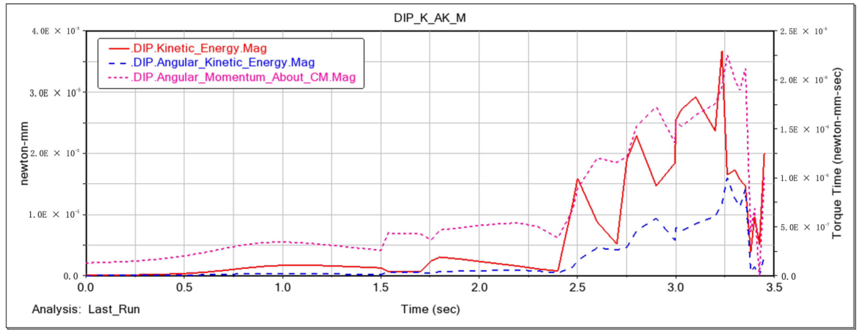
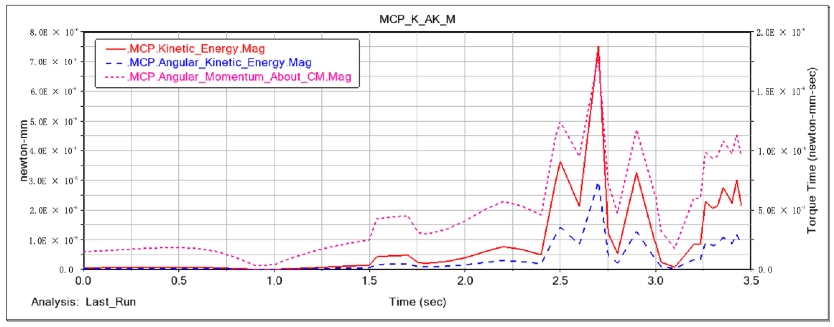
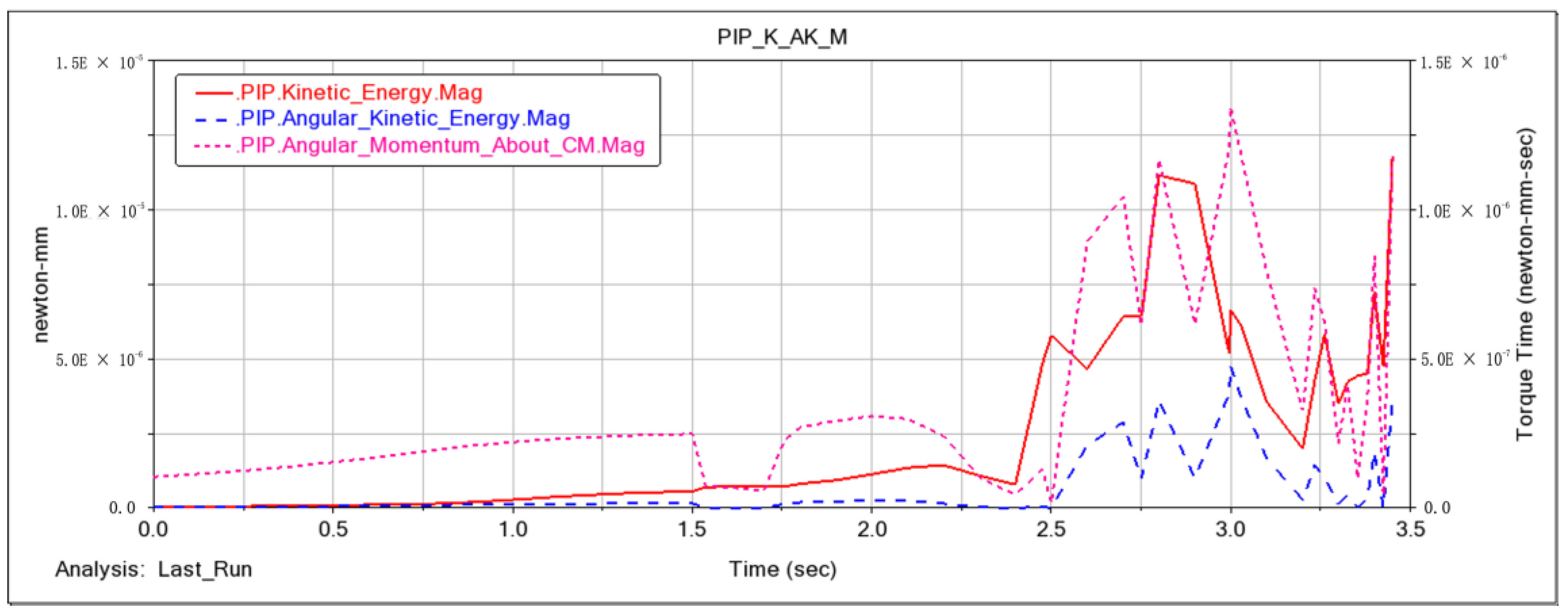
We then checked the simulation model in terms of the Gruber count and the numbers of movable components, kinematic subsets, constraints, and moments to ensure correct simulation. Figure 26, Figure 27 and Figure 28 depict the analysis of the velocity, acceleration, and angular velocity of the exoskeleton mechanism at the MCP/PIP and DIP joints. After 1.5–2 s, the natural flexion and extension range of the fingers is completed. Subsequently, there are abnormal movements, indicating a motion problem in the underactuated structure, especially in the later stages of motion. There is a noticeable fluctuation in angular velocity, and the angular acceleration reaches significant values, leading to a situation where the mechanism becomes unsolvable. Nevertheless, even with these challenges, within the normal range of motion, especially when the exoskeleton is worn, the overall operation of the mechanism remains within an acceptable range due to constraints imposed by the human finger. Figure 29, Figure 30 and Figure 31 present the torque, angular momentum, and momentum analysis for the MCP/PIP and DIP joints of the exoskeleton mechanism, consistent with the aforementioned analysis, further confirming the effectiveness of the exoskeleton mechanism within the natural range of finger motion. However, the data showed some spikes, which indicate a stutter in the movement of the structure. We can optimize the dimensions of the connecting members to make the movement smoother.

5. Discussion

Because of the information asymmetry between designers and users, a unified platform for modular product design is essential. Based on a systematic analysis of the advantages and disadvantages of existing functional structural design models, we have developed the RFWBS model with a hierarchical structure correlating the user requirements, functions, principles, behaviors, and structure of a complex product. The proposed model provides effective technical support for the hybrid mapping of solutions into the design of neurorehabilitation physiotherapy equipment. The proposed model provides a hierarchical iterative design process for the development of rehabilitation equipment. In contrast to the conventional FBS model, the proposed RFWBS model incorporates user requirements and principle workspace constraints, which makes the modeling process more rational, allows multilevel mapping of innovative solutions, and establishes a scientifically sound support platform for product design.
This paper applies the RFWBS model to the design process of neurorehabilitation therapy equipment and compares it with existing models. The selected models for comparison include the FBS model, Situated FBS model, RFBS model, and FCBS model. The table summarizes detailed information about the comparison.
In terms of model description, an analysis and comparison of the objects and emphases of each model was conducted to identify differences. Most of these models either focus on describing design objects or are used to describe the design process. The FBS model emphasizes clarifying relationships between design objects; the Situated FBS model emphasizes the transformation of design knowledge; the RFBS model, based on FBS, attempts to integrate with SysML, focusing on the driving and integration of design models; the FCBS model seeks a complementary combination of functional and case modeling. Compared to the aforementioned models, the RFWBS model emphasizes integrated representation, aiming to address the multi-level mixed mapping of design knowledge. It not only identifies design objects and their relationships but also considers the principle knowledge involved in the entire design process, making it a more objective design model. Secondly, the RFWBS model takes a dynamic perspective on design knowledge, emphasizing the evolution of design knowledge across the entire design project or different projects to better meet the diversity of designers’ knowledge needs. It is a novel expression and solution technology for product design knowledge.
Previous models did not provide a method for capturing design knowledge through the design iteration process. The RFWBS model offers a systematic framework for constructing organized design knowledge. The RFWBS model, in particular, focuses on the dynamic evolution of design, involving requirements analysis and the reuse of principle knowledge based on existing designs. Therefore, it can capture useful knowledge about specific issues considered in the design, existing solutions, the relationships between requirements, and the construction of new solutions.

6. Conclusions

Product design is a process of meeting user requirements that involves a number of mapping mechanisms and reasoning stages. We applied the proposed RFWBS model to map user requirements, functions, the principle workspace, behaviors, and the structure for the design of neurorehabilitation physiotherapy equipment. The RFWBS model establishes a multilayer process of combination and optimization to obtain a design solution that meets user requirements. We applied the proposed model to design a neurorehabilitation robotic glove and verified the rationality of the structure through kinematic analysis. The RFWBS model is multifaceted and hierarchical to enable innovative design on multiple levels for functional decoupling and functional structure matching. The dynamic solution mechanism reflects the iterative nature of the design process and provides new research ideas for the design of neurorehabilitation physiotherapy equipment. In this study, we validated the proposed model by applying it to a neurorehabilitation robotic glove as an example.
Certainly, this research also has certain limitations, manifested in the following three aspects:
(1)
The research focus of this project tends to analyze, summarize, and generalize the design procedures and methods of structure–function mapping, aiming to enhance and improve primarily in the field of human–machine integration. However, there is limited coverage of the control system for neurorehabilitation robotic gloves and the design methods for human–machine interaction.
(2)
To establish a systematic modular design method based on RFWBS for neurorehabilitation therapy devices, this paper takes a rehabilitation robotic glove as an example to verify the established design and modeling methods. However, it is necessary to apply this method to other mechanical systems continuously, aiming to refine and enrich the modular design method of RFWBS.
(3)
Through simulation analysis, it is found that the hand exoskeleton structure needs to be worn to restrict the workspace, enabling the exoskeleton structure to have good kinematic and dynamic performance. However, when the exoskeleton structure moves independently, due to under-actuation, there are significant angular velocity fluctuations when joint movements exceed the natural range of motion, affecting the overall performance of the mechanism. In future work, we will build a prototype of the structure, conduct performance testing, optimize the structure based on experimental data, and then complete the work related to the verification and comparison of the issues mentioned above. In future designs, we will focus on applying the RFWBS model to the physical prototype to enhance the human–machine interaction, comfort, and safety of the prototype.

Author Contributions

Conceptualization, N.J.; Methodology, P.Z.; Software, J.Y.; Investigation, X.H.; Writing—original draft, N.J.; Supervision, K.Y.L. All authors have read and agreed to the published version of the manuscript.

Funding

This research received no external funding.

Data Availability Statement

Data is not available due to privacy or ethical constraints.

Conflicts of Interest

The authors declare no conflict of interest.

Abbreviations

CPMContinuous passive motion
FBSFunction–behavior–structure
MCPMetacarpophalangeal
IPInterphalangeal
DIPDistal interphalangeal

References

  1. Aisen, M.L.; Kerkovich, D.; Mast, J.; Mulroy, S.; AL Wren, T.; Kay, R.M.; Rethlefsen, S.A. Cerebral palsy: Clinical care and neurological rehabilitation. Lancet Neurol. 2011, 10, 844–852. [Google Scholar] [CrossRef]
  2. Young, J.A.; Tolentino, M. Neuroplasticity and Its Applications for Rehabilitation. Am. J. Ther. 2011, 18, 70–80. [Google Scholar] [CrossRef] [PubMed]
  3. Xing, Y.; Bai, Y. A Review of Exercise-Induced Neuroplasticity in Ischemic Stroke: Pathology and Mechanisms. Mol. Neurobiol. 2020, 57, 4218–4231. [Google Scholar] [CrossRef] [PubMed]
  4. Rossini, P.M.; Calautti, C.; Pauri, F.; Baron, J.-C. Post-stroke plastic reorganisation in the adult brain. Lancet Neurol. 2003, 2, 493–502. [Google Scholar] [CrossRef] [PubMed]
  5. Lynch, D.; Ferraro, M.; Krol, J.; Trudell, C.M.; Christos, P.; Volpe, B.T. Continuous passive motion improves shoulder joint integrity following stroke. Clin. Rehabil. 2005, 19, 594–599. [Google Scholar] [CrossRef] [PubMed]
  6. Stefanova, I. Effects of using continuous passive motion device in the rehabilitation upper limb following stroke. In Proceedings of the EIIC—2nd Electronic International Interdisciplinary Conference, Zilina, Slovakia, 8–12 August 2016; pp. 240–242. [Google Scholar] [CrossRef]
  7. Volpe, B.T.; Ferraro, M.; Lynch, D.; Christos, P.; Krol, J.; Trudell, C.; Krebs, H.I.; Hogan, N. Robotics and other devices in the treatment of patients recovering from stroke. Curr. Atheroscler. Rep. 2004, 6, 314–319. [Google Scholar] [CrossRef] [PubMed]
  8. Zheng, Q.-X.; Ge, L.; Wang, C.C.; Ma, Q.-S.; Liao, Y.-T.; Huang, P.-P.; Wang, G.-D.; Xie, Q.-L.; Rask, M. Robot-assisted therapy for balance function rehabilitation after stroke: A systematic review and meta-analysis. Int. J. Nurs. Stud. 2019, 95, 7–18. [Google Scholar] [CrossRef]
  9. Singh, N.; Saini, M.; Kumar, N.; Srivastava, M.V.P.; Mehndiratta, A. Evidence of neuroplasticity with robotic hand exoskeleton for post-stroke rehabilitation: A randomized controlled trial. J. Neuroeng. Rehabil. 2021, 18, 76. [Google Scholar] [CrossRef]
  10. Tefertiller, C.; Pharo, B.; Evans, N.; Winchester, P. Efficacy of rehabilitation robotics for walking training in neurological disorders: A review. J. Rehabil. Res. Dev. 2011, 48, 387–416. [Google Scholar] [CrossRef]
  11. Lamé, G.; Yannou, B.; Cluzel, F. Usage-driven problem design for radical innovation in healthcare. BMJ Innov. 2018, 4, 15–23. [Google Scholar] [CrossRef]
  12. Chandrasegaran, S.K.; Ramani, K.; Sriram, R.D.; Horváth, I.; Bernard, A.; Harik, R.F.; Gao, W. The evolution, challenges, and future of knowledge representation in product design systems. Comput. Des. 2013, 45, 204–228. [Google Scholar] [CrossRef]
  13. Tang, D.; Zhu, R.; Tang, J.; Xu, R.; He, R. Product design knowledge management based on design structure matrix. Adv. Eng. Inform. 2010, 24, 159–166. [Google Scholar] [CrossRef]
  14. Galle, P. The ontology of Gero’s FBS model of designing. Des. Stud. 2009, 30, 321–339. [Google Scholar] [CrossRef]
  15. Vermaas, P.E.; Dorst, K. On the conceptual framework of John Gero’s FBS-model and the prescriptive aims of design methodology. Des. Stud. 2007, 28, 133–157. [Google Scholar] [CrossRef]
  16. Cascini, G.; Fantoni, G.; Montagna, F. Situating needs and requirements in the FBS framework. Des. Stud. 2013, 34, 636–662. [Google Scholar] [CrossRef]
  17. Gero, J.S.; Kannengiesser, U. The situated function–behaviour–structure framework. Des. Stud. 2004, 25, 373–391. [Google Scholar] [CrossRef]
  18. Christophe, F.; Bernard, A.; Coatanéa, E. RFBS: A model for knowledge representation of conceptual design. CIRP Ann. 2010, 59, 155–158. [Google Scholar] [CrossRef]
  19. Gu, C.-C.; Hu, J.; Peng, Y.-H.; Li, S. FCBS model for functional knowledge representation in conceptual design. J. Eng. Des. 2012, 23, 577–596. [Google Scholar] [CrossRef]
  20. Li, S. A matrix-based clustering approach for the decomposition of design problems. Res. Eng. Des. 2011, 22, 263–278. [Google Scholar] [CrossRef]
  21. Fan, B.; Qi, G.; Hu, X.; Yu, T. A network methodology for structure-oriented modular product platform planning. J. Intell. Manuf. 2015, 26, 553–570. [Google Scholar] [CrossRef]
  22. Chen, Y.; Zhao, M.; Xie, Y.; Zhang, Z. A new model of conceptual design based on Scientific Ontology and intentionality theory. Part II: The process model. Des. Stud. 2015, 38, 139–160. [Google Scholar] [CrossRef]
  23. Yannou, B.; Cluzel, F.; Lamé, G. Draft: Adapting the FBS model of designing for usage-driven innovation processes. In International Design Engineering Technical Conferences and Computers and Information in Engineering Conference; American Society of Mechanical Engineers: New York, NY, USA, 2018; p. 10. [Google Scholar]
  24. Qin, H.; Wang, H.; Johnson, A.L. A RFBSE model for capturing engineers’ useful knowledge and experience during the design process. Robot. Comput. Manuf. 2017, 44, 30–43. [Google Scholar] [CrossRef]
  25. Wang, Z.; Zheng, P.; Lee, C.-H.; Chen, C.-H. Knowledge Representation and Reasoning Methods in the Concept Develop-ment of Product Design: A State-of-the-Art Review. In Transdisciplinary Engineering Methods for Social Innovation of Industry; IOS Press: Amsterdam, The Netherlands, 2018; pp. 478–487. [Google Scholar]
  26. Yuan, L.; Liu, Y.; Sun, Z.; Cao, Y.; Qamar, A. A hybrid approach for the automation of functional decomposition in conceptual design. J. Eng. Des. 2016, 27, 333–360. [Google Scholar] [CrossRef]
  27. Umeda, Y.; Tomiyama, T. FBS Modeling: Modeling Scheme of Function for Conceptual Design. In Proceedings of the 9th International Workshop on Qualitative Reasoning, Amsterdam, The Netherlands, 16–19 May 1995; p. 8. [Google Scholar]
  28. Chakrabarti, A.; Bligh, T.P. A scheme for functional reasoning in conceptual design. Des. Stud. 2001, 22, 493–517. [Google Scholar] [CrossRef]
  29. Chen, B.; Xie, Y. Functional knowledge integration of the design process. Sci. China Technol. Sci. 2017, 60, 209–218. [Google Scholar] [CrossRef]
  30. Wu, C.; Chen, T.; Li, Z.; Liu, W. A function-oriented optimising approach for smart product service systems at the conceptual design stage: A perspective from the digital twin framework. J. Clean. Prod. 2021, 297, 126597. [Google Scholar] [CrossRef]
  31. Price, C.J.; Friston, K.J. Functional ontologies for cognition: The systematic definition of structure and function. Cogn. Neuropsychol. 2005, 22, 262–275. [Google Scholar] [CrossRef]
  32. Wynn, D.; Clarkson, J. Models of designing. In Design Process Improvement; Clarkson, J., Eckert, C., Eds.; Springer: London, UK, 2005; pp. 34–59. [Google Scholar] [CrossRef]
  33. Gui, J.-K.; Mäntylä, M. Functional understanding of assembly modelling. Comput. Des. 1994, 26, 435–451. [Google Scholar] [CrossRef]
  34. Nomaguchi, Y.; Fujita, K. Knowledge representation framework for interactive capture and management of reflection process in product concepts development. Adv. Eng. Inform. 2013, 27, 537–554. [Google Scholar] [CrossRef]
  35. Wang, Z.; Cui, L.; Guo, W.; Zhao, L.; Yuan, X.; Gu, X.; Tang, W.; Bu, L.; Huang, W. A design method for an intelligent manufacturing and service system for rehabilitation assistive devices and special groups. Adv. Eng. Inform. 2022, 51, 101504. [Google Scholar] [CrossRef]
Figure 1. Neuroplasticity theory.
Machines 12 00043 g001
Figure 2. FBS model mapping.
Machines 12 00043 g002
Figure 3. Function–structure mapping strategy.
Machines 12 00043 g003
Figure 4. Modular product design system.
Machines 12 00043 g004
Figure 5. Knowledge system framework for product design.
Machines 12 00043 g005
Figure 6. Cyclic mapping of the proposed RFWBS model.
Machines 12 00043 g006
Figure 7. User requirements module.
Machines 12 00043 g007
Figure 8. Workflow from acquisition of user requirements to obtaining of structural solution for product.
Machines 12 00043 g008
Figure 9. Functional innovation module.
Machines 12 00043 g009
Figure 10. Principle workspace module.
Machines 12 00043 g010
Figure 11. Decoupling of principle workspace module.
Machines 12 00043 g011
Figure 12. Diagram of structural module solver.
Machines 12 00043 g012
Figure 13. RFWBS ontology-based model.
Machines 12 00043 g013
Figure 14. Principle workspace module of the neurorehabilitation manipulator.
Machines 12 00043 g014
Figure 15. Schematic diagram of the four-finger drive mechanism.
Machines 12 00043 g015
Figure 16. Schematic diagram of the thumb-drive mechanism.
Machines 12 00043 g016
Figure 17. Mapping solution of the RFWBS model for the neurorehabilitation manipulator.
Machines 12 00043 g017
Figure 18. Structural design solution for the neurorehabilitation manipulator.
Machines 12 00043 g018
Figure 19. Diagram matching the neurorehabilitation robotic glove to the upper limb.
Machines 12 00043 g019
Figure 20. Rendering of wearable neurorehabilitation manipulator.
Machines 12 00043 g020
Figure 21. Final rendering.
Machines 12 00043 g021
Figure 22. Detailed view of the internal structure.
Machines 12 00043 g022
Figure 23. Simplified mechanism of the neurorehabilitation robotic glove on a Lagrangian coordinate system.
Machines 12 00043 g023
Figure 24. Schematic diagram of the movement mechanism.
Machines 12 00043 g024
Figure 25. Specific postures of members based on solution.
Machines 12 00043 g025
Figure 26. Velocity, acceleration, and angular velocity of the DIP joint.
Machines 12 00043 g026
Figure 27. Velocity, acceleration, and angular velocity of the PIP joint.
Machines 12 00043 g027
Figure 28. Velocity, acceleration, and angular velocity of the MCP joint.
Machines 12 00043 g028
Figure 29. Momentum, angular momentum, and torque of the DIP joint.
Machines 12 00043 g029
Figure 30. Momentum, angular momentum, and torque of the PIP joint.
Machines 12 00043 g030
Figure 31. Momentum, angular momentum, and torque of the MCP joint.
Machines 12 00043 g031
Table 1. Solution results.
Dimension of User RequirementsNumbersUser Requirements
Basic RequirementsR1Safety and Stability
R2Neurorehabilitation
R3Precise Human–Machine Interaction
R4Comfortable Use
Auxiliary RequirementsR5Ease of Wear
R6Assisted Rehabilitation
R7Aesthetic Design
R8Personalized Requirements
Table 2. Solution results.
ϕ 10 Number of Iterationsq f i Δ ϕ
0 (0°)11.7710 (101.47°)0.0552−0.0412
21.8104 (103.73°)0.0031−0.0003
31.8324 (104.99°)3 × 10⁻⁸ −2 × 10⁻⁷
1.5708 (90°)11.4375 (82.36°)−0.0376−0.0125
21.4694 (84.19°)0.0002−0.0001
31.4964 (85.74°)−1 × 10⁻⁸−1 × 10⁻⁷
Disclaimer/Publisher’s Note: The statements, opinions and data contained in all publications are solely those of the individual author(s) and contributor(s) and not of MDPI and/or the editor(s). MDPI and/or the editor(s) disclaim responsibility for any injury to people or property resulting from any ideas, methods, instructions or products referred to in the content.