Article

Evaluation of Machining Variables on Machinability of Nickel Alloy Inconel 718 Using Coated Carbide Tools

by
Muhammad Iftikhar Faraz
1,* and
Jana Petru
2
1
Department of Mechanical Engineering, College of Engineering, King Faisal University, Al-Ahsa 31982, Saudi Arabia
2
Department of Machining, Assembly and Engineering Metrology, Mechanical Engineering Faculty, VŠB-Technical University of Ostrava, 17, Listopadu 2172/15, 708 00 Ostrava, Czech Republic
*
Author to whom correspondence should be addressed.
Machines 2024, 12(1), 4; https://doi.org/10.3390/machines12010004
Submission received: 26 November 2023 / Revised: 13 December 2023 / Accepted: 18 December 2023 / Published: 20 December 2023
(This article belongs to the Special Issue Sustainable Manufacturing and Green Processing Methods)

Abstract

:
The current work was undertaken with the research aim of experimental examination of tool wear, surface roughness and burr formation during the micro-milling of Inconel 718 using different coated tools. Inconel 718 is one of the most widely used materials for purpose-oriented utilization owing to its preferred mechanical and physical properties, including high strength and corrosion resistance. On the opposite end, the machining of Inconel 718 poses certain machinability challenges, which significantly elevates tool wear and subsequently surface roughness. Cutting speed, feed rate and depth of cut were selected as variable machining inputs. With reference to tool wear, all input variables were found to be significant, with tool coating having the highest contribution ratio of 36.19%. In case of surface roughness, cutting speed and tool coating were identified as effective input parameters with contribution ratios of 51.24% and 34.27%, respectively. Similarly, depth of cut proved to be an influential factor for burr height formation (in both up-milling and down-milling), whereas feed rate had the highest contribution ratios for burr width formation during up-milling and down-milling, i.e., 39.28% and 36.26%, respectively. Consequently, contour plots for output responses were drawn between significant parameters to analyze machinability. One of the vital research outcomes was the identification of a tool coating parameter that is significant for all four analyzed aspects of burr formation. In addition, regression equations were formulated for machining responses. The best- and worst-case scenarios for individual input parameters, as identified from main effects plots, were validated during confirmatory experimentation. Moreover, effects of input variables on output response were characterized using close-up imagery, and dominant wear mechanisms were also identified. The utility of the research is underlined by the optimization of the sustainability and productivity of the manufacturing process.

1. Introduction

The rapid advancement of the technology of new production methods and materials has caused the swift progress of aviation sector in the last few decades. A prominent example is the redesigning of aircraft engines to be more lightweight as well as efficient with fuel expenses. One of the preferred materials worldwide, Inconel 718, has been extensively used because of its properties like corrosion resistance and high strength. Inconel 718 is extremely resistant to wear and corrosion owing to its composition of nickel, chromium and iron in addition to other elements. It is used to create blades, disks and other parts of aircraft engines [1,2,3]. Its corrosion resistance, high strength and high temperature creep resistance have also found utility in the manufacture of various components other than aviation engines. Various parts for gas turbines and rockets are also manufactured using Inconel 718. Electrochemical micromachining has also proved to be a productive manufacturing process using Inconel 718. Additionally, Inconel 718 can be drilled using electrochemical machining for the manufacture of various micro-products. Nevertheless, the micromachining of Inconel 718 poses a challenge [4,5,6,7] due to its poor machinability. Resultantly, research is underway using various combinations of input variables to arrive at optimum machining conditions. Industrial component miniaturization with acceptable dimensional accuracy and a variety of functionalities is a widespread avenue of research. Using micromachining technology, small parts and components can be produced in large quantities. The technical definition of micromachining can be expressed in a variety of ways. This material removal technique produces tiny and accurate 3D objects with sizes between 1 nm and 0.99 nm [8,9,10]. Micro parts and components of all kinds have experienced a sharp rise in demand in recent years including for pharmaceutical micro pump delivery systems and inkjet print heads. The production of small parts necessitates precise tooling and highly reliable procedures with consistent repeatability.
Determining the rate of material removal in mechanical micromachining is a significant issue. The macro-machining industry has numerous physical and cutting mechanisms, for example, “size effect” phenomena. Due to their utilization in various industries, nickel alloys are one of the most researched materials available in the literature [11,12]. Numerous researchers have investigated various techniques for producing micro-components, including laser manufacturing, ion beam machining and ultrasonic photolithography [13,14,15,16]. A variety of aids are used, such as different coatings, coolants, machining settings and laser-assisted machining, to pre-heat and soften the Inconel 718 workpiece [17,18,19,20]. Irfan et al. [21] investigated surface roughness and tool wear at 48 m/s cutting speed while micromachining Inconel 718. TiAlN + WC/C coatings and Diamond-Like Coatings (DLC) were found to exhibit lower tool wear and optimum built-up edge (BUE). The DLC-coated tool resulted in the lowest surface roughness after AlTiN- and TiAlN + WC/C-coated tools. According to Lu et al. [22], the input parameters of cutting speed and feed rate significantly influence surface roughness. An initial increase in surface roughness was accompanied by increases in cutting length. Aslantas et al. [23] found that tool coatings had an impact on cutting force, tool wear and machining quality while micro-milling Ti6Al4V alloy. Cutting force elevated with accelerated tool wear, reducing machining precision. Ozel et al. [24] found that the cBN-coated tool outperformed the uncoated one for micro-milling Ti6Al4V in terms of surface integrity and tool wear. Aramcharoen et al. [25] investigated various tool coatings during micro-milling tool steel. Coatings like TiN were found to be superior to TiAlN in terms of flank wear and edge chipping. In addition, it was noticed that TiAlN resulted in higher burr formation than the uncoated tool. It was demonstrated that cutting speed had the highest influence on surface roughness. In the micromachining of Inconel 718, minimum quality lubrication (MQL) has been found to be more sustainable and productive than dry machining, as concluded by Rahman et al. Due to the higher cutting zone temperature and increased area of tool/workpiece contact, tool wear under dry-cut operations is significantly greater than during wet-cut operations [26,27]. Researchers have also investigated input variables with the aim of improving the quality of the machined surface during micromachining. Attanasio et al. [28] investigated the influence of burr creation, tool wear and cutting forces on the final level of machining quality in terms of surface integrity. Zhanwen et al. [29] researched surface uniformity to enhance machining quality by examining input cutting variables including feed rate and spindle speed. Moreover, Aurich et al. [30] found that changing the spindle speed and tilt angle can reduce burr formation and improve surface roughness.
Several researchers have reportedly used a variety of tool coatings to analyze various machining responses during micro-milling techniques. However, tool wear has not been comprehensively analyzed using input cutting parameters in combination with tool coatings. The need for analysis of machinability, especially at conventional and transitional cutting speed ranges, has been identified as a vital research gap and forms the basis of the current work. The research motivation for the experimental investigation is also drawn from the fact that low-speed machining systems are more economical and widely available than high-speed machines. By investigating the effects of different machining parameters on surface roughness, burr formation, and tool wear, selected as output responses, the machining process can be made more efficient, productive and sustainable at the same time.

2. Research Motivation

Micromachining is used to make products whose precision is in the order of millimeters. At this scale, it is almost impossible to post-process the product in order to ensure quality and compatibility with the design parameters. An important challenge associated with micromachined parts includes deburring and surface improvement due to small features. Since deburring and post-processing are not viable options, identifying and selecting suitable parameters which reduce the intensity of burr formation as well as produce better surface quality are vital objectives in the case of micromachining. Similarly, tool wear is also a significant aspect as it is directly related to burr formation and surface integrity. Also, concerns related to sustainability require that tool wear should be minimized through careful selection of optimum parameters so that the wastage in terms of tool replacement can be minimized. These identified issues align well with the following sustainable development goals, as chalked out by the United Nations [31,32].
Goal 9: Industry, Innovation and Infrastructure emphasizes the need to foster sustainable industrialization and innovation. Achieving this goal requires a paradigm shift towards environmentally conscious manufacturing processes. Our research delves into the realm of sustainable machining, aiming to minimize the cost of tooling and post-processes. By seeking innovative ways to promote economic manufacturing, we contribute to more efficient and eco-friendly manufacturing processes.
Goal 12: Responsible Consumption and Production underscores the importance of responsible resource utilization and waste reduction. Sustainable machining of nickel alloy Inconel 718 is inherently aligned with this goal. Lowering tool wear not only reduces the carbon footprint of machining, by economical energy consumption, but also aligns with responsible resource consumption. Additionally, by enhancing the productivity of machining through optimized and superior surface finishes, we promote efficient use of resources.

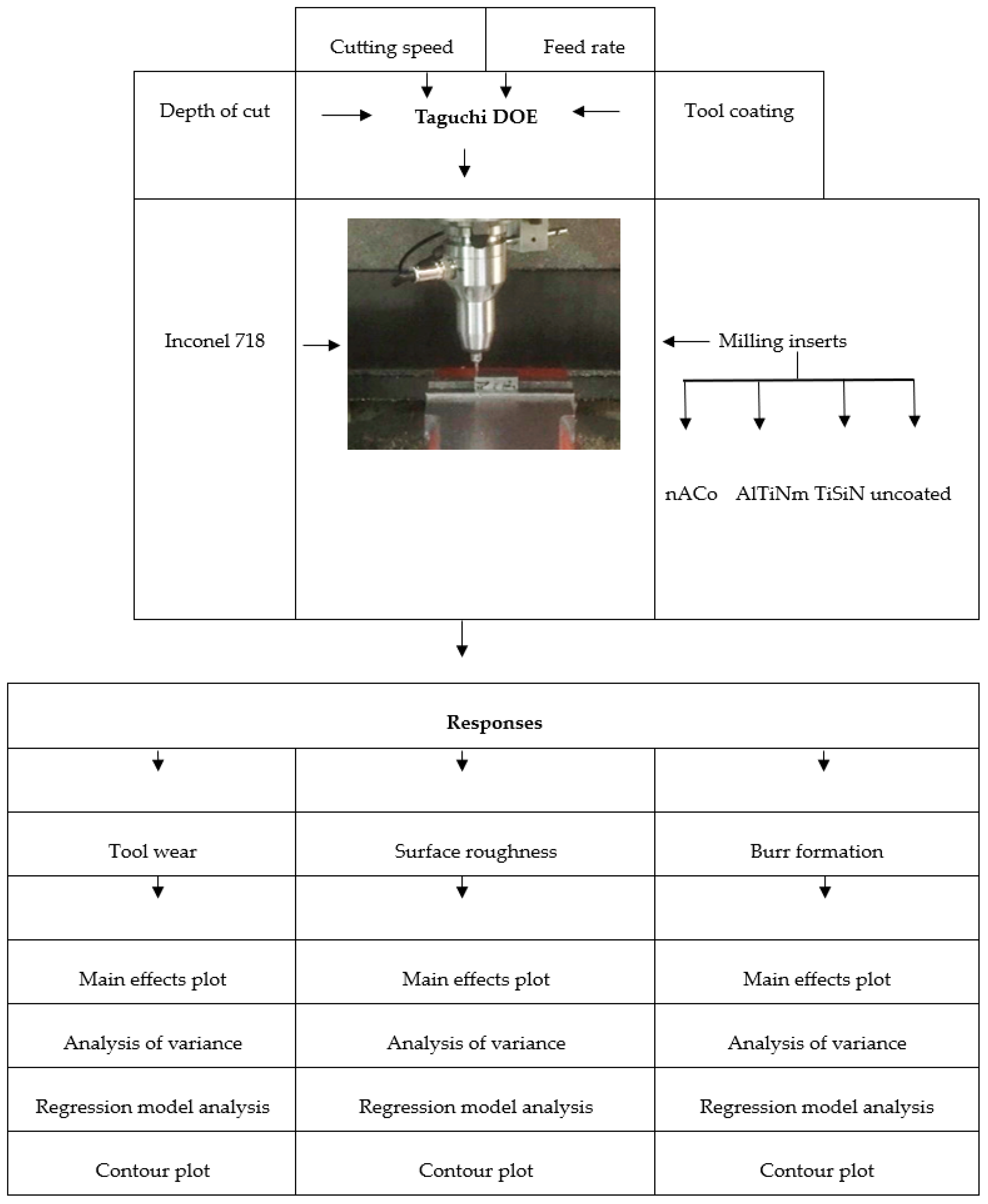
3. Experimental Procedure

A comprehensive experimental design was formulated for the milling operation. Various aspects of the experimental methodology are discussed below.

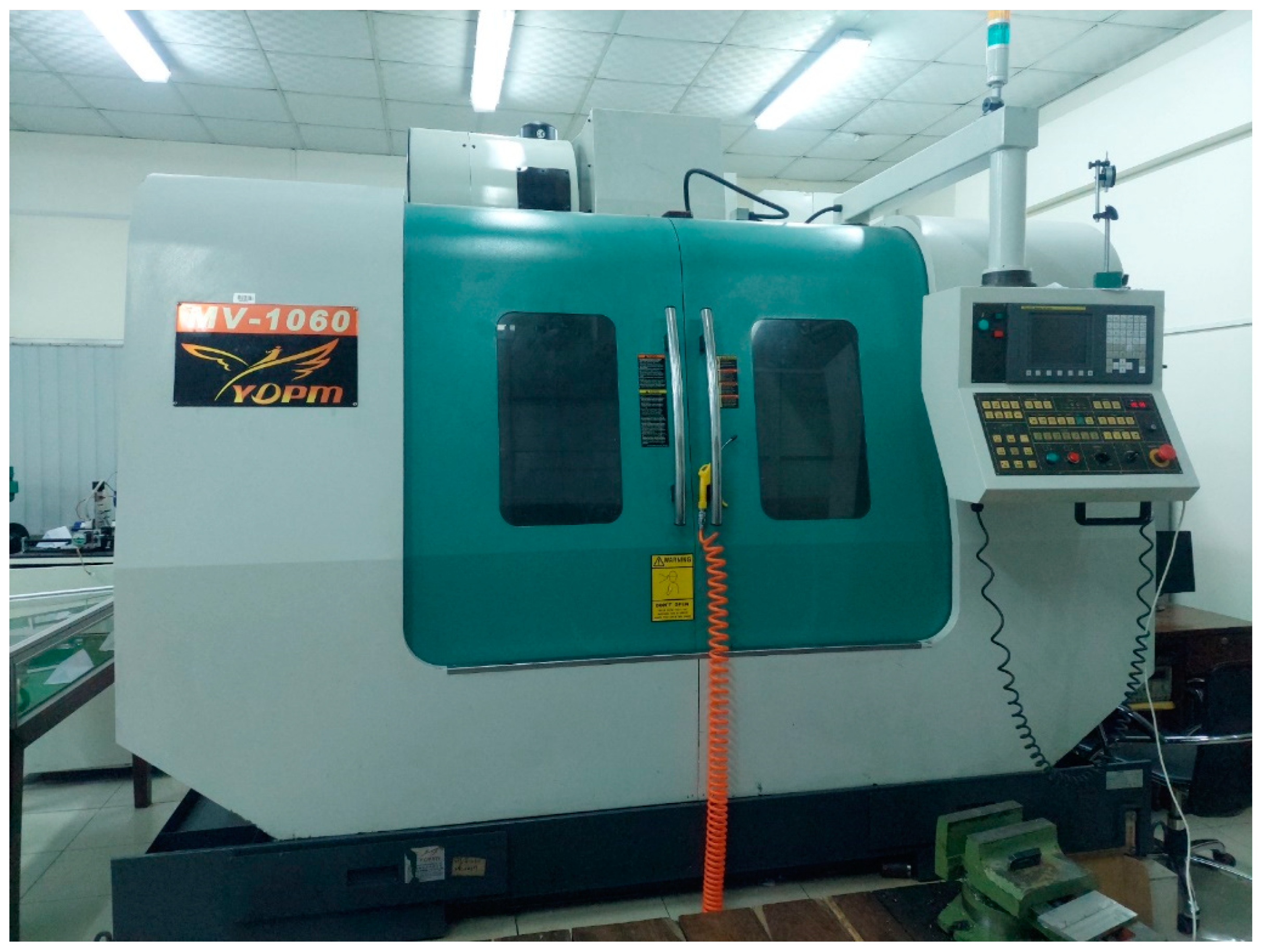
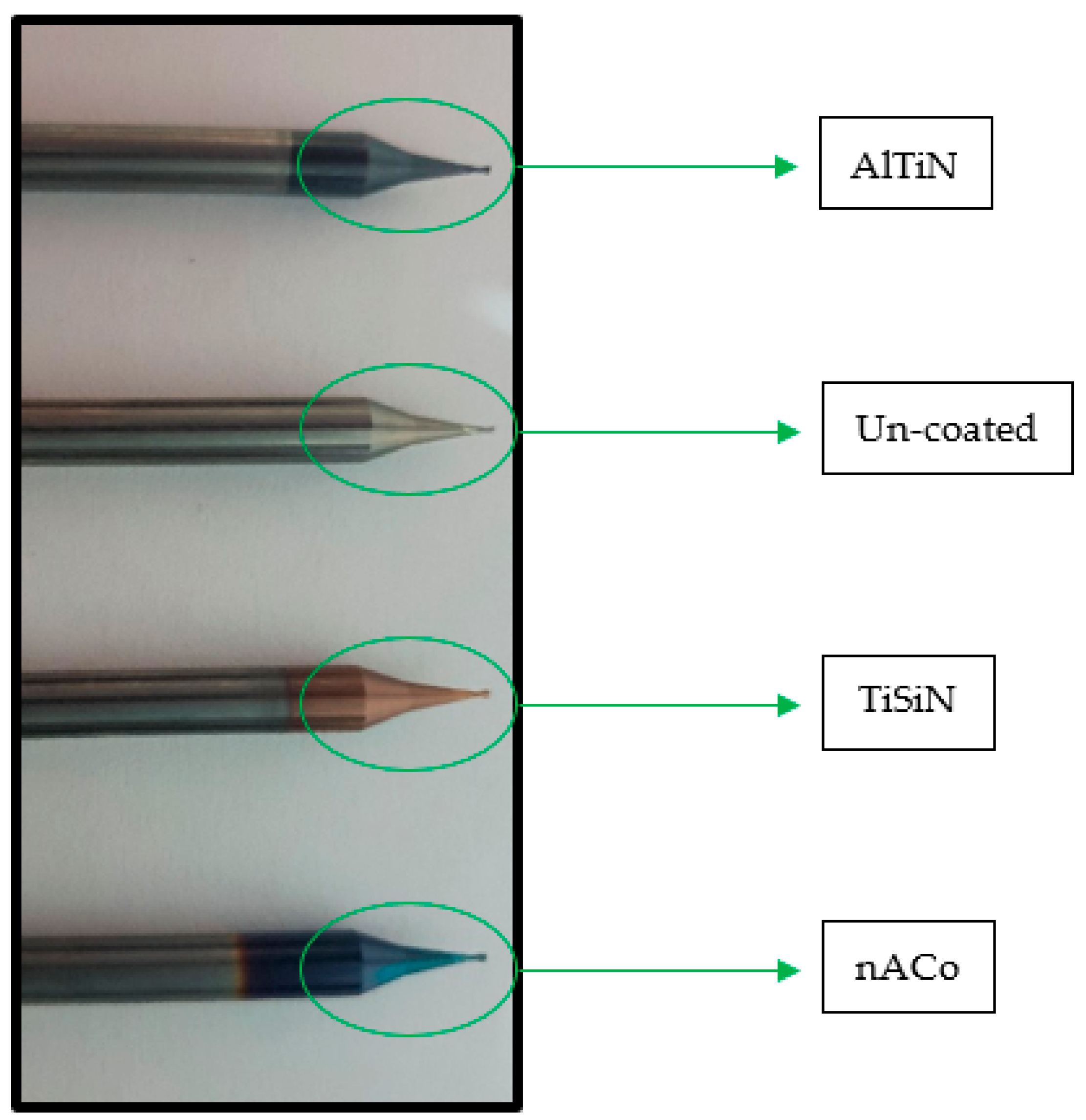
3.1. Experimental Apparatus

A CNC milling machine, as shown in Figure 1, was used for the micro-milling testing of nickel-based super alloy Inconel 718. Initially, the surface of the workpiece was leveled using a carbide end mill with a 12 mm diameter. The surface was then used as a reference point throughout the design process. To ensure precise z-axis measurements, a tool pre-setter was employed. Table 1 contains adopted test parameters. Wedge-shaped tungsten carbide cutting tools with different coatings (nACo, AlTiN, TiSiN and uncoated), as shown in Figure 2, were utilized. These tools had a diameter of 0.06 inch (0.5 mm), whereas the average cutting edge radius of micro tools with nACo-, AlTiN- and TiSiN-coated cutting edges was 1.3 mm, 1.21 mm and 3.0 mm, respectively. The milling operation was carried out in a full-immersion machining environment.
The workpiece was prepared with dimensions of 146 mm, 10 mm and 22 mm using electrical discharge machining. To minimize tool wear and tear, experiments were carried out with a 10 mm slot in the cutting length. Slot spacing was kept at 2 mm. Figure 3 displays the schematics of the milling operation, where Figure 3a shows the top view of the workpiece with intended milling pathways, and Figure 3b depicts the side view of the milling slot. The material was initially ground and polished. The waterless itching treatment from Kalling was applied for 5 s. The average grain size was found to be 23.4 µm using an Olympus DXS1000 digital microscope (Olympus Corporation, Tokyo, Japan) and ASTM standard procedure. Vickers hardness of Inconel 718 was found to be 361 HV using a Vickers micro hardness tester.

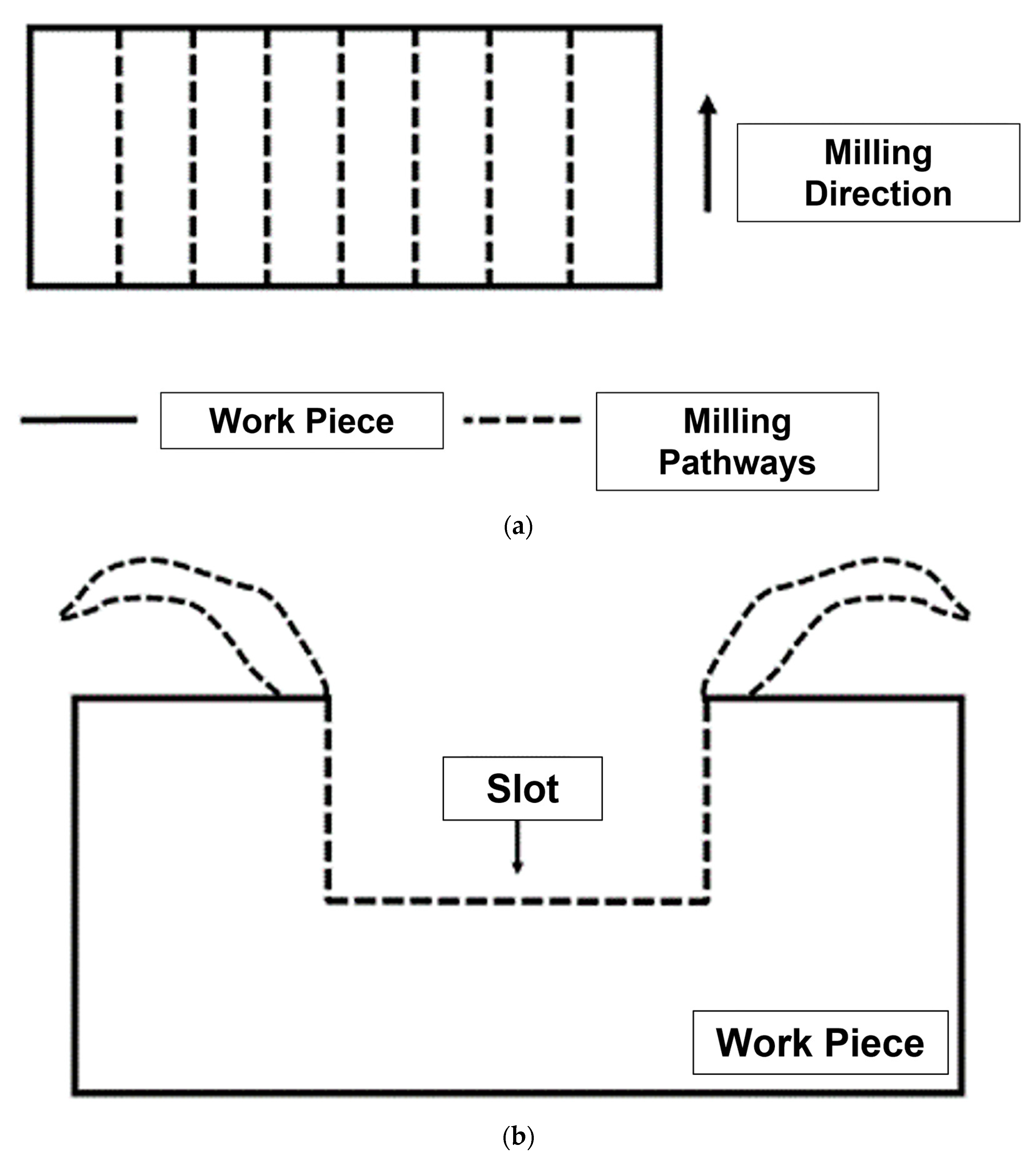
3.2. Design of Experiment

Input parameters of cutting speed (Vc), feed rate (fz), depth of cut (ap) and tool coating (tc) were selected to analyze machining responses. These input parameters were employed due to their influence on surface roughness, tool wear and burr formation [33,34,35,36]. The ranges of input parameters, as shown in Table 2, were determined from the literature [37,38]. An L16 orthogonal array was formulated based on a Taguchi design of experimentation, as shown in Table 3. A Taguchi design of experiment is a robust substitute for full factorial experimentation. It produces valid and conclusive results with a lesser number of experimental runs. Various past researchers have used it to draw meaningful conclusions, as available in the literature. Each of the sixteen experiments was run three times to ensure repeatability [39]. A new insert was used for each of the 48 experimental sets. This was necessary to determine the specific tool wear corresponding to each set of machining combinations.

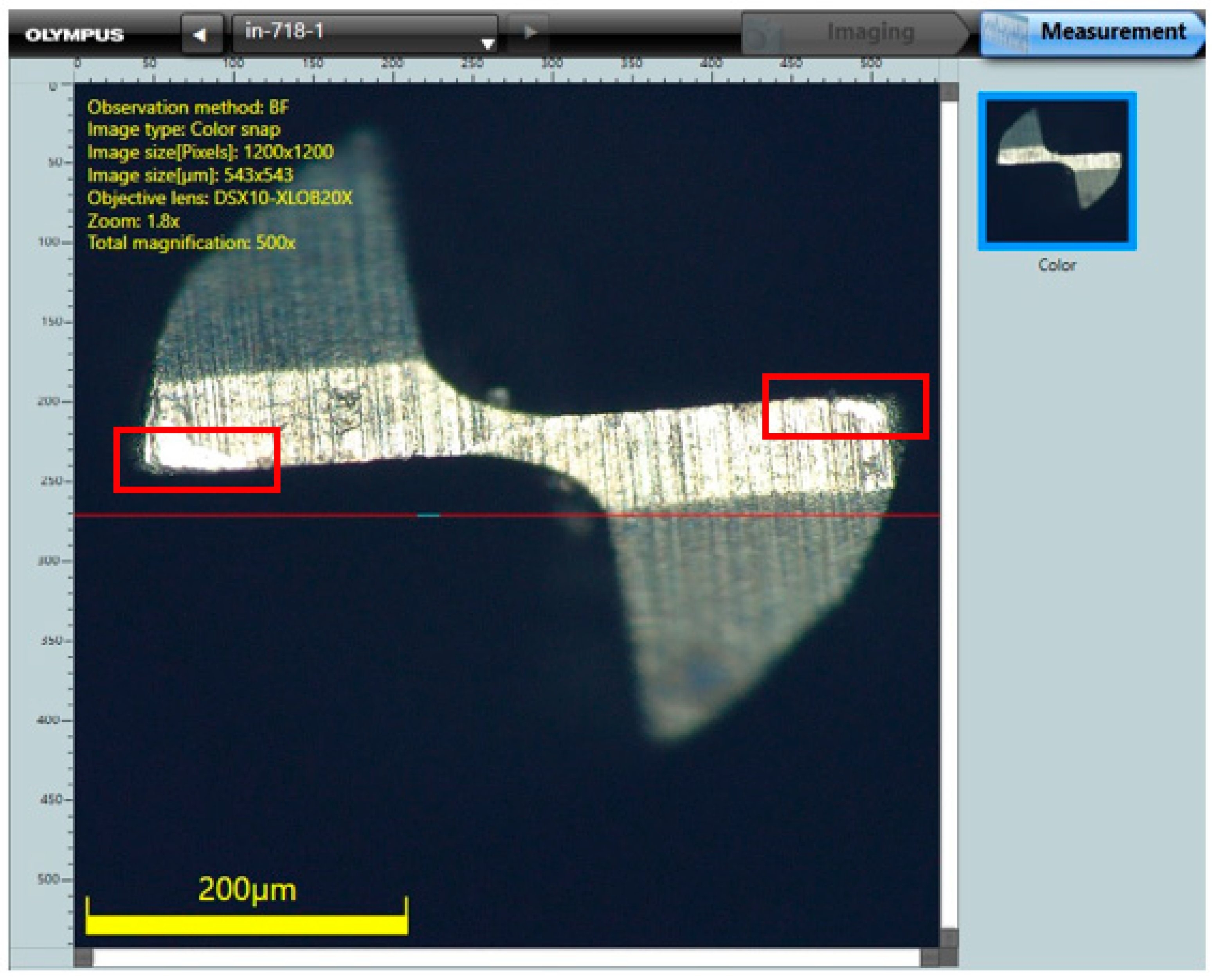
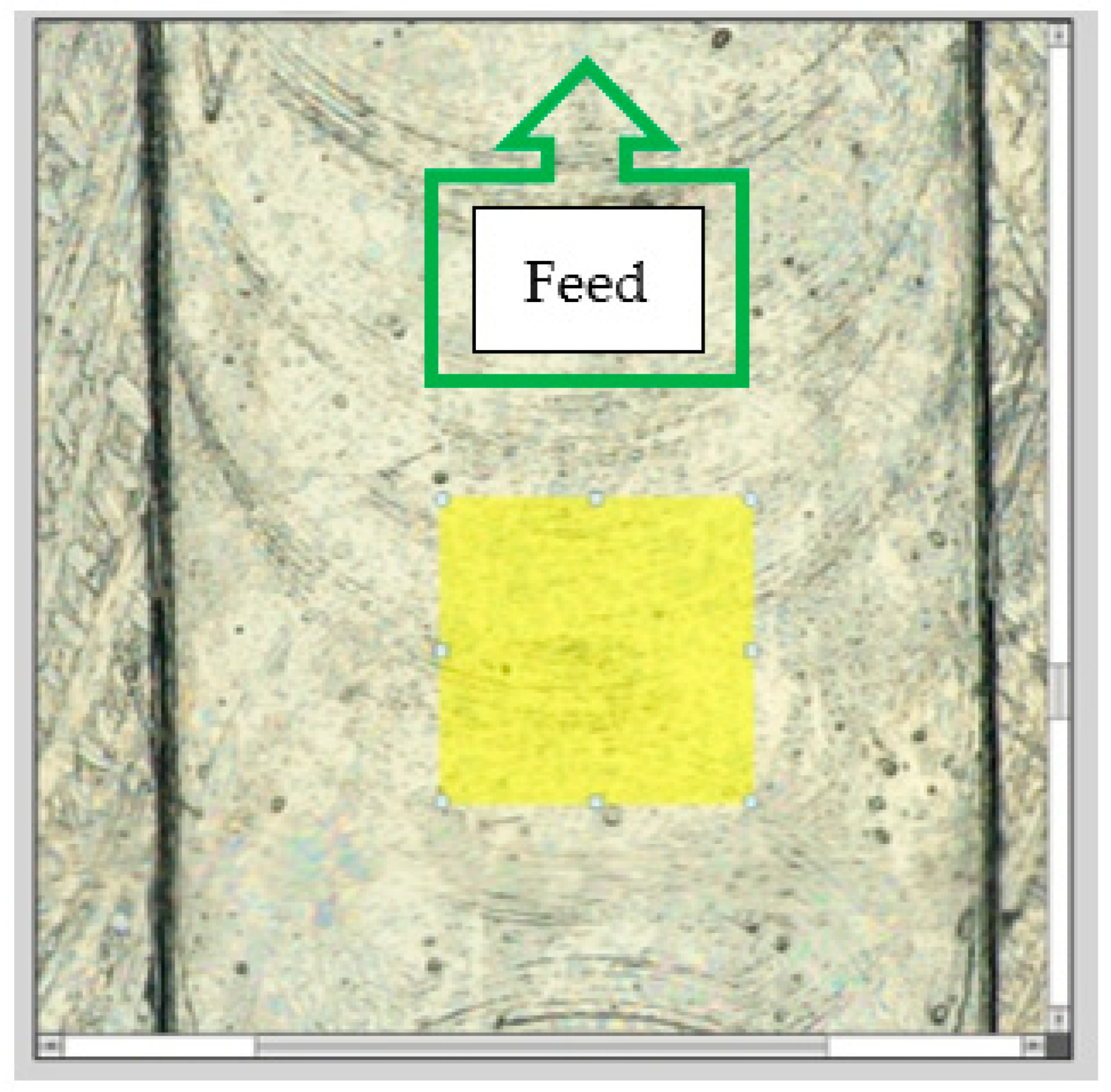
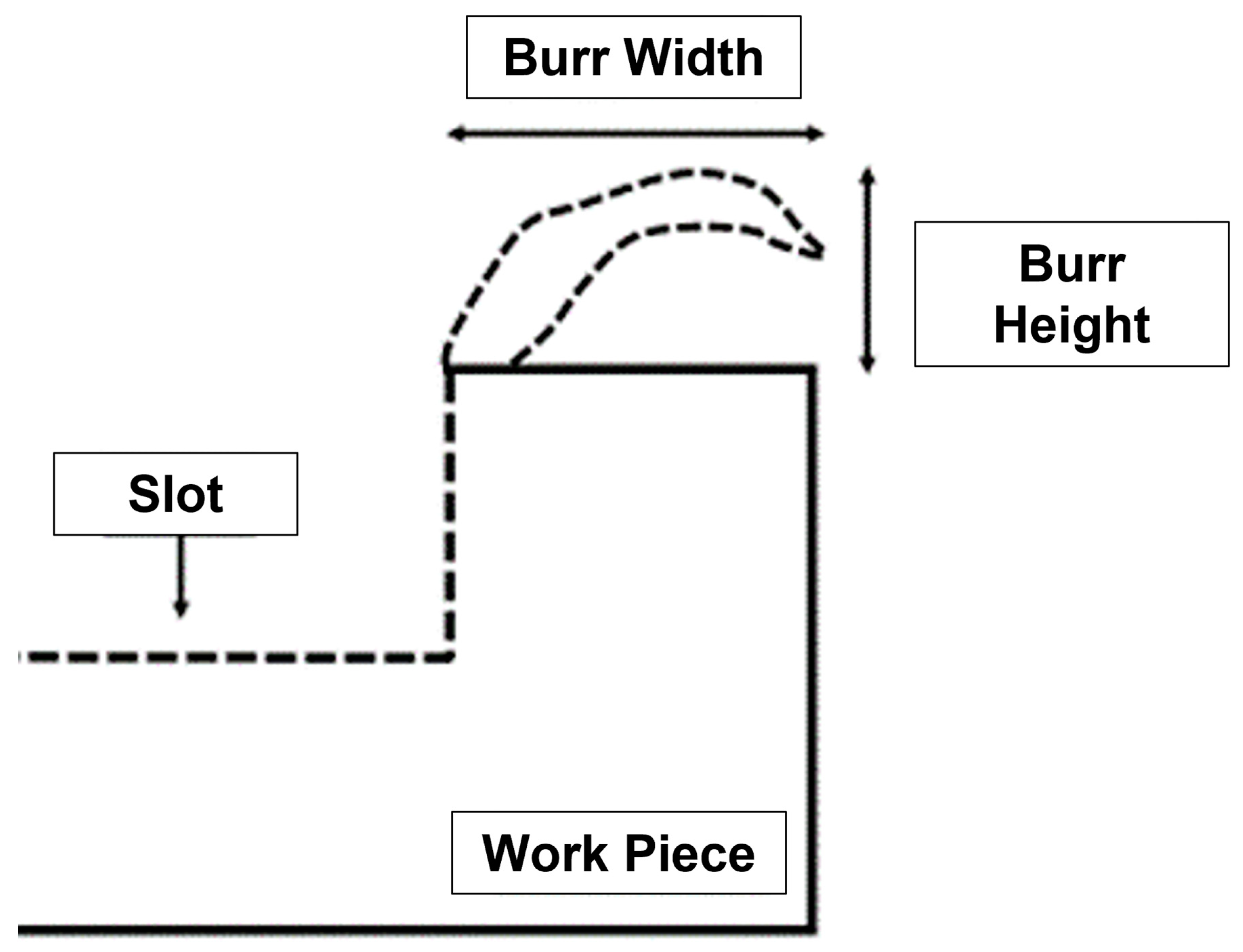
3.3. Response Measurement

Tool wear, surface roughness and burr measurement were measured and analyzed during the conduct of the research. An Olympus DXS1000 digital microscope was used to quantify the tool wear response. One such insert is displayed in Figure 4, depicting tool wear. In addition, the Olympus DXS1000 digital microscope was utilized to examine the surface roughness (refer to Figure 5) owing to its capability to ascertain micro-surface roughness with high precision. Surface roughness for each machining condition was measured at 5 separate locations, and average value was determined to ensure accuracy. ISO 21920-2:2021 [40] was referred to for specification of surface roughness. With reference to burr analysis, there are various points on a machined surface where burrs can develop, including top, bottom, entrance and exit burrs, as shown in Figure 6. In the current study, the top and down burr height and width were the main areas of interest during burr analysis. Measurements of burr width and burr height were made, as depicted in Figure 7, using the DXS1000 digital microscope. Each machining combination was conducted three times to measure output response. The output responses were then used to analyze various aspects of the machinability of Inconel 718, including the effects of input parameters, as well as identification of influential machining parameters in terms of contribution ratio. The complete research methodology of the current work is displayed in Figure 8.

4. Results and Discussion

Experimental results for output responses including tool wear, surface roughness and burr formation were recorded working with a Taguchi design of experiment, as explained in Section 3.2. These results are displayed in Table 4. The output responses were selected keeping in view manufacturing system productivity. Tool wear is a vital response parameter indicative of manufacturing process economy. In addition, other significant responses including surface roughness (product quality) and energy consumption (process sustainability) depend upon tool wear. Tool wear has a negative impact on both the final product quality and the precision of the machining operation [41]. Keeping the above in view, tool wear was analyzed as an important factor in the machinability of Inconel 718. Surface roughness of machined parts is a significant phenomenon as it dictates product quality as well as product performance. The influence of surface roughness is more profound, especially in the micro-product industry, because of the need for precision and accuracy. Burr formation is a vital machining response owing to its impact on finished product quality, among other factors. It occurs on the edges of the machined surface, as already indicated in Section 3.3. Deburring a finished product is a challenging task at the micromachining level as it may change dimension distortion, in addition to causing other issues, including changes in elastic limit and residual stresses, as well as fatigue strength. Resultantly, it is imperative to keep the burr formation to a minimum. Burr analysis usually takes the burr width and burr height of both up-milling and down-milling into account. Experimental results obtained in the current research show that burr formation is more pronounced towards the down-milling side. The obvious reason for this occurrence is the lower comparative Vc towards the down-milling edge of the slot. Subsequent to the above discussion, it is inferred that the chosen output responses were selected keeping in view their importance in optimizing manufacturing output as well as their effects on other machining responses.
In order to investigate the machinability of Inconel 718, an in-depth analysis of the experimental results achieved during milling operation was carried out. The parametric results were interpreted through MINITAB statistical software. Initially, main effects plots were drawn, which are informative representations of the input parameters on output responses. Then, analysis of variance was conducted to identify the contribution ratio of machining inputs. Regression analysis provided the equations for machining responses as an explicit function of input variables. Contour plots were also drawn to identify favorable combinations of machining inputs for higher output parameters. Individual analysis of machining responses is covered in succeeding sections.

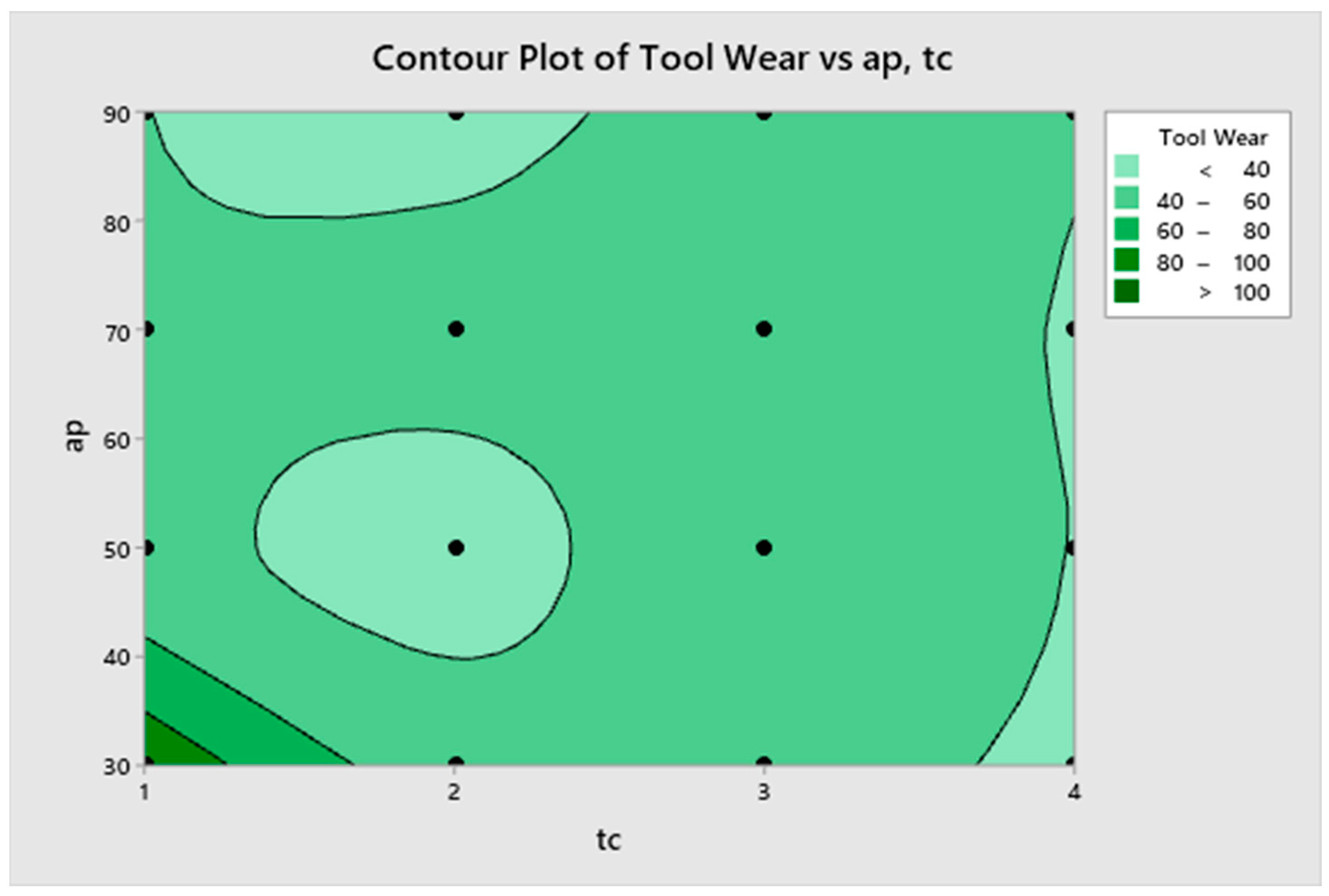
4.1. Tool Wear Analysis

The main effects plot and analysis of variance for the experimental results for tool wear are given in Figure 9 and Table 5, respectively. The main effects plot shows the individual effect of input parameters on tool wear. The effect of Vc on tool wear is represented by an initially decreasing and then increasing trend. This is due to the shift of the machining range from conventional machining to the transition region. In terms of fz, the tool wear decreased to a minimum at 0.5 fz, which is, in fact, the tool edge radius. It is due to the higher elastic recovery that working at fz equals the cutting tool radius during machining. A similar effect was observed for other workpiece materials by past researchers. The influence of these parameters was evident in the analysis of variance in terms of contribution ratio. The statistical result highlighted that tc and ap were most influential input parameters, with 36.19% and 25.51% contribution ratios. The uncoated micro tool caused the least wear among all tools, with the AlTiN coating being the second most effective tool. The nACo tool caused excessive tool wear. The reason for this occurrence is the highest thermal conductivity of the nACo-coated tool. Ap displayed a trend of reduced tool wear at higher values. On the other hand, tool wear initially decreased and then elevated with both Vc and fz. Nevertheless, Vc and fz proved to be moderate machining inputs with contribution ratios of 16.26% and 12.35%, respectively. Analysis of tool wear highlighted the effectiveness of the selected machining variables. Close observation of the main effects plot identified input parameters of 24 Vc, 0.50 fz μm/tooth, 90 μm ap as the optimum combination of input parameters for least tool wear when working with the uncoated micro tool. Similarly, the highest tool wear can be achieved at 9 m/min Vc, 0.25 fz μm/tooth, 30 μm ap using a nACo-coated micro tool. These conditions were validated later in the conduct of the research. Regression analysis for tool wear yields four separate equations (Equations (1)–(4)). The reason for this occurrence is the categorical Input parameter of tc. The trend of tool wear can also be equated with the positive intercept of the regression equations. The equation for the uncoated micro tool had a positive gain of 3%, 16% and 26% over AlTiN-, TiSiN- and nACo-coated micro tools. In Figure 10, the contour plot for tool wear is given, which is a graphical representation of the output response. Here, points of favorable outcome can be ascertained. To ascertain the tool wear inflicted on the milling insert, both cutting edges are shown in a close-up image in Figure 11. The images highlight the tool wear which occurred during the cutting of Inconel 718 experiments. The brighter portion labeled on both images indicates the tool wear. The initial dominant tool wear mechanism is abrasive wear, which is mechanical in nature. Then, as the machining progresses, the workpiece material smears onto the cutting edge, resulting in a built-up edge which eventually breaks off, taking a portion of the insert. This occurs periodically when the insert comes into contact with the workpiece under the force of flowing chips. Resultantly, the cutting edge becomes dull, which increases the surface roughness on the newly machined workpiece surface. Surface roughness, which is a vital product quality index, is discussed in Section 4.2.
TW (nACo) = 90.2 − 0.798 Vc − 8.34 fz − 0.2433 ap
TW (AlTiN) = 73.9 − 0.798 Vc − 8.34 fz − 0.2433 ap
TW (TiSiN) = 82.9 − 0.798 Vc − 8.34 fz − 0.2433 ap
TW (Uc) = 71.6 − 0.798 Vc − 8.34 fz − 0.2433 ap

4.2. Surface Roughness Analysis

The main effects plot and analysis of variance of input cutting parameters, along with different tool coatings on surface finish, are given in Figure 12 and Table 6, respectively. With respect to Vc, surface roughness tended to slightly decrease before elevating as Vc was increased from 9 to 24. The effect of tc on surface roughness was also evident, with the AlTiN-coated tool yielding the best product quality. This is owing to the low thermal coefficient, which keeps the cutting zone temperature in check. This results in lower tool wear which, in turn, produces better surface quality. It can also be seen that surface integrity diminished with an increase in both fz and ap, although the effect was minimal and seems insignificant. A higher fz facilitates a higher volume of machining. The surface quality is affected by tool wear brought on by a machining operation, as already mentioned above. One of the most important elements in surface finish is the tool’s cutting edge radius [42]. It is preferable to micro-mill on the smallest chips in order to create good surface roughness because doing so minimizes surface distortion and therefore enhances surface clarity. The best and worst results in terms of surface roughness were predicted to occur at 19 m/min Vc, 0.25 fz μm/tooth, 70 μm ap with the AlTiN-coated tool and 24 m/min Vc, 1.00 fz μm/tooth, 50 μm ap with the TiSiN-coated tool, respectively. In order to quantify the influence of input variables on surface roughness, analysis of variance was conducted, with results displayed in Table 6. Fz and ap were found to be insignificant owing to their meager effect on surface roughness, whereas Vc and tc were identified as the most effective members with contribution ratios of 51.24% and 34.27%, respectively. Another comparison of the different tool coatings used in this work was made through the analysis of regression equations, as given by Equations (5)–(8). The equation for the AlTiN-coated tool was the most efficient, with the least positive intercept of 0.0402, as it was based on a smaller-the-better model. In comparison, the AlTiN tool was 17%, 49% and 91% more effective than the nACo-coated, uncoated and TiSiN-coated tools, respectively. In order to find the optimum combinations of vital inputs, a contour plot was drawn. The result is displayed in Figure 13. Here, the brighter area of the graph represents better surface finish. The black circular points highlight the combination of various tc values at certain Vc values. This is a substantial visual tool for optimizing the output response.
SR (nACo) = 0.0472 + 0.000802 Vc + 0.0143 fz + 0.000004 ap
SR (AlTiN) = 0.0402 + 0.000802 Vc + 0.0143 fz + 0.000004 ap
SR (TiSiN) = 0.0770 + 0.000802 Vc + 0.0143 fz + 0.000004 ap
SR (Uc) = 0.0599 + 0.000802 Vc + 0.0143 fz + 0.000004 ap

4.3. Burr Formation Analysis

The effect of individual input parameters is displayed as the main effects plot given in Figure 14. One observation related to tc is that the nACo-coated tool produced the smallest burr in all cases, except in case of of burr width when down-milling. On the contrary, the TiSiN-coated tool yielded the highest recorded burr width and burr height in both up-milling and down-milling conditions. A probable reason for this is the highest coefficient of friction of the TiSiN-coated tool, resulting in intense shear deformation during milling. The cutting edge radius (mentioned in Section 3.1) is a significant parameter in comparison to fz since, at fz values higher than the cutting radius, lesser burrs were formed. Furthermore, it was found that increasing Vc resulted in a larger burr because Vc caused significant changes in cutting temperature [43]. A significant positive shift in burr formation was observed at 0.5 mm, which is the cutting edge radius of the milling tool. The exact effect of input variables was quantified using analysis of variance, given in Table 7, Table 8, Table 9 and Table 10. Ap was identified as the significant input in the case of burr height for both up-milling and down-milling with contribution ratios of 45.12% and 23.25%. On the other hand, fz was the dominant parameter for burr width, having contribution ratios of 39.28% and 36.26% for up-milling and down-milling, respectively. For burr height and burr width (up-milling), Vc proved to be insignificant, whereas ap was found to be insignificant for burr width during both up-milling and down-milling machining. Tc was singled out as the input variable with significant influence on process output (burr formation) in all four cases analyzed. The optimum conditions for minimum burring for the four desired cases (burr height and burr width for both up-milling and down-milling) were noted for the conduct of subsequent validation experiments.

5. Validation Tests

The current research focuses on the analysis of output response with tool coatings as the input variable in addition to other fundamental machining parameters. Such a methodology initially requires the identification of significant input variables in terms of their contribution ratio followed by selection of their discrete values which will contribute towards optimization. In this research, tool wear, surface roughness and burr formation were selected, based on the smaller-is-better model. Table 11 displays the desired values of input parameters as identified through the main effects plot in Section 4. Resultantly, validation experiments under these conditions were performed to confirm the authenticity of the obtained results. These results are given in Table 12. Here, 3 out of the 12 machining parameter combinations were already experimented on during the initial design of the experiment (L16 orthogonal array). The rest of the conditions were run three times each. It was observed that all best and worst output response conditions yielded corroborative results.

6. Conclusions

In the current experimental research, Inconel 718 was micromachined using end mills with different coatings to analyze the effects of input machining parameters on tool wear, surface roughness and burr formation. The following conclusions were reached during the conduct of this work:
  • Tool wear was found to be significantly affected by cutting speed, feed rate, depth of cut and tool coating, with tool coating bearing the highest contribution ratio of 36.19%;
  • Abrasion and chipping were found to be the dominant tool wear mechanisms;
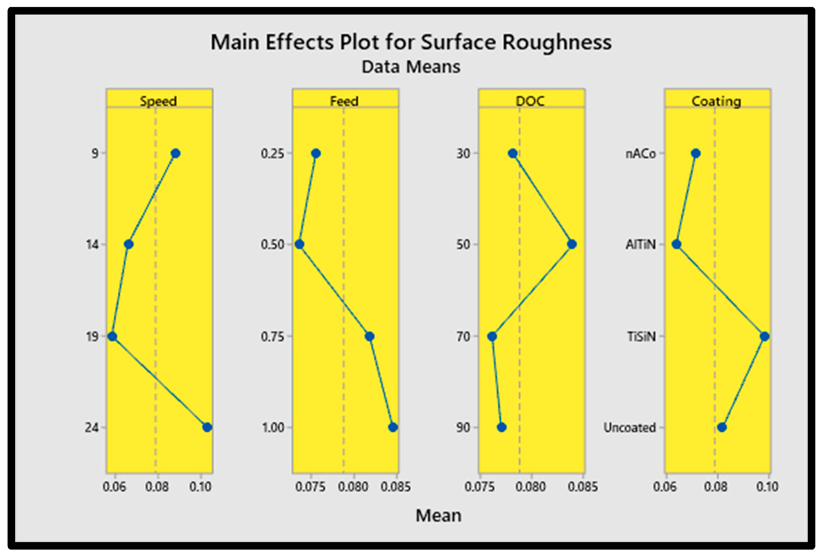
  • Cutting speed and tool coating had contribution ratios of 51.24% and 34.27%, respectively, on surface roughness response;
  • Analysis of regression equations for surface roughness determined positive gains of 17%, 49% and 91% using the AlTiN-coated tool over the nACo-coated, uncoated and TiSiN-coated tools;
  • Burr formation analysis identified depth of cut as an influential parameter for burr height formation for both up-milling (39.28%) and down-milling (36.26%);
  • Cutting tool edge radius is a vital input parameter affecting burr formation;
  • Tool coating input was singled out as the only parameter significantly affecting all machining responses;
  • Validation of confirmatory experiments endorsed the accuracy of the experimental procedure by improving the output responses.

Author Contributions

Conceptualization, M.I.F.; Data curation, M.I.F.; Formal analysis, M.I.F. and J.P.; Investigation, M.I.F.; Methodology, J.P.; Resources, J.P.; Software, J.P.; Supervision, J.P.; Validation, M.I.F.; Visualization, J.P.; Writing—original draft, M.I.F.; Writing—review and editing, J.P. All authors have read and agreed to the published version of the manuscript.

Funding

The work was funded through the Department of Machining, Assembly and Engineering Metrology, Mechanical Engineering Faculty, VŠB-Technical University of Ostrava, 17. Listopadu 2172/15, 708 00 Ostrava, Czech Republic. This work was supported by the Deanship of Scientific Research, Vice Presidency for Graduate Studies and Scientific Research, King Faisal University, Saudi Arabia (Grant no. 5335).

Data Availability Statement

Data of the research are being used for further extended research and can be made available in due course.

Conflicts of Interest

The authors declare no conflicts of interest.

References

  1. Jain, V.K.; Patel, D.S.; Ramkumar, J.; Bhattacharyya, B.; Doloi, B.; Sarkar, B.R.; Ranjan, P.; Sarath Sankar, E.S.; Jayal, A.D. Micro-machining: An overview (Part II). J. Micromanuf. 2022, 5, 46–73. [Google Scholar] [CrossRef]
  2. Chen, N.; Li, H.N.; Wu, J.; Li, Z.; Li, L.; Liu, G.; He, N. Advances in micro milling: From tool fabrication to process outcomes. Int. J. Mach. Tools Manuf. 2021, 160, 103670. [Google Scholar] [CrossRef]
  3. Corbett, J.; McKeown, R.A.; Peggs, G.N.; Whatmore, R. Nanotechnology: International developments and emerging products. CIRP Ann. 2000, 49, 523–545. [Google Scholar] [CrossRef]
  4. Kiswanto, G.; Azmi, M.; Mandala, A.; Ko, T.J. The Effect of Machining Parameters to the Surface Roughness in Low Speed Machining Micro-milling Inconel 718. In Proceedings of the IOP Conference Series: Materials Science and Engineering, Incheon, Republic of Korea, 19–22 August 2019; Volume 654. [Google Scholar]
  5. Schuster, R.; Kirchner, V.; Allongue, P.; Ertl, G. Electrochemical micromachining. Science 2000, 289, 98–101. [Google Scholar] [CrossRef] [PubMed]
  6. Kock, M.; Kirchner, V.; Schuster, R. Electrochemical micromachining with ultrashort voltage pulses-a versatile method with lithographical precision. Electrochim. Acta 2003, 48, 3213–3219. [Google Scholar] [CrossRef]
  7. Kim, B.H.; Ryu, S.H.; Choi, D.K.; Chu, C.N. Micro electrochemical milling. J. Micromechanics Microengineering 2005, 15, 124–129. [Google Scholar] [CrossRef]
  8. Attanasio, A. Tool run-out measurement in micro milling. Micromachines 2017, 8, 221. [Google Scholar] [CrossRef] [PubMed]
  9. Liu, Y.; Zhu, D.; Zhu, L. Micro electrochemical milling of complex structures by using in situ fabricated cylindrical electrode. Int. J. Adv. Manuf. Technol. 2012, 60, 977–984. [Google Scholar] [CrossRef]
  10. Xu, L.; Zhao, C. Nanometer-scale accuracy electrochemical micromachining with adjustable inductance. Electrochim. Acta 2017, 248, 75–78. [Google Scholar] [CrossRef]
  11. Bissacco, G.; Hansen, H.N.; De Chiffre, L. Size effects on surface generation in micro milling of hardened tool steel. CIRP Ann. 2006, 55, 593–596. [Google Scholar] [CrossRef]
  12. Mian, A.J.; Driver, N.; Mativenga, P.T. Identification of factors that dominate size effect in micro-machining. Int. J. Mach. Tools Manuf. 2011, 51, 383–394. [Google Scholar] [CrossRef]
  13. Ling, S.; Li, M.; Liu, Y.; Wang, K.; Jiang, Y. Improving machining localization and surface roughness in wire electrochemical micromachining using a rotating ultrasonic helix electrode. Micromachines 2020, 11, 698. [Google Scholar] [CrossRef] [PubMed]
  14. Allegri, G.; Colpani, A.; Ginestra, P.S.; Attanasio, A. An experimental study on micro-milling of a medical grade Co-Cr-Mo alloy produced by selective laser melting. Materials 2019, 12, 2208. [Google Scholar] [CrossRef] [PubMed]
  15. Wu, M.; Saxena, K.K.; Guo, Z.; Qian, J.; Reynaerts, D. Fast fabrication of complex surficial micro-features using sequential lithography and jet electrochemical machining. Micromachines 2020, 11, 948. [Google Scholar] [CrossRef] [PubMed]
  16. Marrocco, V.; Modica, F.; Bellantone, V.; Medri, V.; Fassi, I. Pulse-type influence on the micro-edm milling machinability of Si3N4—Tin workpieces. Micromachines 2020, 11, 932. [Google Scholar] [CrossRef] [PubMed]
  17. Rahman, M.A.; Ali, M.Y.; Rosli, A.R.S.; Banu, A. Process Capability of High Speed Micro End-Milling of Inconel 718 with Minimum Quantity Lubrication. In Proceedings of the IOP Conference Series: Materials Science and Engineering, Kuala Lumpur, Malaysia, 25–27 July 2016; Volume 184. [Google Scholar]
  18. Markopoulos, A.P.; Karkalos, N.E.; Mia, M.; Pimenov, D.Y.; Gupta, M.K.; Hegab, H.; Khanna, N.; Aizebeoje Balogun, V.; Sharma, S. Sustainability assessment, investigations, and modelling of slot milling characteristics in eco-benign machining of hardened steel. Metals 2020, 10, 1650. [Google Scholar] [CrossRef]
  19. Tadavani, S.A.; Razavi, R.S.; Vafaei, R. Pulsed laser-assisted machining of Inconel 718 superalloy. Opt. Laser Technol. 2017, 87, 72–78. [Google Scholar] [CrossRef]
  20. Reddy, M.M.; Nie, V.Y.C. Evaluation of surface roughness and tool wear in high speed machining of Inconel 718. In Materials Science Forum; Trans Tech Publications: Stafa-Zurich, Switzerland, 2018; Volume 943, pp. 66–71. [Google Scholar]
  21. Ucun, I.; Aslantas, K.; Bedir, F. An experimental investigation of the effect of coating material on tool wear in micro milling of Inconel 718 super alloy. Wear 2013, 300, 8–19. [Google Scholar] [CrossRef]
  22. Lu, X.; Jia, Z.; Wang, H.; Si, L.; Wang, X. Surface roughness prediction model of micro-milling Inconel 718 with consideration of tool wear. Int. J. Nanomanuf. 2016, 12, 93–108. [Google Scholar] [CrossRef]
  23. Aslantas, K.; Hopa, H.E.; Percin, M.; Ucun, I.; Çicek, A. Cutting performance of nano-crystalline diamond (NCD) coating in micro-milling of Ti6Al4V alloy. Precis. Eng. 2016, 45, 55–66. [Google Scholar] [CrossRef]
  24. Özel, T.; Thepsonthi, T.; Ulutan, D.; Kaftanolu, B. Experiments and finite element simulations on micro-milling of Ti-6Al-4V alloy with uncoated and cBN coated micro-tools. CIRP Ann. 2011, 60, 85–88. [Google Scholar] [CrossRef]
  25. Aramcharoen, A.; Mativenga, P.T.; Yang, S.; Cooke, K.E.; Teer, D.G. Evaluation and selection of hard coatings for micro milling of hardened tool steel. Int. J. Mach. Tools Manuf. 2008, 48, 1578–1584. [Google Scholar] [CrossRef]
  26. Devillez, A.; Le Coz, G.; Dominiak, S.; Dudzinski, D. Dry machining of Inconel 718, workpiece surface integrity. J. Mater. Process. Technol. 2011, 211, 1590–1598. [Google Scholar] [CrossRef]
  27. Tansel, I.N.; Arkan, T.T.; Bao, W.Y.; Mahendrakar, N.; Shisler, B.; Smith, D.; McCool, M. Tool wear estimation in micro-machining. Int. J. Mach. Tools Manuf. 2000, 40, 609–620. [Google Scholar] [CrossRef]
  28. Attanasio, A.; Gelfi, M.; Pola, A.; Ceretti, E.; Giardini, C. Influence of material microstructures in micromilling of Ti6Al4V alloy. Materials 2013, 6, 4268–4283. [Google Scholar] [CrossRef] [PubMed]
  29. Sun, Z.; To, S. Effect of machining parameters and toolwear on surface uniformity in micro-milling. Micromachines 2018, 9, 268. [Google Scholar] [CrossRef] [PubMed]
  30. Aurich, C.; Bohley, M.; Reichenbach, I.G.; Kirsch, B. Surface quality in micro milling: Influences of spindle and cutting parameters. CIRP Ann. 2017, 66, 101–104. [Google Scholar] [CrossRef]
  31. Pradhan, P.; Costa, L.; Rybski, D.; Lucht, W.; Kropp, J.P. A Systematic Study of Sustainable Development Goal (SDG) Interactions. Earth’s Future 2017, 5, 1169–1179. [Google Scholar] [CrossRef]
  32. IEA. World Energy Outlook 2018: Highlights; International Energy Agency (IEA): Paris, France, 2018; pp. 1–661. [Google Scholar]
  33. Kumar, R.; Bilga, P.S.; Singh, S. Multi objective optimization using different methods of assigning weights to energy consumption responses, surface roughness and material removal rate during rough turning operation. J. Clean. Prod. 2017, 164, 45–57. [Google Scholar] [CrossRef]
  34. Thakur, D.G.; Ramamoorthy, B.; Vijayaraghavan, L. Machinability investigation of Inconel 718 in high-speed turning. Int. J. Adv. Manuf. Technol. 2009, 45, 421–429. [Google Scholar] [CrossRef]
  35. Hughes, I.; Sharman, A.R.C.; Ridgway, K. The effect of cutting tool material and edge geometry on tool life and workpiece surface integrity. Proc. Inst. Mech. Eng. Part B J. Eng. Manuf. 2006, 220, 93–107. [Google Scholar] [CrossRef]
  36. Barry, J.; Byrne, G.; Lennon, D. Observations on chip formation and acoustic emission in machining Ti-6Al-4V alloy. Int. J. Mach. Tools Manuf. 2001, 41, 1055–1070. [Google Scholar] [CrossRef]
  37. Liu, R.; Mittal, S. Single-step superfinish hard machining: Feasibility and feasible cutting conditions. Robot. Comput. Integr. Manuf. 1996, 12, 15–27. [Google Scholar] [CrossRef]
  38. Zhou, M.; Chen, Y.; Zhang, G. Force prediction and cutting-parameter optimization in micro-milling Al7075-T6 based on response surface method. Micromachines 2020, 11, 766. [Google Scholar] [CrossRef] [PubMed]
  39. Karna, S.K.; Sahai, R. An Overview on Taguchi Method. Int. J. Eng. Math. Sci. 2016, 1, 11–18. [Google Scholar]
  40. ISO 21920-2:2021; Geometrical Product Specifications (Gps)—Surface Texture: Profile—Part 2: Terms, Definitions. ISO: Geneva, Switzerland, 2021.
  41. Dadgari, A.; Huo, D.; Swailes, D. Investigation on tool wear and tool life prediction in micro-milling of Ti-6Al-4V. Nanotechnol. Precis. Eng. 2018, 1, 218–225. [Google Scholar] [CrossRef]
  42. Lu, X.; Jia, Z.; Wang, H.; Hu, X.; Li, G.; Si, L. Measurement-based modelling of cutting forces in micro-milling of Inconel 718. Int. J. Nanomanuf. 2017, 13, 1–11. [Google Scholar] [CrossRef]
  43. Muhammad, A.; Gupta, M.K.; Mikołajczyk, T.; Pimenov, D.Y.; Giasin, K. Effect of Tool Coating and Cutting Parameters on Surface Roughness and Burr Formation during Micromilling of Inconel 718. Metals 2021, 11, 167. [Google Scholar] [CrossRef]
Figure 1. CNC milling machine—model PARPAS PHS-680.
Machines 12 00004 g001
Figure 2. Tools used for experimentation.
Machines 12 00004 g002
Figure 3. Workpiece: (a) top view with milling pathways indicated; (b) side view depicting milling slot (not to scale).
Machines 12 00004 g003
Figure 4. Cutting edges indicated by red rectangles on milling insert.
Machines 12 00004 g004
Figure 5. Surface roughness measurement at yellow square.
Machines 12 00004 g005
Figure 6. Burr generation during milling operation.
Machines 12 00004 g006
Figure 7. Measurement of burr width and burr height.
Machines 12 00004 g007
Figure 8. Research methodology employed in this research.
Machines 12 00004 g008
Figure 9. Main effects plot of tool wear.
Machines 12 00004 g009
Figure 10. Contour plot for tool wear.
Machines 12 00004 g010
Figure 11. Close-up imagery of the milling insert highlighting tool wear.
Machines 12 00004 g011
Figure 12. Main effects plot of surface roughness.
Machines 12 00004 g012
Figure 13. Contour plot for surface roughness.
Machines 12 00004 g013
Figure 14. Main effects plot for burr formation: (a) burr width up-milling; (b) burr height up-milling; (c) burr width down-milling; (d) burr height down-milling.
Machines 12 00004 g014
Table 1. Experimental setup.
Milling MachineCNC—PARPAS PHS-680
Workpiece materialInconel 718
Number of flutes2
Cutting length10 mm
Table 2. Design of experiment.
VariablesCutting SpeedFeed RateDepth of CutCoatings
SymbolVcfzaptc
Unitm/minµm/toothµm-
Level 190.2530nACo
Level 2140.5050AlTiN
Level 3190.7570TiSiN
Level 4241.0090uncoated
Table 3. Taguchi L16 array.
RunInput Parameters
Vc (m/min)fz (μm/tooth)ap (μm)tc
190.2530nACo
290.550AlTiN
390.7570TiSiN
49190uncoated
5140.2550TiSiN
6140.530uncoated
7140.7590nACo
814170AlTiN
9190.2570uncoated
10190.590TiSiN
11190.7530AlTiN
1219150nACo
13240.2590AlTiN
14240.570nACo
15240.7550uncoated
1624130TiSiN
Table 4. Machining results for burr formation, surface roughness, tool wear.
Experimental RunOutput Parameters
Tool Wear (μm)Surface Roughness (μm)Burr Formation (μm)
Burr Height Burr Width
LeftRightLeftRight
Run 11100.1360.069102.128262.403338.413510.167
234.3470.077146.414447.613300.575473.983
346.8850.095251.747219.736505.049403.683
441.0080.09790.175488.132306.687337.734
552.9520.08451.642451.017268.437515.621
632.9430.049269.211172.141328.17326.356
742.4390.073124.613183.593373.504362.552
841.7820.051135.57108.263397.715247.718
937.1500.065141.336256.026285.573434.421
1047.9600.072118.741365.855386.71375.989
1155.0850.048108.777385.27260.425314.183
1249.5500.04686.94296.512407.228241.922
1329.1460.07166.358428.854293.971437.448
1442.8300.085128.374267.073298.751302.469
1542.7040.106102.557439.501368.26277.863
1647.4010.141246.965415.128429.231519.487
Run 2193.9280.075110.875269.711350.082501.435
235.3870.08158.148463.897317.229485.915
352.2400.101239.344211.59477.656384.953
444.9750.10481.693501.981292.37365.851
548.6820.08855.702448.484280.607499.432
634.7730.058249.916161.097346.381350.063
738.4310.067133.414200.584386.729343.168
846.7190.048127.917126.474371.155233.603
939.2120.067132.144277.834306.988424.72
1052.2350.081130.111376.536394.162388.951
1148.3860.051116.507379.438280.225297.243
1246.8510.04992.04781.982424.49258.925
1336.6030.07579.703442.548276.965416.622
1443.9850.093133.048254.069279.154319.625
1535.9100.113103.076426.707382.709265.496
1651.3810.134266.079411.81403.423514.937
Table 5. Analysis of variance for tool wear parameter.
SourceDFSeq SSContributionAdj SSAdj MSF-Valuep-Value
Vc31100.016.26%1100.0366.664.170.020
fz3835.712.35%835.7278.573.170.048
ap31387.925.51%1387.9462.645.260.008
tc31772.036.19%1772.0590.686.720.003
Lack of Fit31500.35.17%1500.3500.11
Pure Error16169.84.51%169.810.62
Total316765.8100.00%
Table 6. ANOVA for surface roughness parameter.
SourceDFSeq SSContributionAdj SSAdj MSF-Valuep-Value
Vc30.00941351.24%0.0094130.00313830.380.000
fz30.0005863.19%0.0005860.0001951.890.166
ap30.0001130.62%0.0001130.0000380.370.778
tc30.00629434.27%0.0062940.00209820.320.000
Lack of Fit30.0016869.18%0.0016860.000562
Pure Error160.0002761.51%0.0002760.000017
Total310.018368100.00%
Table 7. Analysis of variance for burr height up-milling parameter.
SourceDFSeq SSContributionAdj SSAdj MSF-Valuep-Value
Vc349314.07%4931.11643.70.940.439
fz323,93619.73%23,935.97978.64.580.014
ap342,61045.12%42,610.014,203.38.150.001
tc316,74413.80%16,743.65581.23.200.047
Lack of Fit332,18816.53%32,187.610,729.2187.620.000
Pure Error169150.75%915.057.2
Total31121,324100.00%
Table 8. Analysis of variance for burr height down-milling parameter.
SourceDFSeq SSContributionAdj SSAdj MSF-Valuep-Value
Vc3121,90623.30%121,90640,635.26.320.004
fz323,6324.52%23,6327877.21.230.328
ap3121,65323.25%121,65340,551.16.310.004
tc3133,90435.59%133,90444,634.76.950.000
Lack of Fit3120,76213.08%120,76240,254.1478.580.000
Pure Error1613460.26%134684.1
Total31523,203100.00%
Table 9. Analysis of variance for burr width up-milling parameter.
SourceDFSeq SSContributionAdj SSAdj MSF-Valuep-Value
Vc319811.61%1981660.50.250.863
fz336,08439.28%36,08412,028.14.480.015
ap334702.82%34701156.50.430.733
tc330,68334.90%30,68310,227.73.810.027
Lack of Fit348,27219.17%48,27216,090.893.940.000
Pure Error1627412.22%2741171.3
Total31123,232100.00%
Table 10. Analysis of variance for burr width down-milling parameter.
SourceDFSeq SSContributionAdj SSAdj MSF-Valuep-Value
Vc337,22814.50%37,22812,409.34.710.013
fz393,12036.26%93,12031,039.911.780.000
ap321,2698.28%21,2697089.72.690.075
tc355,10121.46%55,10118,366.86.970.002
Lack of Fit347,81310.62%47,81315,937.7113.360.000
Pure Error1622498.88%2249140.6
Total31256,780100.00%
Table 11. Machining condition sets for individual best and worst responses.
ResponsesConditionInput Parameters
Vc (m/min)fz (µm/tooth)ap (µm)tc
Tool Wear (µm)Best140.5090uncoated
Worst90.2530nACo
Surface Roughness (µm)Best190.2570AlTiN
Worst241.0050TiSiN
Burr Width (µm)LeftBest240.2590AlTiN
Worst90.7570TiSiN
RightBest190.7570uncoated
Worst90.2530TiSiN
Burr Height (µm)LeftBest190.2550nACo
Worst90.5030TiSiN
RightBest141.0070nACo
Worst240.2590TiSiN
Table 12. Results of validation tests.
Responses ConditionValidation TestInitial RunDifference
Tool Wear (µm)Best27.956 µm29.146 µm4.0%
WorstAlready examined100.136 µm-
Surface Roughness (µm)Best0.044 µm0.046 µm4.3%
Worst0.144 µm0.141 µm2.1%
Burr Width (µm)LeftBestAlready examined260.425 µm-
WorstAlready examined505.049 µm-
RightBest221.042 µm233.603 µm5.3%
Worst527.401 µm519.487 µm1.5%
Burr Height (µm)LeftBest48.972 µm51.642 µm5.1%
Worst274.075 µm269.211 µm1.8%
RightBest77.416 µm81.982 µm5.6%
Worst533.092 µm501.981 µm6.2%
Disclaimer/Publisher’s Note: The statements, opinions and data contained in all publications are solely those of the individual author(s) and contributor(s) and not of MDPI and/or the editor(s). MDPI and/or the editor(s) disclaim responsibility for any injury to people or property resulting from any ideas, methods, instructions or products referred to in the content.

