1. Introduction
Several studies have been conducted towards broadening the operational bandwidth of a vibration energy harvester (VEH) beyond the resonant region [
1,
2,
3,
4,
5,
6,
7]. To extend the operational bandwidth of a VEH system, the authors in [
1] investigated a broadband energy harvester whose function is based on a combination of nonlinear stiffening effect and multimodal energy harvesting in order to attain a high bandwidth over a broad range of excitations (0.1–2.0 g). In [
2], the author extended some previous studies on using movable masses to extend the bandwidth of VEHs. The author demonstrated a novel method that involved embedding liquid in the system’s mass, used to extend the bandwidth of the VEH or tune the frequency without a significant reduction in the power output. Ramlan et al., in [
3], demonstrated the potential benefits of nonlinear stiffness characteristics in energy harvesters. Two implementations of nonlinear stiffness characteristics were considered in the study. For the first implementation, using a bi-stable snap-through mechanism, it was shown that more electrical power was harvested, compared to a tuned linear device, for a given input excitation. Likewise, for the second implementation, using a hardening spring, it was also demonstrated that the bandwidth could also be extended, in comparison with an equivalent linear device. It should be noted that an equivalent linear VEH device provides the same maximum throw, at resonance, as the nonlinear VEH device of interest. Meanwhile, the maximum throw is dependent on the size of the VEH system (typically the electromagnetic type) and is defined as the maximum distance that the mass of the VEH system can travel. This constitutes a mass-displacement constraint for electromagnetic-type energy harvesters. Wang et al., in [
4], presented a novel automated method that tracks the resonant frequency of a VEH. The authors achieved this by employing a pair of cylindrical movable magnetic sliders on a cantilever beam, which increased the bandwidth of the VEH, as the slider could track the resonant frequency on the cantilever beam without manual involvement or external energy input. In [
5], the authors suggested tuning the resonant frequency of a VEH system to align with that of the excitation frequency and set the electrical damping to be equal to the parasitic damping. The system was implemented using power electronics circuits, which enabled the adjustment of both the damping characteristics and the resonant frequency, thus improving its efficiency. Studies in [
6,
7] focused on the comparison of the bandwidth provided by a Duffing-type energy harvester with that of an equivalent linear harvester. The results obtained also demonstrated that a nonlinear harvester provided a larger bandwidth compared to the linear equivalent. Most of the published works have compared the Duffing-type VEH with its equivalent linear device. In addition, several parameter optimisations have been suggested to achieve similar results. Such parameter optimisations include the use of a mechanical damping [
6], the integration of an optimum electrical load [
7,
8], and the application of multi-stage harvester models [
9,
10].
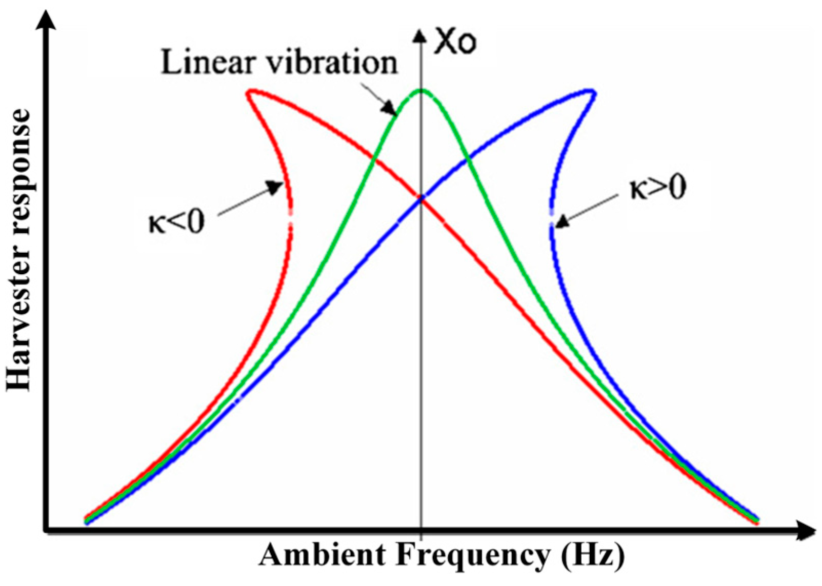
It has been evidently established in the literature [
11,
12,
13,
14,
15] that nonlinear stiffness behaviour, as depicted in
Figure 1, can be implemented using several geometric arrangements of permanent magnets, whose lines of flux cut across defined arrangements of copper coils. In [
11], a nonlinear dual-function multi-modal energy harvester and vibration absorber (EHVA) for harvesting energy and suppressing vibration in the low–medium frequency band, was presented. Two different methods were employed to extend the operating bandwidth of the system. These include the design of the multi-modal shapes of the EHVA as well as the hysteresis property of nonlinear softening springs, implemented by a novel permanent magnet structure. The authors in [
12] investigated the steady-state response of a specific VEH system under the condition of external and internal resonance, with a focus on the double jump phenomenon. The frequency response curve shows the existence of resonance peaks tilting to the left and right of the natural frequency of the system. Wang and Zhu in [
13] coupled a magnetic multi-stable device to a pendulum VEH in order to expand its bandwidth, specifically in low-frequency operation. In [
14], an experimental and theoretical study for designing a nonlinear electromagnetic converter-based magnetic spring was conducted. In this study, a special emphasis was given to the magnetic force acting on the moving magnet, based on two parameters—the volume of the magnets and the geometry of the two fixed magnets (i.e., disc or ring). Meanwhile, the authors in [
15] numerically analysed a magnetic-spring-based electromagnetic energy harvester with piecewise nonlinear stiffness. It was demonstrated that the piecewise nonlinear stiffness behaviour, developed due to the interactions of the moving magnet’s flux on the coil, facilitated the response of the system in a wider frequency range, enabling it to generate more electrical energy.
Similarly, system damping characteristics have been employed in optimising the energy harvested by vibration energy harvesters [
16,
17,
18,
19,
20,
21,
22,
23,
24]. In [
16], the authors presented an unconventional way of achieving a tuneable resonant frequency (from high frequency to ultralow frequency) and extending both the bandwidth and peak of the energy harvested, simultaneously, by utilising a distinct structurally supported displacement-dependent nonlinear damping property. This work was further extended by the authors in [
17], where a scissor-like energy harvesting system, with equivalent nonlinear damping and linear stiffness characteristics, was developed. It was demonstrated that the scissor structure provided beneficial nonlinear damping effects, thereby significantly improving the magnitude of the power harvested, as well as the bandwidth over which it was harvested. The beneficial effect of antisymmetric nonlinear damping on energy harvesters was demonstrated by the authors in [
18], when the system was subject to ambient random vibrations. Meanwhile, in [
19], a VEH which employs a complementary metal–oxide-semiconductor-compatible 3D micro-electromechanical system coils and a ferromagnetic core was presented. In order to describe the nonlinear electromagnetic damping coefficient and nonlinear attraction between the magnet and the ferromagnetic core, a systematic model was proposed. Thereafter, a vibration model was developed by considering nonlinear stiffness and damping coefficient to derive the dynamic characteristics and output performance of the system. The authors in [
20] proposed a novel H-bridge circuit-based electromagnetic damper which enables a bi-directional flow of electrical energy between the electromagnetic damper and the energy storage. It was also demonstrated that this process enables the realisation of diverse damping behaviour with salient self-powered feature.
The authors in [
21,
22] also employed nonlinear damping in extending the energy harvested by a vibration energy harvester. Based on the findings in [
21,
22], an analysis, design, and optimisation of a nonlinear VEH system was conducted in [
23,
24]. While no mass-displacement constraint was considered in [
23], this was considered in [
24]. In these studies, an optimum cubic damping parameter was designed for a desired power level using the Output Frequency Response Function (OFRF) method. The OFRF of a nonlinear system is determined based on the class of nonlinear differential equation (NDE) the system belongs to and it shows the relationship between the output spectrum of the system and its nonlinear parameters [
25,
26]. It, thus, describes the system characteristics. The OFRF representations of the systems studied in [
25,
26,
27,
28] were determined using the Least-Squares (LS) approach. However, this method requires several numerical simulations, using a (training) set of values of the system design parameters, to obtain the respective system output responses [
29].
Feijoo et al., in [
30], based on the characteristics of the nth-order Volterra operator being a multi-linear function of a combination of input signals, modelled the behaviour of the Volterra operators using their Associated Linear Equation (ALE) decompositions. These ALE decompositions, as discussed in [
30,
31], can be used as an analytical tool for analysing the Volterra class of nonlinear systems such as the Duffing equation. Based on this, it was further revealed in [
32,
33] that the ALE decompositions, for a Volterra class of nonlinear systems, can be used to determine a more accurate OFRF representation of the system, using a significantly lower number of numerical simulations, compared to the LS approach. These methods were further extended in [
34] to the Generalised Associated Linear Equation (GALE) decompositions, which considered a general class of nonlinear damping.
In this study, an analysis and design of a nonlinear VEH system is conducted using the OFRF representations of the system output spectra, which are determined from the GALE decompositions of the nonlinear VEH model. In addition to using a nonlinear damping component to extend the average power of the VEH, a stiffness nonlinearity is also integrated to widen the operational frequency range of the harvesting device. It should be noted that the current study is an extension of the initial work by the authors in [
33]. To the best of the authors’ knowledge, this is the first time the OFRF method, derived using the GALE decompositions, is employed in the design and optimisation of a nonlinear vibration energy harvester. Using the OFRF model, derived from the GALE decompositions, simplifies the design process since a polynomial of the system’s performance metrics is derived in terms of the design parameters. A sequel study involving an experimental validation of the design is currently ongoing.
Subsequent sections of this paper are organised as follows—
Section 2 presents the model formulation of the system of interest. In
Section 3, the OFRF method is introduced, while
Section 4 describes the determination of the OFRF structure.
Section 5 discusses the evaluation of the GALE decompositions and in
Section 6, the determination of the OFRF model using the decomposed GALE contributions is demonstrated.
Section 7 provides the results obtained and their corresponding discussions while the research findings are concluded in
Section 8.
2. Model Formulation
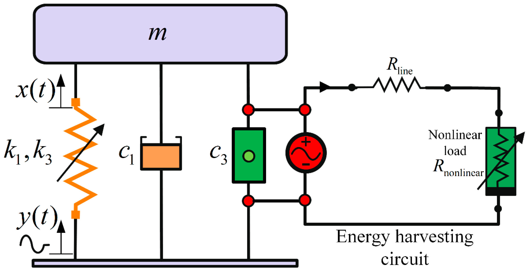
A single-degree-of-freedom (SDOF) vibration-based energy harvester, as illustrated in
Figure 2, having a suspended mass,
, and an oscillating support base with displacement,
, is given. The mass is separated from the base using an isolation system modelled as a nonlinear damping system connected parallel to a nonlinear spring. The damping system comprises a mechanical viscous damping,
, and an electrical damping,
. The electrical damping arises from the electromagnetic force generated by virtue of the non-Ohmic load resistance connected across the EM damper. The linear and cubic stiffness coefficients are
and
, respectively.
The model of the SDOF VEH is a class of NDE and the equation of motion of the mass with respect to the relative displacement,
, is given as
For a harmonic base displacement with amplitude,
, frequency,
, and zero phase shift, the base displacement is given as
. Therefore, Equation (1) becomes
The nonlinear damping device absorbs an instantaneous power equal to the product of the instantaneous damper force and relative velocity of the VEH. Therefore, it yields an average power given as
For a single-frequency harmonic oscillation, where
, yields
In addition, it can be deduced that the output frequency response, , of system (2), is a function of , as well as the nonlinear parameters and . This implies that , derived in Equation (4), is also a function of , , and . Note that the resonant frequency is the frequency of interest, as the maximum power is extracted at this frequency.
3. The Output Frequency Response Function (OFRF)
Equation (2) describes the dynamic model of the VEH system, which is a typical base-excited Duffing equation, with an integrated nonlinear damping. A similar system has been studied using methods such as the harmonic balance method [
35] and multiple scales [
36]. However, the aforementioned methods only facilitate the analytical study of nonlinear systems. On the other hand, the OFRF, which is employed in this study, does not only facilitate the analytical study of nonlinear systems but also enables the design and optimisation of such systems. However, for the OFRF method to perform appropriately, the system of interest must operate within a stable regime. The main benefit of the OFRF method is that it can provide an explicit analytical relationship between the design objective and the system nonlinear parameters. This can significantly facilitate the system’s design and optimisation process. A comprehensive explanation of the OFRF concept can be found in [
25,
26,
27,
28,
29].
Let us examine the differential equation in Equation (5), which describes a class of Volterra systems
where
is the maximum degree of nonlinearity, in terms of the system’s input,
, and output,
, and
is the order of the derivative. According to the OFRF method, as described in [
26], the output frequency response of Equation (5) can be described by a polynomial function in terms of the system nonlinear parameters as
where
is the maximum order of
for
in the polynomial expression of the output spectrum,
, of Equation (6). The OFRF coefficients,
, are frequency functions with complex values. They are also dependent on the system linear parameters and system input, where
and
. In addition,
is known as the OFRF structure. They are a set of monomials in terms of the system nonlinear characteristic parameters. If the set of monomials in the OFRF polynomial, of the nth-order output spectrum, is denoted as
and the vector of the frequency function is denoted as
, the OFRF can be then be described as
where
Here,
is the maximum order of nonlinearity considered for this study and the set of monomials
can be derived using the method in [
15] as
Note that the character ‘
’ is the Kronecker product and given by
Then, the set of monomials can be obtained as .
4. Determination of the OFRF Structure
Firstly, the OFRF representations of the output spectrum of system (2),
, and the harvestable average power of Equation (4),
, are obtained in terms of the design parameters,
and
. It is observed that Equation (2) belongs to the class of the Volterra system of Equation (5) in [
25], with
and
. The system parameters are obtained as
,
,
,
,
, and
.
If the set of monomials in the OFRF representation of the nth-order output spectrum of system (2) is denoted by
, and the complex-valued OFRF coefficients are denoted by
, then the OFRF representation can be written as
Applying the algorithm, as presented in [
37], to obtain the OFRF monomials,
, up to the 7th order, yields
Therefore, .
It should be noted that for improved accuracy, higher orders can be considered. Furthermore, the OFRF representation, as presented in Equation (11), which comprises the monomials obtained, as presented in Equation (12), and its respective OFRF coefficients,
(yet to be determined), can be represented in the form
where,
and
is the maximum number of elements in
. Rewriting Equation (13) yields
Thus, to determine the OFRF coefficients, , the GALE decompositions of system (2) are first computed up to the 7th order. In the next section, the evaluation of the GALE decompositions for the NDE system of interest is demonstrated.
5. Evaluation of the Generalised Associated Linear Equations (GALEs)
For a nonlinear system of the Volterra class given in system (2), the following substitutions can be made:
Rewriting system (2) in a general form, by leaving all the linear elements on the LHS and substituting Equation (15), yields
The GALE decompositions of system (16) can be obtained for the nth order, for
, where
is the maximum order of the system nonlinearity considered, as demonstrated in [
33,
34]; thus,
where the summation of all the sub-indices of
and
on the RHS has to be equal to
, i.e.,
and
. In computing the GALE decompositions, the low-order output responses contribute to the immediate higher-order responses up to the maximum order considered. For an estimation of the total output responses up to the
and its corresponding output spectrums,
For
, the following GALE decompositions are obtained:
The continuous time output response of system (2) and its corresponding output spectrum, where
, are, respectively, expressed as
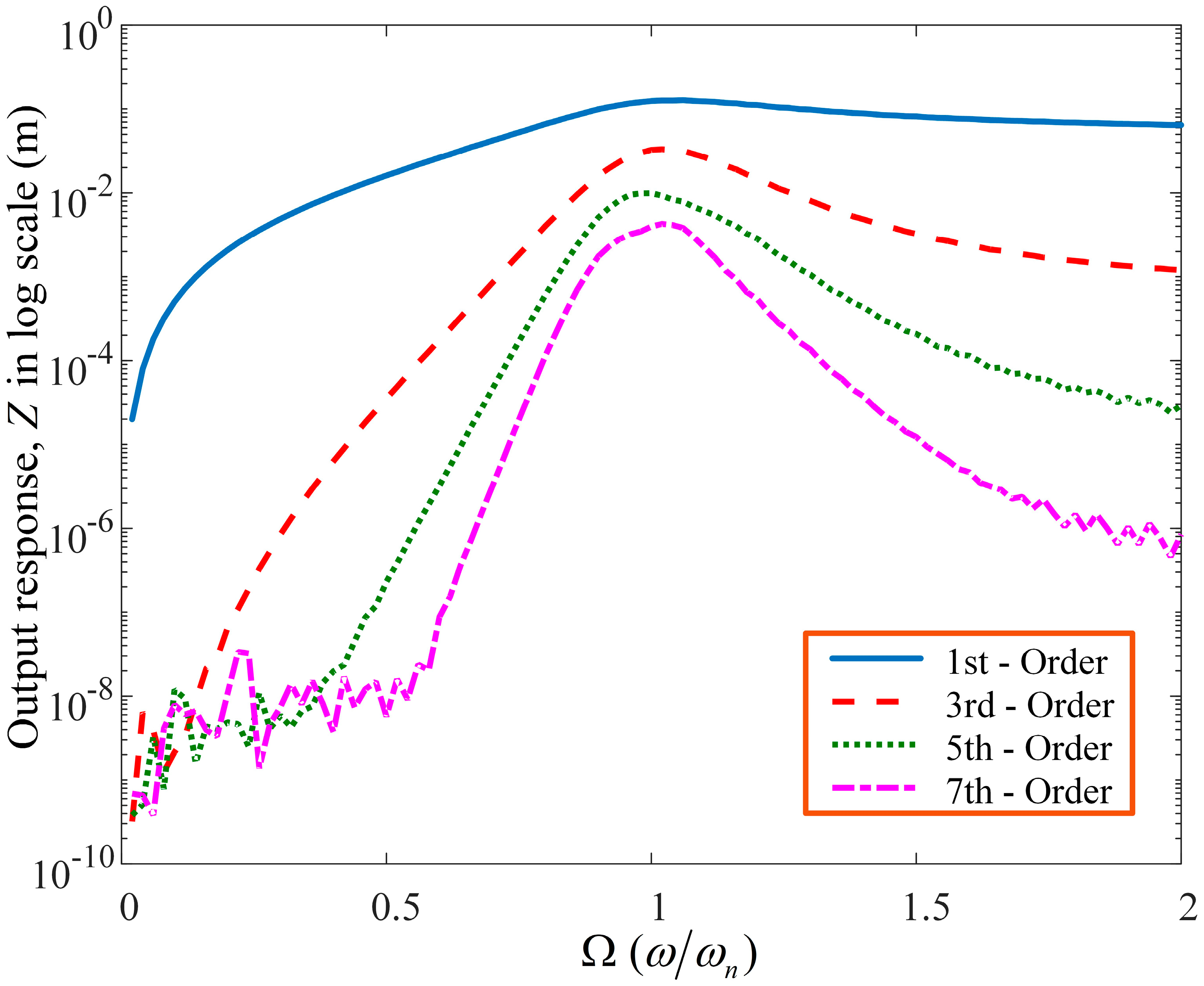
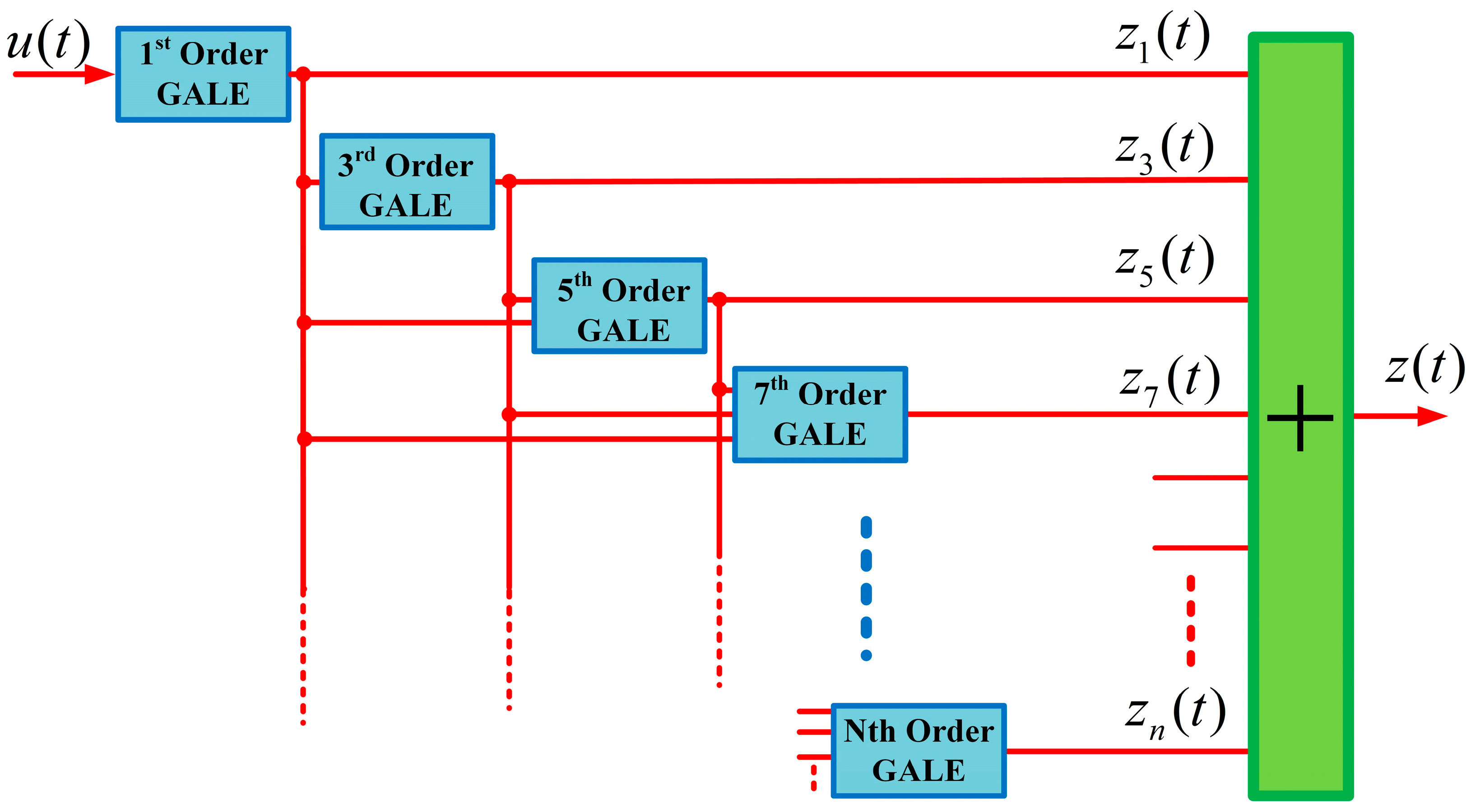
The cumulative structure of the individual nth-order GALE contributions, up to the 7th order, is presented in
Figure 3. Similarly,
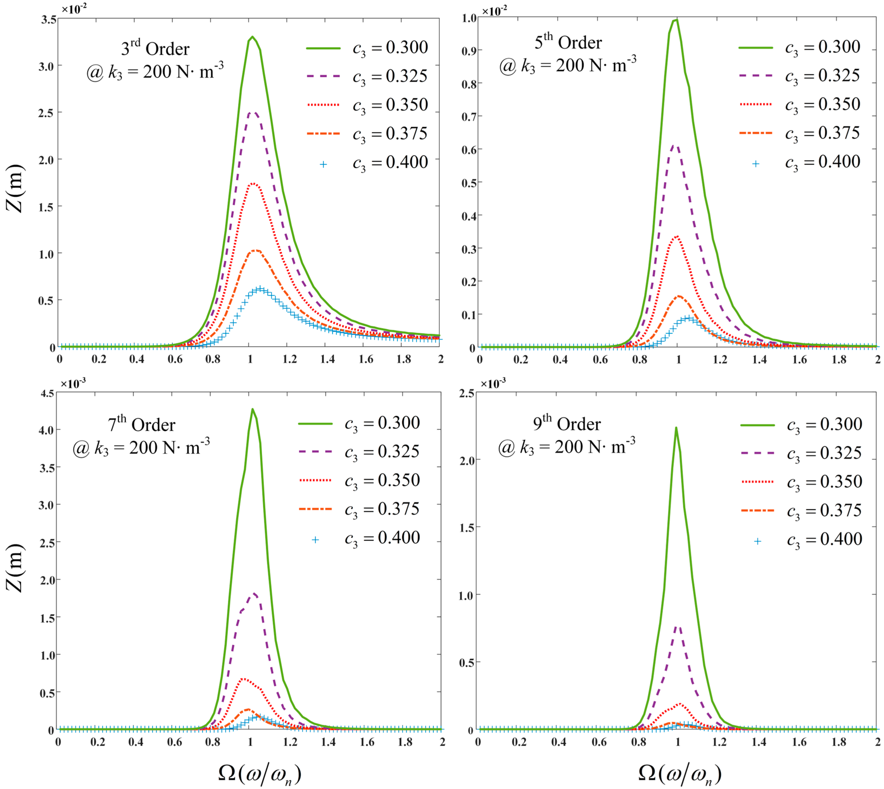
Figure 4 shows the output spectrum for each nth-order contribution of the GALE decompositions, up to the 7th order. It is observed that at resonance there is a significant contribution by the individual decompositions. Meanwhile,
Figure 5 demonstrates the nth-order contributions of the GALE decompositions up to the 9th order for a range of nonlinear damping values.
6. Determination of the OFRF Model Using the GALE Contributions
Equation (20) shows the output spectrum of system (2) determined from the Fast Fourier Transform of the GALE contributions obtained. The nth-order output spectrum of each GALE contribution is equal to the corresponding nth-order component of the OFRF representation; thus
From Equation (21), it can be deduced that
Subsequent analysis in this study was conducted using the following system parameter values presented in
Table 1 with
.
To obtain the OFRF coefficients up to the 7th order, five simulations are required using five different values of
and
, where
, as given in
Table 2.
The OFRF coefficients can be determined for any frequency of interest using Equation (23), given as
Therefore, the GALE-generated OFRF representation of the output spectrum of system (2) can be expressed as
The OFRF coefficients of Equation (24) were determined using the GALE approach. The benefit of using the GALE approach is that the number of numerical simulations required to determine the OFRF of the system is significantly reduced [
32]. To obtain the respective OFRF representation of the average power harvestable by the VEH system via the nonlinear damping system, the OFRF representation of the output spectrum in Equation (24) is substituted in Equation (4) to yield
The OFRF representation of the quartic magnitude of the output spectrum,
, can also be derived and represented in a polynomial form [
20] as
where
is the maximum nth-order nonlinearity while
are functions of frequency and represent the OFRF coefficients of
. Therefore, the average power can be represented as
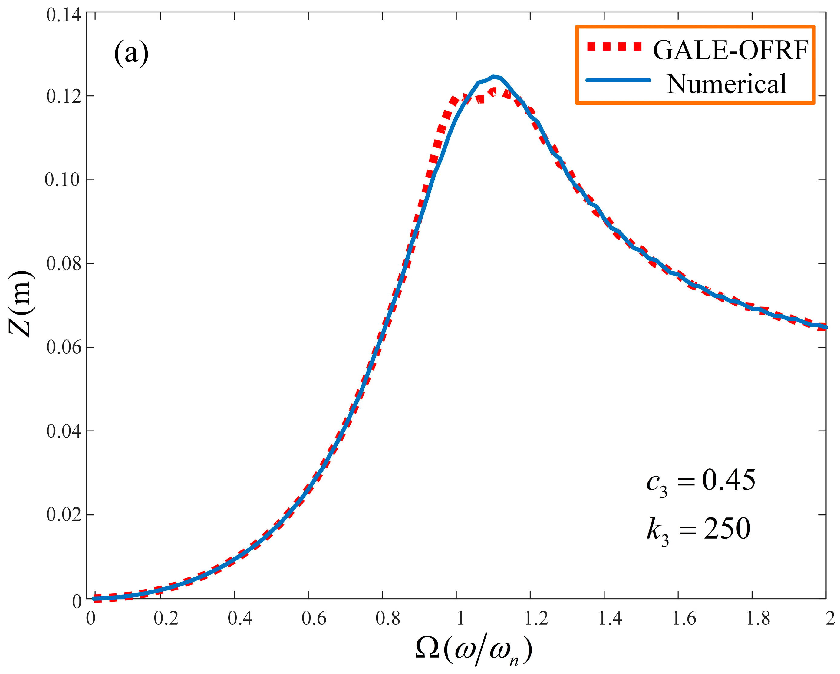
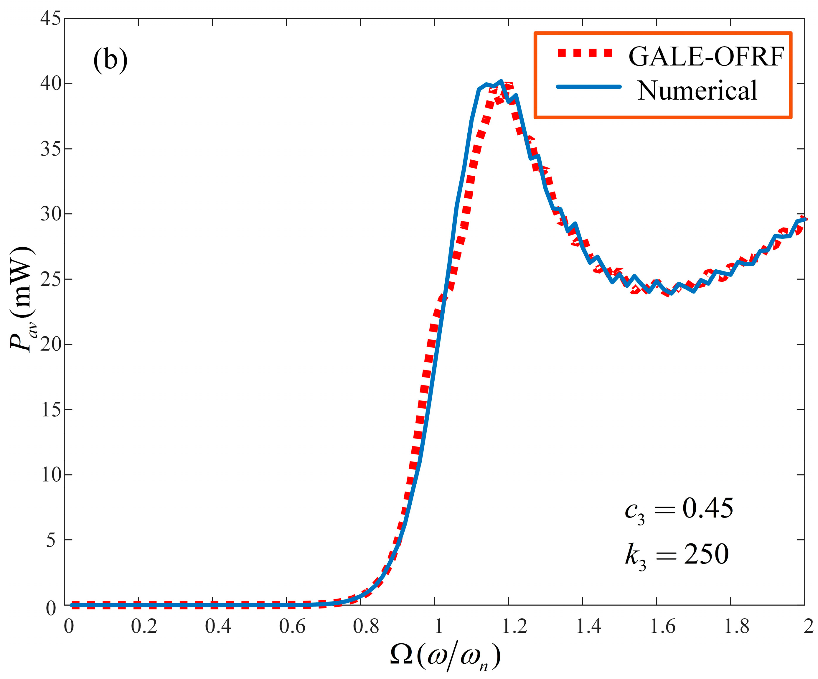
The OFRF-based results are obtained and compared with that determined using the Runge–Kutta 4 algorithm (ODE45 in MATLAB) for both the output spectrum of system (2) and the average power harvested by the VEH system. The comparisons were conducted for different combinations of parameter values beyond the training set of the nonlinear parameters
and
. The results are presented in
Figure 6 and
Figure 7 for the pair of parameters
= 0.45 Ns
3m
−3 and
= 250 Nm
−3, and
= 0.25 Ns
3m
−3 and
= 270 Nm
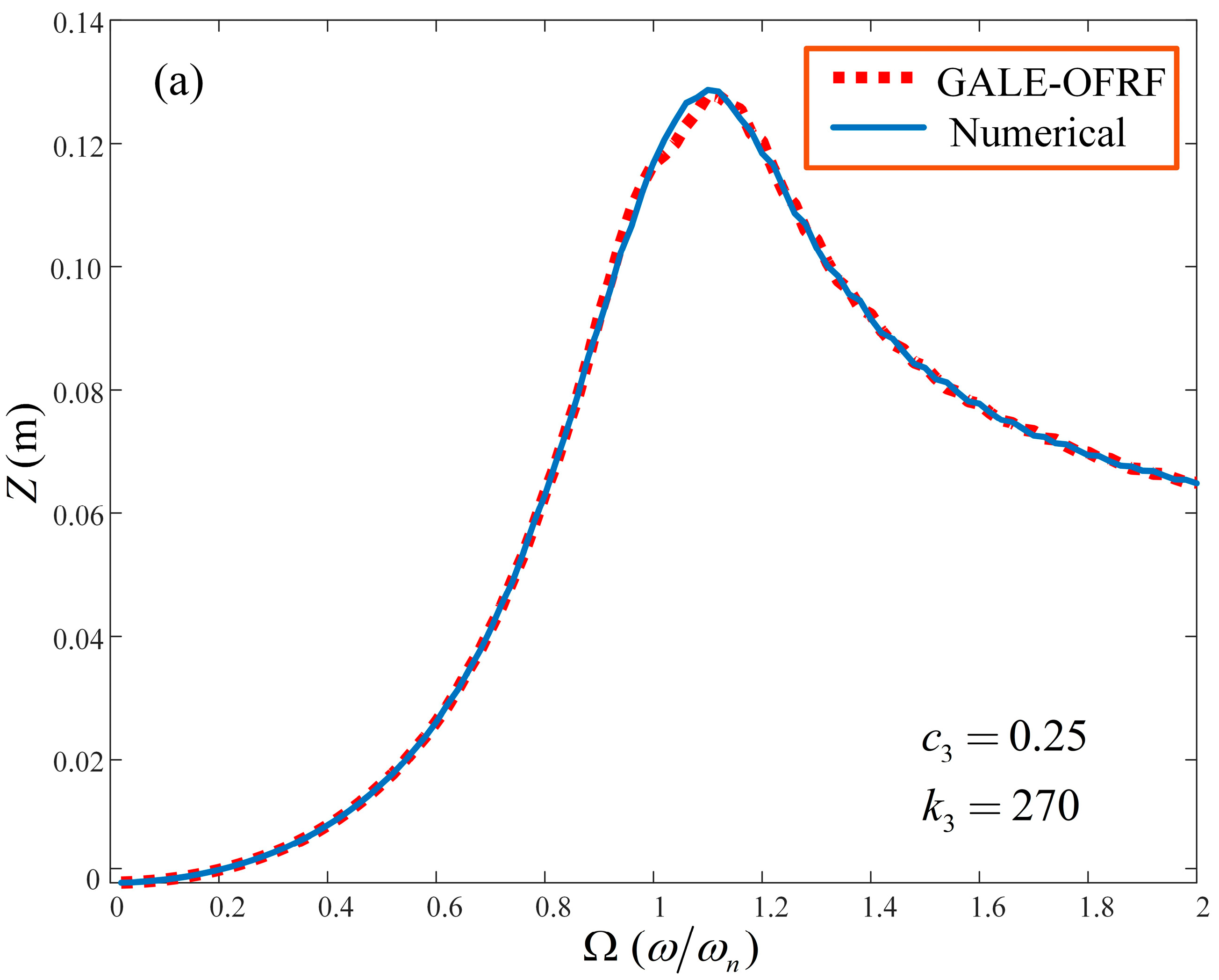
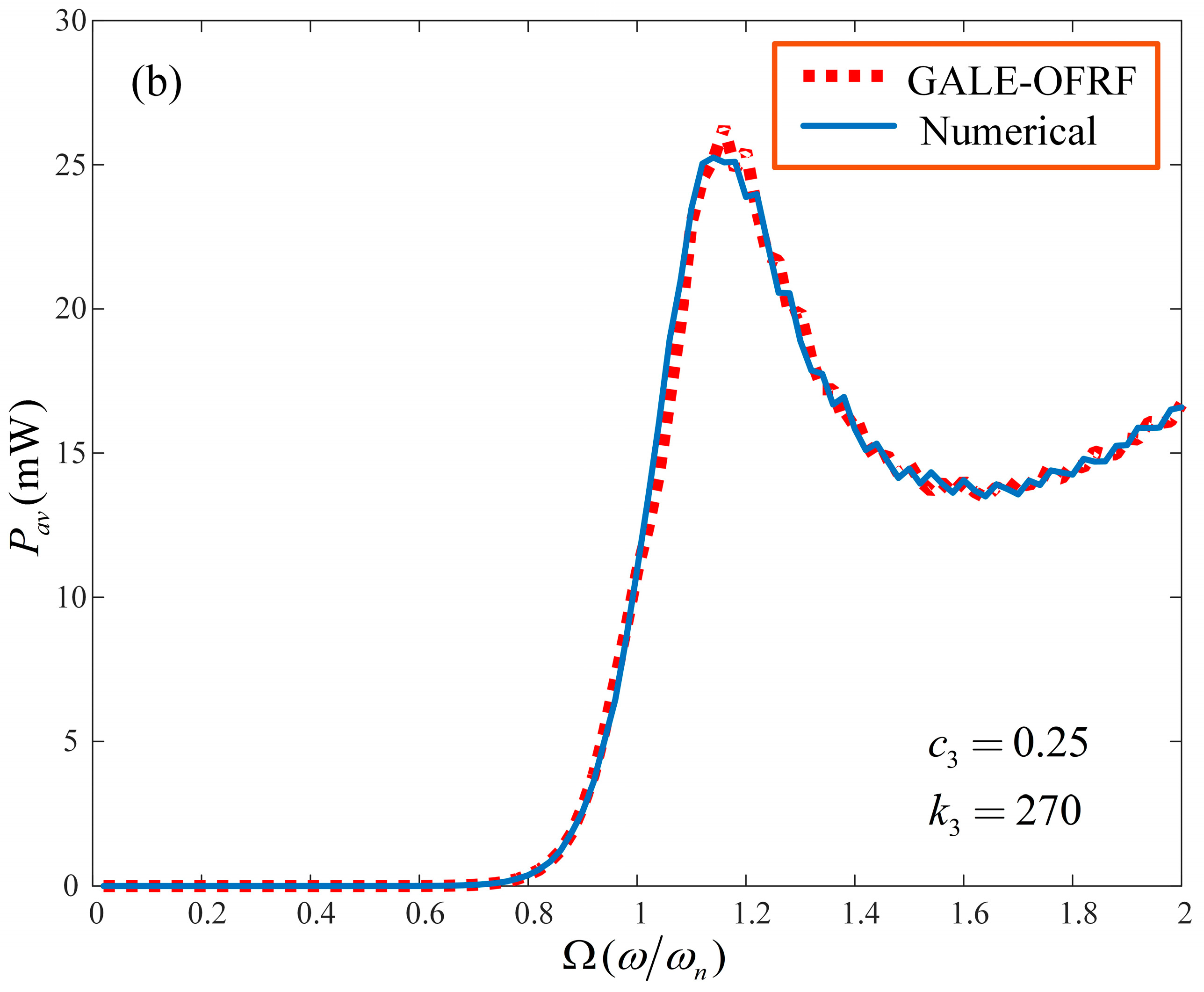
−3, respectively. In the next section, the results obtained from the GALE-generated OFRF representations, presented in Equations (24) and (27), are provided and their implications discussed extensively.
7. Results and Discussion
The OFRF representation of the output spectrum,
, of system (2) was derived using the GALE decompositions evaluated from the same system. The OFRF representation of the output spectrum was subsequently used to estimate the average power generated by the electromagnetic damper. This was performed for a pair of nonlinear parameter values,
and
, beyond the range over which the OFRF representation was determined, i.e.,
Ns
3m
−3 and
Nm
−3. As observed in
Figure 6 and
Figure 7, the OFRF representation accurately represents the actual output spectrum and average power of the VEH, respectively. These results clearly demonstrate a good match between the OFRF representation and the more accurate results from direct numerical simulations. This demonstrates the benefits of the OFRF methodology as it evidently describes the system dynamics over the entire spectrum. Note that the wobbles observed around the resonant regions in
Figure 6 and
Figure 7 are due to the use of parameters beyond the design (training) range. Using parameters further beyond the design range will cause the system to approach instability.
In the implementation of such a nonlinear VEH system, the cubic damping nonlinearity can be contributed by an electromagnetic damper whose characteristics are dependent on that of the load resistance of the energy-harvesting circuit. The hardening stiffness nonlinearity can be realised by the application of magnetic springs, wherein a mass of permanent magnet is levitated between two stationary magnets [
38]. However, such magnetic springs can also contribute a damping component typically referred to as magnetic damping [
39].
7.1. Effect of a Hardening Spring and Cubic Damping on the VEH System
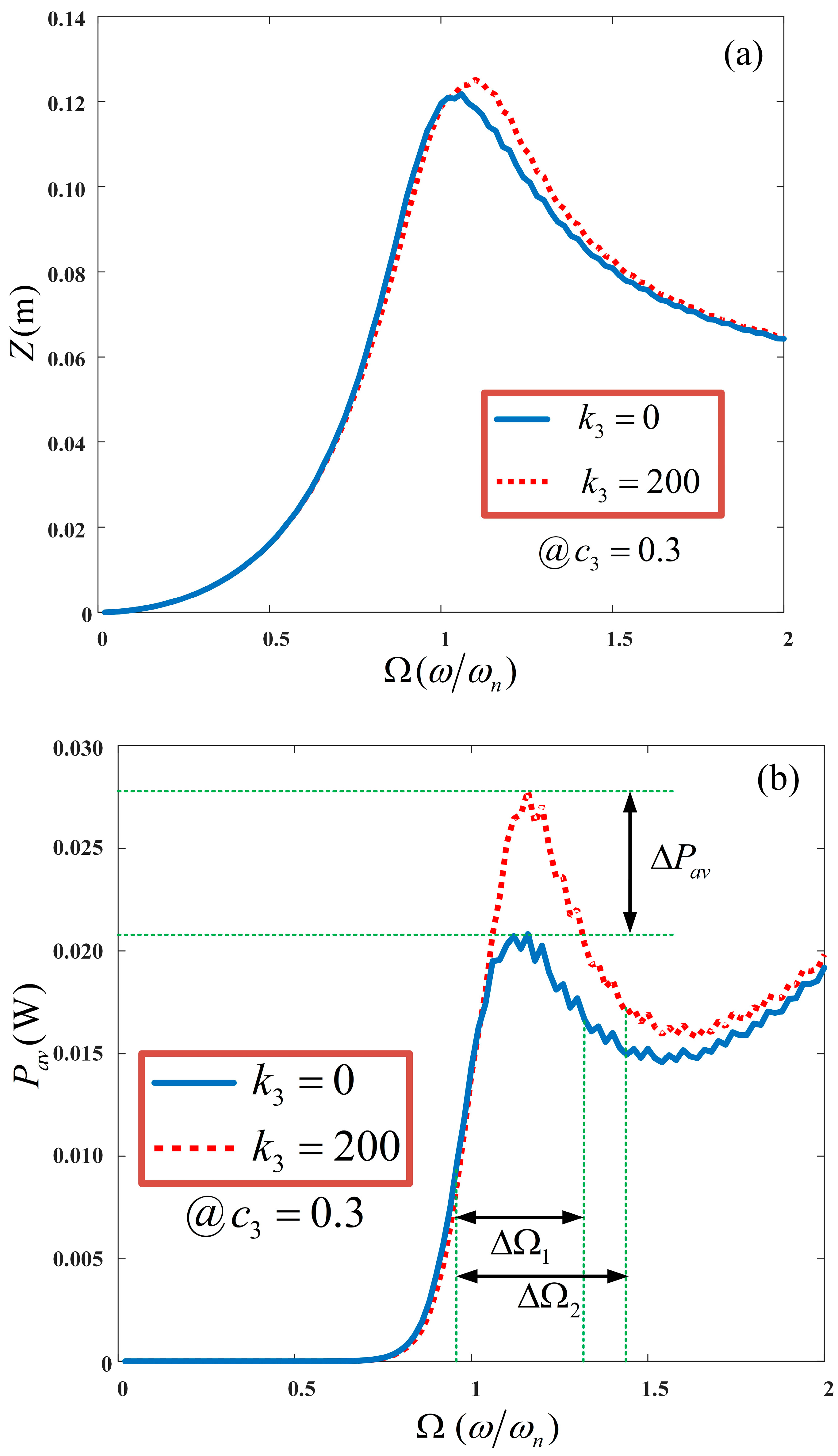
Nonlinearities contributed by a hardening-type spring stiffness is integrated into a standard linear harvesting device to expand the bandwidth over which power can be harvested. The bandwidth expansion is caused by a shift in the resonant frequency to higher frequencies. To demonstrate the effect of integrating a hardening-type stiffness characteristic into the dynamics of a VEH system with cubic damping nonlinearity, numerical studies were conducted. The integration of a hardening spring effect can be implemented by employing magnetic springs [
38]. Using the OFRF representations provided in Equations (24) and (25), the effect of the stiffness parameter,
can be observed in
Figure 8. It is clearly seen to extend the operational bandwidth of the nonlinear VEH system due to the shift in the resonant frequency of the output spectra. The operational bandwidth of the VEH system, with and without a nonlinear stiffness characteristic, are denoted as
= 0.636 Hz and
= 0.516 Hz, respectively. In addition to this, an apparent 35.71% increase in the dynamic range of the nonlinear VEH system can also be observed; that is, from 0.021 mW to 0.0285 mW. This is logical as the average power of the nonlinear VEH system, given in Equation (25), is a function of the excitation frequency,
. Several studies in the literature focused on increasing the bandwidth of linear VEH devices with the integration of a hardening-type stiffness and compared the Duffing-type harvester with a standard linear harvester.
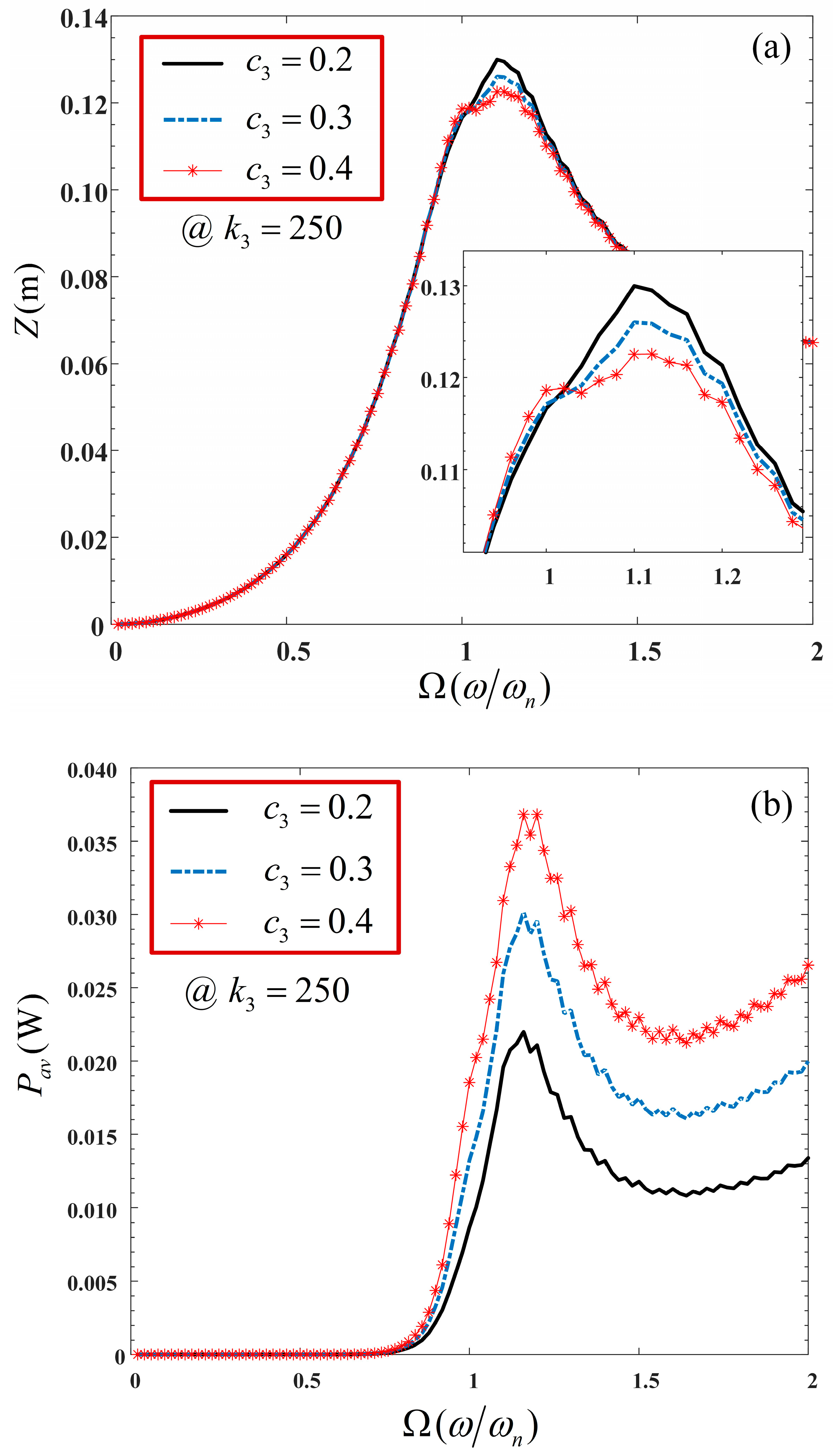
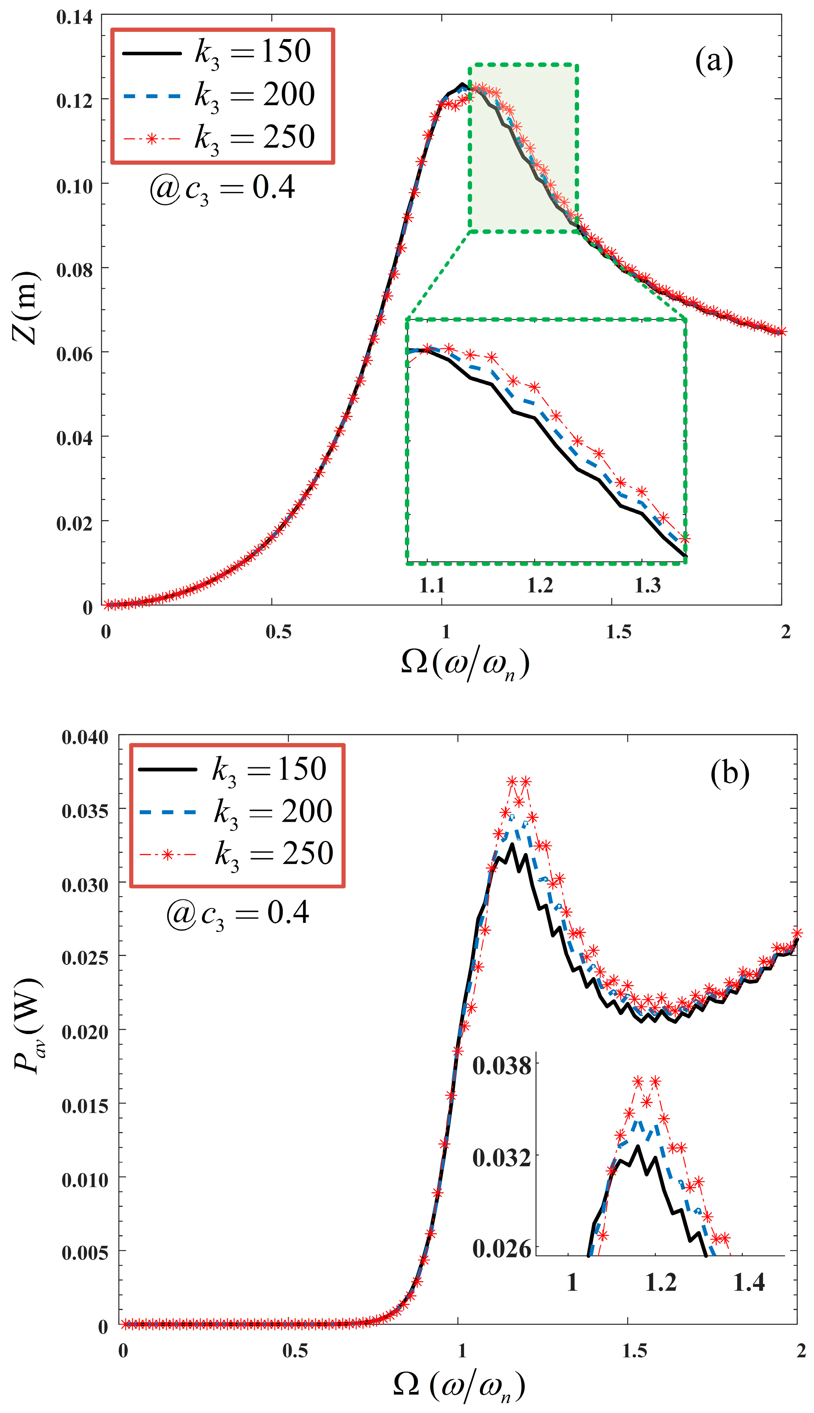
Figure 9 shows the effect of varying the nonlinear stiffness characteristics on the output spectrum and average power of the nonlinear VEH system. In
Figure 9a, while the relative displacement of the VEH system remains relatively constant as
increases, it is evident, in
Figure 9b, that the average power of the VEH device increases within the resonant region,
, as
increases. However, the power remains relatively constant within the low- and high-frequency regions, where
and
, respectively.
Furthermore, the effect of a variation in the nonlinear cubic damping,
, on the VEH system was also investigated. This was demonstrated by varying
while fixing
, as shown in
Figure 10. It is revealed that while the maximum span of the VEH system reduces by an insignificant amount, the average power harvested increases significantly around and beyond the resonant region. It should be noted that to implement the nonlinear cubic damping force characteristics, the current flowing through the nonlinear load (energy-harvesting circuit) should be proportional to the cube of the voltage across it [
21].
In the current study, a hardening-type stiffness is integrated in a VEH system with cubic damping nonlinearity. However, a comparison of the VEH with damping and stiffness nonlinearities against its linear equivalent has not been considered here. This is due to the unavailability of a basis for such comparison to be made. Comparisons of this nature have never been reported for electromagnetic-type VEH devices with damping and stiffness nonlinearities to the best of the authors’ knowledge.
Furthermore, most studies in the literature considered the Duffing-type harvesters that exhibit the jump phenomenon, and they were primarily designed to operate within the larger stable branch. Nevertheless, it is imperative to note that if the VEH model experiences a jump phenomenon, the sum of the GALE decompositions will not converge to the actual output spectrum around the jump region. Therefore, the OFRF representations will poorly describe the actual output spectra of the system and, consequently, will be an inappropriate method to conduct the system analysis and design. However, this problem is resolved here with the integration of both linear and nonlinear damping characteristics.
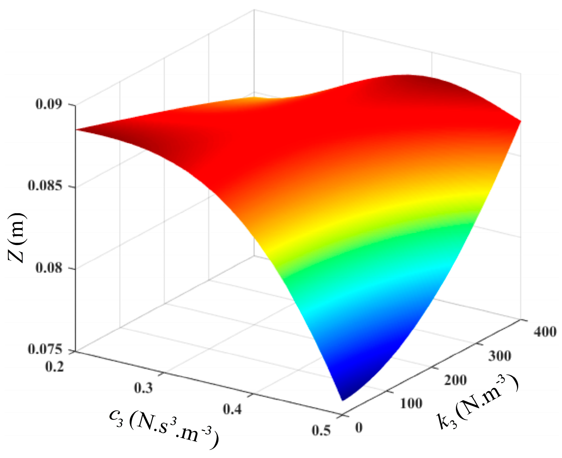
7.2. Optimisation of an Unconstrained Nonlinear VEH System
Using the OFRF representation of the average power as determined in Equation (27), an optimisation problem can be formulated as
The solution to the unconstrained optimisation problem is simple and can be determined using the MATLAB
fminsearch or
fmincon functions. Moreover, using the OFRF representations of Equations (24) and (27), the relationships between the design parameters,
,
, the output spectrum, and the average power at the resonant frequency can be established. These are presented using surface plots in
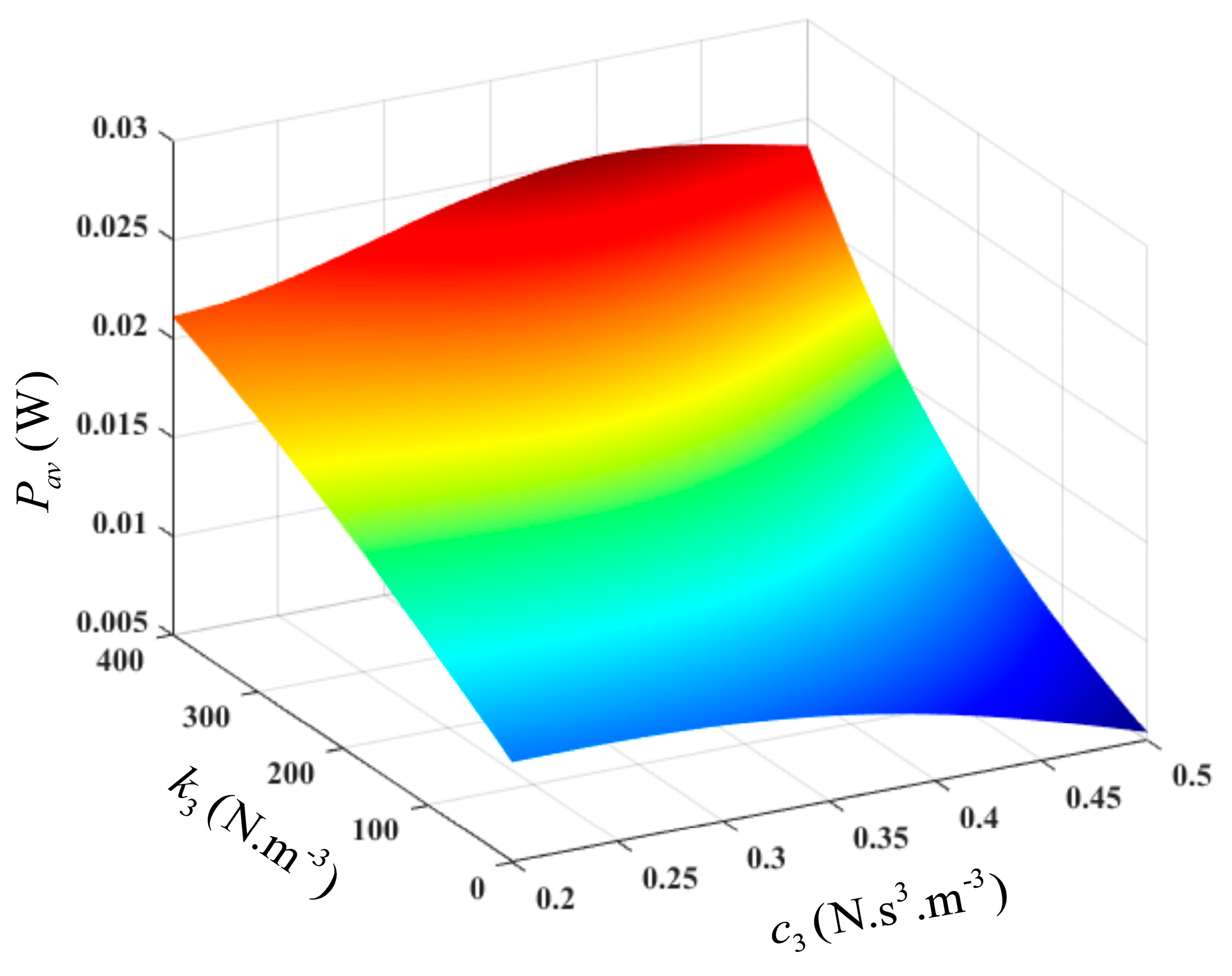
Figure 11 and
Figure 12. It can be deduced from
Figure 12 that the average power is significantly sensitive to the nonlinear stiffness characteristic,
, but less sensitive to the nonlinear damping characteristic,
, at lower values of
. However, at higher values of
, the average power increases to an optimal value as
increases to 0.46, then it starts to decline. It should be noted that this design is only valid within the design range of the parameters of interest.
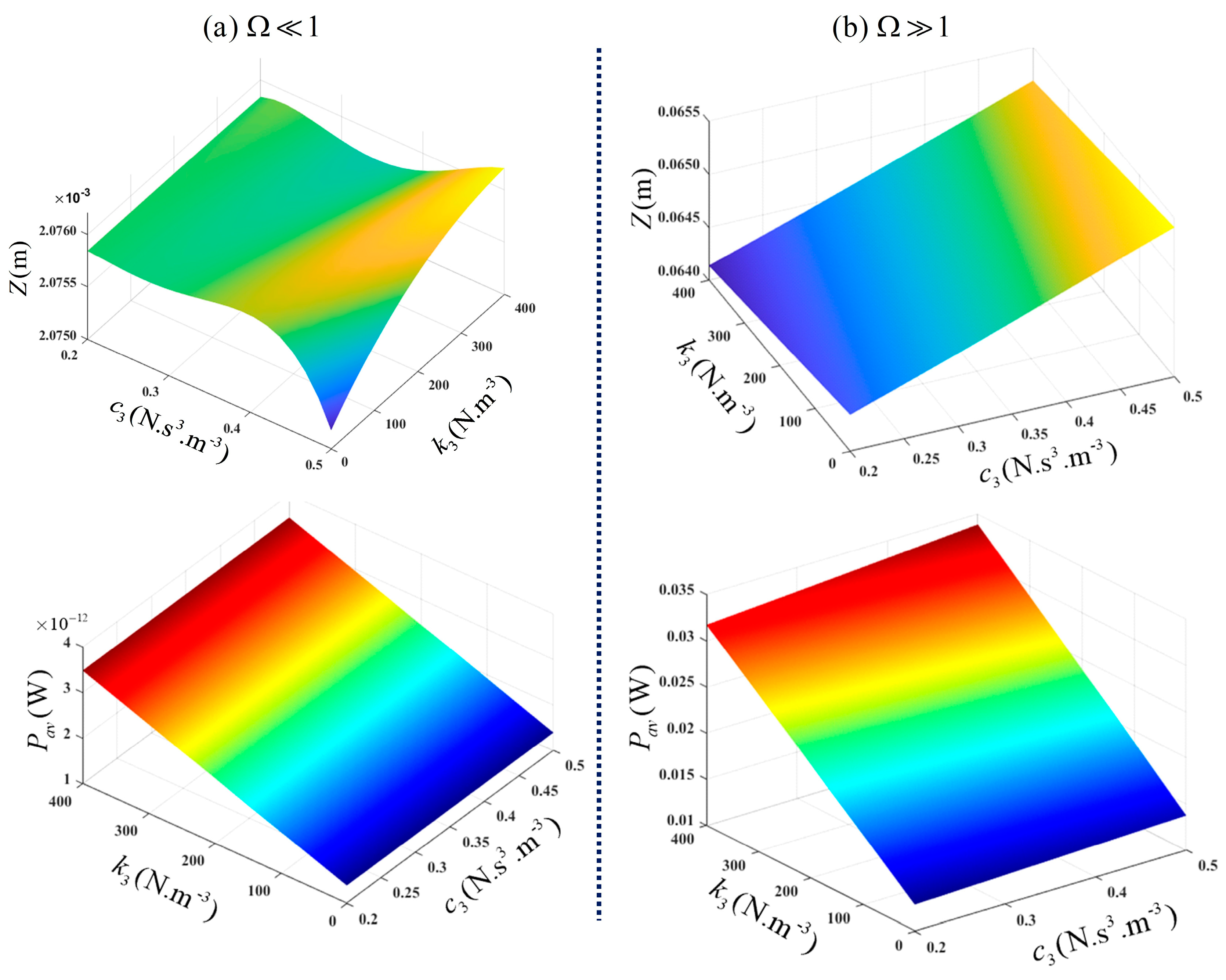
In
Figure 13, the output spectrum and average power of the VEH system, for a variation in
and
, are provided at
and
, respectively.
8. Conclusions
In this study, the analysis and design of a vibration energy harvester with damping and stiffness nonlinearities were considered. Nonlinear stiffness was introduced into the mechanical subsystem of the vibration energy harvester to extend the operational bandwidth of the VEH system. In addition, the nonlinear damping, which is a function of the nonlinear load in the energy harvesting circuit, is able to extend the average power of the VEH system. It should be noted that the dynamic characteristics of the energy harvesting circuit influence the damping characteristics of the nonlinear electromagnetic damper, as shown in
Figure 2.
The Output Frequency Response Function (OFRF) polynomial representation of the actual system model (2) was determined using the Generalised Associated Linear Equation (GALE) decompositions of the system. By using the GALE method, the number of numerical simulations needed to determine the OFRF polynomial representation of the actual system was considerably reduced. Subsequently, the GALE-generated OFRF representation of the actual system was validated numerically to ensure it clearly described the system output spectra.
The effect of a hardening stiffness nonlinearity, as well as a nonlinear cubic damping, on the VEH system was investigated. The application of low-level excitations for this study ensured no jump phenomenon was exhibited. This is because the GALE and OFRF concepts are applicable only to a class of nonlinear systems stable at zero equilibrium and which can be described by a Volterra series model. The exhibition of a jump by the system model will nullify the suitability of the methods employed in this study.
The results obtained in this study show that the nonlinear stiffness characteristic extended the operational bandwidth by 23.26%. In addition, the harvested power was also increased by 35.71%, hence improving the performance of the VEH system. It was also revealed that employing a nonlinear cubic damping characteristic, in the presence of a nonlinear stiffness characteristic, improved the performance of the VEH system. Using the GALE-generated OFRF representation, optimal values of the VEH design parameters can be determined for any desired power level within and beyond the design range. Future studies will focus on the design of VEH systems with damping and stiffness nonlinearities subject to mass-displacement constraints inherent in practical VEH systems.
A prototype of the proposed system model is currently being fabricated in order to conduct some experimental studies. This is a follow-up to the current study and is expected to be used to validate the method employed herein. While the nonlinear stiffness can be realised using magnetic springs or geometrical nonlinear springs, the nonlinear damping could be realised using an energy-harvesting circuit with a nonlinear characteristic load. Such an energy-harvesting circuit will provide a current which varies proportionally with the cubic power of the voltage. The proposed nonlinear load could be designed using power electronics methods, such as a DC-DC switching converter.


