Article

A Novel Planning and Tracking Approach for Mobile Robotic Arm in Obstacle Environment

1
School of Computer and Artificial Intelligence, Beijing Technology and Business University, Beijing 100048, China
2
Beijing Laboratory for Intelligent Environmental Protection, Beijing Technology and Business University, Beijing 100048, China
3
China Food Flavor and Nutrition Health Innovation Center, Beijing Technology and Business University, Beijing 100048, China
4
School of Arts and Sciences, Beijing Institute of Fashion Technology, Beijing 100029, China
*
Author to whom correspondence should be addressed.
Machines 2024, 12(1), 19; https://doi.org/10.3390/machines12010019
Submission received: 24 October 2023 / Revised: 24 December 2023 / Accepted: 27 December 2023 / Published: 29 December 2023

Abstract

:
In this study, a novel planning and tracking approach is proposed for a mobile robotic arm to grab objects in an obstacle environment. First, we developed an improved APF-RRT* algorithm for the motion planning of a mobile robotic arm. This algorithm optimizes the selection of random tree nodes and smoothing the path. The invalid branch and the planning time are decreased by the artificial potential field, which is determined by the specific characteristics of obstacles. Second, a Fuzzy-DDPG-PID controller is established for the mobile robotic arm to track the planned path. The parameters of the PID controller are set using the new DDPG algorithm, which integrated FNN. The response speed and control accuracy of the controller are enhanced. The error and time of tracking of the mobile robotic arm are decreased. The experiment results verify that the proposed approach has good planning and tracking results, high speed and accuracy, and strong robustness. To avoid the occasionality of the experiments and fully illustrate the effectiveness and generality of the proposed approach, the experiments are repeated multiple times. The experiment results demonstrate the effectiveness of the proposed approach. It outperforms existing planning and tracking approaches.

1. Introduction

With the development of science and technology, mobile robotic arms have become a hot topic in the robotic research community. According to the information on the target object and environment acquired by sensors, the mobile robotic arm can autonomously grab the object, so they are widely used in many domains [1,2]. The grabbing task of a mobile robotic arm depends on two functions. First, the robotic arm plans the motion path for grabbing the object [3]; second, the robotic arm utilizes the controller to track the planned path [4]. However, there are many obstacles and environmental disturbances around the mobile robotic arm in the real-world environment. These factors have a certain impact on the performance of planning and tracking [5]. Therefore, it is very important to propose a novel planning and tracking approach for mobile robotic arms to grab objects in obstacle environments.
Many algorithms have been presented for the motion planning of robotic arms. These algorithms mainly include Dijkstra [6], A* [7], Artificial Potential Field (APF) [8], PRM [9], and RRT [10]. The RRT has simple and flexible structures, and it has been popularly used for path planning in robotic fields. It also has many variants [11,12]. Based on the RRT, the RRT* introduces the notion of cost. As the sampled waypoints approach infinity, their path converges to the optimal solution with the least cost [13]. However, slow planning speed and many invalid branches are also realized. To solve these problems, Gammell et al. [14] developed the informed-RRT*. It limits the search area in an ellipsoidal subset of the state space, and it can accelerate the search for the optimal path. Chi et al. [15] provide the Risk-RRT*. The quality of paths is improved by utilizing the RRT* in a time-based framework. The velocity of the two algorithms above is accelerated, and the length of paths is decreased. However, there are many turning points in paths when working in areas of obstacles. Yuan et al. [16] propose an APF-RRT algorithm for the motion planning of robotic arms. It introduces a heuristic method based on the number of adjacent obstacles to escape from local minima. It adopts an adaptive step, generates a virtual new node strategy to explore the path, and removes redundant path nodes. Jiang et al. [17] combine the RRT with the APF for path cutting and optimization. The planned path is short and smooth, and the success rate of planning is improved. The two APF-RRT algorithms above decrease path distance and planning time. Nevertheless, the shape and position of different obstacles are not considered; thus, many invalid branches are generated in paths.
Mobile robotic arms generally utilize proportional integral derivative (PID) controllers [18] for tracking the planned path. However, especially in obstacle environments, the presence of environmental disturbance can cause a low response speed and large errors in tracking [19,20,21,22,23]. To enhance the adaptability of tracking, the fuzzy neural network (FNN) [24] is also widely used for tracking robotic arms. In [25], a sliding mode control (SMC) method is associated with the FNN to constitute a robust control scheme to cope with the tracking error caused by environmental disturbance. Du et al. [26] use the self-feedback incremental FNN to predict and update the compensation in real-time. The deviation distance caused by environmental disturbance is reduced. Mai et al. [27] developed an intelligence PID controller. In this controller, an adaptive FNN approximator and an adaptive robust compensator are utilized to reduce the uncertainties of the system. The three FNN controllers above reduce tracking errors, but the response speed is not accelerated effectively. With the deep reinforcement learning (DRL) [28] technology developing, the DRL algorithm, such as deep Q-network (DQN) [29] and deep deterministic policy gradient (DDPG) [30], is utilized for real-time tracking of the robotic arm. Wang et al. [31] designed a DQN-based PID (DQN-PID) controller. This controller is employed for image-based visual servo (IBVS) control. It also solves the problem of feature loss and large steady-state error and improves the servo accuracy of mobile robotic arms. To further enhance the performance of grabbing robotic arms, Geng et al. [32] propose an improved DDPG algorithm based on fractional-order control. It enhances the accuracy and adaptability of tracking robotic arms using environmental dynamics modeling and grab posture optimization. Afzali et al. [33] present a new modified convergence DDPG (MCDDPG) controller to control robotic arms with high DOF. It shows a significant enhancement in training time and stability of the control. The three controllers above improve accuracy and speed of tracking, whereas poor robustness is also achieved.
To solve the problems mentioned above, we propose a novel planning and tracking approach for mobile robotic arms to grab objects in obstacle environments. First, we develop an improved APF-RRT* algorithm for motion planning of the mobile robotic arm. It optimizes the process of expanding random trees, and the path is simplified via APF. Second, a Fuzzy-DDPG-PID controller is established for tracking control of the mobile robotic arm. We develop a new DDPG algorithm in which the update function and loss function are improved, and the FNN with the optimized fuzzy rules is integrated. The Fuzzy-DDPG is utilized for tuning the parameters of the PID controller.
The detailed contributions of this approach are as follows:
(1)
An improved APF-RRT* algorithm is developed. First, for RRT*, the node selection process is optimized, and the Dubins curve is used to smooth the path. The total turning angle is reduced while decreasing the path length. Second, an APF is used to generate artificial potential fields according to the shape and position of obstacles and keep the random tree away from the obstacles. Therefore, the invalid path branches are reduced, and the speed of planning is accelerated;
(2)
A Fuzzy-DDPG-PID controller is established. To promote the adaptiveness of path tracking of the robotic arm in an environment with disturbance, a Fuzzy-DDPG algorithm is integrated with the PID controller. First, to solve the problem of slow disturbance capture in DDPG, the update function and loss function are improved, and the policy-making speed is accelerated. Second, a FNN is proposed to solve the problem of the strong subjectivity of the DDPG online network. The membership function and fuzzy rules of FNN are optimized, and the online network of DDPG can be updated in real-time. Therefore, the response speed and policy-making accuracy are enhanced. By combining the Fuzzy-DDPG with the PID controller, the tracking time, time delay, and error of tracking are reduced. The robustness is enhanced.
The rest of the contributions of this study are organized as follows: we introduce the experimental platform in Section 2. Section 3 focuses on the technical details of the proposed approach. We compare and analyze the proposed approach with different approaches in Section 4. Finally, the works of this study are summarized in Section 5.

2. The Experimental Platform

The experimental platform called Turtlebot3-ARM is a 5-degree-of-freedom (DOF) mobile robotic arm. It is generally composed of a mobile platform, a robotic arm, a LiDAR, RGB-D cameras, and stepping motors. The robotic arm has five joints, and each joint is equipped with a motor. For the robotic arm, there is a motor between the mobile platform and the robotic arm, which is employed to control the horizontal rotation of the robotic arm. There is a motor at the bottom, middle, and top joint of the robotic arm, respectively. The three motors are utilized for stretching and retrieving the robotic arm. There is a motor at the gripper, and it is leveraged for gripping and loosening the target object. The processor frequency of Turtlebot3-ARM is 1.43 GHz, the RAM is 4 GB, and the ROM is 64 GB. Its operating system is called the robot operating system (ROS), and it is built on Ubuntu 16.04. The parameters of Turtlebot3-ARM are shown in Table 1. The robotic arm part of Turtlebot3-ARM is shown in Figure 1a, where yellow fonts denote the positions of the joints. The coordinate system of the robotic arm joint is presented in Figure 1b.
According to the kinematics analysis description of the robotic arm in [34], the kinematic equation of the 5-DOF robotic arm we applied is as follows:
M ( q ) q + C ( q , q ) q + g ( q ) = F ,
where q = [ q 1 , q 2 , q 3 , q 4 , q 5 ] is the 5 × 1 vector of joint displacement, q i = ( x i , y i , z i ) R 3 ,   i [ 1 , 5 ] . R 3 is the coordinate set of feasible area in the environment. q is the 5 × 1 vector of joint velocity, q is the 5 × 1 vector of joint acceleration, F is the 5 × 1 vector of the motor torque, M ( q ) is the 5 × 5 symmetric positive definite inertia matrix of robotic arm, C ( q , q ) is the 5 × 5 matrix of centripetal and Coriolis torques, and g ( q ) is the 5 × 1 vector of gravitational torques. The kinematics of the robotic arm mainly has three properties:
Property 1, the C ( q , q ) and the M ( q ) satisfy the following relationship:
( q ) T [ 1 2 M ( q ) C ( q , q ) ] q = 0 ,
M ( q ) = C ( q , q ) + C ( q , q ) T .
Property 2, there exists a positive constant k g , such that:
g ( q ) q k g .
Property 3, there exists a positive constant k c , such that:
C ( x i , y i ) z i k c y i z i , i [ 1 , 5 ] .
After obtaining the dynamic matrix through the DDPG, k g and k c can be obtained using the following formula:
k g = 5 ( max i | g ( q i ) q i | ) ,
k c = 25 ( max i , k | C k ( q i ) | ) ,
where C k ( q i ) is the matrix of joint displacement torque.

3. The Proposed Approach

3.1. Planning Based on the Improved APF-RRT*

We develop an improved APF-RRT* algorithm as shown in Algorithm. First, in RRT*, the node-selecting process is optimized, and the Dubins curve [35] is applied to smooth the path. The path length and the total turning angle are reduced. Second, APF is combined with RRT*. It can generate artificial potential fields according to the shape and position of obstacles and keep the random tree away from the obstacles. The invalid and redundant path branches are cut, and the speed of planning is accelerated as well. The entire grabbing task of the robotic arm includes a stretching and retrieving process; we consider the two processes as one model to analyze the planning.

3.1.1. The Improved RRT*

For RRT*, our works are as follows:
As shown in Figure 2a, The random tree does not expand until the new nodes q n e w are firmed. The current state of the random tree is T , and q c = ( X , Y , Z ) represents the center coordinate of the current state of the robotic arm joints.
When q n e w has been firmed, the selection circle of q p a r e n t is formulated based on the boundary point coordinates of the obstacle. The parent node q p a r e n t and its nearest nodes are searched in this circle, and the radius of this circle is R . The process is shown in Figure 2b; the node set D for the candidate q p a r e n t are as follows:
D = { q i | | q i q m | = R < l 0.03 } ,   i = 1 , 2 , , N ,
where q i ( i = 1 , 2 , , N ) is the candidate parent node in D , q m is the center node of D . To ensure the effect of obstacle avoidance, l is the distance between the two edge points of obstacles.
According to the difference in cost and steering angles of nodes in D , the Dubins curves are used to separate high-cost nodes in the forms of circles with different radii. The low-cost nodes are connected and smoothed simultaneously. This step is shown in Figure 2c. After this step, the coordinate of the new random tree state for five robotic arm joints is confirmed. The center point C k and radius r k of separating circle is as follows:
C k = { 1 5 j = 1 5 q j , 0 q j 1 q j 2 < 30 1 5 j = 1 5 q j + q n e w | q j 1 q j 2 | min sin ( θ min 2 ) , q j 1 q j 2 30 ,
r k = | q j 1 q j 2 | max + 0.02 ,
where q j ( j [ 1 , 5 ] ) is the candidate node for joints of robotic arm, θ ( q j 1 , q j 2 ) is inclination angle between two nodes of q j . If 0 q j 1 q j 2 < 30 , the nodes unseparated on circle C k can be connected without smoothing, else they need to be smoothed. | q j 1 q j 2 | min is the minimum distance between two nodes of q j , θ min is the minimum inclination angle between two nodes of q j , and | q j 1 q j 2 | max is the maximum distance between two nodes of q j .
After separation, according to the principle of path cost calculation of the D*Lite algorithm [35], a path cost function is utilized to calculate the minimum cost of the remaining nodes. Thereby, the nodes that meet the minimum cost are connected as a new random tree state T . This step is shown in Figure 2d, and the path cost function is as follows:
c = 2 × min ( | X X | , | Y Y | , | Z Z | ) + 1 5 | X X | ,
where q c = ( X , Y , Z ) represent the center coordinate of a new state of the robotic arm joints.

3.1.2. Addition of APF

Based on the improved RRT*, we merged the APF to make the path as if entering an expanded obstacle area. The specific works of APF are as follows:
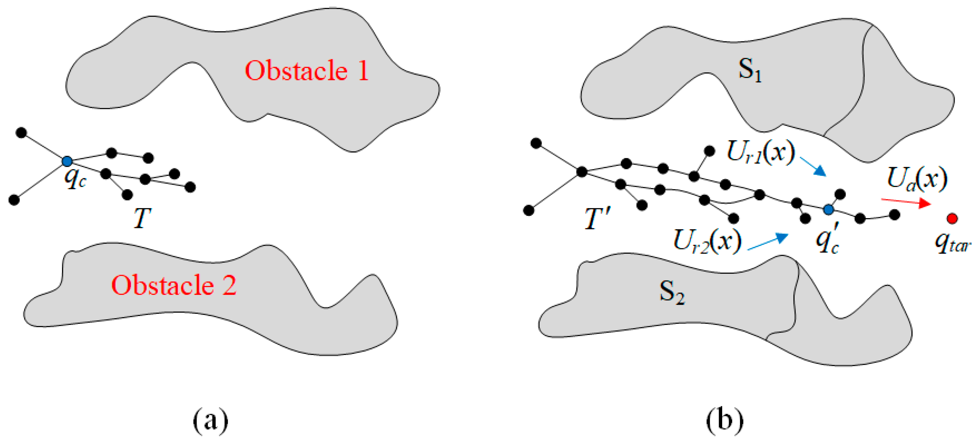
As shown in Figure 3a, there is no artificial potential field in the environment until the robotic arm starts stretching or retrieving. When the state of the random tree has changed, a repulsive potential field U r i ( i = 1 , 2 , ) is generated by the zone of obstacle i behind q n e w , as shown in Figure 3b. The gravitational potential field U a is generated by the target object or robotic arm base. The potential field equations are as follows:
U a = d t a r k 1 ρ ( q n e w , q t a r ) 1 2 k 0 d t a r 2 ,
U r i = 1 2 μ i ( 1 ρ ( q n e w , q c i ) 1 ρ ( q c i ) ) ,
where d t a r is the threshold of the gravitational potential field, q t a r is the coordinate of the target object or robotic arm base. k 0 is the invariable gravitational gain constant, k 1 is the variable gravitational gain constant, μ i is the repulsive gain constant, q c i is the center point of the passed zone in the obstacle i , ρ ( q n e w , q c i ) represents the distance vector from q n e w to q c i , and ρ ( q c i ) represents the influence range of the obstacle i . As the random tree expands, U a and U r i will also change, and they are decided by k 1 and μ i respectively. k 1 and μ i are represented as follows:
k 1 = k 0 i = 1 n S i i = 1 n | q c i q f i | ,
μ i = S i q c i q n i ,
where S i ,   i [ 1 , 2 ] is the area of the zone that the random tree has passed through in obstacle i , and S i is observed by the RGB-D camera on the robotic arm. q f i is the farthest point from q c i in S i , and q n i is the closest point from q c i in S i .
Algorithm: Improved APF-RRT*
Input: Process (stretch, retrieve), obstacle area Si, current state T
Output: Path(T, qnew, qmin)
Step 1:V ← qi;
Step 2:i ← 0;
Step 3:Motion ← Process(stretch, retrieve)
Step 4:For i = 1:N do
Step 5:   qrand ← Sample(qinit, T);
Step 6:   i ← i +1;
Step 7:   qnearest ← Nearest(qrand);
Step 8:   qnew ← Steer(qnearest, qtar);
Step 9:   if CollisionFree(qnearest, qnew, Si) then
Step 10:      qnearest ← Nearest(qnew, D);
Step 11:      qparent ← Parent(qnearest, Rk);
Step 12:   For j = 1:M do
Step 13:      if ExcludeDubinsCircle(qnew) then
Step 14:         qnew ← PlanNode(qparent, Ua, Ur);
Step 15:         Cost(qmin) = Cost(qnearest) + Cost(qnew, d);
Step 16:      T’ ← Path(T, qnew, qmin);
Step 17:   Return T’;

3.2. Tracking Based on the Fuzzy-DDPG-PID

A Fuzzy-DDPG-PID controller is established in this study. It can tune the parameters of PID and reduce tracking errors. As shown in Figure 4, where ω is the angular velocity vector of the motor, ψ ( ω ) is the input variable, ψ ( ω ) is the output variable, c ( ω ) is the control instruction output by the PID controller, d ( ω ) is the disturbance function, K p is the proportional parameter, K i is the integral parameter, and K d is the differential parameter.
For the Fuzzy-DDPG algorithm, our work mainly includes two parts. First, for the DDPG, the update function and loss function are improved to accelerate the policy-making speed of tracking control. Second, the membership function and fuzzy rules of FNN are optimized. The FNN is utilized to update the DDPG’s online network in real-time. Therefore, the response speed and control accuracy of the controller are enhanced.

3.2.1. DDPG Algorithm

The DDPG can analyze the states of the system via the Actor–Critic construction and then make policies to determine the parameters of PID. For the DDPG, our specific works are as follows:
In DDPG, the robotic arm states that T and T are important factors. They are utilized for determining the action of the mobile robotic arm, and they are functions of the robotic arm joint coordinates q i ,   i [ 1 , 5 ] . The DDPG we proposed is shown in Figure 5.
In the online Actor network, we have considered the rewards r from T to T . The r is executed and acquired by action a . The a is the function of M ( q ) , C ( q , q ) and g ( q ) in Equation (1), and the r is the function of q in Equation (1). The update function μ ( T ; θ μ ) of the environmental state, which is based on the gradient-rise method, is used as follows:
θ J = E s [ a Q ( T , r , a ; θ Q ) × θ μ ( T ; θ μ ) ] ,
where E s is the parameter selection function to minimize network error. θ μ and θ Q are the parameters of the online Actor network and the Critic network, respectively, and Q is the value function acquired in the online Critic network.
In the online Critic network, the evaluation of the T is fully considered, and the gradient of the online Critic network is as follows:
θ Q = E [ ( r + θ γ Q ( T , T , μ ( T ; θ μ ) ) Q ( T , a ; θ Q ) ) × θ Q ( T , T , a ; θ Q ) ] ,
where μ is the new environmental state from the target Actor network. Q is the value function acquired in the target Critic network, and it is utilized to determine the parameters of the PID controller. θ μ and θ Q are the parameters of the target Actor network and Critic network, respectively, and γ ( 0 , 1 ) is the parameter of the target Critic network.
We improve the loss function of DDPG based on the updated results of FNN; the loss function L ( θ f ) is as follows:
L ( θ f ) = 1 N i [ α F ( T , T ; θ c ) ( 1 α ) μ ( T , r ; θ μ ) ] 2 ,
where θ f is the Critic network parameter selected by fuzzy rules, F is the value function of the Critic network calculated using DDPG and FNN, and α ( 0 , 1 ) is the loss parameter.

3.2.2. The Addition of FNN

DDPG needs to determine the next state of the mobile robotic arm according to expert experience. However, due to the state transformation of the environment not being considered, the response speed is slow, and environmental parameters are difficult to obtain in DDPG. Therefore, we added FNN to provide updated parameters for the online network of DDPG in real time.
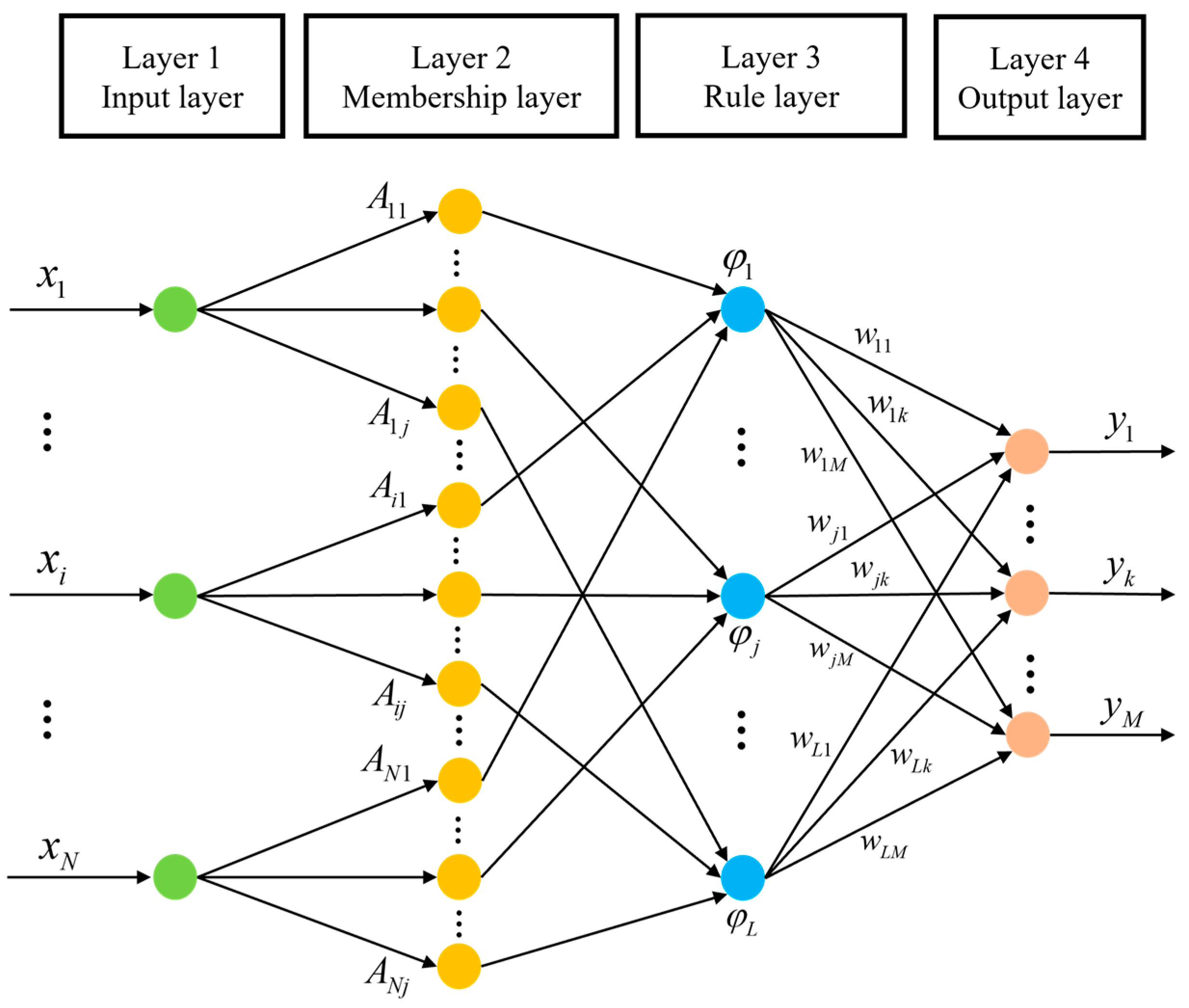
As shown in Figure 6, FNN consists of four layers. The first layer is the input layer, whose nodes correspond to input variables x i , i [ 1 , N ] . After this layer, x i , i [ 1 , N ] are converted to fuzzy variables. The second layer is the membership layer, and its corresponding function A i j is employed to quantify the dimension of membership for input variables. The third layer is the fuzzy rule layer. φ j ,   j = 1 , 2 , , L represents the truth value of rules. w j k is the weight of the consequent part. The last layer is the output layer. Its nodes correspond to output variables y i ,   i [ 1 , M ] . In this study, the input variable x is μ ( T ; θ μ ) , and the output variable y is the update function μ ( T ; θ μ ) integrated into the kinematical equation of Equation (1).
For FNN in this study, we consider the state transformation of the environment, the membership function, and the fuzzy rule, which are optimized to make the update parameters of the DDPG online network provided by FNN more accurate. Thereby, the response speed and control accuracy are improved. The equations of the improved membership function A i j ( x i ) and fuzzy rule φ j ( x i ) are as follows:
A i j ( x i ) = exp [ ( x i c i j c ¯ ) 2 σ i j 2 ] ,
φ j ( x i ) = A i j ( x i ) × j 2 × k ,
where c i j and c ¯ are the center and average values of A i j ( x i ) respectively.

4. Experiments and Analysis

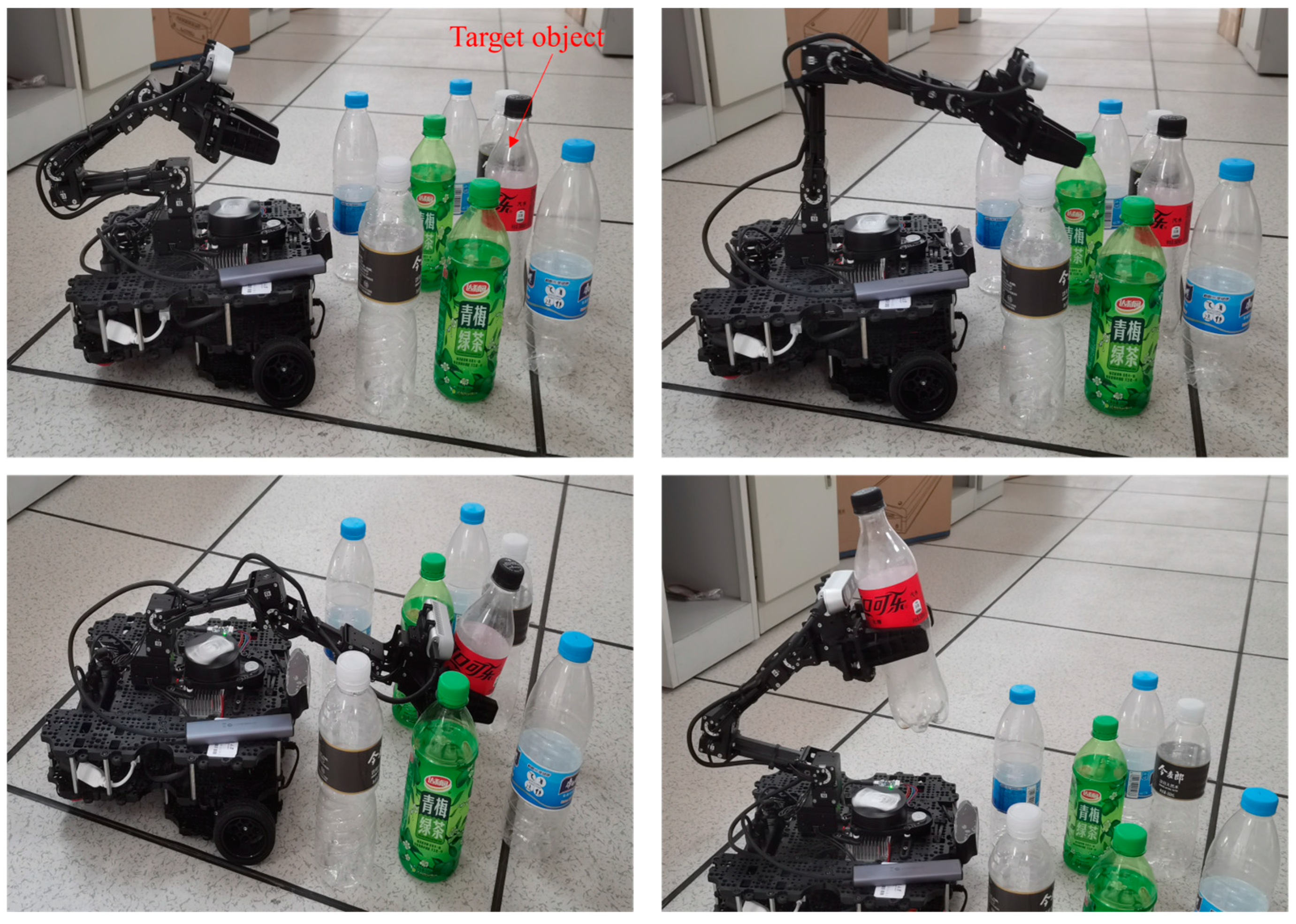
To demonstrate the effectiveness of the proposed approach, we conduct real-world object-grabbing experiments of the mobile robotic arm in an obstacle environment. We place some bottles as obstacles in a real-world environment, and one of these bottles is used as the target object to be grabbed. As shown in Figure 7, the information on the obstacle environment and target object are acquired via the RGB-D camera of the mobile robotic arm, and then the grabbing task of the mobile robotic arm is performed. The entire grabbing task can be divided into the stretching and retrieving process. The algorithm and control module of this robotic arm are realized based on the MoveIt development platform, in which the real-time states of the robotic arm are also acquired, as shown in Figure 8. We present the experimental results of motion planning and tracking control for the entire grabbing task, and the performance of the proposed approach is compared with other approaches, as shown in Section 4.1 and Section 4.2.

4.1. Experiments and Analysis of Planning

To verify the availability of the improved APF-RRT* in motion planning, we make planning comparisons of four different algorithms. Algorithm 1 represents the traditional RRT*, Algorithm 2 denotes the improved RRT* in Section 3.1.1, Algorithm 3 combines the traditional APF with Algorithm 2, and Algorithm 4 is the improved APF-RRT* proposed in this study. The coordinates of the robotic arm base are set as (−0.135, −0.147), and the coordinates of the target object are set as (0.152, 0.139). We leverage some bottles to construct the obstacle environment, and the structure of the environment can be referred to in Figure 7. The mobile robotic arm plans the path according to the environmental information and simultaneously tracks the planned path to execute the grabbing task. The results of planning are shown in Table 2.
First, through the planning results of Algorithms 1 and 2, the effect of the improved RRT* is analyzed. Compared to Algorithm 1, since the parent node selection process is optimized and the path is smoothed, the short path and small total steering angle are realized. The results illustrate that the improved RRT* is superior to the traditional RRT*. Second, through the planning results of Algorithms 3 and 4, we analyze the motion planning effect of the APF developed in this study. Compared to Algorithm 3, the APF integrated into Algorithm 4 has been optimized by incorporating obstacle information. It significantly reduces invalid branches and planning time. The results demonstrate that the APF developed in this study is superior to traditional APF. By synthetically analyzing Algorithms 1 to 4, the improved APF-RRT* can reduce path length and total steering angle, and the invalid branches and planning time can also be decreased. It has good motion planning performance.
To avoid the occasionality of the experiment result above, we repeat the planning experiment three times. In the repetitive experiments, the coordinates of the robotic arm base, the target object, and the environmental layouts are changed. The three time planning results for target object grabbing are shown in Table 3.

4.2. Experiments and Analysis of Tracking

The mobile robotic arm also tracks the planned path in real-time when performing motion planning. To verify the tracking performance of the proposed Fuzzy-DDPG-PID controller, we make comparisons on four different controllers. Controller 1 is the traditional PID controller. Controller 2 combines the PID controller with the DDPG in [33]. Controller 3 integrates the conventional FNN with Controller 2. Controller 4 is the proposed Fuzzy-DDPG-PID controller. We let these controllers uniformly track the paths planned via the improved APF-RRT*. To fully prove the different effects of these controllers, we provide a comparison of the step response performance of each joint motor, and the entire tracking process performance of the four controllers is presented.
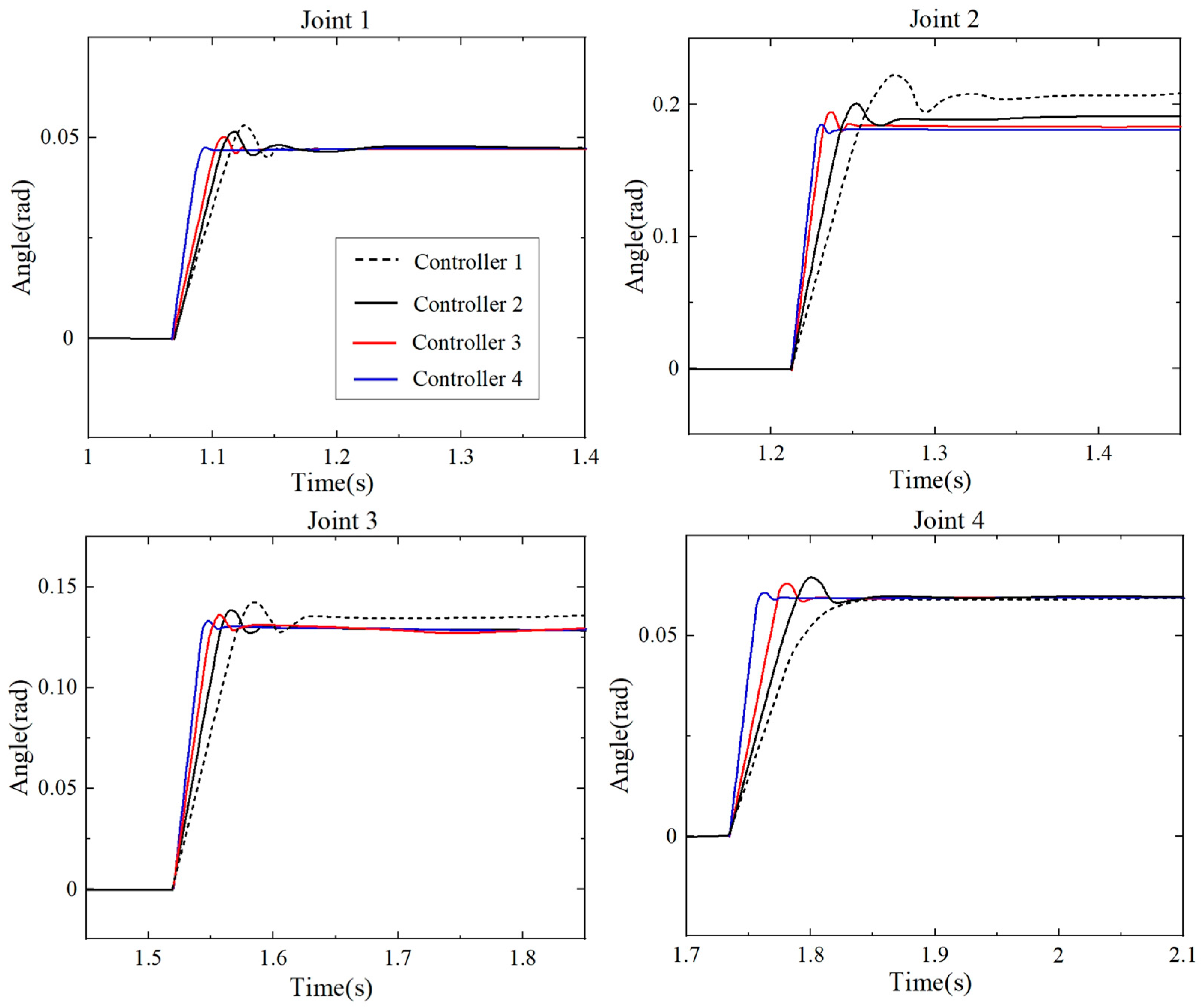
As described in Section 2, the robotic arm used in this study is a 5 DOF robotic arm, and each joint is equipped with a motor. Because the impact caused by the controller’s different types is negligible for joint 5, we provide a comparison of the step response performance of joints 1 to 4. As shown in Figure 9 and Figure 10, we cut out the step response curves from the stretching and retrieving process of the robotic arm, respectively. From Figure 9 and Figure 10, the step response trends of the four motors corresponding to the four controllers are not the same in the environment with disturbance. For example, some exhibit that Controller 1 achieves no overshoots, while others acquire. However, without the participation of DDPG, the parameters of PID are difficult to be tuned in Controller 1. Thereby, the delayed response time and large overshoots are acquired. The considerable deviation of steady-state values from the optimal steady-state values is also realized. Since the parameters of PID are tuned via DDPG, the response time of Controller 2 is advanced, and the steady-state values are closer to the optimal steady-state values. However, the online network cannot obtain the relation between environmental transformation and robotic arm motions, and it leads to low policy-making accuracy of DDPG. Therefore, the overshoots of Controller 2 cannot be significantly reduced. Because the improved DDPG utilizes FNN to update the environmental state of the online network, Controller 3 reaches early response time, and overshoots are reduced, but the effect is not remarkable. With the new DDPG in Controller 4 integrated with optimized FNN, the relation of the environmental transformation and robotic arm motions can be fully acquired, so the response time is earlier than that of others, and the overshoots are significantly reduced. Its steady-state values are close to the optimal steady-state values. The experimental results illustrate that the proposed Fuzzy-DDPG-PID controller can accelerate response speed and significantly reduce overshoots. It can make steady-state values close to the optimal steady-state values. It has better tracking control effects.
To verify the entire tracking process performance of the proposed Fuzzy-DDPG-PID controller, we also compare the tracking time, planning-tracking time difference (time-delay), maximum tracking error, and minimum tracking error of four controllers in Table 4. The planning algorithm and controllers utilized are the same as above. From Table 4, since the parameters of PID are difficult to tune without the participation of DDPG, the large values of four indexes are achieved by Controller 1, and the difference between the maximum and minimum tracking errors is large. Because the parameters of PID are tuned via DDPG, the values of four indexes are reduced by Controller 2 to 4. Due to the improvements of the update function and loss function in DDPG, the values of four indexes accomplished by Controller 4 are smaller, and the difference between maximum and minimum tracking error is also smaller. Therefore, the proposed Fuzzy-DDPG-PID controller can reach high tracking speed, small tracking error, and strong robustness.
To avoid the occasionality of the entire tracking process result, we repeat the experiment of the entire tracking process five times. In the repetitive experiments, the layouts and disturbances of the environment are changed. The five times experimental results of the entire tracking process are shown in Figure 11.

5. Conclusions

A novel planning and tracking approach for a mobile robotic arm to grab objects in an obstacle environment is proposed in this study. To verify the effectiveness of the proposed approach, the real-world object-grabbing experiments of a mobile robotic arm are conducted in obstacle environments, and the proposed approach is compared and analyzed. We compared the planning results of two different RRT* and proved that the improved RRT* planned shorter paths with smaller total turning angles. Based on the improved RRT*, we compared the planning results of two different APF-RRT*. The results illustrate that the improved APF-RRT* acquires fewer invalid branches and planning time. It has better planning performance compared to other algorithms. To avoid the occasionality of the one experiment result, we repeated the experiment three times. The results demonstrate that the improved APF-RRT* is superior to existing algorithms. Based on the improved APF-RRT*, we compare and analyze the tracking performance of the proposed Fuzzy-DDPG-PID controller. The step response performances of the joint motors illustrate that the proposed Fuzzy-DDPG-PID controller reaches an earlier response time and smaller overshoot. The steady-state values are close to the optimal steady-state values. Therefore, it has high response speed and control accuracy. The results of all the tracking processes of the four controllers demonstrate that the proposed Fuzzy-DDPG-PID controller can realize short tracking time and time delay. Its maximum and minimum tracking errors are small, and the difference values between the maximum and minimum tracking errors are also small. Therefore, the proposed Fuzzy-DDPG-PID controller can achieve high tracking speed, small tracking errors, and strong robustness. To avoid the occasionality of the one experiment result, we repeat the experiment of the entire tracking process five times. The results demonstrate that the proposed Fuzzy-DDPG-PID controller outperforms the existing controllers.
In future research, we will build more complex experimental environments, and more disturbances will be considered. We will also extend the research of mobile robotic arms from single-target object grabbing to multi-target object grabbing, with a single mobile robotic arm to multi-mobile robotic arms collaboration. Moreover, the planning and tracking research of the robotic arm will be extended to the target object grabbing performed via the unmanned surface vessel (USV) [35] and other unmanned platforms.

Author Contributions

Conceptualization, J.Y., J.W. and J.X.; methodology, X.W. and Z.Z.; formal analysis, J.Y. and Z.Z.; validation, J.W. and J.Y.; writing—original draft, J.Y., J.W. and J.X.; writing—review and editing, J.W., B.W. and X.C.; funding acquisition, Z.Z. All authors have read and agreed to the published version of the manuscript.

Funding

This work was supported in part by the National Natural Science Foundation of China (No. 61903008), Project of Cultivation for Young Top-notch Talents of Beijing Municipal Institutions (No. BPHR202203043).

Data Availability Statement

Data are contained within the article.

Conflicts of Interest

The authors declare no conflicts of interest.

References

  1. Li, Y.; Yang, C.G.; Yan, W.S.; Cui, R.X.; Annamalai, A. Admittance-Based Adaptive Cooperative Control for Multiple Manipulators with Output Constraints. IEEE Trans. Neural Netw. Learn. Syst. 2019, 30, 3621–3632. [Google Scholar] [CrossRef] [PubMed]
  2. Sepehri, A.; Moghaddam, A.M. A Motion Planning Algorithm for Redundant Manipulators using Rapidly Exploring Randomized Trees and Artificial Potential Fields. IEEE Access 2021, 9, 26059–26070. [Google Scholar] [CrossRef]
  3. Lu, X.H.; Jia, Y.M. Trajectory Planning of Free-Floating Space Manipulators with Spacecraft Attitude Stabilization and Manipulability Optimization. IEEE Trans. Syst. Man Cybern. Syst. 2021, 51, 7346–7362. [Google Scholar] [CrossRef]
  4. Wang, L.J.; Lai, X.Z.; Zhang, P.; Wu, M. A Control Strategy Based on Trajectory Planning and Optimization for Two-Link Underactuated Manipulators in Vertical Plane. IEEE Trans. Syst. Man Cybern. Syst. 2022, 52, 3466–3475. [Google Scholar] [CrossRef]
  5. Nie, J.M.; Wang, Y.A.; Mo, Y.; Miao, Z.Q.; Jiang, Y.M.; Zhong, H.; Lin, J. An HQP-Based Obstacle Avoidance Control Scheme for Redundant Mobile Manipulators under Multiple Constraints. IEEE Trans. Ind. Electron. 2023, 70, 6004–6016. [Google Scholar] [CrossRef]
  6. Dijkstra, E.W. A note on two problems in connexion with graphs. Numer. Math. 1959, 1, 269–271. [Google Scholar] [CrossRef]
  7. Hart, P.E.; Nilsson, N.J.; Raphael, B. A formal basis for the heuristic determination of minimum cost paths. IEEE Trans. Syst. Sci. Cybern. 1968, 4, 100–107. [Google Scholar] [CrossRef]
  8. Khatib, O. Real-time obstacle avoidance for manipulators and mobile robots. In Proceedings of the 1985 IEEE International Conference on Robotics and Automation, St. Louis, MO, USA, 25–28 March 1985; Volume 2, pp. 500–505. [Google Scholar]
  9. Lavalle, S.M. Rapidly-Exploring Random Trees: A New Tool for Path Planning. Res. Rep. 1999, 31, 293–308. [Google Scholar]
  10. Valle, S.M.L.; Kuffner, J.J. Randomized kinodynamic planning. Int. J. Robot. Res. 2001, 20, 378–400. [Google Scholar]
  11. Devaurs, D.; Siméon, T.; Cortés, J. Optimal Path Planning in Complex Cost Spaces with Sampling-Based Algorithms. IEEE Trans. Autom. Sci. Eng. 2016, 13, 415–424. [Google Scholar] [CrossRef]
  12. Ju, T.; Liu, S.; Yang, J.; Sun, D. Rapidly exploring random tree algorithm-based path planning for robot-aided optical manipulation of biological cells. IEEE Trans. Autom. Sci. Eng. 2014, 11, 649–657. [Google Scholar] [CrossRef]
  13. Iram, N.; Amna, K.; Zulfiqar, H. A Comparison of RRT, RRT* and RRT*-Smart Path Planning Algorithms. Int. J. Comput. Sci. Netw. Secur. 2016, 16, 20–27. [Google Scholar]
  14. Gammell, J.D.; Srinivasa, S.S.; Barfoot, T.D. Informed RRT: Optimal sampling-based path planning focused via direct sampling of an admissible ellipsoidal heuristic. In Proceedings of the 2014 IEEE/RSJ International Conference on Intelligent Robots and Systems, Chicago, IL, USA, 14–18 September 2014; pp. 2997–3004. [Google Scholar]
  15. Chi, W.Z.; Meng, M.Q.H. Risk-RRT: A robot motion planning algorithm for the human robot coexisting environment. In Proceedings of the 18th International Conference on Advanced Robotics (ICAR), Hong Kong, China, 10–12 July 2017; pp. 583–588. [Google Scholar]
  16. Yuan, Q.N.; Yi, J.H.; Sun, R.T.; Bai, H. Path Planning of a Mechanical Arm Based on an Improved Artificial Potential Field and a Rapid Expansion Random Tree Hybrid Algorithm. Algorithms 2021, 14, 321. [Google Scholar] [CrossRef]
  17. Jiang, Q.S.; Cai, K.; Xu, F.Y. Obstacle-avoidance path planning based on the improved artificial potential field for a 5 degrees of freedom bending robot. Mech. Sci. 2023, 14, 87–97. [Google Scholar] [CrossRef]
  18. Jin, Y. Decentralized adaptive fuzzy control of robot manipulators. IEEE Trans. Syst. Man Cybern. 1998, 28, 47–57. [Google Scholar]
  19. Mummadi, V. Design of robust digital PID controller for H-bridge soft switching boost converter. IEEE Trans. Ind. Electron. 2011, 58, 2883–2897. [Google Scholar] [CrossRef]
  20. Wai, R.J.; Lee, J.D.; Chuang, K.L. Real-time PID control strategy for maglev transportation system via particle swarm optimization. IEEE Trans. Ind. Electron. 2011, 58, 629–646. [Google Scholar] [CrossRef]
  21. Kim, K.; Rao, P.; Burnworth, J. Self-Tuning of the PID Controller for a Digital Excitation Control System. IEEE Trans. Ind. Appl. 2010, 46, 1518–1524. [Google Scholar]
  22. Muszynski, R.; Deskur, J. Damping of torsional vibrations in high dynamic industrial drives. IEEE Trans. Ind. Electron. 2010, 57, 544–552. [Google Scholar] [CrossRef]
  23. Khan, M.A.S.K.; Rahman, M.A. Implementation of a wavelet based MRPID controller for benchmark thermal system. IEEE Trans. Ind. Electron. 2010, 57, 4160–4169. [Google Scholar] [CrossRef]
  24. Wang, J.; Wang, C.H.; Chen, C.L.P. The Bounded Capacity of Fuzzy Neural Networks (FNNs) via a New Fully Connected Neural Fuzzy Inference System (F-CONFIS) with Its Applications. IEEE Trans. Fuzzy Syst. 2014, 22, 1373–1386. [Google Scholar] [CrossRef]
  25. Cheng, M.B.; Su, W.C.; Tsai, C.C. Robust tracking control of a unicycle-type wheeled mobile manipulator using a hybrid sliding mode fuzzy neural network. Int. J. Syst. Sci. 2010, 43, 408–425. [Google Scholar] [CrossRef]
  26. Du, G.L.; Liang, Y.H.; Gao, B.Y.; Otaibi, S.A.; Li, D. A Cognitive Joint Angle Compensation System Based on Self-Feedback Fuzzy Neural Network with Incremental Learning. IEEE Trans. Ind. Inform. 2020, 17, 2928–2937. [Google Scholar] [CrossRef]
  27. Mai, T. Hybrid adaptive tracking control method for mobile manipulator robot based on Proportional–Integral–Derivative technique. Proc. Inst. Mech. Eng. Part C J. Mech. Eng. Sci. 2021, 235, 6463–6480. [Google Scholar] [CrossRef]
  28. Ander, I.; Elena, L.; Ander, A.; Andoni, R.; Iker, L.; Carlos, T. Learning positioning policies for mobile manipulation operations with deep reinforcement learning. Int. J. Mach. Learn. Cybern. 2023, 14, 3003–3023. [Google Scholar]
  29. Mnih, V.; Kavukcuoglu, K.; Silver, D.; Rusu, A.A.; Veness, J.; Bellemare, M.G.; Graves, A.; Riedmiller, M.; Fidjeland, A.K.; Ostrovski, G.; et al. Human-level control through deep reinforcement learning. Nature 2015, 518, 529–533. [Google Scholar] [CrossRef]
  30. Lillicrap, T.P.; Hunt, J.J.; Pritzel, A. Continuous control with deep reinforcement learning. arXiv 2015, arXiv:1509.02971. [Google Scholar]
  31. Wang, F.; Ren, B.M.; Liu, Y.; Cui, B. Tracking Moving Target for 6 degree-of-freedom Robot Manipulator with Adaptive Visual Servoing based on Deep Reinforcement Learning PID Controller. Rev. Sci. Instrum. 2022, 93, 045108. [Google Scholar] [CrossRef]
  32. Geng, H.; Hu, Q.; Wang, Z. Optimization of Robotic Arm Grasping through Fractional-Order Deep Deterministic Policy Gradient Algorithm. J. Phys. Conf. Ser. 2023, 2637, 012006. [Google Scholar] [CrossRef]
  33. Afzali, S.R.; Shoaran, M.; Karimian, G. A Modified Convergence DDPG Algorithm for Robotic Manipulation. Neural Process. Lett. 2023, 55, 11637–11652. [Google Scholar] [CrossRef]
  34. Spong, M.W.; Hutchinson, S.; Vidyasagar, M. Robot Modeling and Control. Ind. Robot Int. J. 2006, 17, 709–737. [Google Scholar]
  35. Yu, J.B.; Yang, M.; Zhao, Z.Y.; Wang, X.Y.; Bai, Y.T.; Wu, J.G.; Xu, J.P. Path planning of unmanned surface vessel in an unknown 593 environment based on improved D*Lite algorithm. Ocean Eng. 2022, 266, 112873. [Google Scholar] [CrossRef]
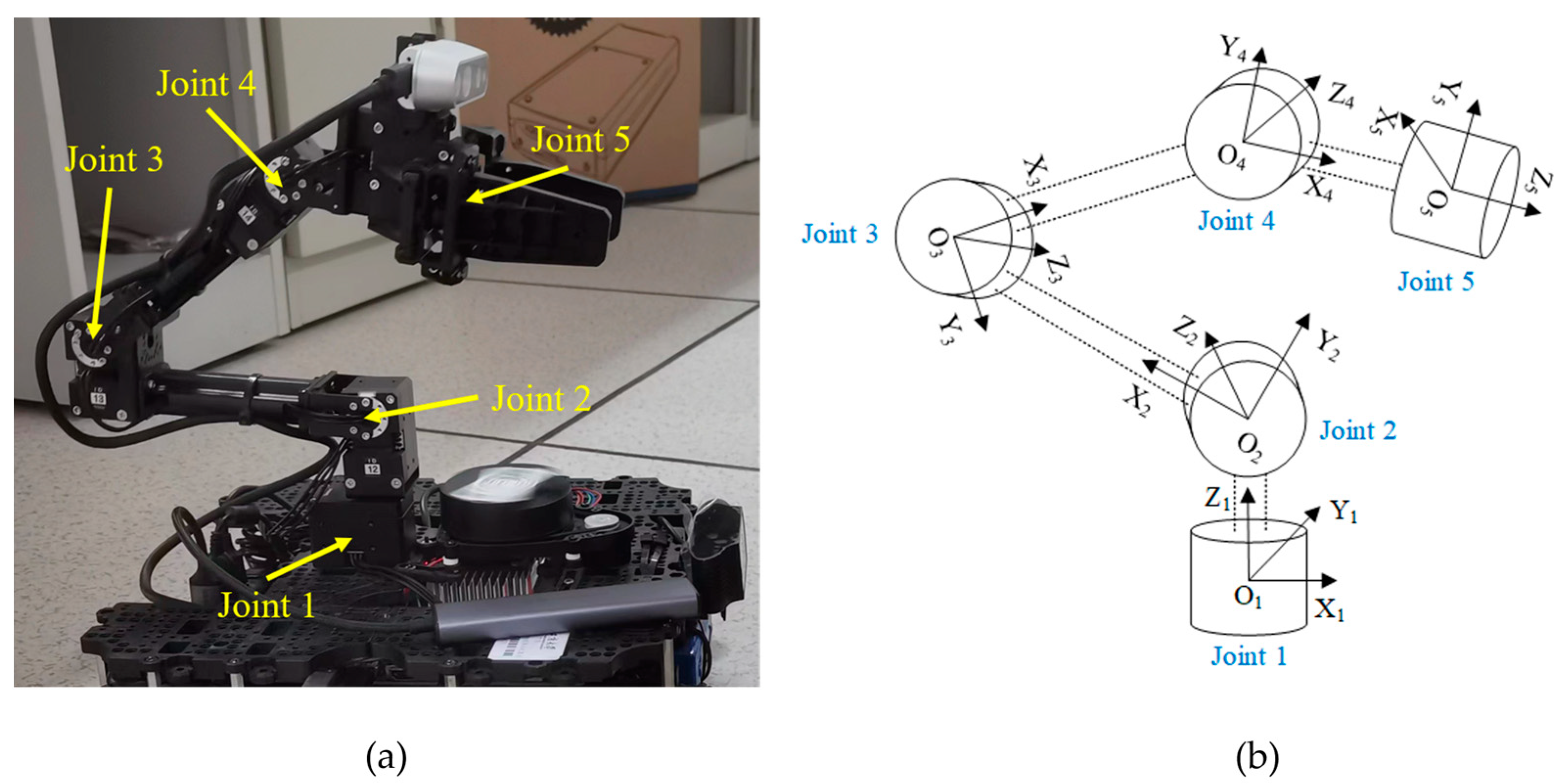
Figure 1. The robotic arm and its joint coordinate system (a) The robotic arm part of Turtlebot3-ARM and (b) The coordinate system of the robotic arm joint.
Machines 12 00019 g001
Figure 2. The principle of the improved RRT* (a) Current State of random tree, (b) Selection of q p a r e n t , (c) Dubins smooth process and (d) New state of random tree.
Machines 12 00019 g002
Figure 3. The principle of the improved APF-RRT* (a) The state without APF and (b) The state with APF.
Machines 12 00019 g003
Figure 4. The principle of the proposed Fuzzy-DDPG-PID controller.
Machines 12 00019 g004
Figure 5. The principle of the Fuzzy-DDPG.
Machines 12 00019 g005
Figure 6. The structure of FNN.
Machines 12 00019 g006
Figure 7. The entire grabbing task in real-world environment.
Machines 12 00019 g007
Figure 8. The real-time state of robotic arm in MoveIt.
Machines 12 00019 g008
Figure 9. The step response performance of stretching.
Machines 12 00019 g009
Figure 10. The step response performance of retrieving.
Machines 12 00019 g010
Figure 11. The five times experimental results of the entire tracking process.
Machines 12 00019 g011
Table 1. The parameters of Turtlebot3-ARM.
ParametersDefinitionNumerical Value
w (rad/s)Maximum angular velocity of motor0.5
a1 (rad)Maximum angle of Joint 1
a2 (rad)Maximum angle of Joint 2π
a3 (rad)Maximum angle of Joint 3π
a4 (rad)Maximum angle of Joint 4π
a5 (rad)Maximum angle of Joint 50.5π
x (m)Minimum x-axis length of obstacle0.05
y (m)Minimum y-axis length of obstacle0.05
z (m)Minimum z-axis length of obstacle0.05
Rs (m)Safety range of mobile robotic arm0.05
Table 2. The planning results for target object grabbing.
Algorithm NamePath Length (m)Total Steering Angle (°)Branch AccountPlanning Time (s)
Algorithm 10.431295.323412.64
Algorithm 20.326475.213011.75
Algorithm 30.277161.542310.44
Algorithm 40.235554.85159.31
Table 3. The three time planning results for target object grabbing.
CoordinatesAlgorithm NamePath Length (m)Total Steering Angle (°)Branch AccountPlanning Time (s)
(0.142, 0.137)
(−0.145, −0.134)
Algorithm 10.413490.433113.08
Algorithm 20.332974.552612.59
Algorithm 30.272662.132111.97
Algorithm 40.217350.771311.05
(−0.138, 0.143)
(0.155, −0.149)
Algorithm 10.452797.664014.62
Algorithm 20.359178.733513.29
Algorithm 30.286464.352712.47
Algorithm 40.248556.311610.84
(0.133, −0.156)
(−0.148, 0.143)
Algorithm 10.429794.653212.47
Algorithm 20.336276.312411.77
Algorithm 30.253860.871710.95
Algorithm 40.225351.94109.48
Table 4. The performance comparison of the entire tracking process.
ControllerTracking Time (s)Time-Delay (s)Maximum Tracking Error (m)Minimum Tracking Error (m)
Controller 112.091.250.04850.0309
Controller 211.460.970.04330.0277
Controller 39.730.640.03590.0251
Controller 47.330.490.02830.0195
Disclaimer/Publisher’s Note: The statements, opinions and data contained in all publications are solely those of the individual author(s) and contributor(s) and not of MDPI and/or the editor(s). MDPI and/or the editor(s) disclaim responsibility for any injury to people or property resulting from any ideas, methods, instructions or products referred to in the content.