Article

A Control Architecture for Developing Reactive Hybrid Remotely Operated Underwater Vehicles

by
Fernando Gómez-Bravo
1,2,*,
Alejandro Garrocho-Cruz
1,
Olga Marín-Cañas
1,
Inmaculada Pulido-Calvo
3,
Juan Carlos Gutierrez-Estrada
3 and
Antonio Peregrín-Rubio
4,5
1
Department of Electronic Engineering, Computer Systems and Automation, Technical School of Engineering, Campus El Carmen, University of Huelva, 21007 Huelva, Spain
2
Huelva Scientific and Technological Center (CCTH), University of Huelva, 21007 Huelva, Spain
3
Agroforestry Sciences Department, Technical School of Engineering, Campus El Carmen, University of Huelva, 21007 Huelva, Spain
4
Center for Advanced Studies in Physics, Mathematics and Computing (CEAFMC), University of Huelva, 21007 Huelva, Spain
5
Andalusian Research Institute in Data Science and Computational Intelligence (DaSCI), University of Huelva, 21007 Huelva, Spain
*
Author to whom correspondence should be addressed.
Machines 2024, 12(1), 1; https://doi.org/10.3390/machines12010001
Submission received: 2 November 2023 / Revised: 6 December 2023 / Accepted: 11 December 2023 / Published: 19 December 2023
(This article belongs to the Special Issue Mobile Robotics: Mathematics, Models and Methods)

Abstract

:
This article introduces a control architecture designed for the development of Hybrid Remotely Operated Underwater Vehicles. The term ”Hybrid” characterizes Remotely Operated systems capable of autonomously executing specific operations. The presented architecture maintains teleoperation capabilities while enabling two fully autonomous applications. The approach emphasizes the implementation of reactive navigation by exclusively utilizing data from a Mechanical Scanned Imaging Sonar for control decisions. This mandates the control system to solely react to data derived from the vehicle’s environment, without considering other positioning information or state estimation. The study involves transforming a small-scale commercial Remotely Operated Underwater Vehicle into a hybrid system without structural modifications, and details the development of an intermediate Operational Control Layer responsible for sensor data processing and task execution control. Two practical applications, inspired by tasks common in natural or open-water aquaculture farms, are explored: one for conducting transects, facilitating monitoring and maintenance operations, and another for navigating toward an object for inspection purposes. Experimental results validate the feasibility and effectiveness of the authors’ hypotheses. This approach expands the potential applications of underwater vehicles and facilitates the development of Hybrid Remotely Operated Underwater Vehicles, enabling the execution of autonomous reactive tasks.

1. Introduction

Over the last years, there has been a growing demand for the involvement of underwater vehicles in many different type of operations [1,2,3]. This demand has gained particular significance in applications related to natural resources monitoring, with a notable emphasis on the management and maintenance of aquaculture facilities [4,5]. Among the emerging technologies that show promise for deployment in these contexts, Autonomous Underwater Vehicles (AUV) and Remotely Operated Underwater Vehicles (ROV) stand out due to their capacity to collect information through non-destructive and minimally intrusive methods [6]. In this sense, the development of technological solutions to support the sustainable operation of aquaculture facilities and ensure their economic viability is significantly important [7]. This relevance aligns with the objectives outlined in the European Union’s “Blue Growth Plan” [8], which emphasizes the role of smart and sustainable aquaculture with inclusive production in the future, thus constituting a substantial food resource for the European population.
Recently, significant attention has been directed toward the modernization of aquaculture, particularly in the development of methodologies for biomass and population growth estimation [9,10], as well as the measurement of physical–chemical parameters that characterize the aquatic ecosystem [11]. Small-scale ROV systems have proven to be valuable tools for these applications due to their versatility and ability to maneuver effectively within confined spaces. The initial designs of ROVs dedicated to data acquisition and control in aquaculture facilities were pioneered by SINTEF [12] and SIMRAD Subsea [13] in 1985 [14]. Since then, the design and construction of ROVs have continued to evolve with direct applications in aquaculture [15,16,17].
These vehicles offer multiple applications in maintenance and operational tasks within aquaculture farms. Notably, they are valuable for locating different types of elements of interest, such as fish, schools (large concentrations of fish), or other objects with diverse characteristics. The presence of foreign elements in the farm pond can significantly impact its exploitation, making their identification and monitoring essential for effective management [18].
In natural or open-water environments, high water turbidity is a common challenge that makes underwater visibility difficult, rendering the cameras traditionally carried by ROVs ineffective in providing useful information. In such conditions, the detection of elements of interest relies on the use of proximity sensors, such as sonars, which offer environmental information to the operator. Nevertheless, the same turbidity raises safety concerns for vehicle navigation. The reduced visibility makes it challenging for the operator to maintain a clear reference to the ROV’s location and the detected elements of interest. It is within this context that the concept of Hybrid Remotely Operated Underwater Vehicle (HROV) is introduced, denoting an underwater vehicle capable of being manually operated while also presenting the capacity to autonomously execute specific operations based on user requirements [19,20].
In the literature, various HROV developments have been documented, each featuring different levels of autonomy designed to suit specific applications. Notable projects in this domain include “Double Eagle Sarov” [21]; “Nereus” [22]; “Aquanaut” [23]; “Ocean One” [24]; HROV-Arch [25]; and “MERBOTS” [26], as presented in [20].
To implement HROV systems, addressing a series of challenges is necessary, spanning aspects like mechanical design, control architecture, and the Human–Machine Interface (HMI) [20]. Small ROVs designed for aquaculture maintenance tasks appear to be a highly advantageous choice for HROV development. This choice is based on understanding that the operations for which the former are designed might demand a combination of operator-driven and autonomous tasks due to water turbidity. Furthermore, the mechanical design of these small ROVs does not require significant adaptations, as autonomous interventions can be confined to short distances, facilitating the maintenance of the tether throughout the operations.
Particularly, this work primarily aims to detail the control architecture designed for transforming a small-scale commercial ROV into an HROV. Moreover, the authors specifically operate under the assumption that it is feasible to integrate traditional reactive navigation capabilities, commonly employed in mobile robotics, into HROVs. They believe these capabilities can prove valuable in the execution of typical tasks, such as those performed in the maintenance and management of open-water aquaculture facilities. The developed architecture is specially designed to support this type of navigation and its corresponding applications.
An outstanding characteristic that differentiates the approach presented in this article compared to the developments reported in the scientific literature is its emphasis on implementation within pre-existing ROVs, without requiring any structural modifications to the system. In contrast, most of the previous HROVs reported were originally designed as hybrid systems from the beginning. Furthermore, this proposal is particularly oriented towards reactive navigation applications, whereas previous developments have typically focused on executing operations based on navigating pre-established routes or performing manipulation tasks.
This research was conducted as part of the KTTSeaDrones Project [27], which received funding from the European Union under the Interreg V-A Spain-Portugal Program (POCTEP). The project was led by the University of Huelva.
The article follows the following structure: after the introduction, Section 2 describes the materials and methods used in the project, details the theoretical basis of the proposed architecture, outlines the modules comprising it, and analyzes their interaction with the hardware components. Section 3 presents the experiments conducted to validate the authors’ hypothesis. Finally, Section 4 is devoted to discussing the scope of the proposed solution, the future developments, and the conclusions.

2. Materials and Methods

2.1. Transforming an ROV in a Reactive Hybrid ROV

This section describes the main characteristics of the commercial ROV transformed into an HROV through the implementation of the proposed architecture. The basis of the development of this architecture is also presented.

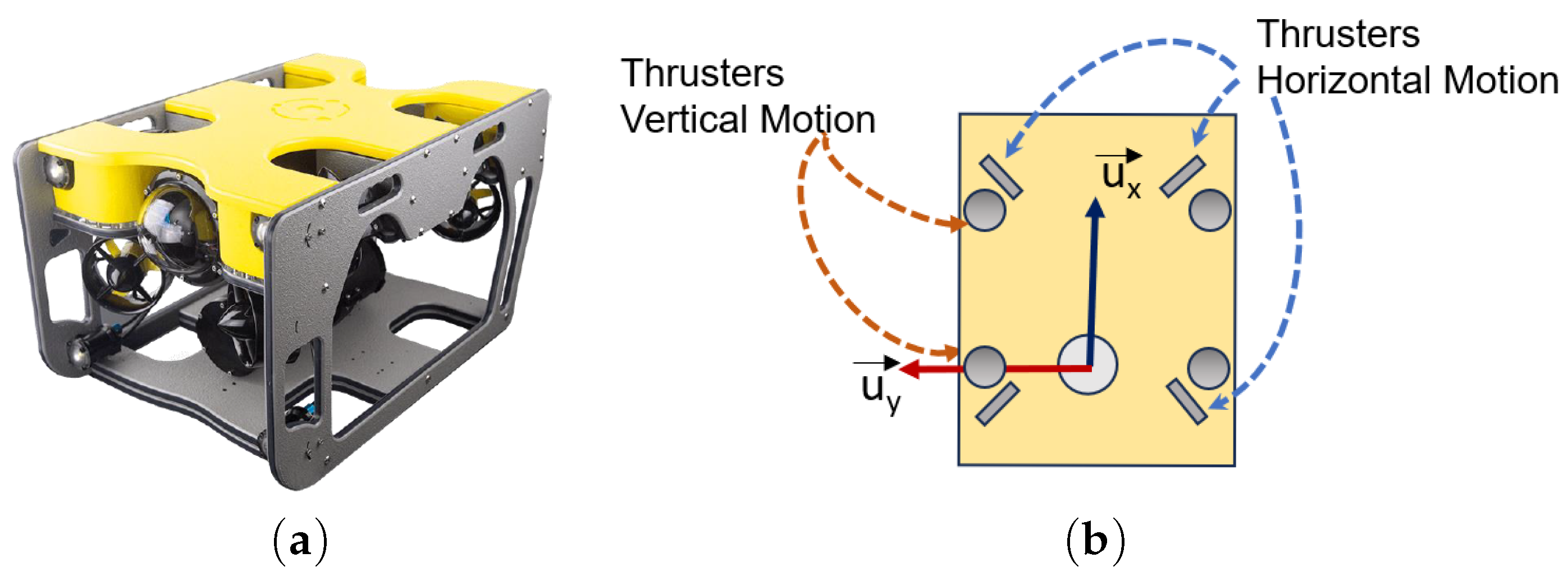
2.1.1. Sibiu PRO: A Small-Scale Commercial ROV

Small-Scale commercial ROV Sibiu PRO (see Figure 1a) incorporates eight thrusters: four to control movements in the vertical direction, and another four, symmetrically oriented, to control movements in the horizontal plane (Figure 1b). This arrangement helps maintain stability and balance when controlling the ROV movements.
It uses rechargeable lithium batteries (LiFePO4) as a source of energy for under water operation. Its technical specifications are shown in Table 1:
The Sibiu Pro control system consists of a Raspberry Pi and a low-level controller or autopilot known as Pixhawk (version 2.4.8) [28]. Additionally, its operation requires the use of a computer to execute a program serving as a Human–Machine Interface (a version of the QGroundControl program [29] is distributed with the Sibiu Pro), acting as a Ground Control Station (GCS). This structure is illustrated in Figure 2. The primary function of the Raspberry Pi is to act as a bridge for message transmission between the PixHawk and the GCS, supported by the MAVLink communication protocol [30]. The PixHawk is responsible for executing ArduSub V4.0 [31], an open-source software designed specifically for AUVs and ROVs derived from ArduPilot [32]. This module has the capability of interpreting the control commands issued by the operator via a manual device connected to the GCS. It adjusts the thrust of the propellers to navigate the vehicle in the direction specified by the operator.
Sibiu PRO incorporates a set of different sensors integrated into its platform. Among these sensors, the Inertial Measurement Unit (IMU) is particularly relevant for this study. The IMU is constructed using Micro Electromechanical Sensors (MEMS), making it compact and cost effective. It can relay data to the PixHawk via the I2C or SPI serial communication [33].
Furthermore, two additional sensors are integrated into the system. The first is a Ping Echosounder Sonar from BlueRobotics [34] (see Figure 3a), designed to measure the distance to the bottom. Its functionality is based on a piezoelectric transducer, which emits an acoustic pulse into the water and subsequently receives the returning echo. The Pixhawk controller offers the capability to control the vehicle’s depth based on readings from this sensor.
The second supplementary sensor is the Ping360 Sonar from BlueRobotics [35] (Figure 3b). It operates as a Mechanical Scanned Imaging Sonar (MSIS) system, conducting a 360 scan using an acoustic beam with a broad vertical aperture and a narrow horizontal opening, generating acoustic cross-sections of the surrounding environment [18]. The Ping360 Sonar consists of a transducer mounted on a motor that rotates in 0.9-degree increments, creating a circular image of the surroundings with a maximum range of 50 m. It is highly reflective towards solid materials with significantly different densities compared to water, resulting in strong echoes. Conversely, materials such as mud, silt, sand, and aquatic vegetation produce weaker echoes as they possess a density similar to that of water or tend to absorb acoustic energy [35]. The sensor takes approximately 8.78 s to complete a scan. Figure 3c shows the integration of Ping360 on the Sibiu Pro.

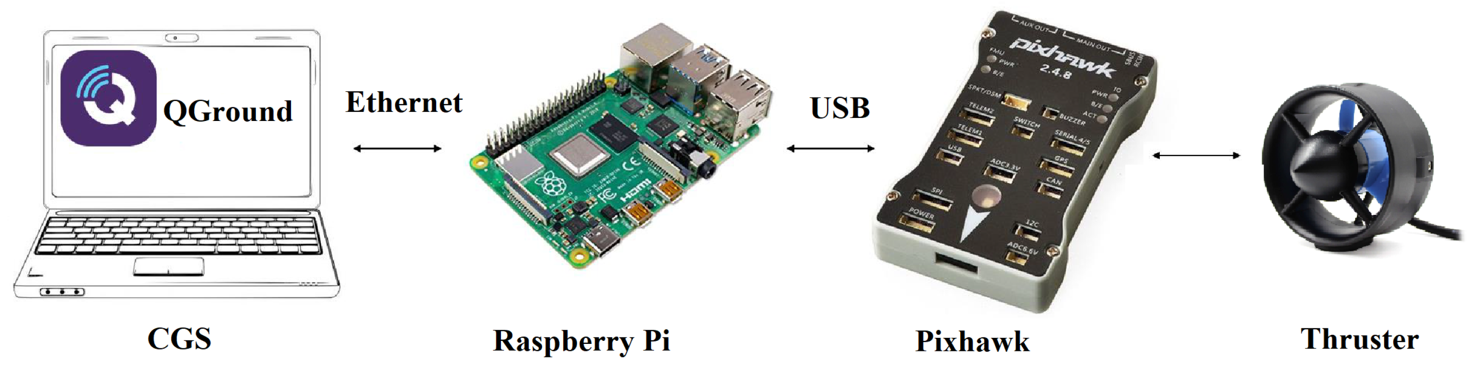
2.1.2. From a ROV to a HROV

Traditional control architectures associated with autonomous watercraft are typically based on Guidance, Navigation, and Control (GNC) concepts [1], as shown in Figure 4. In this framework, the Navigation module is responsible for providing pose references to the Control module. From the user’s perspective, these vehicles exhibit autonomous behavior, meaning that once the user defines a desired mission (traditionally a route to follow), the system operates independently. AUVs typically follow this architecture.
In contrast, the control architecture of ROVs, as depicted in Figure 5, replaces the Guidance module with a user interface device, enabling the vehicle to be manually guided by an operator. In this scenario, the control loop is primarily operator-driven with visual feedback. This feedback may occur directly through the operator’s ability to visually monitor the underwater vehicle’s movements or via onboard cameras that provide a view from the watercraft’s perspective. Additionally, there could exist a Navigation module that processes data and provides feedback to the Control module for automated tasks, such as depth and orientation maintenance. Despite the lack of autonomy, remote manual operation can be advantageous in terms of the flexibility it provides to the operator, allowing easy definition of the system’s movements when performing specific maintenance or data collection tasks. However, many situations arise where visual feedback is not feasible, primarily due to water turbidity, especially when the activity involves navigation in outdoor facilities. In such circumstances, the watercraft’s operation could benefit from the system’s ability to execute certain autonomous behaviors. This requirement gives rise to the concept of HROV [20], i.e., a vehicle designed to enable direct operator control while also providing autonomous capabilities for specific operations triggered by user requests.
A common characteristic observed in HROVs control systems, as documented in the scientific literature, is their dependency on the specific intended application. Notably, several noteworthy developments exemplify this trend. Nereus [36] is an HROV designed for routine ocean research, facilitating exploration in remote and challenging areas, even beneath the Arctic ice cap. Double Eagle Sarov [37] is a watercraft that serves as both an AUV, capable of detection, classification, and identification, and as a ROV for mine disposal. Ocean One [38] operates as a bimanual underwater humanoid robot, offering haptic feedback for precise exploration of ocean depths, specifically aimed at the recovery of submerged archaeological artifacts. Aquanaut [39] primarily services sub-sea oil and gas installations, showcasing the ability to transform into an underwater humanoid capable of executing manipulation maneuvers. OPTIHROV [40] is a proof-of-concept project demonstrating telerobotic capabilities using an untethered, optically connected HROV. It aims to develop an underwater intervention system placed at a considerable distance from the operator, enabling a high degree of autonomy.
The architecture of each prototype prioritizes the development of autonomy adapted to its specific applications through the implementation of control algorithm intended to facilitate planed navigation, search, or manipulation tasks.
Considering approaches focused on the development of control architectures for HROVs [20], it is worth mentioning projects HROV-Arch [41] and MERBOTS [42]. HROV-Arch targets a hybrid ROV system tailored for oceanographic research, particularly emphasizing operations under ice. Its control architecture predominantly enables human control, switching to full autonomy during accidental loss of contact or when the vehicle needs to return to the mother vessel. MERBOTS concentrates on underwater search and recovery interventions, employing a multifunctional HROV system with a manipulator and a hoover for supervised intervention tasks. Both projects aim to augment human interaction by supporting user operations on demand and facilitating smooth transitions between autonomous and teleoperated modes. The control architecture developed in MERBOTS notably emphasizes the support of manipulation interventions during recovery maneuvers. This is achieved through the creation of a specific Human–Machine Interface, which enables the seamless combination of the operator’s actions and the intervention of the automatic control system, as illustrated in [20].
In this sense, the presented approach maintains teleoperation capabilities while introducing two applications where the system autonomously performs tasks, enabling user intervention in operation settings. One application aims to assist in monitoring and maintenance tasks in outdoor aquaculture facilities by controlling the tracking of transects. The other application pertains to inspection operations, allowing the system to identify and maneuver the vehicle closer to objects selected by the operator. Unlike the previously mentioned projects, these applications are designed to run within closed areas, and autonomous behavior is based on developing purely reactive tasks based on measurement taken from the environment. Here, the operator sets higher-level operation objectives, delegating task execution to the system controller. Thus, hybrid functionality allows the user to intervene in the operation either at a high level or at any point during autonomous execution, assuming complete control of the mission.
To achieve this objective, a specific aim of this project involves enhancing the control architecture of a commercial ROV by introducing a new layer, the Operational Control Layer (OCL), which adds a certain level of autonomy, as shown in Figure 6. This new layer takes into account both sensor data and user preferences and is responsible for executing basic tasks by sending fundamental commands to the low-level controller rather than providing references as realized by the Guidance module. The switching module, depicted in Figure 6, enables control commands directed to the low-level controller to originate from either the user interface or the OCL.
Moreover, the approach outlined in this article is particularly ambitious, since implementing a pure reactive behavior implies that the control system should only react to data from sensors detecting the vehicle’s environment, without taking into account other positioning information or state estimation [43]. This proposal is justified by the current limitations in inertial navigation and underwater vehicle positioning systems, which are often either imprecise or prohibitively expensive. Additionally, disturbances can affect IMU devices, particularly when metallic infrastructure interferes with the correct functioning of magnetometers.
This approach, commonly employed in Unmanned Ground Vehicles (UGVs) for performing precise local maneuvers, presents a substantial scientific challenge in underwater vehicles. Unlike the sonar or Lidar sensors utilized in ground robotics, the sensor used to perceive the HROV’s environment (Ping360 sonar) is characterized by a significant delay in obtaining measurements. This delay represents a chalenge when implementing such strategies. However, it is important to note that this limitation did not prevent the validation of the approach proposed in this article. As is shown later, experimental tests were conducted to confirm the authors’ initial hypothesis.

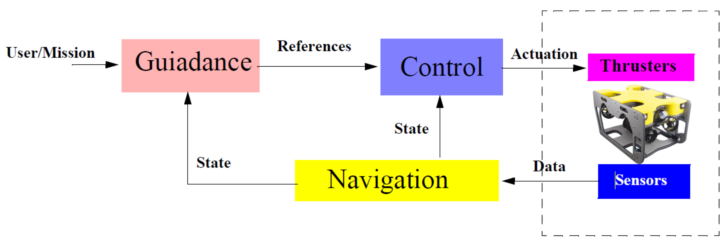
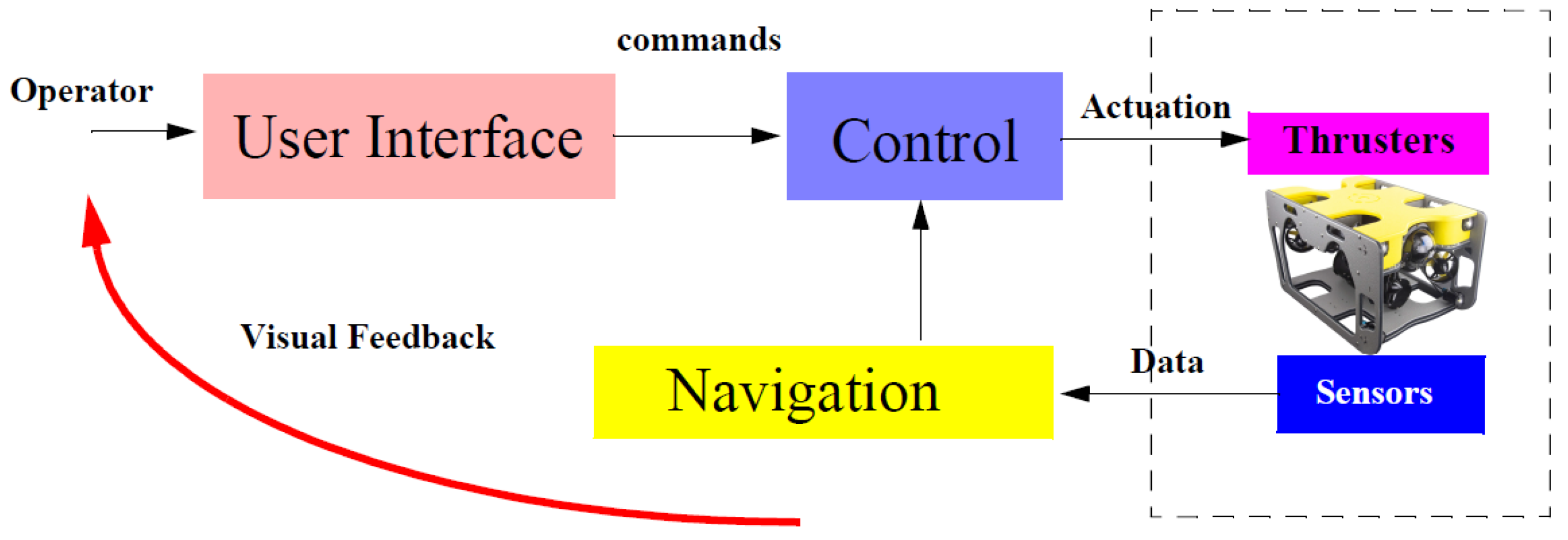
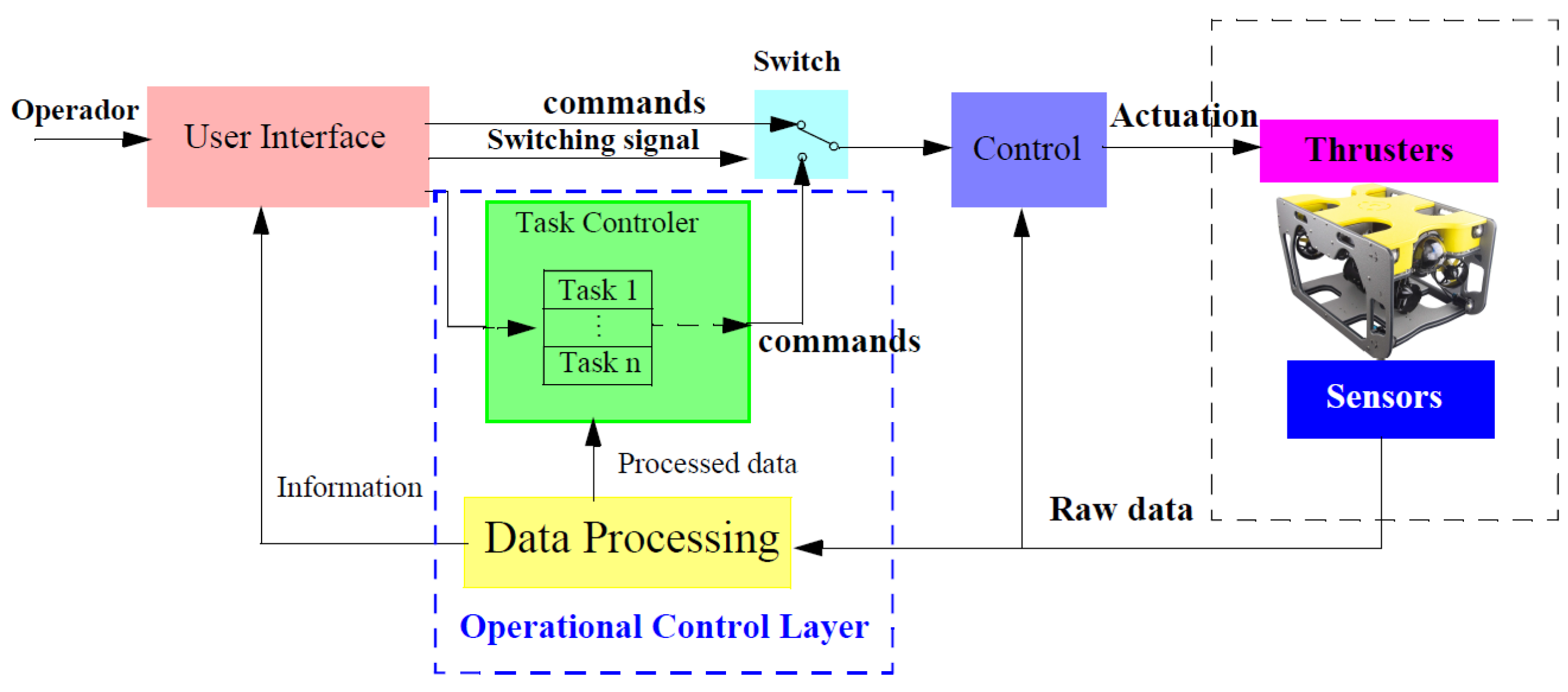
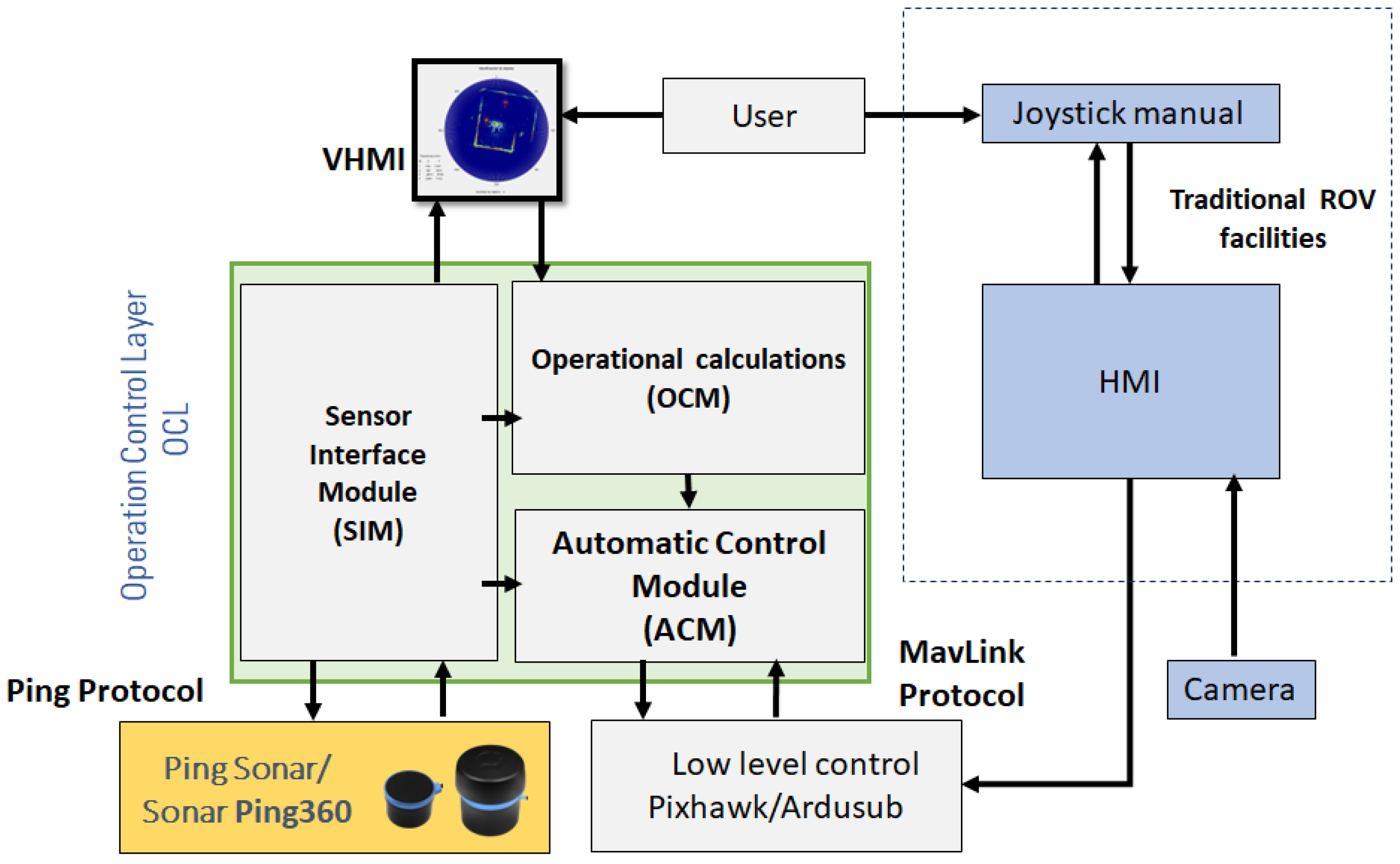
2.2. HROV Control Architecture: The Operational Control Layer

The architecture shown in Figure 7 essentially reflects the initial hypothesis articulated above. The depicted system offers two primary modes of operation. Firstly, it can be manually piloted through the conventional controls of a traditional ROV, relying on visual data from a camera or different sensors. This manual control involves a joystick or a similar interface for managing vehicle motion.
On the other hand, the same diagram depicts the intermediate Operational Control Layer, enabling the ROV to transform into a hybrid vehicle capable of supporting both modes of operation: autonomous and teleoperated.
This intermediate layer includes different modules. Notably, the Visual Human Machine Interface (VHMI) module and the Operational Calculations Module (OCM) are two key elements. In this approach, the VHMI module provides the user with information and enables the selection of a specific operation, as well as the input of parameters relevant to the chosen task. The OCM module is responsible for receiving data regarding the operation in use and conducting preliminary calculations before starting the specific task.
Furthermore, this architecture also includes the Sensor Interface Module (SIM) and the Automatic Control Module (ACM) that are discussed later. This elements are tasked with interfacing with the low-level components of the system and implementing an effective control strategy to provide autonomy to the vehicle. SIM and ACM operate on the GCS (the external computer) and are custom designed within the Matlab environment.
In accordance with the specifications of Ardusub, which is the low-level control software running on the Pixhawk, the ACM module transmits the results of the corresponding control algorithm to the low-level controller. A connectivity diagram illustrating the link between the ACM module and the Pixhawk is presented in Figure 8. This communication is established in compliance with the MAVLink protocol, supported by the UDP transport protocol over Ethernet along the tether of the watercraft.
Simultaneously, the SIM module interfaces with the PING360 Sonar using the Ping protocol [44], also employing UDP via the same physical channel. This protocol enables the system to initiate a reading request and receive a raw data frame each time the sonar executes a scan. The SIM module processes these data to extract information that is subsequently utilized by the ACM module to execute the selected mission. The specific data processing techniques in the SIM module and their utilization during vehicle control are detailed in subsequent sections.

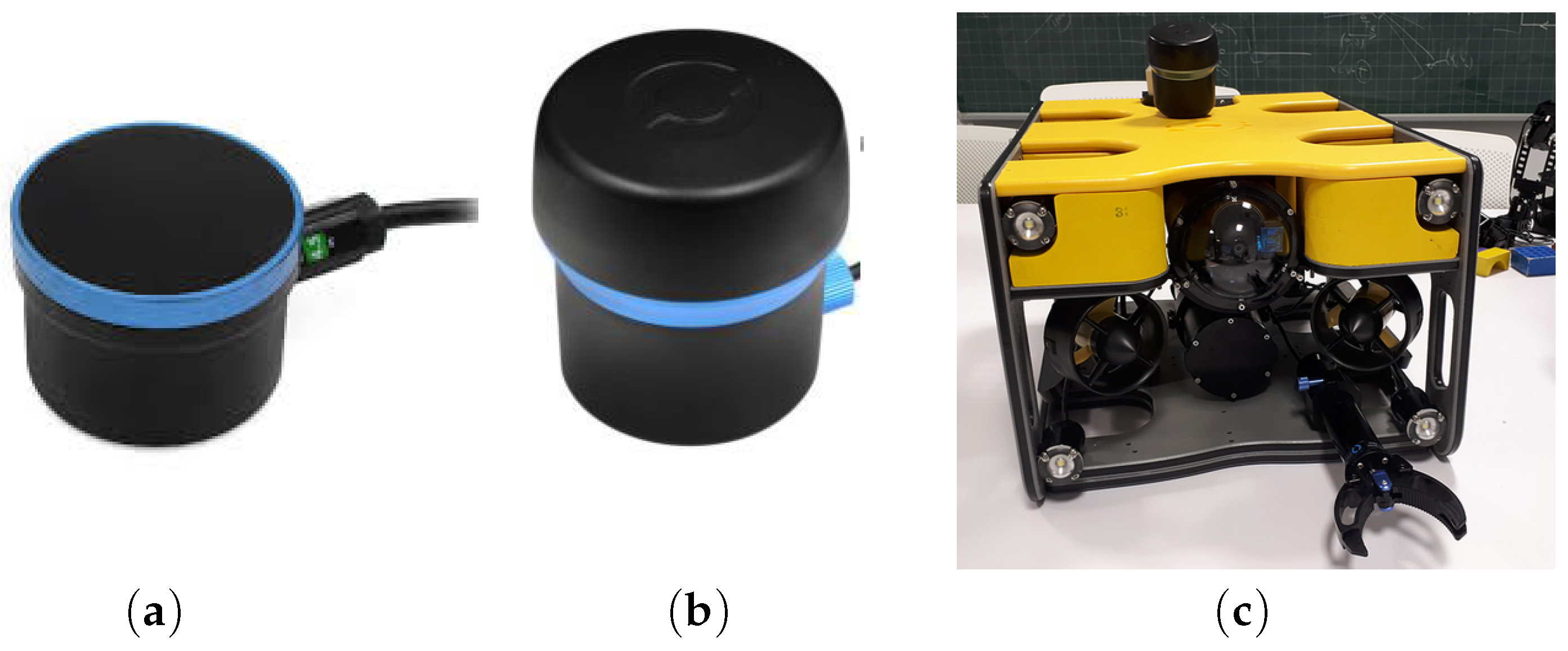
2.3. Sensor Interface Module

Within the SIM, the raw data can undergo processing to achieve two different objectives, depending on the specific application. The first objective is to provide the user with information regarding the objects in the vicinity of the HROV, enabling the operator to potentially select one of these objects for the vehicle to approach. The second objective is to calculate the distance and angle between the vehicle and the pool wall it is facing. Both of these objectives are relevant in the context of vehicle control and autonomous operation, as is shown later. In the following sections, these two data processing mechanisms are described in detail.

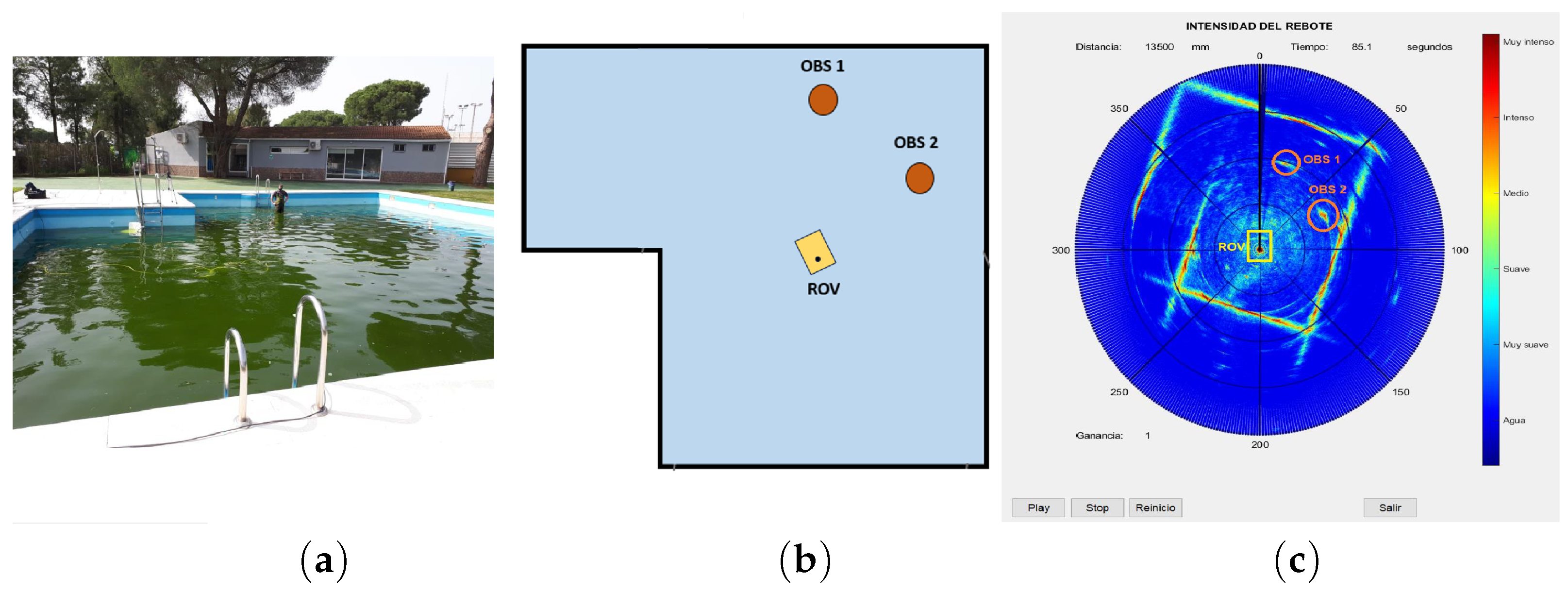
2.3.1. Object Detection

The data collected by the Ping360 sonar supply information about the HROV’s environment. For each angle, a set of 1200 values is obtained, representing the echo strength received from various distances. These values are quantified by integers within the range of 0 to 255, with 0 meaning no bounce and 255 representing maximum intensity. These values are displayed in the interface through a color palette, where each color represents the strength of the echo bounce. Figure 9c illustrates a typical image generated by the developed VHMI. A methodology is applied to this data structure, allowing for the identification of objects that may be of interest to the operator [18]. To achieve this objective, a clustering-based processing technique [45] is employed to group these elements based on their proximity, connectivity, and the uniformity of the received signal’s intensity. Consequently, the elements within the data structure are categorized and targeted according to the strength of the returned echo, and then grouped by their proximity and connectivity, resulting in a set of clusters. The obtained information represents physical elements that produce an echo signal of similar intensity and exhibit a compact spatial distribution. As a result, a matrix of potential objects is generated, with each object characterized by the coordinates of its cluster’s centroid in the vehicle’s local frame, its dimensions, and the echo signal intensity. Figure 9 illustrates how two objects within a pool are identified and distinguished using a particular label for each one.

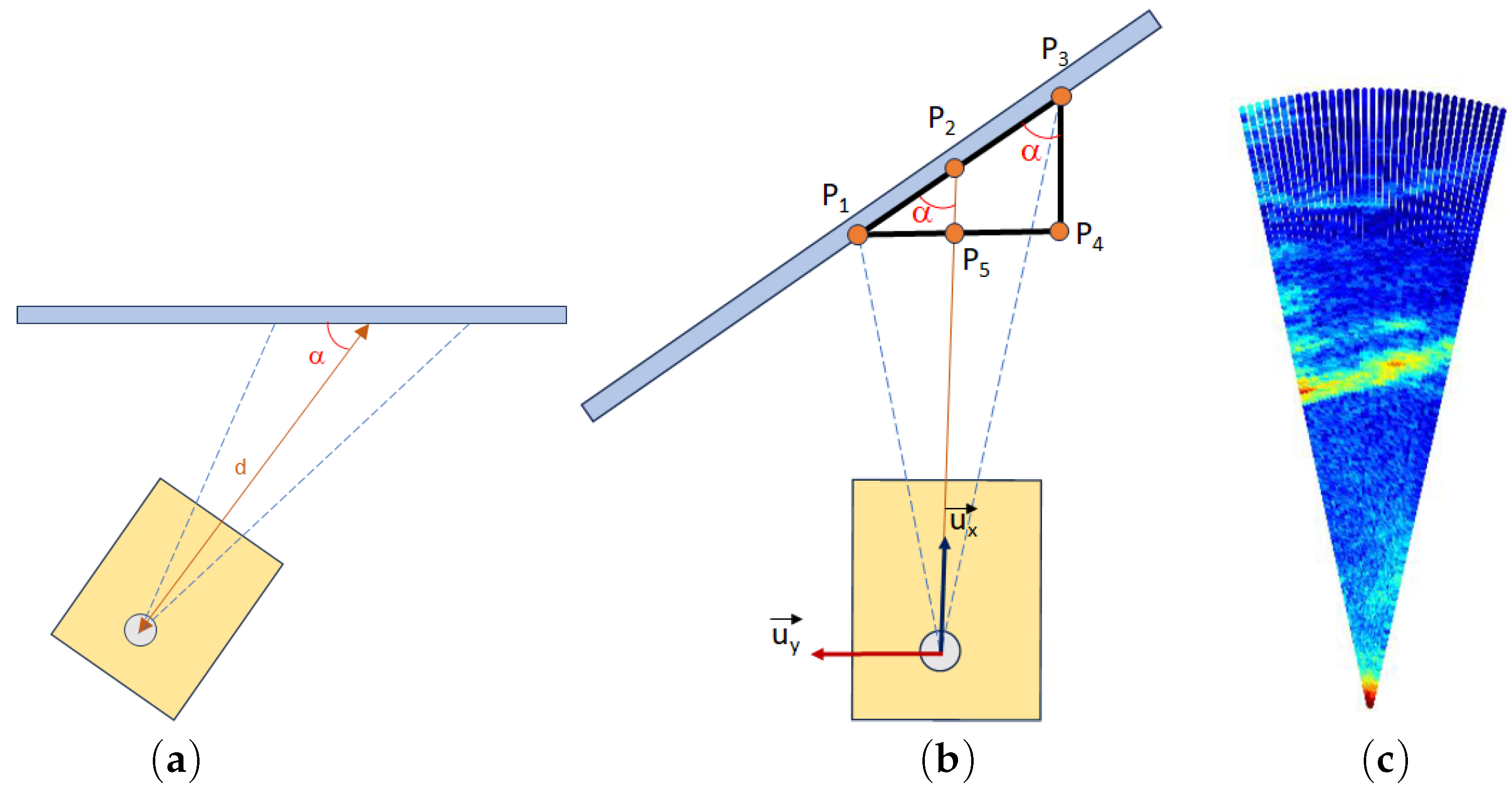
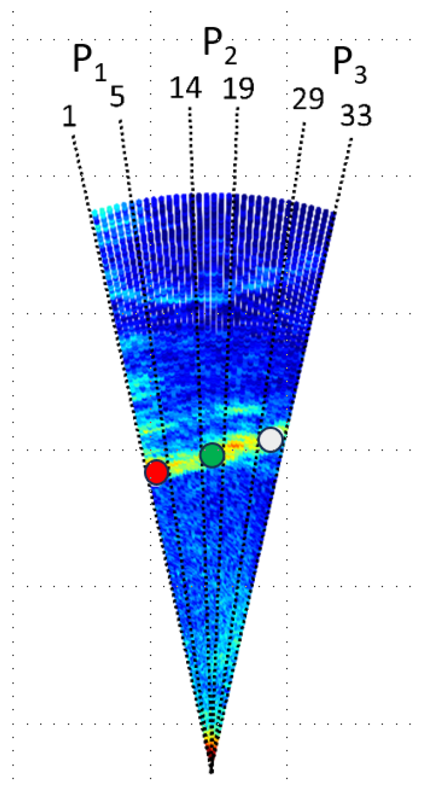
2.3.2. Estimating Orientation and Distance to a Wall

This procedure was developed to estimate the relative orientation and distance of the HROV with respect to the walls of a polygonal pool. In particular, it is intended to use the wall directly facing the vehicle. To accomplish this goal, the sonar scanning angle is limited to the front sector of the vehicle, covering a 30 range, as shown in Figure 10. Limiting the scanning angle has a beneficial impact from a control perspective, as it reduces the sonar reading time to approximately 1.50 s.
The vehicle’s orientation is defined by angle α (see Figure 10a), which is determined through the following procedure. Triangle P 1 P 3 P 4 is similar to triangle P 1 P 2 P 5 (Figure 10b), and thus, α is equivalent to angle P 1 P 3 P 4 . Consequently, the value of α can be derived from the coordinates of points P 1 and P 3 . Let [ x p 1 , y p 1 ] and [ x p 3 , y p 3 ] be the coordinates of P 1 and P 3 expressed in the vehicle’s local frame. Given that the coordinates of P 4 are [ x p 1 , y p 3 ] , α can be calculated as follows:
α = a t a n 2 ( y P 1 y P 3 , x P 3 x P 1 ) .
To define points P 1 , P 2 and P 3 , the measurements obtained from the sonar are applied by employing the subsequent methodology. The coordinates of each point P i are determined by averaging the coordinates of the points with the highest echo intensity from a set of beams. Considering that for beam j, the point with the highest echo intensity ( P j m ) matches with a point on the pool wall (assuming no intermediate obstacles), the coordinates of this point [ x j m , y j m ] can be defined as
x j m = d j · cos θ j     y j m = d j · sin θ j ,
where d j represents the distance from the vehicle to the point of maximum echo, and θ j corresponds to the angle associated with beam j.
Based on that definition, the coordinates of point P i ( [ x P i , y P i ] ) are calculated using the following expressions:
x P i = j = n 0 n f x j m n f n 0     y P i = j = n 0 n f y j m n f n 0 ,
where n 0 and n f represent the number of the initial and final beams in the set of the beams under consideration, respectively. In this approach, to determine the coordinates of point P 1 , the measurements from beams numbered 1 to 5 are taken into account. In the case of P 2 , the beams considered are those ranging from 14 to 19, and beams from 29 to 33 are utilized to determine the coordinates of P 3 (refer to Figure 11).
From these values, the coordinates of P 1 and P 3 are obtained and, employing Expression (1), it becomes feasible to calculate angle α . Finally, the distance of the vehicle to the wall is determined by calculating the x coordinate of P 2 using the same equations.

2.4. Automatic Control Module

The control of the vehicle is structured into two levels, one concerning the Automatic execution of the task and the other related to the control of the HROV’s spatial evolution. The subsequent sections detail their main characteristics. It is worth emphasizing that the proposal described in this article seeks to demonstrate the feasibility of extending the concept of reactive navigation, widely employed in UGVs, to the navigation of HROV systems. In this sense, the information used at each moment to control the HROV’s motion relies exclusively on data derived from the sonar sensor, with no other data sources being utilized for this purpose, including the IMU measurements, which are solely recorded for verification.
It should be noted that this module exclusively controls movement in the horizontal plane, while depth control is executed directly by Pixhawk based on data from the Ping Echosounder sensor. It is relevant to highlight that the system carries out this last operation even when working in the traditional ROV mode.

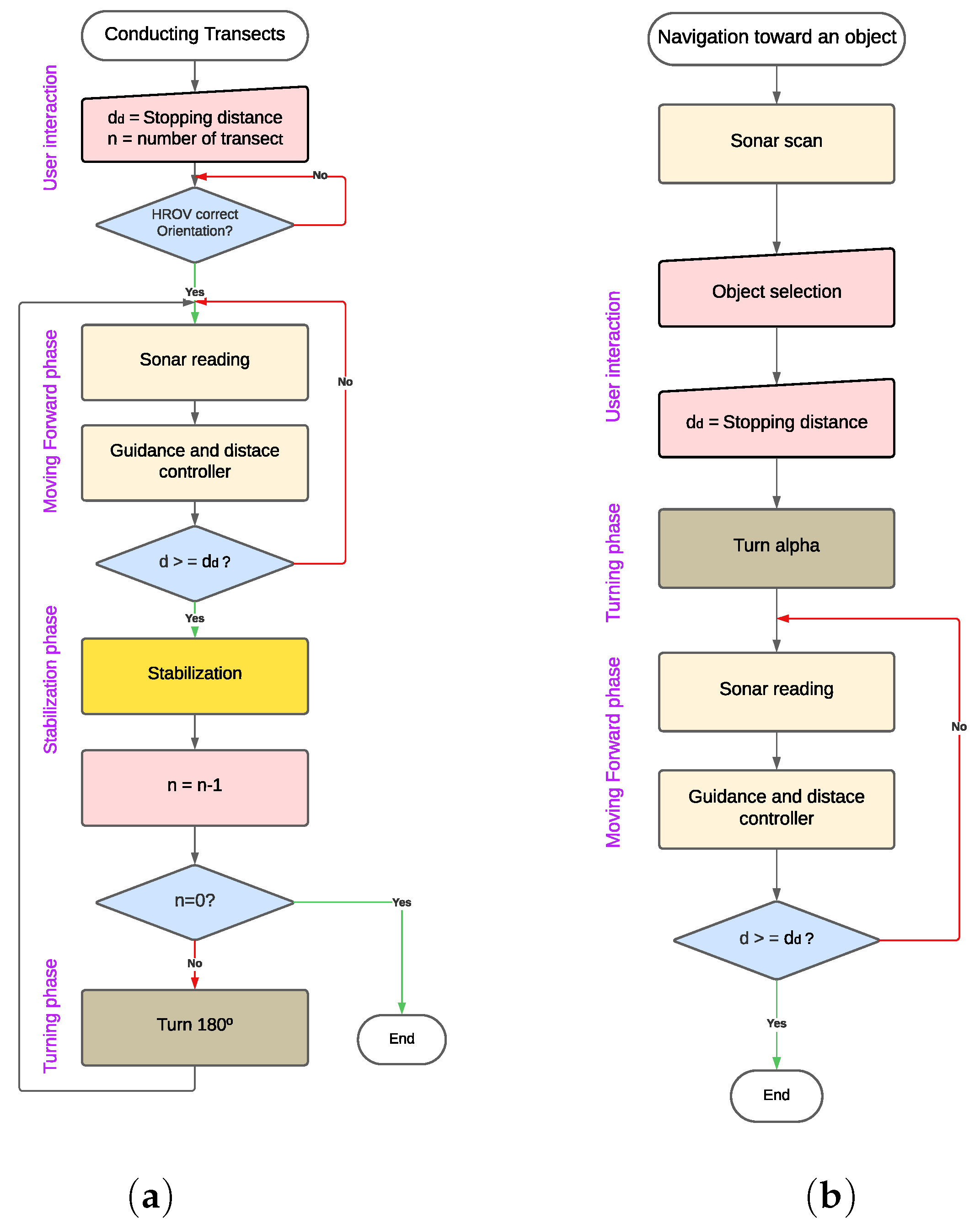
2.4.1. Automatic Task Execution

Two different task controllers have been developed, each tailored to one of the two applications proposed within this work. These controllers exhibit a discrete nature, they are responsible for activating and deactivating the orientation adjustments and movement operations in response to various events occurring during task execution.
Conducting Transects
This application is designed for the purpose of navigating the HROV along successive transects that are oriented perpendicular to the walls facing the vehicle. In this scenario, the user is responsible for initially positioning the vehicle facing the wall toward the HROV is intended to navigate, establishing the number of transects the vehicle executes, and specifying the distance from the wall at which the vehicle halts, turns, and initiates the next transect. The operational procedure of this controller is described in the flowchart depicted in Figure 12a. According to this scheme, once the user inputs operation-related data and places the HROV accordingly, the controller initiates an iterative loop.
Firstly, the “moving forward” phase is initiated. During this phase, values regarding orthogonality and distance to the front wall are estimated using sonar scans. Subsequently, control actions aimed at maintaining orthogonality and facilitating forward motion are executed, with these actions being determined by the guidance and Forward Distance Controller, as detailed in the subsequent section. Following this, the system verifies whether the HROV reaches the user-defined distance from the wall. If not, the system iteratively repeats the sequence of reading sonar data and executing control actions.
After reaching the specified distance, a “stabilization phase” is activated, where the vehicle remains stationary while rectifying any potential disorientation that may have occurred during the deceleration process. Once the vehicle is stabilized, the counter variable, responsible for tracking the number of transects to be conducted, is decremented. If the counter value is not equal to zero, the vehicle proceeds with a 180 turn (the “turning phase”) and starts the process again, navigating the transect in the opposite direction. In the case when the counter value equals to zero, the operation is considered finished.
Navigation toward a selected object
This application is aimed to provide the user with the capability to select an object of interest from a group of objects detected in a sonar reading and navigate the HROV until it stops at a specified distance from the obstacle. The operational process of this controller is displayed in Figure 12b. Following this scheme, after the sonar provides a measurement and detects obstacles within the scene, the operator is tasked with object selection and the indication of the stopping distance. Subsequently, the OCM computes the relative angle ( α ) between the HROV and the selected object. Then, the vehicle performs a turning maneuver (“turning phase”) to orient itself toward the chosen target. In the “moving forward phase”, successive sonar readings are utilized to determine the distance and orientation of the object in relation to the HROV, enabling the application of control actions to facilitate the approach to the target while maintaining alignment with it. Finally, when the predetermined distance is achieved, the vehicle stops and the operation finishes.

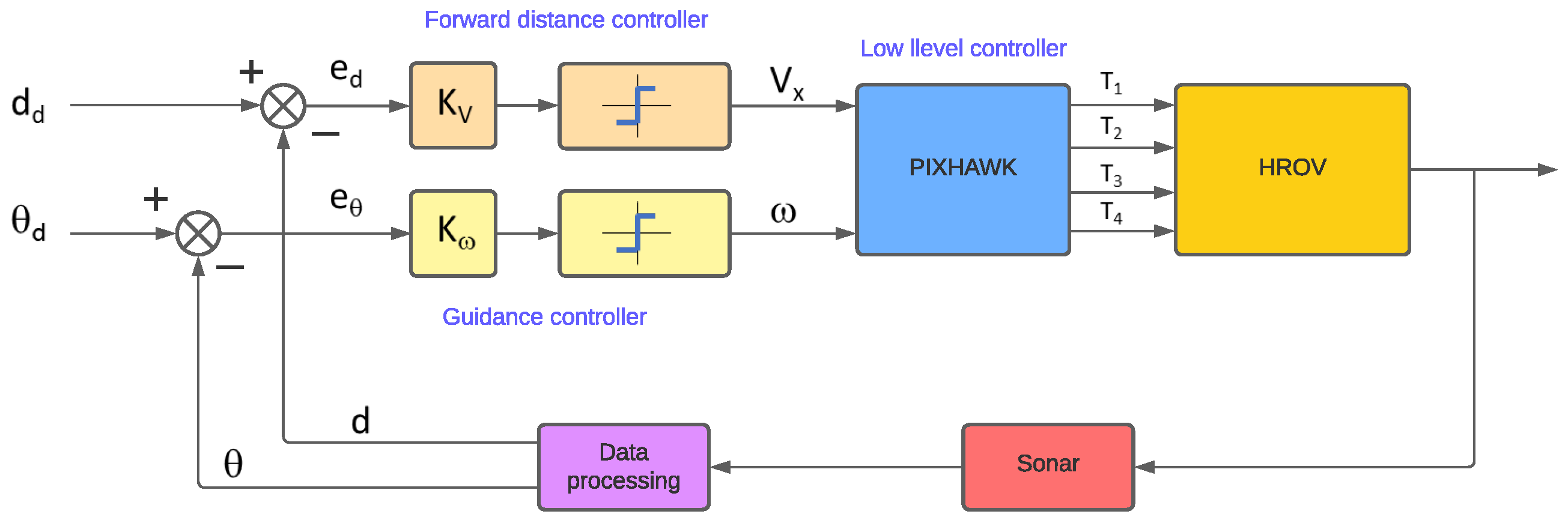
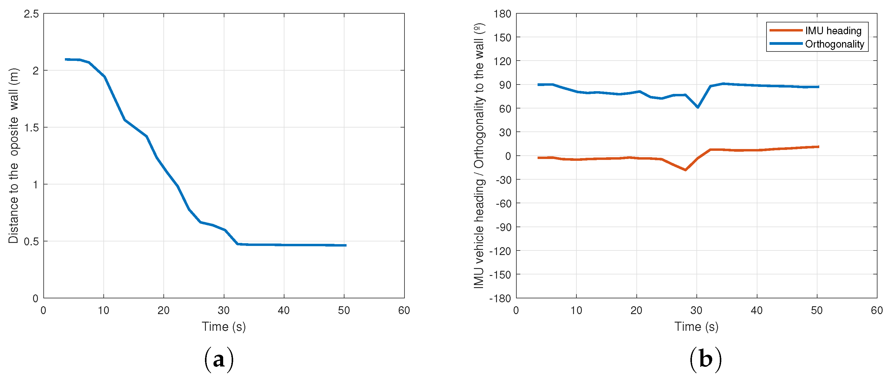
2.4.2. Guidance and Forward Distance Controller

In order to develop this control module, the capability of the Pixhawk system to manipulate the thrust of each of the four horizontal motion thrusters is used. The particular configuration of these four thrusters (see Figure 1b) enables decoupling the control for linear and angular velocities by generating different rotation and linear speed values independently. More precisely, the system allows the simultaneous specification of the linear velocity components ( V x and V y ) within the local frame of the HROV (allowing determination of the frontal and lateral velocity of the vehicle), and the yaw rate, ω , intended to change the orientation of the vehicle. For the applications described in this paper, only the values of V x and ω are designated. Based on this idea, the present approach proposes the development of two independent control actions responsible for steering the system to specific spatial configurations. Particularly, one action is designed to supervise the guidance of the HROV by regulating the vehicle’s orientation, while the other manages the forward movement by taking into account the distance to the opposite wall. Figure 13 displays a block diagram detailing the operation of this control strategy.
The most significant novelty of this proposal is based on the fact that the values of the two controlled variables are determined from the measurements provided by the sonar as described in Section 2.3.2. In both cases, proportional controllers with saturation are employed. The frontal distance control action operates consistently across both applications, governing the approach speed of the HROV toward the opposing target by providing a value of V x proportional to the error between the current distance from the opposite target, d, and the predetermined stopping distance, d d (see Figure 13).
The guidance control action, on the other hand, provides a value of ω proportional to the deviation of the vehicle’s orientation from the desired state (error in orientation). Hence, its responsibility lies in preserving the orthogonality of the HROV concerning the opposing wall, in the case of the “conducting transect” application, and ensuring the alignment of the HROV with the chosen object, as seen in the “navigation towards an object” application.
Tuning the gains of the two control actions replicates the functionality of adaptive controllers created through the gain scheduling technique [46]. In both cases, the proportional constant’s value changes based on the orientation error, e θ , in accordance with the following expressions:
K v = K v 1 i f e θ < T h θ K v 2 i f e θ T h θ     K ω = K ω 1 i f e θ < T h θ K ω 2 i f e θ T h θ .
This strategy is designed to mitigate the risk of significant orthogonality deviation leading to system destabilization. Consequently, when the orientation error ( e θ ) exceeds a predefined threshold ( T h θ ), the speed gain is reduced, giving higher priority to orientation control. Likewise, under these conditions, the guidance control gain is also lowered, resulting in a less aggressive control action. Consequently, during substantial disorientation, the HROV moves and turns at a slower velocity. When e θ falls below T h θ , the speed increases, and the higher guidance gain compensates for the reduced error value.
In the case of the 180 rotation maneuver during the “turning phase”, the application of the guidance controller is not feasible, since the method provides orthogonality values concerning the opposing wall, while the objective during this phase is to achieve orthogonality with respect to the rear wall. To address this limitation, the control of this rotation is executed through an open-loop strategy. Once a specific yaw rate is established, an estimation is made regarding the approximate time required for the HROV to complete the required 180 rotation. Consequently, after the calculated time period, the vehicle changes its orientation; nevertheless, it is not precisely aligned as required. However, at that moment, a phase transition is triggered, and the previously described guidance control action comes into play, assuming the responsibility for steering the vehicle’s orientation closer to the desired value.

3. Results

This section is devoted to presenting the experimental results that validate the feasibility and efficiency of the approach addressed in this article. First of all, results regarding the control of the orientation of the vehicle in relation to the walls of the pool are presented. Secondly, the efficiency of the system for conducting transects was tested. Finally, experiments related to navigation toward a selected object are illustrated.
Although the orientation control is executed solely based on the estimation of the relative orientation derived from the sonar measurements, the orientation provided by the vehicle’s IMU is simultaneously tracked. This concurrent monitoring aims to verify the correctness of the evolution of the estimated orientation. In the experiments shown below, the values of controller gains are K v 1 = 0.3 , K v 2 = 0 , K ω 1 = 4.5 , K ω 2 = 1.5 , with T h θ = 15 . Nevertheless, these values depend greatly on the particular calibration of the low-level controller.
While the applications described in this article were developed for use in turbid water environments, the experiments presented below were conducted in a pool with clear water. This approach allowed for visual observation and recording of the HROV’s behavior, confirming the proper execution of predefined operations. It is important to note that water clarity is irrelevant for the designed algorithms. In reference [47], a video is available displaying images recorded during the experiments presented in this section.

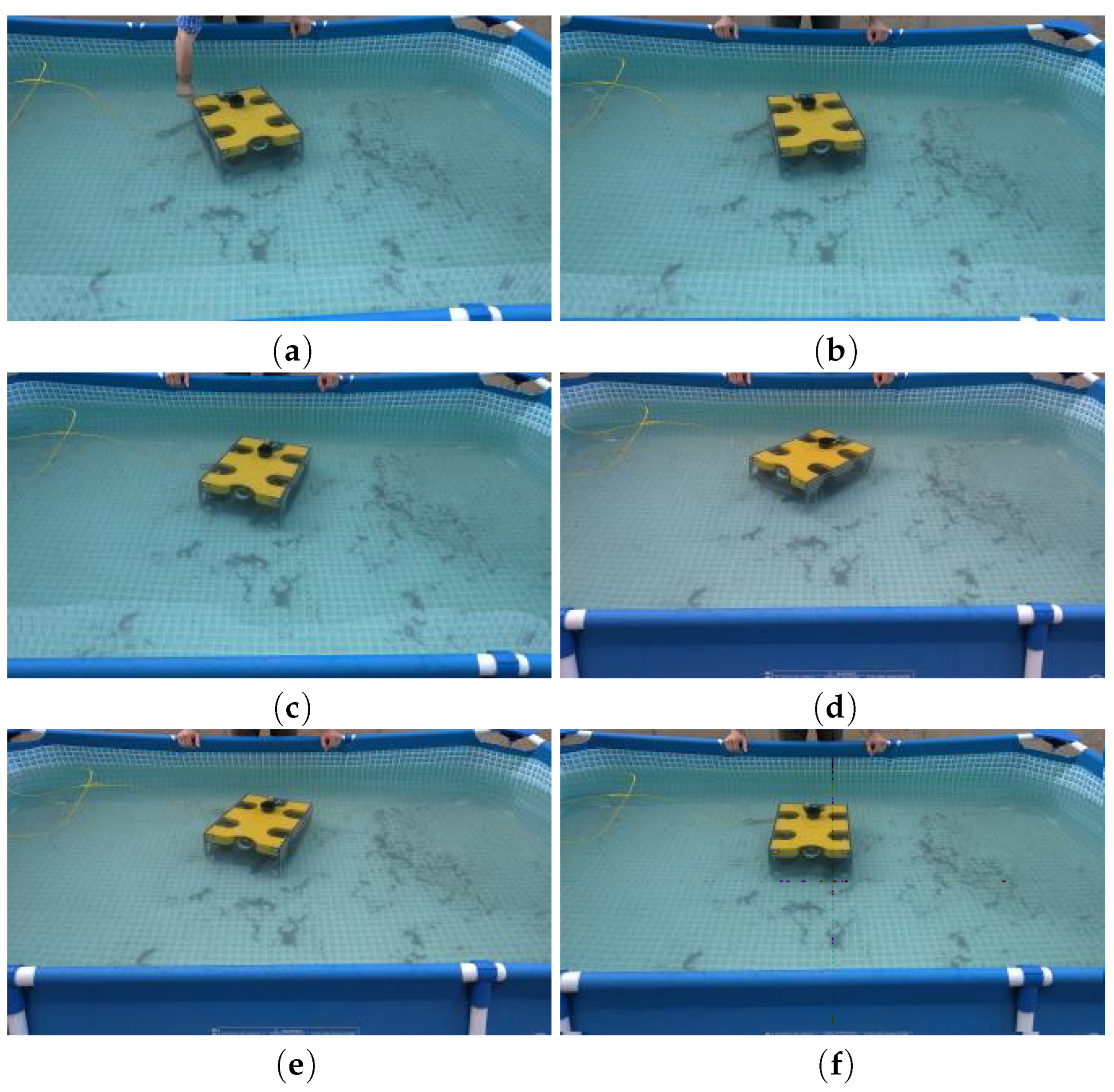
3.1. Controlling Vehicle Orientation

The first experimental assessment focused on evaluating the vehicle’s capability to maintain orthogonality with respect to the opposing wall of the pool while the vehicle was kept stationary, using only the guidance control action. In this experiment, the vehicle was positioned at a predefined distance from the pool’s wall, with the local X-axis initially set perpendicular to the wall. Manual perturbations were introduced in this scenario, as depicted in Figure 14a. The heading control demonstrated effective performance in restoring the vehicle to its initial orientation. Figure 15a shows the comparison between the vehicle’s orthogonality as determined by the sonar measurements and the heading value provided by the IMU. Following manual perturbation, the vehicle oscillates before stabilizing in the orthogonal configuration. Figure 15b illustrates the difference between both values. As expected, this difference remains minimal when the vehicle is in close proximity to orthogonality but increases when the angular distance to orthogonality exceeds approximately 15 .
However, from the control perspective, this experiment demonstrates that the proposed controller effectively stabilizes the vehicle in the orthogonal configuration within a reasonable period of time. Although achieving complete homogenization of manual perturbations across different experiments is challenging, the average stabilization time considering the experiment with manual perturbations was determined to be approximately 17 s.

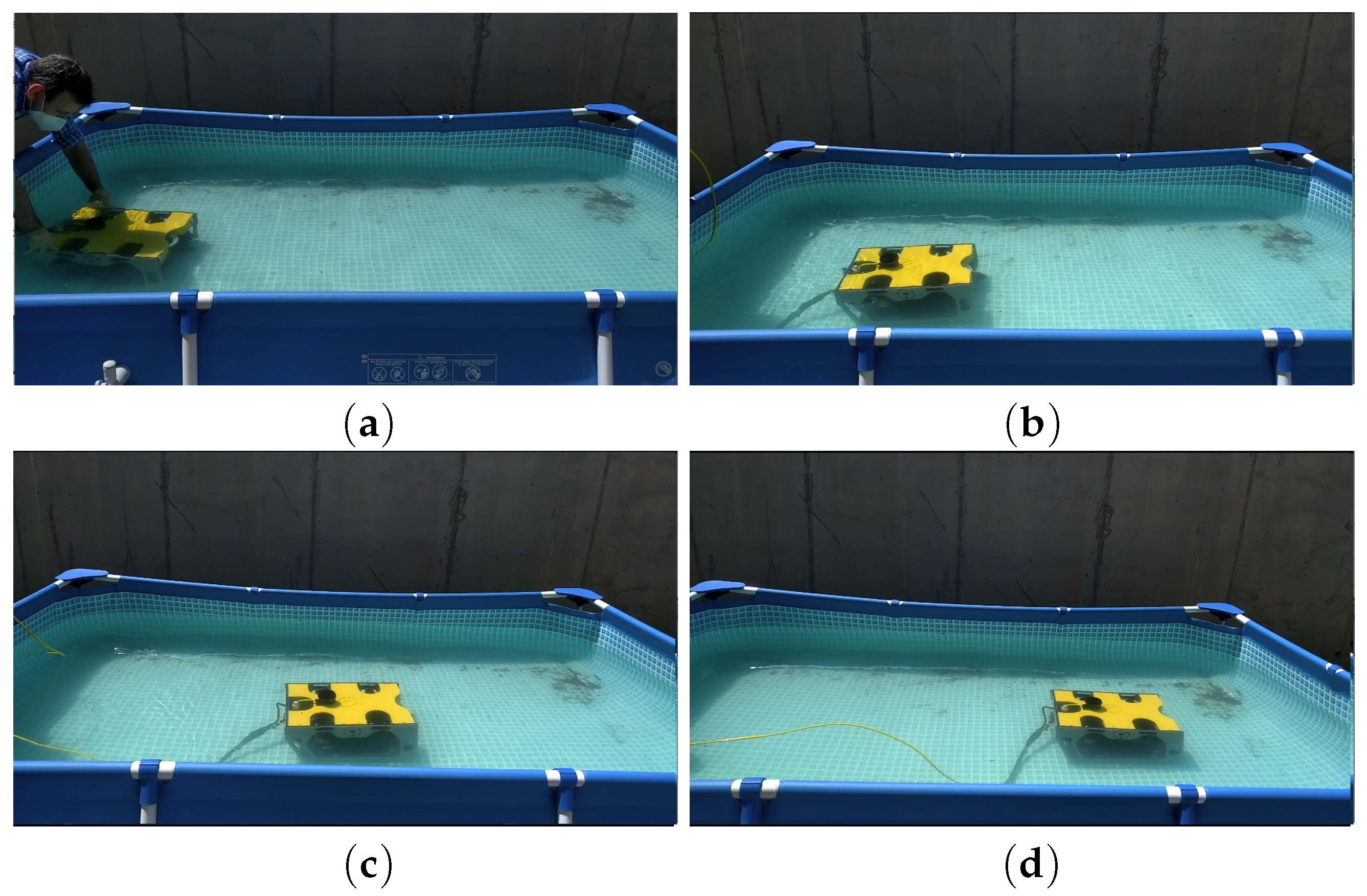
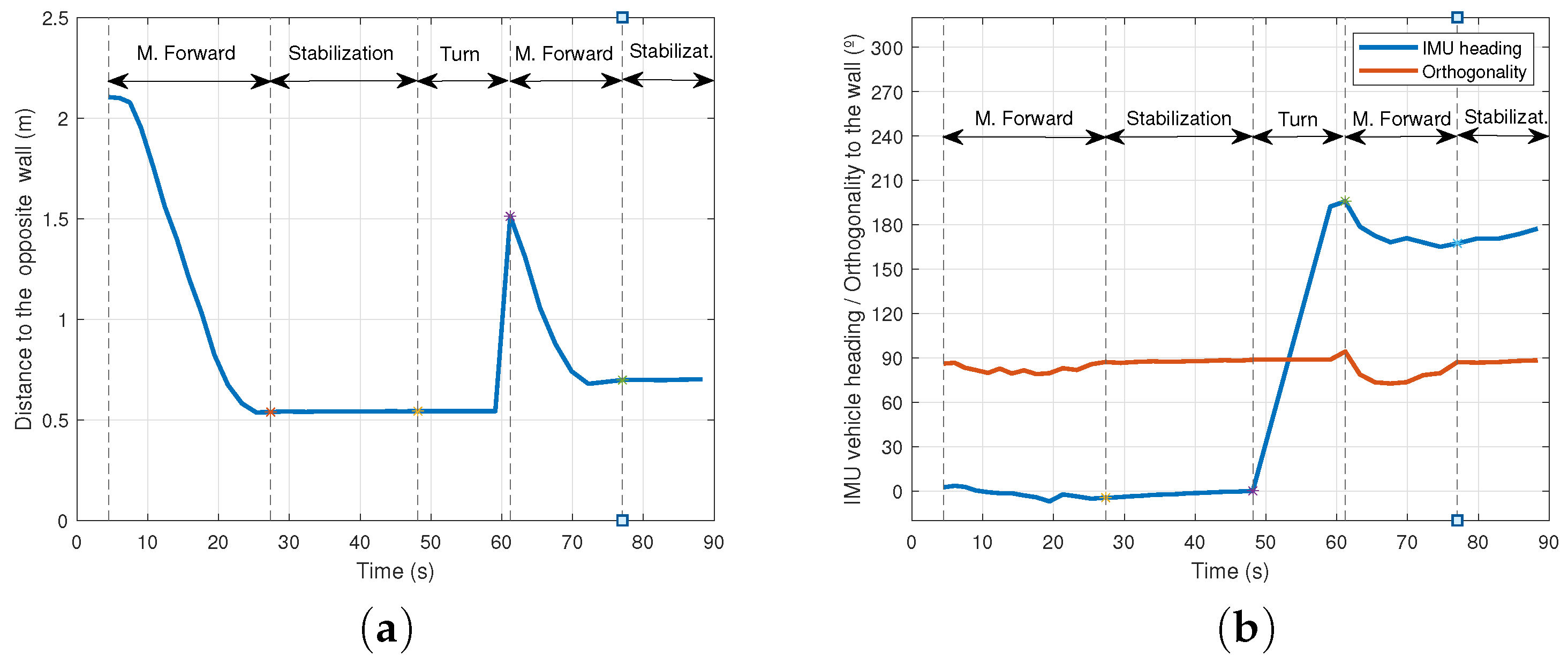
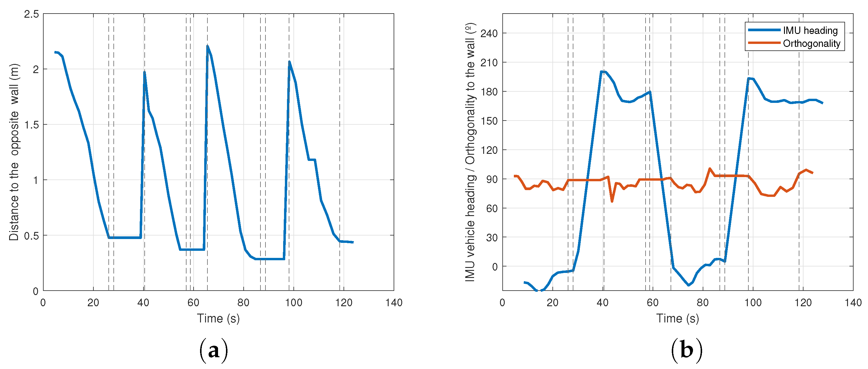
3.2. Conducting Transects

The second set of experiments was designed to test the vehicle’s reactivity in navigation by conducting transects.
During these experiments, the conducting transect application was running, and the different phases of the flowchart of Figure 12a could be identified. While the watercraft moved forward, the guidance and the forward distance control actions operated simultaneously. Thus, in this scenario, the control system is required to concurrently compute both the distance and the angle relative to the wall, and subsequently adjust the appropriate forward and turning speeds.
Figure 16a–d display selected snapshots captured during an experiment cursing one transect. Figure 17a shows the distance to the opposite wall versus time during this experiment, while Figure 17b illustrates the evolution of the angle relative to the opposite wall estimated from the sonar data, and the evolution of the heading obtained from the IMU.
As observed in Figure 17a, the HROV advances until it reaches a certain distance from the wall, at which point it stops. During this phase, the distance to the opposing wall decreases as the vehicle moves forward, and stabilizes when the HROV stops. Regarding Figure 17b, a final deviation is apparent, mainly due to vehicle deceleration, although the vehicle eventually stabilizes correctly at around 90 . A similar interpretation can be made when analyzing the angle provided by the IMU, which validates the consistency of the obtained results.
The next experiments are similar to the previous one, with the difference that once the HROV stabilizes in front of the wall, it turns 180 and subsequently moves towards the opposing wall. Figure 18a–d illustrate four specific moments extracted from an experiment conducted during several transects.
Figure 19a,b present the temporal evolution of the three main parameters (distance to the opposite wall, orthogonality and heading) throughout experimental trials where the vehicle executed two transects. These figures also illustrate the three different states of the controller.
In the initial state, the vehicle proceeds forward while attempting to maintain orthogonality with the opposing wall. In the second state, the vehicle stops and stabilizes its orientation. The third state involves executing a turning maneuver to orient the HROV towards the wall situated behind it. Following the rotating maneuver, the controller starts the “move forward” phase again, as this experiment involves the execution of two successive transects. During the stabilization and turning phases, the estimations of the distance to the opposite wall are discarded. Consequently, in both phases, this variable is recorded as a constant value. The same happens with the orthogonality value which stops being estimated in the rotating phase.
Figure 20a,b depict the results of a four transects experiment. It is evident that the data exhibit results similar to those presented above, demonstrating the correct performance of the proposed approach to implement reactive navigation based on the information computed from the sonar signal in long-term application.

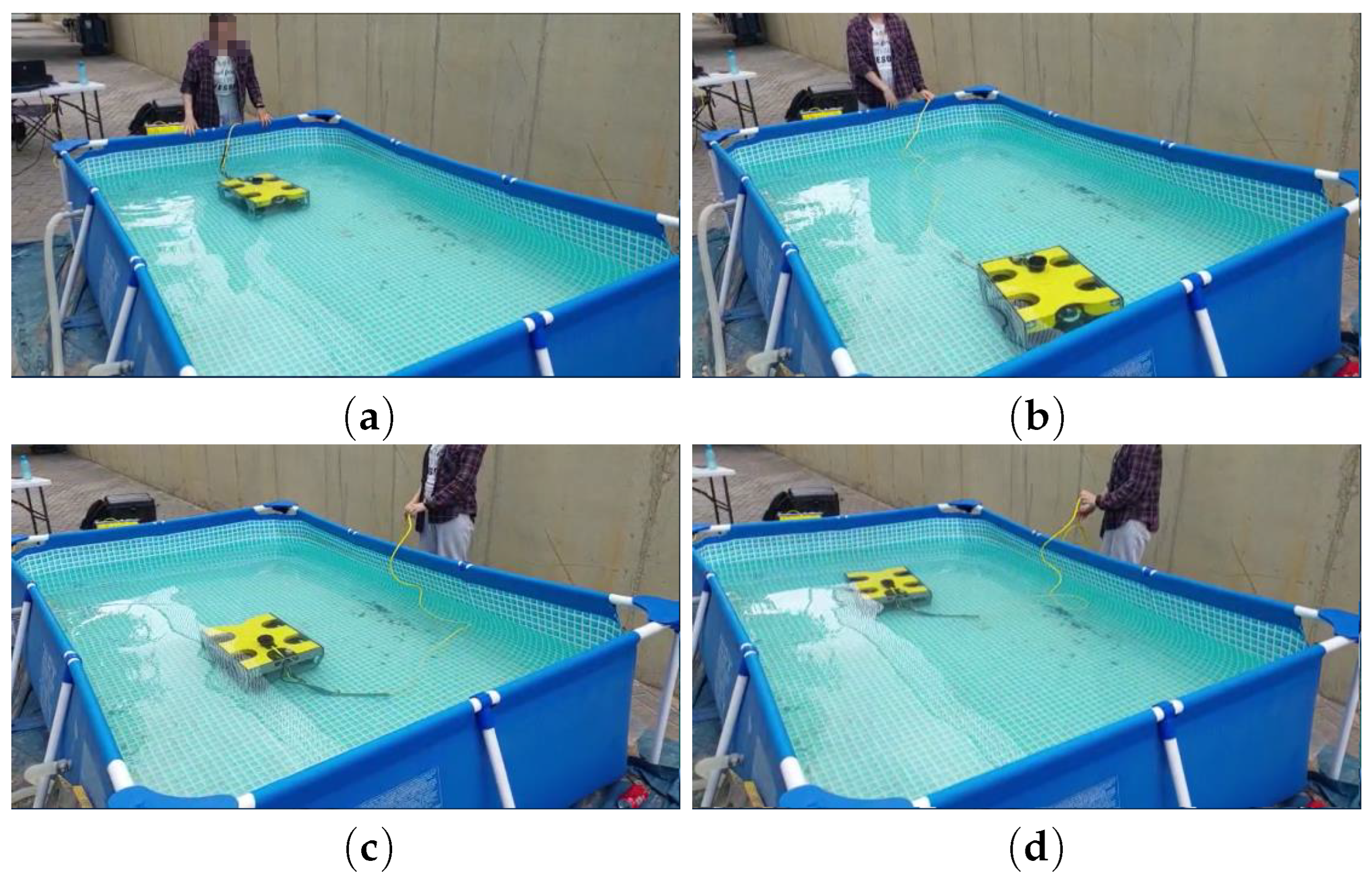
3.3. Navigation toward a Selected Object

In these experiments, the navigation toward a selected object application is tested. In this case, the objective is to navigate the HROV in a specified direction until reaching a predefined distance from the selected object. Selection of the target is performed by the operator among various objects that were identified by the SIM. From this moment, the HROV, autonomously, rotates to face the selected object and move forward until reaching a specific distance from the target. Figure 21a displays the image provided to the user after a sonar scan. The objects identified within the image are numbered, facilitating the selection of a specific target for navigation by simply selecting the corresponding number. In this test, only one object is placed within the pool, while the rest of the identified objects are positioned outside the pool. Due to the nature of the pool being fabric-based, the sonar signal extends beyond its boundaries, enabling nearby objects to be identified. Specifically, in this test, the chosen object is denoted with the number “5”.
After selecting the object, angle α (Figure 21b) is computed to determine the required rotation for the HROV. This rotation aims to align the “x” axis of the HROV’s local frame with the target. In Figure 21b, the target’s position vector concerning the HROV’s local frame is defined by taking into account the centroid associated with the cluster labeled as “5” (representing the selected object).
Figure 22 shows four snapshots taken during the experimental trials, where once the target is selected, the HROV rotates until it faces the object, Figure 22a,b, and navigates towards the target until reaching the correct distance; Figure 22c,d.
Figure 23 presents the temporal evolution of the three main parameters involved in the navigation of the HROV. This evolution closely resembles the structures illustrated in the previous section. As a particular feature of the second phase, the navigation process is aimed at maintaining the selected object aligned with the forward direction of the HROV, i.e., α is maintained close to zero rather than trying to keep vehicle’s orthogonality with respect to the wall. In the experiment of Figure 22, the initial value of α was around 130 .
Similar to the preceding tests, during the rotation phase, distance, heading and orientation are not recorded. These parameters are updated again when the rotation phase concludes and forward motion starts. We observe that the distance to the obstacle (Figure 23a) presents a slight decrement when the vehicle concludes the turning maneuver. Once the HROV aligning itself with the object, it begins the forward navigation phase, at which point the distance begins to decrease at a constant rate. Meanwhile, due to disturbances, heading suffers slight fluctuations, but α keeps values close to zero (Figure 23b).

4. Discussion and Conclusions

This article introduced a control architecture that successfully transforms a small-scale commercial ROV into a Reactive HROV capable of autonomously executing tasks that require reactive navigation, particularly designed for environments with limited visibility. The hybrid nature of the system enables the user to intervene in the operation execution either at a high level, setting different task parameters, or at a low level, assuming complete control of the mission by teleoperating the watercraft. The architecture relies on sonar sensor data to comprehend the robot’s surroundings, and processing these data to facilitate task execution. The discrete event controller, responsible for activating or deactivating guidance and distance controller, ensures that the robot moves effectively during operation performance.
In this context, two applications were developed, inspired by the typical monitoring and maintenance tasks that are usually carried out in outdoor aquaculture farms, where the turbidity of the water represents a challenge when controlling a watercraft.
Experimental results demonstrate the feasibility of the proposed architecture. The potential for further enhancement exists, particularly in the field of control strategies, such as incorporating integral or derivative actions, and exploring advanced strategies like optimal or predictive control. However, these advancements may face challenges, primarily due to the time delay introduced by sonar scanning, which could impact system stability.
Additionally, the architecture opens doors to expanding the range of applications. Future work could involve tasks related to element search or identification, tailored for specific characteristics, and operations in pools with diverse geometries.
This study validates the initial hypothesis that it is feasible to convert a commercial ROV into a Reactive HROV by implementing a control architecture without requiring structural modifications. This enables the execution of reactive tasks solely based on sonar data. Significantly, this article introduces a new dimension compared to the existing literature, since it addresses different problems and employs novel approaches not previously proposed.

Author Contributions

Conceptualization: F.G.-B. and A.G.-C.; methodology: F.G.-B., A.G.-C. and O.M.-C.; software, A.G.-C. and O.M.-C.; experimentation: A.G.-C., O.M.-C. and F.G.-B.; validation: F.G.-B., I.P.-C. and A.P.-R.; formal analysis, F.G.-B. and A.G.-C.; investigation: F.G.-B., J.C.G.-E. and A.P.-R.; resources: F.G.-B., I.P.-C. and A.P.-R.; data curation: F.G.-B. and O.M.-C.; writing—original F.G.-B., A.G.-C., O.M.-C. and J.C.G.-E.; visualization: A.P.-R., I.P.-C. and J.C.G.-E.; supervision, F.G.-B.; project administration: J.C.G.-E. and I.P.-C.; funding acquisition: J.C.G.-E. and I.P.-C. All authors have read and agreed to the published version of the manuscript.

Funding

This research was funded by KTTSeaDrones project (0622_KTTSEADRONES_5E), cofunded by the European Regional Development Fund, ERDF, through the Interreg V-A Spain-Portugal program (POCTEP) 2014–2020.

Data Availability Statement

All the related data have been provided within the paper.

Conflicts of Interest

The authors declare no conflict of interest. The funders had no role in the design of the study; in the collection, analyses, or interpretation of data; in the writing of the manuscript; or in the decision to publish the results.

References

  1. Petillot, Y.R.; Antonelli, G.; Casalino, G.; Ferreira, F. Underwater robots: From remotely operated vehicles to intervention-autonomous underwater vehicles. IEEE Robot. Autom. Mag. 2019, 26, 94–101. [Google Scholar] [CrossRef]
  2. Sánchez, P.; Papaelias, M.; Márquez, F. Autonomous underwater vehicles: Instrumentation and measurements. IEEE Instrum. Meas. Mag. 2020, 23, 105–114. [Google Scholar] [CrossRef]
  3. Ramírez, I.S.; Bernalte Sánchez, P.J.; Papaelias, M.; Márquez, F.P.G. Autonomous underwater vehicles and field of view in underwater operations. J. Mar. Sci. Eng. 2021, 9, 277. [Google Scholar] [CrossRef]
  4. Karlsen, H.; Amundsen, H.; Caharija, W.; Ludvigsen, M. Autonomous Aquaculture: Implementation of an autonomous mission control system for unmanned underwater vehicle operations. In Proceedings of the OCEANS 2021: San Diego–Porto, San Diego, CA, USA, 20–23 September 2021; pp. 1–10. [Google Scholar]
  5. Osen, O.L.; Sandvik, R.I.; Rogne, V.; Zhang, H. A novel low cost ROV for aquaculture application. In Proceedings of the OCEANS 2017-Anchorage, Anchorage, AK, USA, 18–21 September 2017; pp. 1–7. [Google Scholar]
  6. Huvenne, V.A.I.; Robert, K.; Marsh, L.; Iacono, C.L.; Bas, T.L.; Wynn, R.B. ROVs and AUVs. In Submarine Geomorphology; Springer International Publishing: Cham, Switzerland, 2018; pp. 93–108. [Google Scholar]
  7. Balaban, M.O.; Soriano, M.G.; Ruiz, E.G. Using image analysis to predict the weight of Alaskan salmon of different species. J. Food Sci. 2010, 75, 157–162. [Google Scholar] [CrossRef] [PubMed]
  8. Página Oficial de la Unión Europea. Available online: https://ec.europa.eu/commission/presscorner/detail/en/IP_12_955 (accessed on 30 October 2023).
  9. Serpa, D.; Ferreira, P.; Ferreira, H.; Fonseca, L.C.; Dinis, M.T.; Duarte, P. Modelling the growth of white seabream and gilthead seabreamin semi-intensive earth production ponds using the Dynamic Energy Budget approach. J. Sea Res. 2013, 76, 135–145. [Google Scholar] [CrossRef]
  10. Gutiérrez-Estrada, J.C.; Pulido-Calvo, I.; Castro-Gutiérrez, J.; Peregrín, A.; López-Domínguez, S.; Gómez-Bravo, F.; Garrocho-Cruz, A.; Rosa-Lucas, I. Fish abundance estimation with imaging sonar in semi-intensive aquaculture ponds. Aquac. Eng. 2022, 97, 102235. [Google Scholar] [CrossRef]
  11. Gutiérrez-Estrada, J.C.; de Pedro, E.; López-Luque, R.; Pulido-Calvo, I. Comparison between traditional methods and artificial neural networks for ammonia concentration forecasting in an eel intensive rearing system. Aquac. Eng. 2004, 31, 183–203. [Google Scholar] [CrossRef]
  12. Oficial Web Page of SINTEF. Available online: https://www.sintef.no/en/ (accessed on 30 October 2023).
  13. Oficial Web Page of SIMRAD Subsea. Available online: https://www.kongsberg.com/es/maritime/contact/simrad/ (accessed on 30 October 2023).
  14. Klepaker, R.; Vestgå, K.; Hallset, J.; Balchen, J. The application of a free-swimming ROV in aquaculture. IFAC Proc. Vol. 1987, 20, 181–185. [Google Scholar] [CrossRef]
  15. Karpov, K.; Bergen, M.; Geibel, J. Monitoring fish in California Channel Islands marine protected areas with a remotely operated vehicle: The first five years. Mar. Ecol. Prog. Ser. 2012, 453, 159–172. [Google Scholar] [CrossRef]
  16. Rundtop, P.; Frank, K. Experimental evaluation of hydroacoustic instruments for ROV navigation along aquaculture net pens. Aquac. Eng. 2016, 74, 143–156. [Google Scholar] [CrossRef]
  17. Osen, O.; Leinan, P.; Blom, M.; Bakken, C.; Heggen, M.; Zhang, H. A novel sea farm inspection platform for norwegian aquaculture application. In Proceedings of the OCEANS 2018 MTS/IEEE Charleston, Charleston, SC, USA, 22–25 October 2018; pp. 1–8. [Google Scholar]
  18. Gómez Bravo, F.; Garrocho Cruz, A.; Gutiérrez Estrada, J.C.; Pulido Calvo, I.; Peregrín Rubio, A.; López Domínguez, S.; Castro Gutiérrez, J. Processing acoustic images for the exploitation of fish farms. Instrum. Viewp. 2023, 22, 69–70. [Google Scholar]
  19. Centelles, D.; Soriano, A.; Marin, R.; Sanz, P. Wireless HROV Control with Compressed Visual Feedback Using Acoustic and RF Links. J. Intell. Robot. Syst. 2020, 99, 713–728. [Google Scholar] [CrossRef]
  20. Sánchez, J. Towards a Multimodal Interface for the Specification of Intervention Tasks in Underwater Robotics. Ph.D. Thesis, Universitat Jaume I, Castellón de la Plana, Spain, 2021. [Google Scholar]
  21. Oficial Web Page of Double Eagle Sarov. Available online: https://www.saab.com/products/doubleeagle (accessed on 30 October 2023).
  22. Oficial Web Page of Nereus. Available online: https://www.whoi.edu/oceanus/feature/new-hybrid-deep-sea-vehicle-is-christened-nereus/ (accessed on 30 October 2023).
  23. IEEE Web Page of Aquanaut. Available online: https://spectrum.ieee.org/meet-aquanaut-the-underwater-transformer (accessed on 30 October 2023).
  24. Web Page of Ocean One. Available online: https://khatib.stanford.edu/ocean-one.html (accessed on 30 October 2023).
  25. Web Page of HROV-Arch. Available online: https://robotik.dfki-bremen.de/en/research/projects/hrov-arch (accessed on 30 October 2023).
  26. Web Page of MERBOTS. Available online: https://www.irs.uji.es/merbots/welcome-merbots-project-website (accessed on 30 October 2023).
  27. Oficial Web Page of KTTSeaDrones. Available online: https://kttseadrones.wixsite.com/kttseadrones (accessed on 30 October 2023).
  28. Oficial Web Page of Pixhawk. Available online: https://pixhawk.org/ (accessed on 30 October 2023).
  29. IEEE Web Page of Qgroundcontrol. Available online: http://qgroundcontrol.com/ (accessed on 30 October 2023).
  30. Oficial Web Page of Mavlink Protocol. Available online: https://mavlink.io/en/ (accessed on 30 October 2023).
  31. Oficial Web Page of Ardusub. Available online: https://www.ardusub.com/ (accessed on 30 October 2023).
  32. Oficial Web Page of Ardupilot. Available online: https://ardupilot.org/ (accessed on 30 October 2023).
  33. Feng, L.; Fangchao, Q. Research on the hardware structure characteristics and EKF filtering algorithm of the autopilot PIXHAWK. In Proceedings of the 2016 Sixth International Conference on Instrumentation & Measurement, Computer, Communication and Control (IMCCC), Harbin, China, 21–23 July 2016; pp. 228–231. [Google Scholar]
  34. Technical Guide Web Page of Ping Echosounder Sonar. Available online: https://bluerobotics.com/learn/ping-sonar-technical-guide/ (accessed on 30 October 2023).
  35. Oficial Web Page of Ping360. Available online: https://bluerobotics.com/store/sonars/imaging-sonars/ping360-sonar-r1-rp/ (accessed on 30 October 2023).
  36. Whitcomb, L.; Jakuba, M.; Kinsey, J.; Martin, S.; Webster, S.; Howl, J.; Taylor, C.; Gomez-Ibanez, D.; Yoerger, D. Navigation and control of the Nereus hybrid underwater vehicle for global ocean science to 10,903 m depth: Preliminary results. In Proceedings of the 2010 IEEE International Conference on Robotics and Automation, Anchorage, AK, USA, 3–7 May 2010; pp. 594–600. [Google Scholar]
  37. Johansson, B.; Siesjö, J.; Furuholmen, M. Seaeye Sabertooth, a hybrid AUV/ROV offshore system. In Proceedings of the SPE Offshore Europe Conference and Exhibition, Aberdeen, UK, 6–8 September 2011; p. SPE-146121. [Google Scholar]
  38. Khatib, O.; Yeh, X.; Brantner, G.; Soe, B.; Kim, B.; Ganguly, S.; Stuart, H.; Wang, S.; Cutkosky, M.; Edsinger, A.; et al. Ocean one: A robotic avatar for oceanic discovery. IEEE Robot. Autom. Mag. 2016, 23, 20–29. [Google Scholar] [CrossRef]
  39. Manley, J.; Halpin, S.; Radford, N.; Ondler, M. Aquanaut: A new tool for subsea inspection and intervention. In Proceedings of the OCEANS 2018 MTS/IEEE Charleston, Charleston, SC, USA, 22–25 October 2018; pp. 1–4. [Google Scholar]
  40. Pi, R.; Esteba, J.; Cieslak, P.; Palomeras, N.; Sanz, P.J.; Marín, R.; Ridao, P. OPTIHROV: Optically Linked Hybrid Autonomous/Remotely Operated Vehicle, Beyond Teleoperation in a New Generation of Underwater Intervention Vehicles. In Proceedings of the OCEANS 2023-Limerick, Limerick, Ireland, 5–8 June 2023; pp. 1–7. [Google Scholar]
  41. Hildebrandt, M.; Gaudig, C.; Christensen, L.; Natarajan, S.; Carrio, J.; Paranhos, P.; Kirchner, F. A validation process for underwater localization algorithms. Int. J. Adv. Robot. Syst. 2014, 11, 138. [Google Scholar] [CrossRef]
  42. Sanz, P.J.; Marín, R.; Peñalver, A.; Fornas, D.; Centelles, D. Merbots project: Overal description, multisensory autonomous perception and grasping for underwater robotics interventions. In Proceedings of the Actas De Las XXXVIII Jornadas De Automática, Gijón, Spain, 6–8 September 2017. [Google Scholar]
  43. Cuesta, F.; Ollero, A. Intelligent Mobile Robot Navigation; Springer Science & Business Media: Berlin/Heidelberg, Germany, 2005. [Google Scholar]
  44. Oficial Web Page of Ping Protocol. Available online: https://docs.bluerobotics.com/ping-protocol/ (accessed on 30 October 2023).
  45. Mucherino, A.; Papajorgji, P.; Pardalos, P.; Mucherino, A.; Papajorgji, P.; Pardalos, P. K-nearest neighbor classification. In Data Mining in Agriculture; Springer: New York, NY, USA, 2009; pp. 83–106. [Google Scholar]
  46. Makavita, C.; Nguyen, H.; Ranmuthugala, D. Fuzzy gain scheduling based optimally tuned PID controllers for an unmanned underwater vehicle. Int. J. Conceptions Electron. Commun. Eng. 2014, 2, 7–13. [Google Scholar]
  47. A Control Architecture for Developing Reactive Hybrid ROVs, Experimental Results. Available online: https://youtu.be/Y9xjwm2RRV4 (accessed on 2 November 2023).
Figure 1. Sibiu Pro: (a) generall view; (b) top view.
Machines 12 00001 g001
Figure 2. Sibiu Pro Control Structure.
Machines 12 00001 g002
Figure 3. Sonar sensors: (a) echo sonda Pingsonar; (b) MSIS sonar Ping360; (c) Sibiu Pro and Ping360.
Machines 12 00001 g003
Figure 4. GNC Architecture.
Machines 12 00001 g004
Figure 5. ROV Architecture.
Machines 12 00001 g005
Figure 6. Proposed Architecture.
Machines 12 00001 g006
Figure 7. HROV Control Architecture.
Machines 12 00001 g007
Figure 8. Connection between ACM and Pixhawk.
Machines 12 00001 g008
Figure 9. Object detection: (a) experimental environment; (b) experimental setup; (c) user interface with the detected objects.
Machines 12 00001 g009
Figure 10. Vehicle’s orientation and distance: (a) orientation and distance definition; (b) orientation and distance calculus; (c) image from the Sonar.
Machines 12 00001 g010
Figure 11. Definition of points P 1 , P 2 and P 3 from the beams.
Machines 12 00001 g011
Figure 12. Flowchart: (a) Conducting transect application; (b) Navigation toward a selected object application.
Machines 12 00001 g012
Figure 13. Block diagram: Guidance and Forward Distance Controller.
Machines 12 00001 g013
Figure 14. Sequence where the controller returns the vehicle to the correct orientation after a disturbance (af).
Machines 12 00001 g014
Figure 15. Vehicle’s orientation: (a) vehicle’s orthogonality provided by the sonar and vehicle’s heading provided by the IMU; (b) difference between IMU and sonar.
Machines 12 00001 g015
Figure 16. Sequence of a reactive navigation conducting a transcept (ad).
Machines 12 00001 g016
Figure 17. Reactive navigation: (a) distance to the opposite wall; (b) vehicle’s orthogonality provided by the sonar and vehicle’s heading provided by the IMU.
Machines 12 00001 g017
Figure 18. Reactive navigation sequence composed of several transects (ad).
Machines 12 00001 g018
Figure 19. Reactive navigation, two transects: (a) distance to the opposite wall; (b) vehicle’s orthogonality provided by the sonar and vehicle’s heading provided by the IMU.
Machines 12 00001 g019
Figure 20. Reactive navigation, four transects: (a) distance to the opposite wall; (b) vehicle’s orientation provided by the sonar and vehicle’s heading provided by the IMU.
Machines 12 00001 g020
Figure 21. Sonar image: (a) general view; (b) detail.
Machines 12 00001 g021
Figure 22. Reactive navigation, sequence of a navigation toward an object (ad).
Machines 12 00001 g022
Figure 23. Reactive navigation, four transects: (a) distance to the opposite wall; (b) vehicle’s alignment with the object and vehicle’s heading provided by the IMU.
Machines 12 00001 g023
Table 1. Sibiu Pro features.
FeatureValue
Weight16 kg
Size0.52 × 0.39 × 0.29 m
Maximum Depth300 m
Maximum Speed3 knots (1.54 m/s)
Disclaimer/Publisher’s Note: The statements, opinions and data contained in all publications are solely those of the individual author(s) and contributor(s) and not of MDPI and/or the editor(s). MDPI and/or the editor(s) disclaim responsibility for any injury to people or property resulting from any ideas, methods, instructions or products referred to in the content.

