Abstract
This paper introduces a parameter-estimation-based sensorless adaptive direct voltage maximum torque per ampere (MTPA) control strategy for interior permanent magnet synchronous machines (IPMSMs). In direct voltage control, the motor’s electrical parameters, speed, and rotor position are of great significance. Thus, any mismatch in these parameters or failure to acquire accurate speed or position information leads to a significant deviation in the MTPA trajectory, causing high current consumption and hence affecting the performance of the entire control system. In view of this problem, a fuzzy logic control-based cascaded model reference adaptive system (FLC-MRAS) is introduced to mitigate the effect of parameter variation on the tracking of the MTPA trajectory and to provide precise information about the rotor speed and position. The cascaded scheme consists of two parallel FLC-MRAS for speed and multiparameter estimation. The first MRAS is utilized to estimate motor speed and rotor position to achieve robust sensorless control. However, the speed estimator is highly dependent on time-varying motor parameters. Therefore, the second MRAS is designed to identify the quadratic inductance and permanent magnet flux and continuously update both the speed estimator and control scheme with the identified values to ensure accurate speed estimation and real-time MTPA trajectory tracking. Unlike conventional MRAS, which uses linear proportional-integral controllers (PI-MRAS), an FLC is adopted to replace the PI controllers, ensuring high estimation accuracy and enhancing the robustness of the control system against sudden changes in working conditions. The effectiveness of the proposed scheme is evaluated under different speed and torque conditions. Furthermore, a comparison against the conventional PI-MRAS is extensively investigated to highlight the superiority of the proposed scheme. The evaluation results and our quantitative assessment show the ability of the designed strategy to achieve high estimation accuracy, less oscillation, and a faster convergence rate under different working conditions. The quantitative assessment reveals that the FLC-MRAS can improve the estimation accuracy of speed, permanent magnet flux, and quadratic inductance by 19%, 55.8% and 44.55%, respectively.
1. Introduction
In the past few years, the usage of interior permanent magnet synchronous motors (IPMSMs) has drawn much attention in many industrial applications because of their distinguishing characteristics, namely their robustness, high power and torque production compared to volume, and extended speed range [1,2,3,4]. As a result of the buried placement of permanent magnets (PMs), the IPMSM generates a reluctance torque along with magnetic torque due to the flux of the PMs [5,6]. The particular placement of permanent magnets causes the saliency effect to appear. This leads to a much larger quadratic inductance, , than the direct inductance, [7]. Thus, a cross-magnetization phenomenon is generated as a result of this inequality. In addition to cross-magnetization, many factors, such as magnetic saturation and temperature variations, increase the non-linearity of the motor [8]. Under different load conditions, the magnetic saturation causes nonlinear variation in motor inductance, while the temperature increase causes a decrease in the PM flux linkage [9,10]. Therefore, accurate speed regulation of the IPMSM is not easy due to the many uncertainties and external disturbances [11]. The most commonly used control strategy that could fulfill the earlier-mentioned requirements is maximum torque per ampere control (MTPA) [7,12,13].
Many methods have been studied to achieve better MTPA tracking at a wide range of speeds and torques. The main idea behind these control strategies is to force the system to operate within the trajectory of the MTPA, utilizing less copper losses and achieving high torque production with minimum stator current [14]. In model-based MTPA control strategies, which are considered the most conventional MTPA approach, the MTPA points are obtained using nominal machine parameters [13,15]. However, these parameters may vary according to the working conditions.
In an attempt to reduce the complexity and the tuning efforts associated with conventional current regulation-based MTPA control structures, direct voltage MTPA control for IPMSM has been studied in [16,17,18,19,20,21]. The main feature of this strategy is that it acts directly on the voltage vector through its magnitude and angle [17]. Direct voltage MTPA is a model-based control strategy where the voltage amplitude and angle control laws are derived directly from the motor’s electrical model and addressed as a function of motor parameters [18]. Furthermore, the shaft speed and position are of great importance in these strategies. Therefore, precise machine parameters, rotor position, and speed signals are essential to achieve high-performance direct voltage MTPA control. Heretofore, the few developed direct voltage MTAs have been achieved considering constant motor parameters. However, in practical applications, the machine’s parameters may change due to magnet saturation, cross-coupling, temperature, etc. As a result, the accuracy of the MTPA operation may be affected, causing the MTPA points to deviate from the ideal. Thus, the system may not achieve the required maximum torque [22,23]. Therefore, it is desirable to develop a parameter-estimation-based adaptive MTPA control method that could track the motor parameters to achieve high-efficiency operation of the IPMSM. Using encoders for position and speed information results in the increased volume, cost, and complexity of the drive system, as well as degradation of the system’s reliability and robustness [24]. Thus, integrating a speed estimation scheme with control strategies can significantly mitigate the drawbacks of mechanical sensors [25].
To overcome the adverse effect of parameter variations and the drawbacks of mechanical sensors, various strategies have been investigated for online parameter and speed estimation, such as the recursive extended least squares (RELS) algorithm [26], the extended Kalman filter (EKF) observer [27], and the model reference adaptive system (MRAS) [24]. RLS is capable of providing a fast convergence rate, but its sensitivity to noise and disturbance is relatively high, which may cause degradation in its estimation accuracy [28]. Despite its insensitivity to noisy measurements, EKF exhibits some limitations, such as being computationally demanding due to complex matrix calculations [29,30]. Thanks to its simplicity, ease of convergence, reduced computational cost, and high accuracy, MRAS has been studied and widely applied to many types of PMSM for speed and multiparameter estimation. In [31], a MRAS observer based on Popov hyperstability was employed for a surface-mounted PMSM to estimate rotor speed. However, the estimated speed was achieved directly without considering the effect of parameter mismatch, which could affect the estimation accuracy. Similarly, [32] implemented an MRAS for electrical parameter identification. Speed and rotor position information was obtained using a mechanical sensor, increasing the system’s complexity and restricting the system’s robustness against sensor failure. A linear PI-based MRAS for multiparameter identification was designed in [33,34] for the sensorless control of the IPMSM drive system. Nevertheless, fixed-gain proportional integral controllers necessitate a precise mathematical model, continual gain adjustment, and precise gain values to achieve high-performance drive. Furthermore, PI controllers exhibit high sensitivity to external disturbances and uncertainties. Thus, fixed-gain PI controllers may not be able to provide the level of performance required for these applications [35].
With the rapid development of intelligent algorithms, numerous intelligent control algorithms have been integrated with MRAS as alternatives to the PI-based adaptation mechanism to improve identification accuracy during changes in working conditions and in the presence of external disturbances. A fuzzy logic controller (FLC) was utilized in [35,36,37] to substitute for a PI controller in an adaptive mechanism for speed regulation. In [38], the PI was still used in the adaptive mechanism, but an FLC was integrated to modify the gains of the PI regulator in the speed observer. However, the developed fuzzy techniques still suffer from the adverse effects of parameter changes on the MRAS. Therefore, multiparameter identification integration is essential to achieve high-accuracy sensorless direct voltage MTPA control.
In this manuscript, a sensorless adaptive direct voltage MTPA control strategy that considers the influence of parameter variation is presented. The objectives of this work are to alleviate the effect of parameter variation and simultaneously track the MTPA trajectory without incorporating mechanical sensors. A fuzzy logic control-based cascaded model reference adaptive system (FLC-MRAS) is designed to accurately track the motor parameters and update them accordingly and to provide precise information regarding rotor speed and position, eliminating the use of mechanical sensors. The superiority of the proposed strategy lies in three parts. (1) Compared to the existing direct voltage MTPA strategies that ignore the effect of parameter mismatches and use mechanical sensors to obtain speed and position information, a cascaded FLC-MRAS is adopted to estimate the speed, track the time-varying electrical parameters online, and update them according to the changes in working conditions. Thus, the MTPA trajectory is tracked online, and the effect of parameter variation is eliminated. Furthermore, the robustness of the control system against speed sensor failures or misreadings is ensured by utilizing a cost-effective sensorless control method. (2) A multiparameter estimation scheme is used in parallel with the speed estimator to identify and update the electrical parameters of the speed estimator and the control system online. Thus, the parameter variation effect seen in conventional MRAS approaches is abolished, ensuring accurate speed and position information, and precise MTPA operation points are guaranteed. To the best of the authors’ knowledge, this research is one of the first initiatives, if not the first, to achieve sensorless direct voltage MTPA control for IPMSM considering the effect of parameter variation. (3) Due to its ability to handle highly nonlinear systems and its independence in precise mathematical modelling, an FLC is combined with the MRAS to overcome the limitations of classical PI controllers and improve the system’s robustness against sudden changes in speed and load torque.
The effectiveness of the proposed strategy is evaluated under different speed and load trajectories. Additionally, the superiority of the designed scheme is highlighted through an extensive comparison against both the conventional PI-MRAS and direct voltage control with nominal fixed parameters. The evaluation results show that the introduced strategy improves the estimation accuracy, convergence time, and system robustness compared to the PI-MRAS. Furthermore, the MTPA points are tracked online, and the motor is constrained to work within the MTPA trajectory, even in the case of parameter variation.
The remaining part of this paper is arranged as follows. Section 2 describes the d–q model of the IPMSM. Section 3 briefly describes the direct voltage MTPA. Section 4 comprehensively illustrates the proposed model. Section 5 provides a detailed description of speed and multiparameter estimation based on cascaded MRAS, including conventional and proposed strategies. Section 6 presents the evaluation results, validating the effectiveness of the proposed approaches. Finally, a conclusion is drawn in Section 7.
2. IPMSM – Model
The mathematical model of the IPMSM in the rotating synchronous reference frame can be expressed as follows [8]:
The motion’s mechanical equations are described by
where , are the stator voltages, and are the direct and quadratic representations of the stator currents of the IPMSM, and represent the direct and quadratic inductance, R represents the per-phase resistance of the stator winding, is the PM flux linkage, and are the electrical and mechanical speed of the motor shaft, p is the number of pole pairs, J is the inertia of the motor and load, is the electrical angle of the motor shaft, and represent the motor and load torques, and represents the friction torque.
3. Description of Direct Voltage MTPA
A direct voltage maximum torque per ampere speed control (DVC) of IPMSM was developed and confirmed against the well-known field-oriented control (FOC) in [21], where the effect of motor parameter variation was not considered. A schematic diagram of DVC is shown in Figure 1. Unlike the cascaded control structures, which indirectly control the motor’s applied voltage through multiple current control loops, direct voltage MTPA control entails developing the desired torque by directly controlling the applied voltage vector through its magnitude and angle (v and ). As a result, the need for current control loops is eliminated. Since infinite combinations of v and can generate a given torque and speed, DVC aims to extract the optimum pairs to develop the maximum torque with the minimum current consumption. Considering the motor is under steady-state working conditions, and its parameters are constant, the voltage amplitude (v) and angle () control laws are derived directly from the motor’s electrical model, as follows [21]:
where v and are the voltage amplitude and angle, respectively, and are the PI controller gains, and is the speed error.
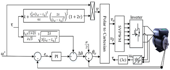
Figure 1.
Schematic representation of the direct voltage control.
It is evident from (6) and (7) and Figure 1 that the designed control method highly depends on the accuracy of the machine’s electrical parameters , , and , as well as the shaft speed and position. However, computing the MTPA in such a way and assuming the machine parameters are unchangeable throughout the entire operating range of the motor makes the proposed strategy invalid when the parameters of the motor are subjected to change due to magnet saturation, cross-coupling, temperature, etc. As a result of this variation, the actual MTPA trajectory deviates from the optimal one, causing high current consumption and hence affecting the performance of the entire control system. Furthermore, integrating mechanical sensors to acquire motor shaft speed and position information is subject to several limitations, including high costs, decreased reliability, poor noise immunity, and increased mounting space. Therefore, precise parameters and accurate information regarding rotor speed and position are critical for direct voltage control techniques to track the MTP trajectory precisely.
4. Proposed Sensorless Adaptive Direct Voltage MTPA with Multiparameter Estimation
To reduce the system’s cost and complexity, suppress the effect of parameter mismatches, and achieve high-performance direct voltage MTPA control, a sensorless adaptive direct voltage maximum torque per ampere (SADVC) scheme was developed. In this scheme, a fuzzy logic control-based cascaded model reference adaptive system (FLC-MRAS) was designed for speed and multiparameter estimation. In the cascaded scheme, two FLC-MRAS observers operate in parallel. The first is used to estimate rotor speed and position, while the other is a multiparameter observer utilized for permanent magnet flux and quadratic inductance identification. The identified parameters are used to update the speed estimator for precise position and speed estimation and, eventually, in the control system to guarantee accurate MTPA trajectory tracking. The proposed scheme is illustrated in Figure 2. Due to its ability to handle highly nonlinear systems and independence in precise mathematical modeling [38], a fuzzy logic controller (FLC) was used to replace the PI controller in the adaptive mechanism to enhance system robustness against sudden variations in speed and load torque and to eliminate the limitations of conventional PI controllers. As has been demonstrated in [39,40], the variation in is due to the saturation being much smaller than in and the flux linkage (), which has the dominant effect. Therefore, is considered constant for the whole process to avoid the rank-deficient problem for the multiparameter observer.
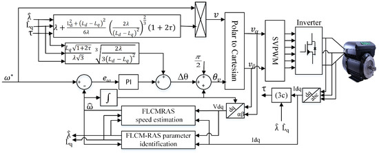
Figure 2.
Structure of the proposed adaptive direct voltage control.
5. Speed and Multiparameter Estimation Based on Cascaded MRAS
5.1. Principle of Conventional MRAS for Speed Estimation
The model reference adaptive system (MRAS) is a model-dependent algorithm. It mainly consists of two models: the reference model (actual motor) and the adjustable model, in addition to the adaptive mechanism. The reference model is used to determine the desired states, while the adaptive model is used to determine the estimated states. The output of the reference and the adjustable models are the actual (,) and estimated currents (, ). The difference between the output of the two models produces an error signal, which is applied to a PI-based adaptation mechanism [41]. The role of the adaptive mechanism is to estimate the rotor speed () and continuously update the adjustable model [35]. The rotor position can then be calculated by integrating the speed. The configuration of conventional MRAS is illustrated in Figure 3.
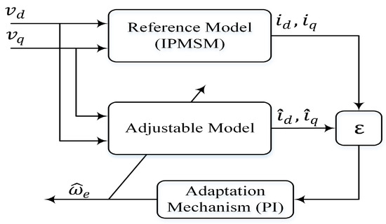
Figure 3.
Block diagram of conventional MRAS for speed estimation.
According to (1) and (2) and considering the d–q axis currents as state variables, the state-space representation of the reference model of the IPMSM is described as follows:
We define
Therefore, the state representation of the reference model can be simplified as
The state-space representation of the adjustable model of the IPMSM can be written in terms of estimated values as follows [42]:
where , and denote the estimated values of the electrical rotor speed and the -axis currents.
After developing the adaptive and reference models, an adaptation mechanism was constructed in such a fashion as to produce the estimated speed value and derive the error between the reference and the estimated d–q axis stator currents at its minimum value [43].
The error between the estimated and reference values of the d–q axis can be defined as
Therefore, the state error equation can be expressed as follows:
Equation (13) can be written as follows:
where A is the state matrix, is the state error vector, and W is the output vector of the feedback loop.
To ensure system hyperstability, two conditions must be fulfilled [44]. The matrix of the forward path must be strictly positive and real:
The nonlinear feedback must follow Popov’s criterion for stability,
where is a finite positive real number, and .
Lastly, the estimated speed from the MRAS can be achieved based on the proportional integral adaptation law, as follows:
We define
Therefore, Equation (17) can be written as
where and are the PI controller gains and is the initial estimated rotor speed.
5.2. Modified Conventional MRAS for Speed and Multiparameter Estimation
From (6), (7), and (10), it can be inferred that both the DVC and the previously developed conventional MRAS for speed estimation are highly dependent on machine parameters. However, these parameters are subject to changes during motor operations [8]. Compared to other parameters, variations in the permanent magnet flux () and quadratic inductance () significantly affect both the MTPA operating points and the estimation of the rotor speed and position [39]. Therefore, a PI-based cascaded MRAS (PI-MRAS) for speed and multiparameter estimation is constructed to estimate motor speed and and and update them simultaneously in the control system and speed estimator. The configuration of the PI-based cascaded MRAS is depicted in Figure 4.
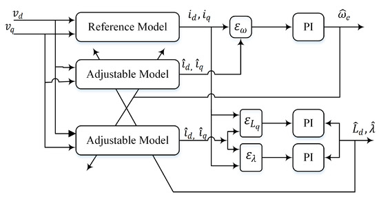
Figure 4.
Block diagram of PI-based cascaded MRAS.
With the same reference model described in (8), the adjustable model of the IPMSM for parameter estimation is described as follows [45]:
The state error equation is expressed as follows:
Based on Popov’s theory of hyperstability, the nonlinear feedback loop must satisfy the following formula [41]:
The adaptive law for and can be expressed as follows:
We define
Thus, Equations (27) and (28) can be written as follows:
5.3. Application of Fuzzy Logic Control for Speed and Multiparameter Estimation
Conventional MRAS schemes commonly use PI controllers in their adaption mechanism to estimate the desired variable in a way that minimizes the error between the two models. However, PI controllers necessitate a precise mathematical model and continual gain adjustment. Furthermore, their sensitivity to working conditions changes. Contributing to its ability to handle highly nonlinear systems [46], and independence in precise mathematical modeling, a fuzzy logic control-based cascaded MRAS (FLC-MRAS) is designed. In this scheme, a Mamdani-type fuzzy logic controller with dual input and single output is designed to replace all the PI regulators that were used in the cascaded PI-MRAS, ensuring high dynamic performance and less sensitivity to changes in working conditions. The configuration of the FLC-based cascaded MRAS is depicted in Figure 5. The errors () and their changes () are used as input, while the output is the rate of change of the estimated variables (), which passes through a discrete integrator to generate the estimated value of . The FLC inputs and output can be defined as follows:
where k and are indices denoting each variable’s current and past sample.
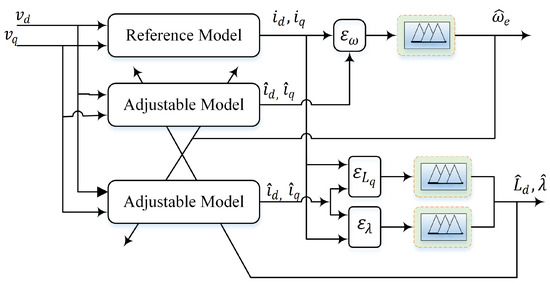
Figure 5.
Schematic representation of the proposed FLC-based cascaded MRAS.
The two inputs and the single output of each controller were normalized by scaling factors , , and , respectively. These factors constrain the variables to the desired limit, and their value selection is dominant in the system’s performance and stability. As usual, the scaling elements were tuned using trial and error techniques. For clarity, a detailed diagram of the FLC for speed estimation is shown in Figure 6.
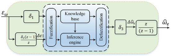
Figure 6.
Block diagram of the fuzzy logic controller for speed estimation.
Each controller’s crisp inputs and output values were translated to fuzzy values through a set of membership functions, as shown in Figure 7. Apart from the two fuzzy sets at the extreme ends, which were trapezoidal, 50% overlapped symmetrical triangular membership functions with a universe of discourse between [,1] were chosen to represent the three variables. The linguistic representation of these fuzzy sets is NB = negative big, NM = negative medium, NS = negative small, ZE = zero, PS = positive small, PM = positive medium, and PB = positive big. The matrix of fuzzy rules is depicted in Table 1. Of all the commonly utilized defuzzification algorithms, the center of gravity was used to calculate the crisp value of the estimated variables.
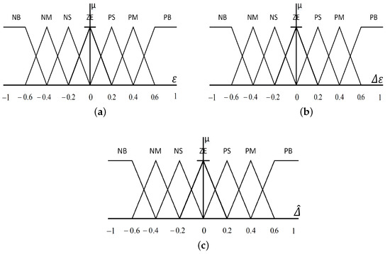
Figure 7.
Membership functions of fuzzy logic controller input and output. (a) Membership functions of errors (). (b) Changes in error membership functions (). (c) Membership functions of rate of change of the estimated variables ().

Table 1.
Linguistic fuzzy rules.
6. Results and Discussion
In order to examine the effectiveness of the introduced parameter-estimation-based sensorless adaptive direct voltage maximum torque per ampere control strategy, various simulation studies were carried out using MATLAB/Simulink. A 3.7 kW IPMSM with the parameters listed in Table 2 was implemented in this study. Since this work aims to introduce two new techniques, namely fuzzy logic control-based cascaded MRAS (FLC-MRAS) and sensorless adaptive direct voltage MTPA control (SADVC), various scenarios were adopted and extensively investigated.
Table 2.
IPMSM’s rated parameters.
The first scenario mainly investigated the effectiveness of the proposed FLC-MRAS, where the obtained results were compared with the conventional PI-based cascaded MRAS (PI-MRAS). Thus, the proposed and conventional MRAS were implemented to estimate the machine’s speed and nominal parameters under different speed and load conditions. The results are depicted in Figure 8 and Figure 9.
6.1. Performance under Speed Variation
In this test, the commanded speed was set to start from zero and then stepped up to 1500 rpm at t = 5 s; it then suddenly increased to its rated value of 1800 rpm at t = 30 s until t = 50 s, when the speed was brought back to 1500 rpm. At steady state, 10 N.m of load torque was introduced to the machine at t = 15 s and released at t = 60 s. The commanded, measured, and estimated speeds of the proposed FLC-MRAS and conventional PI-MRAS are presented in Figure 8a. As shown, both the estimated speed signals of FLC-MRAS and PI-MRAS overlap the measured speed and steadily converge to the reference speed. Compared to the PI-MRAS, the designed FLC-MRAS shows excellent performance with less estimation error and quick convergence when the speed is stepped up and down. Figure 8b shows the measured and estimated rotor position of the FLC-MRAS during the start-up period. The obtained results demonstrate that excellent tracking accuracy is achieved.
Figure 8c,d shows the actual and estimated permanent magnet flux and quadratic inductance, respectively. It can be observed that the designed FLC-MRAS exhibits better tracking accuracy with fast settlement and negligible oscillation during transient and speed changes. In flux estimation, the increase and decrease in the oscillation recovery times of the FLC-MRAS during transient and speed changes are 0.97 s, 1.152 s, and 0.935 s, respectively, while these values for the PI-MRAS are 1.514 s, 1.784 s, and 1.716 s. Additionally, the trends seen in inductance estimation with the FLC-MRAS were better than the PI-MRAS. Lastly, the estimation errors of the speed, permanent magnet flux, and quadratic inductance are depicted in Figure 9. The figures show that the proposed FLC-MRAS’s estimation accuracy is higher than that of the conventional PI-MRAS, especially during transient and speed step changes. During the start-up period and speed changes, the maximum absolute estimation errors of the FLC-MRAS for the speed, permanent magnetic flux, and quadratic inductance are 0.077 rpm, 1.967 Wb, and 4.332 H, respectively, which are very small quantities compared with the 0.0976 rpm, 4.515 Wb, and 1.32 H attained by PI-MRAS.
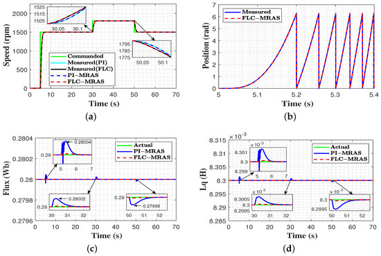
Figure 8.
Evaluation results under changes in speed. (a) commanded, measured, and estimated speed; (b) measured and estimated rotor position at start-up; (c) actual and estimated flux; and (d) actual and estimated quadratic inductance.
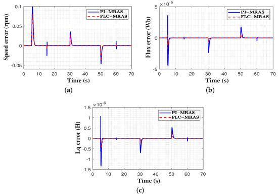
Figure 9.
Estimation error comparison under variable speed. (a) speed estimation error; (b) flux estimation error; (c) inductance estimation error.
6.2. Performance under Load Variations
In this evaluation, the speed was set to start from zero and then stepped up to its rated value of 1800 rpm at t = 5 s; this same speed was then maintained until t = 70 s. At steady state, 10 N.m of load torque was suddenly applied to the machine at t = 15 s until t = 35 s, when the load was increased to reach 15 N.m and then released at t = 60 s. The system’s performance is illustrated in Figure 10 and Figure 11. Figure 10a shows the signals for the commanded, measured, and estimated speeds of FLC-MRAS and PI-MRAS. As can be seen, both the estimated speed signals precisely track the measured rotor speed. The introduction of a sudden load torque and the torque’s release result in a remarkable momentary speed oscillation. In PI-MRAS, it is observed that at the beginning of the loading period, a speed drop of 10 rpm occurs at t = 15 s, and the speed recovers at t = 15.8 s, while in FLC-MRAS, a slight speed drop of 2 rpm is observed and immediately compensated for at t = 15.4 s. This denotes that the settling time of the designed FLC-MRAS control is remarkably less than for PI-MRAS. In the unloading period, PI-MRAS shows a speed overshoot of 11 rpm at t = 60 s, and it recovers at t = 61.25 s. In contrast, the FLC-MRAS exhibits only an overshoot of 2 rpm, and it immediately recovers at t = 60.25 s. Thus, the designed MRAS’s ability to perform disturbance rejection is excellent. The measured and estimated electrical rotor position of the FLC-MRAS during start-up are illustrated in Figure 10b. As shown, the estimated position precisely tracks the measured value of the rotor position. Figure 10c,d shows the actual and the estimated permanent magnet flux and quadratic inductance of the PI and FLC MRAS under varying torque conditions. Compared to PI-MRAS, the FLC-MRAS control achieved high estimation accuracy. As revealed, both strategies exhibit oscillations during the loading and unloading period of the load torque. However, the oscillation seen with the FLC-MRAS control is negligible compared with the PI-MRAS. Furthermore, the convergence time of the FL-MRAS control is very short. Figure 11 presents the estimated errors of speed, permanent magnet flux, and quadratic inductance. In comparison to the PI-MRAS control method, which shows maximum absolute estimation errors of (0.143 rpm, 5.266 Wb, 1.975 H) for speed, permanent magnetic flux, and quadratic inductance, respectively, the proposed FLC-MRAS achieves a reduced estimation error of 0.114 rpm, 1.928 Wb, 6.325 H and quickly converges to zero for the three values.
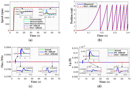
Figure 10.
Results of evaluation carried out with changes in load torque. (a) commanded, measured, and estimated speed; (b) measured and estimated rotor position at start-up; (c) actual and estimated flux; (d) actual and estimated quadratic inductance.
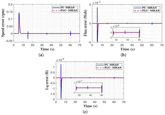
Figure 11.
Estimation error comparison under variable load. (a) speed estimation error; (b) flux estimation error; (c) inductance estimation error.
6.3. Performance under Parameter Variation
Direct voltage maximum torque per ampere control (DVC) is a parameter-dependent technique. However, these parameters are time-varying and may change due to many factors (saturation, temperature, working condition changes, etc.). Therefore, the second scenario investigates the effectiveness of the proposed SADVC against parameter variation. Two evaluations are carried out to express the performance of the designed scheme under variations in the permanent magnet flux and quadratic inductance. Lastly, a comparison against the DVC is conducted to highlight the merits of the proposed SADVC.
6.3.1. Performance under Permanent Magnet Flux Variation
In this test, the commanded speed started from zero, then stepped up to 1500 rpm at t = 5 s and continued until t = 70 s. A 10 N.m load torque was applied to the machine at t = 20 s and continued to t = 70 s. The permanent magnet flux started at its nominal value and suddenly increased by 20% at t = 40 s. These conditions were applied to the DVC without using any parameter estimation technique and the proposed SADVC. The achieved outcomes are depicted in Figure 12 and Figure 13. The commanded speed, measured and estimated speed of SADVC, and measured speed of DVC under flux variation are presented in Figure 12a. It is clear that when the permanent magnet flux is increased, the measured speed of DVC exhibits a speed deviation of 15 rpm and gradually recovers in 1.15 s. In comparison to the DVC, the estimated speed of the proposed SADVC overlaps the measured speed and smoothly converges to the reference in 0.25 s because the magnetic flux is identified online and updated in the control system. Figure 12b portrays the stator current magnitude based on both methods. As a result of flux increase, a high current consumption of about (15.7 A) is observed in the DVC due to the lack of online identification of flux increase, while in SADVC, the current magnitude is (6.7 A). This denotes that the proposed SADVC is constrained within the MTP operating points. Compared to the SADVC, the voltage amplitude and angle of DVC due to flux increase are entirely different from the optimal pairs that force the motor to work within the MTPA points, as seen in Figure 12c,d. Lastly, the estimation accuracy of the proposed FLC-MRAS during flux change is contrasted to the conventional PI-MRAS, and the results are displayed in Figure 13. From the results, it can be inferred that when the magnetic flux is stepped up, the PI-MRAS shows an oscillation around the actual value with a maximum undershoot of 0.306 Wb and adjustment time of 0.086 s, whereas the FLC-MRAS exhibits a slight oscillation with a maximum undershoot of 0.32 Wb and recovers within 0.03 s. Therefore, less oscillations and quick convergence are achieved on FLC-MRAS. Furthermore, the estimated and reference currents are a perfect match.
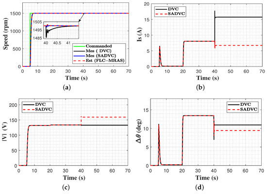
Figure 12.
Comparison between proposed SADVC and DVC under flux variation. (a) commanded, measured, and estimated speed; (b) stator current magnitude; (c) applied voltage magnitude; (d) applied voltage angle.
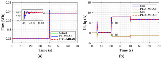
Figure 13.
Estimation accuracy under flux variation. (a) actual and estimated flux; (b) measured and estimated -axes currents.
6.3.2. Performance under Quadratic Inductance Variation
In this test, the reference speed was set to start from zero and then stepped up to reach 1500 rpm at t = 5 s; this continued until t = 70 s. A 10 N.m external load torque was applied to the machine at t = 20 s and continued until the end of the test. The quadratic inductance was initiated with its nominal value and suddenly reduced by 20% at t = 40 s. Both strategies were evaluated under the previously mentioned conditions, and the achieved results are illustrated in Figure 14 and Figure 15. Figure 14a shows the signals of the commanded, measured, and estimated speed of the SADVC and the measured speed of the DVC under inductance variation conditions. Compared to the measured speed of the designed SADVC, a speed oscillation with a maximum overshoot of 10 rpm at t = 40 s is observed in the measured speed of the DVC, which continues for 1 s. The estimated speed of the SADVC precisely tracks the measured speed, and both converge to the reference speed in 0.25 s with negligible oscillations. Figure 14b–d reveal that in DVC, the change in the quadratic inductance has a relatively small impact on the stator current, voltage amplitude, and angle but still maintains its effect on the accuracy of speed estimation. Figure 15 portrays the estimated quadratic inductance using PI-MRAs and FLC-MRAS. As can be seen, both strategies exhibit oscillations when the actual value of the inductance is stepped down. In comparison to the PI-MRAS, which shows a maximum overshoot of 0.0068 H and an adjustment time of 0.07 s, the FLC-MRAS shows only a maximum overshoot of 0.0064 H and a recovery time of 0.014 s. Consequently, the proposed FLC-MRAS offers better tracking accuracy in terms of oscillations and convergence time. Furthermore, the estimated currents precisely track the actual currents.
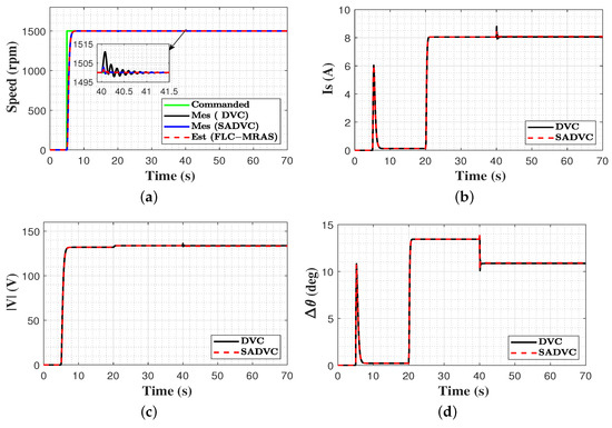
Figure 14.
Comparison between proposed SADVC and DVC under quadratic inductance variations. (a) commanded, measured and estimated speed; (b) stator current magnitude; (c) applied voltage magnitude; (d) applied voltage angle.
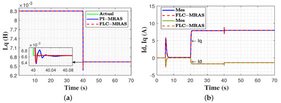
Figure 15.
Estimation accuracy under quadratic inductance variation. (a) actual and estimated inductance; (b) measured and estimated -axes currents.
6.4. Performance Evaluation under Low-Speed Profile
To further assess the performance of the suggested FLC-MRAS under a low-speed profile, an additional test was carried out. In this assessment, the reference speed was set to start from zero, then stepped up to reach 75 rpm (4% of the rated speed) at t = 5 s and continued until t = 70 s. A 5 N.m load torque was applied to the motor at t = 15 s and then released at t = 60 s. The evaluation outcomes are illustrated in Figure 16. Figure 16a shows the signals of the commanded, measured, and estimated speed of the FLC-MRAS. As can be seen, the estimated speed signal overlaps the measured signal and steadily converges to the commanded speed. At the beginning of the loading period, a slight speed drop of 0.6 rpm is observed and immediately compensated for in 0.55 s, while in the unloading period, a small overshoot of 0.5 rpm occurs and is recovered from in 0.52 s. This denotes that the designed strategy maintains its fast convergence even in low-speed operations. Figure 16b reveals that the estimated and the measured rotor positions are a perfect match. Figure 16c,d shows the actual and estimated permanent magnet flux and quadratic inductance under low-speed conditions. It can be inferred that the designed FLC-MRAS exhibits high tracking accuracy with a slight overshoot during the transient phase, which is recovered in 0.94 s. Lastly, the estimation error of the speed, permanent magnet flux, and quadratic inductance are shown in Figure 16e–g. The obtained results reveal that high estimation accuracy is achieved under low-speed operations, where the maximum absolute estimation error for the speed, permanent magnetic flux, and quadratic inductance are 1.5 rpm, 2.95 Wb, and 4 H, which are very small quantities.
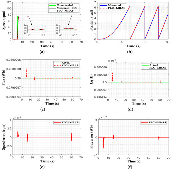
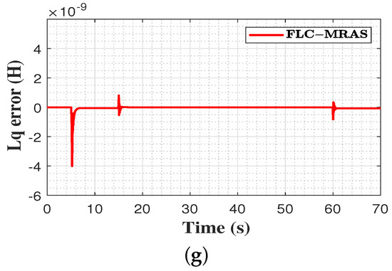
Figure 16.
Evaluation results under low speeds. (a) commanded, measured, and estimated speed; (b) measured and estimated rotor position at start-up; (c) actual and estimated flux; (d) actual and estimated quadratic inductance; (e) speed estimation error; (f) flux estimation error; (g) inductance estimation error.
6.5. Quantitative Assessment
To quantitatively assess the performance of the suggested FLC-MRAS, the accuracy with which this method tracked the estimated speed, permanent magnet flux, and quadratic inductance was considered in this task. The integral of absolute error () was used as a quantitative tracking metric and was calculated as
where and are the time intervals and e is the error between the actual and the estimated values. The results in (Section 6.2) were used for this evaluation. The evaluation results were compared with the conventional PI-MRAS, and the obtained numeric values are displayed in Table 3. As revealed, the proposed method shows better estimation accuracy with an improvement of 19%, 55.8%, and 44.55% for speed, permanent magnet flux, and quadratic inductance, respectively.
Table 3.
Performance evaluation.
7. Conclusions
This paper introduces a sensorless adaptive direct voltage maximum torque per ampere control strategy for interior permanent magnet synchronous machines (IPMSMs). To reduce the system’s cost, complexity, and the effect of parameter variation on both direct voltage MTPA and speed estimation at the same time, a cascaded MRAS for speed and multiparameter estimation is designed. In order to avoid the drawbacks of PI-based conventional MRAS, fuzzy logic controllers with two inputs and a single output are adopted to replace them. Extensive evaluation studies under different speed and load conditions are conducted to examine the effectiveness of the proposed scheme. Furthermore, the designed FLC-MRAS is tested under changes in the permanent magnet flux and inductance. A comparison against the conventional PI-MRAS is carried out. The obtained results reveal that the introduction of fuzzy logic controllers leads to better transient performance and quick convergence time, in addition to the ability to reject disturbances. Compared to the conventional PI-MRAS, the proposed FLC-MRAS shows fewer estimation errors for the three estimated variables. The online estimated values are applied to the control system, and high-efficiency sensorless adaptive direct voltage (SADVC) MTPA operation is achieved under various conditions. Thus, the effects of parameter variations are mitigated. Finally, a comparison against fixed-parameter-based DVC is carried out, and the results highlight the advantages of the proposed method. To further investigate the effectiveness of the proposed strategy on the basis of simulation studies or real-time implementations, future work will focus on high-power applications or experimental validation.
Author Contributions
Conceptualization, A.E. and H.C.; methodology, A.E., M.A. and H.C.; software, A.E. and M.A.; validation, A.E. and M.A.; formal analysis, A.E., M.A. and H.C.; investigation, A.E., M.A. and H.C.; resources, H.C.; data curation, A.E., M.A. and H.C.; writing—original draft preparation, A.E. and M.A.; writing—review and editing, A.E. and M.A.; visualization, A.E., M.A. and H.C.; supervision, H.C.; project administration, H.C. All authors have read and agreed to the published version of the manuscript.
Funding
This research received no external funding.
Data Availability Statement
Not applicable.
Conflicts of Interest
The authors declare no conflict of interest.
References
- Hang, J.; Wu, H.; Ding, S.; Hua, W.; Wang, Q. A DC-Flux-Injection Method for Fault Diagnosis of High-Resistance Connection in Direct-Torque-Controlled PMSM Drive System. IEEE Trans. Power Electron. 2020, 35, 3029–3042. [Google Scholar] [CrossRef]
- Anayi, F.J.; Al Ibraheemi, M.M. Estimation of Rotor Position for Permanent Magnet Synchronous Motor at Standstill Using Sensorless Voltage Control Scheme. IEEE/ASME Trans. Mechatron. 2020, 25, 1612–1621. [Google Scholar] [CrossRef]
- Hang, J.; Wu, H.; Ding, S.; Huang, Y.; Hua, W. Improved Loss Minimization Control for IPMSM Using Equivalent Conversion Method. IEEE Trans. Power Electron. 2020, 36, 1931–1940. [Google Scholar] [CrossRef]
- Nguyen, A.T.; Basit, B.A.; Choi, H.H.; Jung, J.W. Disturbance Attenuation for Surface-Mounted PMSM Drives Using Nonlinear Disturbance Observer-Based Sliding Mode Control. IEEE Access 2020, 8, 86345–86356. [Google Scholar] [CrossRef]
- Chen, Z.; Wang, F.; Luo, G.; Zhang, Z.; Kennel, R. Secondary Saliency Tracking-Based Sensorless Control for Concentrated Winding SPMSM. IEEE Trans. Ind. Inform. 2016, 12, 201–210. [Google Scholar] [CrossRef]
- Liu, X.; Chen, H.; Zhao, J.; Belahcen, A. Research on the Performances and Parameters of Interior PMSM Used for Electric Vehicles. IEEE Trans. Ind. Electron. 2016, 63, 3533–3545. [Google Scholar] [CrossRef]
- Li, K.; Wang, Y. Maximum Torque Per Ampere (MTPA) Control for IPMSM Drives Based on a Variable-Equivalent-Parameter MTPA Control Law. IEEE Trans. Power Electron. 2018, 34, 7092–7102. [Google Scholar] [CrossRef]
- Sun, T.; Wang, J.; Chen, X. Maximum Torque Per Ampere (MTPA) Control for Interior Permanent Magnet Synchronous Machine Drives Based on Virtual Signal Injection. IEEE Trans. Power Electron. 2015, 30, 5036–5045. [Google Scholar] [CrossRef]
- Azar, Z.; Zhu, Z.; Ombach, G. Influence of Electric Loading and Magnetic Saturation on Cogging Torque, Back-EMF and Torque Ripple of PM Machines. IEEE Trans. Magn. 2012, 48, 2650–2658. [Google Scholar] [CrossRef]
- Jeong, I.; Gu, B.G.; Kim, J.; Nam, K.; Kim, Y. Inductance Estimation of Electrically Excited Synchronous Motor via Polynomial Approximations by Least Square Method. IEEE Trans. Ind. Appl. 2015, 51, 1526–1537. [Google Scholar] [CrossRef]
- Shi, T.; Yan, Y.; Zhou, Z.; Xiao, M.; Xia, C. Linear Quadratic Regulator Control for PMSM Drive Systems Using Nonlinear Disturbance Observer. IEEE Trans. Power Electron. 2020, 35, 5093–5101. [Google Scholar] [CrossRef]
- Ge, H.; Miao, Y.; Bilgin, B.; Nahid-Mobarakeh, B.; Emadi, A. Speed Range Extended Maximum Torque Per Ampere Control for PM Drives Considering Inverter and Motor Nonlinearities. IEEE Trans. Power Electron. 2017, 32, 7151–7159. [Google Scholar] [CrossRef]
- Lai, C.; Feng, G.; Tjong, J.; Kar, N.C. Direct Calculation of Maximum-Torque-Per-Ampere Angle for Interior PMSM Control Using Measured Speed Harmonic. IEEE Trans. Power Electron. 2018, 33, 9744–9752. [Google Scholar] [CrossRef]
- Chen, Q.; Zhao, W.; Liu, G.; Lin, Z. Extension of Virtual-Signal-Injection-Based MTPA Control for Five-Phase IPMSM Into Fault-Tolerant Operation. IEEE Trans. Ind. Electron. 2019, 66, 944–955. [Google Scholar] [CrossRef]
- Li, L.; Liu, Q. Research on IPMSM Drive System Control Technology for Electric Vehicle Energy Consumption. IEEE Access 2019, 7, 186201–186210. [Google Scholar] [CrossRef]
- Chaoui, H.; Khayamy, M.; Okoye, O. MTPA based operation point speed tracking for PMSM drives without explicit current regulation. Electr. Power Syst. Res. 2017, 151, 125–135. [Google Scholar] [CrossRef]
- Chaoui, H.; Okoye, O.; Khayamy, M. Current Sensorless MTPA for IPMSM Drives. IEEE/ASME Trans. Mechatron. 2017, 22, 1585–1593. [Google Scholar] [CrossRef]
- Alzayed, M.; Chaoui, H. Efficient Simplified Current Sensorless Dynamic Direct Voltage MTPA of Interior PMSM for Electric Vehicles Operation. IEEE Trans. Veh. Technol. 2022, 71, 12701–12710. [Google Scholar] [CrossRef]
- Alzayed, M.; Chaoui, H. Energy Efficiency Improvement Using Simplified Dynamic Direct Voltage Maximum Torque Per Ampere Control for Interior PMSMs. IEEE/ASME Trans. Mechatron. 2023, 1–12. [Google Scholar] [CrossRef]
- Alzayed, M.; Chaoui, H.; Farajpour, Y. Dynamic Direct Voltage MTPA Current Sensorless Drives for Interior PMSM-Based Electric Vehicles. IEEE Trans. Veh. Technol. 2023, 72, 3175–3185. [Google Scholar] [CrossRef]
- Alzayed, M.; Chaoui, H. Direct Voltage MTPA Speed Control of IPMSM-Based Electric Vehicles. IEEE Access 2023, 11, 33858–33871. [Google Scholar] [CrossRef]
- Dianov, A.; Anuchin, A. Adaptive Maximum Torque Per Ampere Control of Sensorless Permanent Magnet Motor Drives. Energies 2020, 13, 5071. [Google Scholar] [CrossRef]
- Chen, Z.; Yan, Y.; Shi, T.; Gu, X.; Wang, Z.; Xia, C. An Accurate Virtual Signal Injection Control for IPMSM with Improved Torque Output and Widen Speed Region. IEEE Trans. Power Electron. 2021, 36, 1941–1953. [Google Scholar] [CrossRef]
- Wang, H.; Ge, X.; Liu, Y.C. Second-Order Sliding-Mode MRAS Observer-Based Sensorless Vector Control of Linear Induction Motor Drives for Medium-Low Speed Maglev Applications. IEEE Trans. Ind. Electron. 2018, 65, 9938–9952. [Google Scholar] [CrossRef]
- Bai, H.; Yu, B.; Gu, W. Research on Position Sensorless Control of RDT Motor Based on Improved SMO with Continuous Hyperbolic Tangent Function and Improved Feedforward PLL. J. Mar. Sci. Eng. 2023, 11, 642. [Google Scholar] [CrossRef]
- Li, Z.; Feng, G.; Lai, C.; Banerjee, D.; Li, W.; Kar, N.C. Current Injection-Based Multi-parameter Estimation for Dual Three-Phase IPMSM Considering VSI Nonlinearity. IEEE Trans. Transp. Electrif. 2019, 5, 405–415. [Google Scholar] [CrossRef]
- Yang, H.; Yang, R.; Hu, W.; Huang, Z. FPGA-Based Sensorless Speed Control of PMSM Using Enhanced Performance Controller Based on the Reduced-Order EKF. IEEE J. Emerg. Sel. Top. Power Electron. 2021, 9, 289–301. [Google Scholar] [CrossRef]
- Underwood, S.J.; Husain, I. Online Parameter Estimation and Adaptive Control of Permanent-Magnet Synchronous Machines. IEEE Trans. Ind. Electron. 2010, 57, 2435–2443. [Google Scholar] [CrossRef]
- Shi, Y.; Sun, K.; Huang, L.; Li, Y. Online Identification of Permanent Magnet Flux Based on Extended Kalman Filter for IPMSM Drive with Position Sensorless Control. IEEE Trans. Ind. Electron. 2012, 59, 4169–4178. [Google Scholar] [CrossRef]
- Liu, Z.H.; Nie, J.; Wei, H.L.; Chen, L.; Li, X.H.; Lv, M.Y. Switched PI Control Based MRAS for Sensorless Control of PMSM Drives Using Fuzzy-Logic-Controller. IEEE Open J. Power Electron. 2022, 3, 368–381. [Google Scholar] [CrossRef]
- Liu, Z.H.; Nie, J.; Wei, H.L.; Chen, L.; Li, X.H.; Zhang, H.Q. A Newly Designed VSC-Based Current Regulator for Sensorless Control of PMSM Considering VSI Nonlinearity. IEEE J. Emerg. Sel. Top. Power Electron. 2021, 9, 4420–4431. [Google Scholar] [CrossRef]
- An, X.; Liu, G.; Chen, Q.; Zhao, W.; Song, X. Adjustable Model Predictive Control for IPMSM Drives Based on Online Stator Inductance Identification. IEEE Trans. Ind. Electron. 2022, 69, 3368–3381. [Google Scholar] [CrossRef]
- Kivanc, O.C.; Ozturk, S.B. Sensorless PMSM Drive Based on Stator Feedforward Voltage Estimation Improved with MRAS Multiparameter Estimation. IEEE/ASME Trans. Mechatron. 2018, 23, 1326–1337. [Google Scholar] [CrossRef]
- Liu, Z.H.; Nie, J.; Wei, H.L.; Chen, L.; Wu, F.M.; Lv, M.Y. Second-Order ESO-Based Current Sensor Fault-Tolerant Strategy for Sensorless Control of PMSM with B-Phase Current. IEEE/ASME Trans. Mechatron. 2022, 27, 5427–5438. [Google Scholar] [CrossRef]
- Gadoue, S.M.; Giaouris, D.; Finch, J.W. MRAS Sensorless Vector Control of an Induction Motor Using New Sliding-Mode and Fuzzy-Logic Adaptation Mechanisms. IEEE Trans. Energy Convers. 2010, 25, 394–402. [Google Scholar] [CrossRef]
- Tahir, K.; Doumi, M.; Belfedal, C.; Allaoui, T.; Aissaoui, A.G.; Miloudi, A. A New Approach Fuzzy-MRAS Speed Sensorless Sliding mode Control for Interior Permanent-Magnet Machine Drive. J. Netw. Innov. Comput. (JNIC) 2014, 2, 158–165. [Google Scholar]
- Zerdali, E.; Barut, M. MRAS based real-time speed-sensorless control of induction motor with optimized fuzzy-PI controller. In Proceedings of the 2013 IEEE International Symposium on Sensorless Control for Electrical Drives and Predictive Control of Electrical Drives and Power Electronics (SLED/PRECEDE), Munich, Germany, 17–19 October 2013; pp. 1–5. [Google Scholar]
- M’hamed, L.; Roufaida, A.; Nawa, A.A.M.; Ameur Mezyane Nawal, A. Sensorless control of PMSM with fuzzy model reference adaptive system. Int. J. Power Electron. Drive Syst. (IJPEDS) 2019, 10, 1772–1780. [Google Scholar] [CrossRef]
- Liu, Q.; Hameyer, K. High-Performance Adaptive Torque Control for an IPMSM with Real-Time MTPA Operation. IEEE Trans. Energy Convers. 2017, 32, 571–581. [Google Scholar] [CrossRef]
- Wang, A.; Zhang, L.; Dong, S. Dynamic performance improvement based on a new parameter estimation method for IPMSM used for HEVs. In Proceedings of the IECON 2011-37th Annual Conference of the IEEE Industrial Electronics Society, Melbourne, Australia, 7–10 November 2011; pp. 1825–1829. [Google Scholar]
- Usama, M.; Kim, J. Improved Self-Sensing Speed Control of IPMSM Drive Based on Cascaded Nonlinear Control. Energies 2021, 14, 2205. [Google Scholar] [CrossRef]
- Bariša, T.; Erceg, I.; Marković, I. Estimation of stator resistance and rotor speed for IPMSG using model reference adaptive system. In Proceedings of the 2016 IEEE International Energy Conference (ENERGYCON), Leuven, Belgium, 4–8 April 2016; pp. 1–7. [Google Scholar]
- Khlaief, A.; Boussak, M.; Chaari, A. A MRAS-based stator resistance and speed estimation for sensorless vector controlled IPMSM drive. Electr. Power Syst. Res. 2014, 108, 1–15. [Google Scholar] [CrossRef]
- Sun, X.; Zhang, Y.; Tian, X.; Cao, J.; Zhu, J. Speed Sensorless Control for IPMSMs Using a Modified MRAS with Gray Wolf Optimization Algorithm. IEEE Trans. Transp. Electrif. 2022, 8, 1326–1337. [Google Scholar] [CrossRef]
- Jin, N.; Li, G.; Zhou, K.; Liu, J.; Iu, H.H.C. MTPA Trajectory Tracking Control with On-line MRAS Parameter Identification for an IPMSM. J. Electr. Eng. Technol. 2019, 14, 2355–2366. [Google Scholar] [CrossRef]
- Qin, J.; Du, J.; Li, J. Adaptive Finite-Time Trajectory Tracking Event-Triggered Control Scheme for Underactuated Surface Vessels Subject to Input Saturation. IEEE Trans. Intell. Transp. Syst. 2023, 24, 8809–8819. [Google Scholar] [CrossRef]
Disclaimer/Publisher’s Note: The statements, opinions and data contained in all publications are solely those of the individual author(s) and contributor(s) and not of MDPI and/or the editor(s). MDPI and/or the editor(s) disclaim responsibility for any injury to people or property resulting from any ideas, methods, instructions or products referred to in the content. |
© 2023 by the authors. Licensee MDPI, Basel, Switzerland. This article is an open access article distributed under the terms and conditions of the Creative Commons Attribution (CC BY) license (https://creativecommons.org/licenses/by/4.0/).