Abstract
This experimental study aimed to validate the integration of a gravitational loop heat pipe (GLHP) with respect to a gas fireplace insert. The GLHP was utilized to enhance the efficiency of the fireplace by preheating the combustion air with waste heat from flue gases. The experiment involved monitoring key parameters such as vapor and condensate temperatures and absolute pressure within the LHP. The results demonstrated that a filling volume of 0.1 L of water in the LHP allowed for successful operation, while exceeding 0.2 L resulted in flooding and decreased system efficiency. Challenges related to vapor production and condensate return were identified, suggesting the need for further research and design improvements. The experimental verification confirmed the feasibility of implementing the gravitational LHP in a gas fireplace insert and emphasized the importance of optimizing vapor production and condensate return mechanisms. This study contributes to the advancement of thermal management strategies and provides valuable insights for enhancing the design and performance of such systems.
1. Introduction
Improvement of the energy efficiency of buildings is one of the primary focuses of today’s world around us. Emphasis must be placed on the development of high-quality building designs. Some of the important factors in building design include the large service life or the application of assembled systems with eco-friendly removal [].
Energy expenditure is one of the unavoidable costs of all buildings due to thermal comfort in a socially shared need. The operation of buildings consumes roughly 30% of primary energy worldwide; thus, measures to reduce consumption are required []. When less heat is acquired from burning fuel, a smaller share of pollutants is expelled into the atmosphere. Various countermeasures were taken in action such as implementing renewable resources or exploiting solar gains. As the prices of nonrenewable sources steadily rise, the EU aims to increase the construction to buildings with minimal heat loss.
Boilers are the most common source of thermal energy for family homes. Fuel is burned in boilers, and the heat-carrying medium is heated. The market provides a large selection of boilers, but the choice for specific buildings is limited depending on some factors such as the access to a stable electric grid, possibility of placing the boiler, the associated exhaust fumes from the used fuel, the type of heating system, and the hot water heating solution in the object [].
Another limiting factor is the power output of the boiler, which must be at least as large as the heat losses of the house. With the help of regulation, the output can vary in very wide intervals. With modern boilers, it is possible to change the heat output according to the immediate need in the range of 30–100%. The use of fireplaces is especially widespread in smaller buildings, where heat is directly radiated into the room. Traditional fireplaces with an open hearth achieve minimal efficiency and are a very inefficient source of heat. Therefore, new design elements were introduced that increased the efficiency of these heat sources, such as the air circulation chamber. Wood-burning stoves achieve efficiency in the range of 75% and higher, while higher efficiency is achieved with pellet-burning boilers [,].
In boilers equipped with mechanical regulation of combustion air, the natural draft of the chimney is utilized to ensure air supply without the need for a fan. The power generated by these boilers is dependent on the opening position of the primary and secondary air supply, which is controlled by a thermoregulating valve. This valve senses the temperature of the heat-carrying medium and adjusts the position of the control flap to regulate the supply of combustion air using mechanical transmission. The control flap can be found either on the ashtray door or in the flue pipe. On the other hand, boilers featuring thermal output regulation are equipped with either a draft or an overpressure fan, which supplies the required amount of combustion air on the basis of the desired thermal output. The regulation can be achieved through fan speed setting or a control flap that governs the supply of combustion air. The thermal output regulation of these boilers is derived from the temperature of the heat-carrying medium, and the amount of combustion air is adjusted according to the difference between the desired and actual medium temperature. For boilers with manual operation, the control range typically varies from approximately 50% to 100% [].
Boilers equipped with heat output and combustion process regulation utilize either a draft or an overpressure fan, which can be controlled through speed adjustments or a control flap to regulate the amount of combustion air. This type of boiler offers the capability to adjust both power output and combustion quality. In its simplest form, the regulation of the boiler relies on the flue gas temperature, determining the appropriate adjustment or redistribution of the primary and secondary air supply to achieve the desired method of fuel combustion [].
Another parameter affecting the efficiency of boilers burning solid fuel is ash formation and deposition. During combustion, melting of ash can occur at relatively low temperatures, with further deposition or sticking of this melt on the heat exchange surfaces of the combustion device. The reason for ash sintering is the low characteristic melting point of ash of phytomass fuels. The problem with vegetable ash is free oxides and chlorides, which significantly reduce the value of the melting temperature of the ash. When removing these deposits, the boiler may be damaged [].
Boilers or fireplaces equipped with automatic gas burners are used to burn gaseous fuels. Their operation can be controlled automatically according to the planned daily regime. Boilers must be equipped with a safety device that protects them in the event of overheating, eliminates the possibility of gas poisoning, and enables safe ignition of the burners. The basic design element of boilers is a cast-iron or steel body with high-quality thermal insulation, which is equipped with a burner set with flame protection, ignition, and control, safety, and regulation equipment [].
Total efficiency of gas boilers and fireplaces ranges from 70% to 95% []. A further increase in efficiency is possible, for example, by using waste heat generated during combustion in a small heat source. For more efficient use of thermal energy or of waste heat, exchangers are proposed, which are mounted on the outer or inner surface of flues. Excess heat is removed by convection using flue gases, or it is radiated to the surroundings through the walls of the combustion chambers. This waste contains sufficient energy potential for the use of, e.g., heating, preheating of water, combustion air, or recovery systems [].
Unconventional methods of heating water include devices that use waste thermal energy or work with high heat transfer efficiency, such as heat pipes. These unconventional ways of heating hot water use different types and designs of exchangers in different conditions. The heat pipe is capable of highly efficient heat transfer, even over longer distances. It achieves significantly higher efficiency than currently available technologies. The advantage of heat pipes is the absence of dynamic parts such as pumps. The disadvantage is the high requirements for tightness and the material used for the given application. In this way, however, more thermal energy can be extracted, which lowers the temperature of the flue gases [].
Devices that increase the efficiency of the existing heat source in a family home will enable a reduction in primary energy consumption and financial savings. Increasing efficiency should be the main way to reduce the energy demand of buildings [].
During the design of the device, requirements were set for the removal of heat from the flue gas produced during the process of burning fuel in the heat source. From the point of view of the construction and arrangement of the individual parts of the device, it is necessary to ensure the location of the evaporative part of the heat pipe in the heat source so that the flue gases encounter the surface of the evaporative part.
The main goal of this study is to design and build a device for preheating combustion air with waste heat from flue gases, which will be based on the principle of heat transfer through a phase change. The device is a heat pipe that transfers heat under optimal conditions. In this experimental device, a closed-loop heat pipe is used, which forms a closed circuit during heat transfer through the working substance.
2. Device for Small Heat Source Efficiency Improvement
The proposed device (Figure 1) aims to enhance the efficiency of small heat sources by utilizing waste heat from flue gases to preheat the combustion air. It should be noted that no previous implementations have been carried out, and this current proposal represents the first of its kind. The device employs a loop heat pipe (LHP) system to transfer the heat effectively. By capturing the waste heat from the flue gases with an evaporator placed at the entry of chimney and utilizing it to preheat the incoming combustion air with a condenser placed in the combustion air supply channel, the device offers a novel solution to optimize the energy utilization of small-scale heat sources. This approach not only reduces energy waste but also enhances overall thermal efficiency, resulting in improved performance and reduced environmental impact. The utilization of LHP technology enables efficient heat transfer, making the proposed device a promising solution for enhancing the efficiency of small heat sources and maximizing energy utilization.
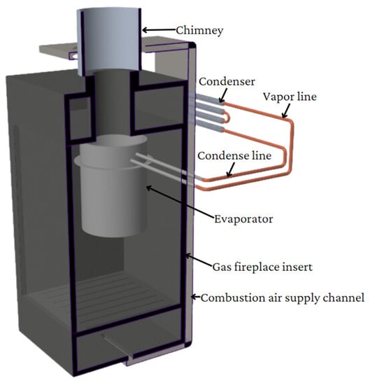
Figure 1.
Design of a device for increasing the efficiency of a small heat source.
2.1. Container Materials
LHPs have gained significant attention in thermal management systems due to their efficient heat transfer capabilities and versatility. One crucial component of an LHP is its container, which plays a vital role in ensuring reliable operation and optimal thermal performance []. Due to high temperatures that can be reached by flue gases, the evaporator is made from stainless steel, while the condenser consists of copper with aluminum rolled ribs to increase the heat exchanger surface area.
The choice of stainless steel as the material for the evaporator is driven by its excellent corrosion resistance properties and durability. Stainless steel is known for its resistance to oxidation and corrosion, making it suitable for applications where the working fluid or operating conditions are corrosive. Additionally, stainless steel offers sufficient mechanical strength to withstand the pressure differentials and thermal stresses experienced during LHP operation. The evaporator’s location before the chimney, where high temperatures are encountered, highlights the need for a robust material such as stainless steel to ensure reliable operation and prevent thermal degradation.
One relevant study investigated the startup characteristics of loop heat pipes with a stainless-steel container []. The research provided insights into the performance and behavior of LHPs using stainless-steel containers, enhancing our understanding of their suitability for high-temperature applications.
For the condenser section of the LHP, copper is chosen as the container material due to its exceptional thermal conductivity, which facilitates efficient heat transfer from the working fluid to the ambient environment. Copper containers can effectively dissipate heat, making them ideal for applications where heat rejection is critical. Additionally, copper exhibits good mechanical strength, ensuring the structural integrity of the condenser under operating conditions [].
To enhance the heat exchange surface area and improve heat transfer efficiency, aluminum rolled ribs are incorporated into the copper condenser. The ribs increase the heat transfer coefficient by promoting turbulent flow and disrupting the boundary layer, resulting in improved thermal performance. This design choice enables effective heat dissipation, contributing to the overall thermal efficiency of the LHP system [].
Research on the optimization of loop heat pipes has explored the structure of aluminum loop heat pipes with capillary wicks, shedding light on design considerations for the condenser section []. Although this study did not specifically focus on copper containers with aluminum rolled ribs, it provided valuable insights into the optimization of LHP designs and highlighted the significance of effective heat exchange surfaces.
In conclusion, the selection of container materials in loop heat pipes is crucial for ensuring reliable and efficient operation. In the case study discussed, stainless steel is chosen for the evaporator due to its corrosion resistance and durability, while copper with aluminum rolled ribs is utilized for the condenser to enhance heat transfer efficiency. These material choices, combined with the specific design considerations for high-temperature environments, contribute to the successful performance of the LHP system.
2.2. Working Medium
The choice of working medium in an LHP is critical as it directly impacts the system’s thermal performance and operational range. Several working fluids have been investigated and utilized in LHPs, including water, ammonia, acetone, and alkali metals. The selection depends on factors such as thermal properties, operating temperature range, compatibility with the container material, and specific application requirements [].
Water is a commonly used working medium in LHPs due to its favorable thermal properties, abundance, and non-toxic nature. When considering the compatibility of water with container materials, two important factors to consider are corrosion and thermal expansion [].
Stainless steel exhibits excellent corrosion resistance, making it compatible with water as a working medium in LHPs. The inert nature of stainless steel prevents the formation of corrosive reactions between the container material and water, ensuring long-term performance and reliability of the LHP system []. This corrosion resistance is particularly advantageous when LHPs are exposed to water with dissolved impurities or operating conditions that may promote corrosion.
Copper, known for its excellent thermal conductivity, is also compatible with water as a working medium in LHPs. While copper is generally resistant to corrosion from pure water, it may undergo corrosion in the presence of impurities or contaminants, such as dissolved oxygen or certain ions. However, the compatibility of copper with water can be improved by implementing appropriate water treatment techniques or utilizing deionized or distilled water in the LHP system [].
Considering the specific requirements of the LHP application where the device is placed in small heat sources and the working medium should not be explosive or flammable, water proves to be a suitable choice. Water is non-explosive and non-flammable, ensuring the safety of the LHP system in such environments.
In conclusion, water as a working medium is compatible with both stainless-steel and copper container materials in loop heat pipes. Stainless steel exhibits excellent corrosion resistance, while copper may require additional precautions to prevent corrosion. If the water used in the LHP system is of sufficient quality and free from impurities, both stainless-steel and copper containers can provide reliable performance and efficient heat transfer [,].
2.3. Design of the Proposed Device
The proposed device is a gravitational loop heat pipe (GLHP) designed for efficient heat transfer in a small heat source (Figure 2). The device utilizes the concept of an LHP, where the working fluid circulates through an evaporator and a condenser, driven by gravity. The unique design of the GLHP allows it to harness the heat from flue gases in the chimney for preheating combustion air.
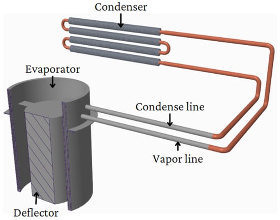
Figure 2.
Design of proposed device.
The evaporator of the GLHP is strategically positioned at the entry of the chimney where it is exposed to the heat generated by the flue gases. To ensure that the flue gases flow closer to the inner wall of the evaporator, a deflector is added coaxially, creating an inner ring for the flow of flue gases. This arrangement promotes efficient heat transfer from the flue gases to the working fluid within the GLHP.
In a GLHP, it is crucial to maintain a higher position for the evaporator compared to the condenser to facilitate the circulation of the working fluid. To achieve this, a combustion air supply channel is incorporated into the design. This channel provides the necessary height difference between the evaporator and the condenser, ensuring proper functioning of the GLHP. The size of the condenser is specifically designed to accommodate this arrangement.
The condenser of the GLHP consists of a copper pipe, which acts as a heat exchanger to transfer heat from the working fluid to the surrounding environment. To increase the heat exchange surface area and enhance the overall efficiency of the condenser, aluminum rolled ribs are added. These ribs provide additional surface area for heat transfer, allowing for improved thermal performance of the GLHP.
The design of this proposed device combines the principles of a gravitational loop heat pipe with specific features tailored to the small heat source. By utilizing the heat from flue gases and optimizing the positioning and design of the evaporator and condenser, the GLHP offers a promising solution for efficient heat transfer applications in chimneys. Further research and testing will be essential to validate and optimize the performance of this proposed design.
3. Mathematical Model
The development of mathematical models is essential for understanding and optimizing the performance of GLHPs. On the basis of large amount of available literature [,,], a mathematical model for a GLHP was developed to provide insights into its thermal behavior and performance. Equations (1)–(11) and (14)–(35) utilized for heat transfer calculations were sourced from [], and Equations (12) and (13) were sourced from []. The model considers the thermodynamic properties of the working fluid, heat transfer mechanisms, and the geometric configuration of the GLHP. By incorporating the governing equations of fluid flow, heat transfer, and energy balance, the model enables the prediction of key parameters such as temperature distribution, pressure drop, and heat transfer rates within the LHP.
3.1. Evaporator
The evaporator, a crucial component in the gravity loop heat pipe (GLHP) heat transfer process, plays a pivotal role in absorbing heat from the source and inducing the phase change of the working fluid. The heat transfer mechanisms within the evaporator are multifaceted.
Firstly, direct contact with the heat source occurs through a conductive interface, enabling the conduction of heat from the source to the evaporator wall. The resulting temperature gradient drives the heat transfer process. Secondly, the heat conducted through the evaporator wall is convectively transferred to the working fluid, and the design of the evaporator wall maximizes the contact area with the working fluid, optimizing heat transfer efficiency. As the working fluid absorbs heat, its temperature rises until it reaches the saturation temperature corresponding to the operating pressure of the evaporator. At this point, the liquid working fluid undergoes a phase change, vaporizing and transforming into steam, a process accompanied by the absorption of heat known as latent heat of vaporization. This phase change phenomenon facilitates efficient heat transfer, allowing significant amounts of heat to be transferred with relatively small temperature differences.
In summary, the heat transfer in a GLHP evaporator is a synergistic interplay of conduction, convection, and phase change mechanisms, enabling the efficient absorption of heat from the source and the conversion of the liquid working fluid into vapor, thereby facilitating efficient cooling and thermal management.
The flow of flue gases in the evaporator follows a specific path, initially along the outer wall and then along the inner wall. This longitudinal bypass of the evaporator facilitates heat transfer through convection between the flue gases and the inner and outer surfaces of the evaporator shell. The evaporator walls are characterized by their smooth and straight configuration, allowing for the consideration of heat transfer through a flat wall when analyzing the convective heat transfer on the outer shell. On the inner side of the evaporator, heat transfer in the annular region needs to be accounted for due to the presence of a deflector. Furthermore, the evaporator receives heat from the fireplace insert through radiation. Additionally, within the evaporator, the condensate undergoes boiling, which further contributes to the heat transfer process.
Flue gases heat the outer wall of the evaporator, flow through the inner ring, heat the inner wall, and continue to the chimney. The total heat transfer in this system is calculated using Equation (1).
where Qc is the total heat transfer by convection, and She is the surface area of the heat exchanger. Convection facilitates efficient heat transfer from the flue gases to the evaporator walls. The heat transfer rate q is calculated using Fourier’s law of thermal conduction (2).
The heat transfer coefficient ‘k’ is determined by the Equation (3), where λ represents thermal conductivity, and dss represents stainless-steel conductivity. This coefficient characterizes the efficiency of heat transfer and is crucial for analyzing thermal conductivity in a system.
The wall of the evaporator is exposed to flue gases, which in turn heat the wall. This transferred heat is then efficiently utilized to raise the temperature of the working medium (Figure 3). The process involves the conduction of heat through the wall, enabling the efficient exchange of thermal energy from the flue gases to the working medium, ultimately contributing to the overall performance and functionality of the system.
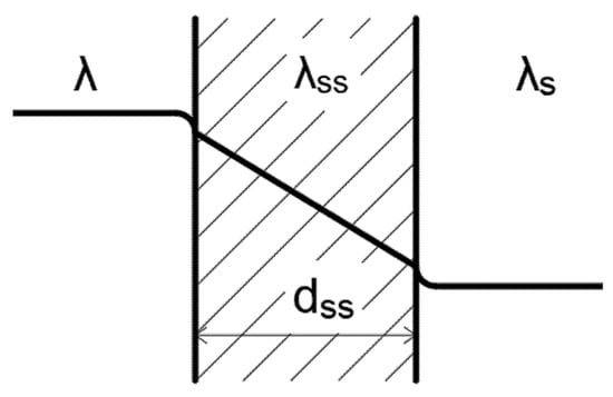
Figure 3.
Heat transfer through a plane wall.
The heat transfer coefficient ‘k’ can be calculated from the Nusselt number using Equation (4).
The calculation of thermal conductivity λ involves considering the thermokinetic temperature of the boundary layer Tδ (5). This temperature plays a significant role in determining the thermal conductivity value.
The average surface loss coefficient ε for a given length L can be determined using Equation (6), where ReL denotes the Reynolds number based on the length L. This coefficient characterizes the average surface losses within the flow and is derived from scientific principles. It provides valuable insights into the heat transfer behavior in the system.
The Reynolds number, denoted as ReL, is a dimensionless parameter used to characterize the flow regime. For laminar flow conditions (7), w represents the velocity of the fluid, L is the characteristic length, and v denotes the kinematic viscosity of the fluid. This criterion indicates that the flow is considered laminar when the Reynolds number falls below the specified threshold value of 3 × 10⁵.
The Prandtl number Pr is a dimensionless quantity that characterizes the relative importance of momentum and heat transfer in a fluid. It is defined as the ratio of kinematic viscosity ν to thermal diffusivity α (8).
For flow conditions where the Reynolds number ReL is less than 105 and the Prandtl number Pr falls within the range of 0.1 to 1000, the Nusselt number Nu can be determined using the correlation Equation (9).
This equation relates the Nusselt number to the Reynolds number and Prandtl number, capturing the combined effects of convective heat transfer and fluid properties. It provides an estimation of the convective heat transfer coefficient based on these dimensionless parameters.
The Nusselt number Nu for flow on the inner wall of the evaporator, with a Reynolds number Re below 2300, is determined by Equation (10). To ensure accurate application of this equation, it is important to have a Grashof number greater than 25,000 and a product of Re, Pr, and (D/L) equal to or greater than 7.17. The viscosity ratio (η/ηs) accounts for the ratio of fluid viscosities between the working fluid and the reference fluid.
Equation (11) provides valuable insights into the convective heat transfer behavior between a solid surface and a fluid medium. It considers factors such as the thermal conductivity λ, the Prandtl number Pr, and the flow characteristics including velocity w and characteristic length L. This equation allows for a better understanding of the average convective heat transfer coefficient α over a given length L.
The transfer of heat from the fireplace insert to the evaporator in a closed system involves radiation. The heat transfer is influenced by the surfaces of the evaporator A1 and the small heat source A2. The external radiation heat transfer, denoted as Qr,ext, is determined by the emissivity of the surfaces ε, which affects their ability to emit and absorb thermal radiation. The equation for Qr,ext is given by Equation (12), where the temperatures of the evaporator and the fireplace insert are denoted as T1 and T2, respectively, and Co is a constant.
The overall emissivity, ε12, is determined by the individual emissivities of the surfaces ε1 and ε2 and their respective areas A1 and A2. Radiant flux between surfaces A1 and A2 forming a closed system is shown on Figure 4.
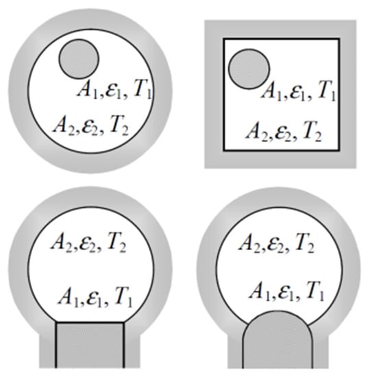
Figure 4.
Radiant flux between surfaces A1 and A2 forming a closed system [].
The relationship for ε12 (13) considers the interaction of the two surfaces in the radiation heat transfer process.
Heat transfer through boiling is a common phenomenon characterized by the formation and growth of vapor bubbles on a heated surface [,]. The heat transfer in this process is influenced by factors such as the Reynolds number ReB, Prandtl number Prk, and pressure p. In the case of bubble boiling, there are two criterial equations that describe the Nusselt number NuB for different ranges of Reynolds number. Equation (14) applies to ,while Equation (15) applies to .
These equations provide correlations between NuB, ReB, and Prk, allowing for the estimation of heat transfer performance in boiling systems within the specified range. It is important to note that the Prandtl number should be between 0.86 and 7.6, and the pressure should range from 4500 to 17.5 × 10⁶ Pa. These criterial equations serve as valuable tools in the design and optimization of heat transfer systems involving boiling, enhancing our understanding and control of heat transfer processes in such applications.
In boiling processes, the Nusselt number NuB is a key parameter that quantifies the convective heat transfer. It is defined by Equation (16), where h represents the convective heat transfer coefficient, B is a characteristic length, and λk is the thermal conductivity of the fluid.
The Reynolds number ReB characterizes the fluid flow behavior in boiling. It is determined using Equation (17), where q is the heat flux, B is a characteristic length, lb is the latent heat, ρs is the density of the fluid, and νc is the kinematic viscosity.
The Prandtl number Prk describes the relative importance of momentum diffusion to thermal diffusion in boiling. It is determined by Equation (18), where νc is the kinematic viscosity and αc is the thermal diffusivity of the fluid. The Prandtl number helps in understanding the relative rate of momentum and heat transfer during boiling.
The variable B in the equations represents a characteristic length scale, which is used to normalize the effects of size or geometry in the boiling process. It is defined by Equation (19), where cs is the specific heat capacity, ρc is the density of the solid, σ is the Stefan–Boltzmann constant, Ts is the surface temperature, lb is the latent heat, and ρc is the density of the fluid. The characteristic length B accounts for the specific thermodynamic properties of the system and enables a better understanding of the heat transfer phenomena during boiling processes.
The determination of the heat transfer coefficient in bubble boiling is influenced by the pressure conditions. For pressures up to p = 105 Pa, the heat transfer coefficient h can be calculated using Equations (20) and (21), where ∆T is the temperature difference and q is the heat flux.
For pressures ranging from 0.01 to 15 MPa, the heat transfer coefficient is given by Equations (22) and (23). These equations provide a means to estimate the heat transfer coefficient on the basis of the pressure and temperature difference, allowing for analysis and design of bubble boiling systems.
3.2. Condenser
Heat transfer in the GLHP condenser plays a vital role in efficient thermal management by facilitating the release of heat from steam to combustion air. This process involves several key mechanisms that contribute to heat transfer within the condenser.
Firstly, hot vapor from the evaporator enters the condenser and contacts the condenser wall, which is at a lower temperature. Heat is then conducted from the steam to the condenser wall. The temperature difference between the vapor and the condenser wall drives this heat transfer process.
Secondly, as the vapor encounters the cooler condenser wall, it undergoes a phase change from vapor to liquid through condensation. This phase change releases latent heat of condensation, which is the thermal energy associated with the transition. The condenser wall effectively absorbs this latent heat, contributing to the overall heat transfer process. The condensed liquid resulting from condensation flows down the condenser wall under the influence of gravity, returning to the evaporator section. This flow ensures a continuous supply of liquid working fluid to the evaporator, thereby sustaining the operation of the GLHP system.
Overall, heat transfer in the GLHP condenser involves conduction, condensation, and gravity-driven liquid flow mechanisms. These processes work in tandem to extract heat from the vapor and release it to the combustion air, enabling effective cooling and thermal regulation.
The condenser of the GLHP system is cooled by the supplied combustion air, with heat transfer occurring as the air flows transversely around the condenser. The condenser is typically constructed using a ribbed tube, comprising both a smooth section and ribs. Heat conduction takes place through the folded cylindrical wall of the condenser, allowing for efficient transfer of thermal energy. Functioning as a four-stroke heat exchanger with one-sided mixed flow, the condenser ensures effective heat transfer within the GLHP system.
The condenser comprises a linear array of four ribbed tubes, and the heat transfer efficiency and pressure drop in the tube bundle with external fins are influenced by a multitude of geometric parameters. To assess the hydraulic and thermal performance of the condenser, mathematical relationships that incorporate the geometric characteristics of the individual tubes and the tube bundle can be employed.
One such correlation is the Nusselt number in Equation (24). This equation encapsulates the heat transfer coefficient Nu, the mass velocity on the tube side Gα, the Reynolds number Re, and the Prandtl number Pr.
Furthermore, relation (25) provides insights into the heat transfer surface area (α × S) and the size of the tube bundle C. Here, S1, nr, l1, ϕ, Sr, St, and ηr represent geometric parameters associated with the arrangement of the tube bundle.
The coefficients Kα and n are determined on the basis of the specific geometric attributes of the tubes (Table 1). For the specific configuration of tubes arranged in a linear fashion, the value of Gα is unity. This simplification is applicable to the arrangement of the four ribbed tubes within the condenser. By considering these geometric parameters and employing the pertinent equations, the hydraulic and thermal characteristics of the condenser system can be effectively evaluated with enhanced precision.

Table 1.
Values of Kα and n depending on the Reynolds number.
In the context of fluid dynamics, the Reynolds number Re is determined at the narrowest section of the tube bundle. It is defined as the ratio of the velocity w to the kinematic viscosity v (26). Here, de represents the equivalent diameter of the ribbing, which is considered a characteristic dimension.
The hydraulic diameter dh is employed to estimate de and is calculated using relationship (27). In this expression, St denotes the total surface area, dt refers to the tube diameter, Sr represents the rib surface area, and nr corresponds to the number of ribs per tube.
The Nusselt number Nu characterizing the heat transfer in this situation can be expressed as (28), where C represents a constant, ρv is the density of the vapor, g denotes the acceleration due to gravity, ρp corresponds to the density of the fluid, hfg represents the average latent heat of vaporization, D represents the characteristic length or diameter, μv is the dynamic viscosity of the vapor, kv denotes the thermal conductivity of the vapor, Tsat is the saturation temperature, and Ts represents the surface temperature.
The addition of aluminum rolled ribs to a smooth copper tube enhances heat transfer by increasing the surface area available for heat exchange. This improvement is achieved through a combination of conduction and convection mechanisms.
Conduction enables efficient heat transfer from the inner surface of the copper tube to the outer surface, allowing heat to flow into the aluminum ribs. The high thermal conductivity of copper facilitates this process, promoting effective conduction across the interface.
Convective heat transfer occurs as fluid flows over the outer surface of the ribbed structure. The presence of the aluminum ribs disrupts the fluid flow, creating turbulent boundary layers that enhance convective heat transfer. This turbulent flow promotes efficient heat exchange between the fluid and the aluminum ribs.
The combination of conduction and convective heat transfer between the copper tube and the aluminum ribs results in improved heat transfer performance. By increasing the available surface area, the addition of aluminum rolled ribs enhances the overall efficiency of heat exchangers.
The cylindrical wall consists of two layers, and the equations describe the heat transfer across the wall. Equation (29) represents heat transfer from the inner surface to the outer surface, while (30) represents heat transfer from the outer surface to the surroundings. These equations determine temperature differences and heat flow rates.
To calculate the temperature difference across the entire wall, Equation (31) is used. This accounts for heat flow rates and thermal conductivities of both layers, providing insight into temperature distribution.
The equivalent thermal conductivity λₑₖᵥ of the composite wall is determined by (32). This equation provides the overall thermal conductivity of the composite wall, considering individual conductivities and geometries of the layers.
Equations (30)–(32) enable analysis of heat transfer in cylindrical walls with multiple layers, providing valuable insights into temperature distribution, heat flow rates, and effective thermal conductivity. The dimensions appearing in relations (30)–(32) are illustrated in Figure 5.
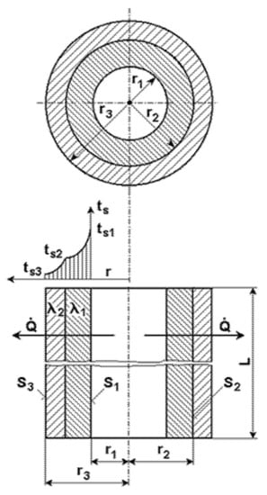
Figure 5.
Heat transfer through a compound cylindrical wall.
The heat transfer process in the condenser involves the direct flow of combustion air perpendicular to the axis of the finned tubes. This airflow configuration promotes efficient heat exchange by allowing the air to mix with the surrounding environment. However, the walls of the condenser tubes act as barriers, preventing the partial streams of steam from mutually mixing within the condenser.
As a result, the condenser operates as a four-stroke heat exchanger with a one-sided mixed crossflow. The combustion air flows across the condenser tubes, absorbing heat from the steam as it passes through the finned surfaces. This one-sided mixed crossflow design ensures effective heat transfer between the steam and the surrounding air, facilitating the release of thermal energy from the condenser.
In heat exchanger analysis, the logarithmic temperature difference method is employed to determine temperature distributions and temperature differences across the exchanger. The method utilizes the concept of a logarithmic temperature difference to obtain more accurate estimations of heat transfer performance.
The temperature at the first fluid outlet, ts1, can be calculated using Equation (33)
Similarly, the temperature at the second fluid outlet, ts2, can be determined by Equation (34).
The mean temperature difference, Δtm, can be determined by Equation (35).
In Equations (33)–(35), t1 and t2 represent the inlet temperatures of the first and second fluids, α1 and α2 are the heat transfer coefficients of the respective fluids, S1 and S2 are the heat transfer surface areas on the respective sides, D1 and D2 are the diameters of the channels, L is the length of the heat exchanger, and λekv represents the equivalent thermal conductivity of the composite wall.
The mean logarithmic slope method provides a more accurate evaluation of temperature differences and facilitates the analysis and design of heat exchangers. By considering the logarithmic average of temperature differences, it accounts for variations in temperature distribution across the exchanger, enabling improved heat transfer calculations.
3.3. Results
The heat output of the evaporator is influenced by the rising flue gas temperature (Figure 6). As the flue gas temperature increases, all heat outputs exhibit a diminishing trend. Amongst these outputs, the dominant contribution comes from the radiative heat transfer rate, Qr,int, which acts upon the inner wall of the evaporator. Remarkably, this radiative heat transfer rate surpasses the convective heat outputs, Qk,ext and Qk,int, on the outer and inner surfaces of the evaporator, respectively. Furthermore, the heat outputs on the inner surface of the evaporator demonstrate higher magnitudes compared to those observed on the outer shell of the evaporator.
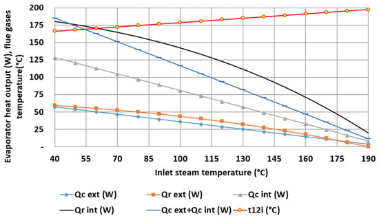
Figure 6.
Heat output by the evaporator and the temperature of the flue gases at the outlet of the evaporator depending on the boiling temperature.
The logarithmic temperature difference method (LDMT) was validated by comparing it with the operational characteristic function (char) to evaluate heat transfer in the condenser. Both methods yielded consistent results, indicating a reliable estimation of heat transfer (Figure 7).
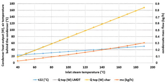
Figure 7.
Heat output by the condenser and at the outlet of the evaporator depending on condensation temperature.
With increasing steam temperature, the temperature of the combustion air t22 also rose. Consequently, the temperature difference between the combustion air and steam increased. This larger temperature difference enhanced the efficiency of heat transfer between the condenser and the combustion air, leading to improved heat exchange performance.
The mass flow rate of the working fluid varied with the change in flue gas temperature in both the evaporator and the condenser (Figure 8). By overlaying the curves of the condensate mass flow rate ṁc and the steam mass flow rate ṁs, a point was identified with equal temperature and pressure, where the amount of evaporated condensate was equal to the amount of condensed condensate. The cooperation between the evaporator and the condenser is contingent upon maintaining identical temperature and pressure in both devices. The collaboration of the evaporator and the condenser occurs at a steam temperature of 160 °C and a saturated steam pressure of 618.3 kPa.
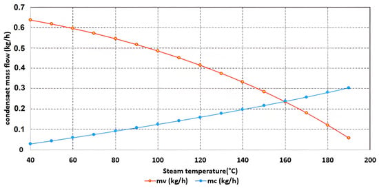
Figure 8.
Determining the cooperation parameters of the evaporator and the condenser.
On the basis of the initial parameters used in the device’s design, we determined the efficiency of the small heat source. Subsequently, the mathematical model provided insights into the cooperative behavior of the evaporator and the condenser, allowing us to evaluate the device’s influence on enhancing the efficiency of the small heat source.
The mathematical model facilitated a recalibration of the small heat source’s efficiency, incorporating the parameters obtained from the simulation results. The model’s predictions demonstrated that the proposed device led to a significant improvement in the efficiency of the small heat source. The efficiency gains achieved were notable, with an increase of up to 3%. This enhancement is of great significance for small-scale heat sources, as even slight improvements can result in significant energy savings and operational cost reductions.
Moreover, the mathematical model’s comprehensive overview provided valuable insights into the underlying heat transfer mechanisms and interactions within the device. This deeper understanding of the system’s behavior enables further optimizations and potential modifications to achieve even higher efficiency gains.
In conclusion, our mathematical model demonstrated the considerable impact of the proposed device on improving the efficiency of small heat sources. This study serves as a foundation for future research and development in the field of thermal management and energy efficiency, offering promising possibilities for sustainable heat utilization and economic benefits.
4. Experimental Verification
An experimental verification of the gravitational loop heat pipe (GLHP) was conducted to investigate its effectiveness in preheating combustion air using heat from flue gases, with the aim of increasing the efficiency of a gas fireplace insert. The experiment was carried out with an evaporator positioned at the entry to the chimney and a condenser in the combustion air supply channel.
The primary objective of the experiment was to assess the performance of the GLHP in utilizing waste heat from flue gases to preheat the incoming combustion air. By transferring heat from the flue gases to the combustion air, the GLHP aimed to enhance the overall efficiency of the gas fireplace insert.
The experiment involved the use of several sensors to measure and monitor important parameters. NiCr–Ni thermocouples were utilized to measure temperatures at various points within the system, including the evaporator, condenser, combustion air supply channel, and flue gases. These thermocouples provided accurate and reliable temperature measurements, enabling precise monitoring of heat transfer processes.
Thermocouples were subjected to calibration procedures utilizing the precision instrument known as the miniature hot point dry block calibrator, specifically the CL1000A model. The accuracy achieved in these calibrations is of the order of five-hundredths of a degree Celsius.
To measure the absolute pressure within the gravitational loop heat pipe (GLHP), an FD 8214 M12U sensor was employed. This sensor provided real-time pressure readings with accuracy of ±0.1%, allowing researchers to assess the pressure distribution and behavior within the GLHP during operation.
The velocity of the combustion air in the supply channel was measured using an FVAD 35 TH5K1 sensor. The velocity sensor FVAD 35 TH5K1 exhibits a high level of accuracy, with a precision of ±2% concerning the measured velocity. This sensor enabled the evaluation of the airflow velocity, which is crucial in determining the effectiveness of the GLHP in preheating the combustion air.
Additionally, a flue gas analyzer, specifically the testo 350 model, was utilized to analyze the composition and properties of the flue gases. This analyzer provided measurements of important parameters such as oxygen (O2) content, carbon dioxide (CO2) concentration, and carbon monoxide (CO) levels. These measurements helped assess the combustion efficiency and environmental impact of the gas fireplace insert.
By utilizing these advanced sensors, the experiment was able to capture and analyze crucial data, enabling a comprehensive evaluation of the performance and efficiency of the gravitational LHP in preheating combustion air.
Figure 9 illustrates the specific locations where critical measurements were taken to analyze the performance of the gravitational LHP system for preheating combustion air. Temperature sensors were strategically placed at key points to capture the thermal dynamics of the system. Pressure measurements were conducted to assess the absolute pressure within the system, providing valuable insights into the fluid behavior. Velocity measurements were taken to quantify the airflow characteristics in the combustion air supply channel. Volume flow measurements allowed for the assessment of the volumetric flow rate of the air and natural gas. Additionally, measurements of the coefficient of excess air in flue gases was performed. These comprehensive measurements at the designated locations provided a thorough understanding of the thermal and fluid dynamics within the GLHP system, enabling a comprehensive analysis of its performance.
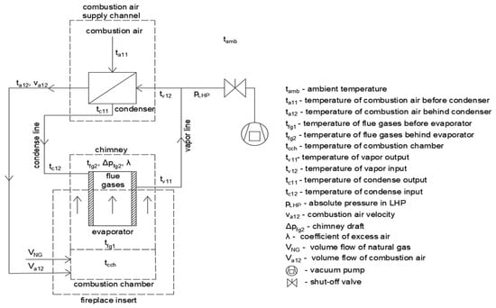
Figure 9.
Measurement scheme.
To evaluate the impact of the GLHP on the gas fireplace insert, various parameters were measured (Figure 10). These included temperature, pressure, flow rates, and thermal conductivity. The measurements were taken in both the empty LHP configuration and the LHP-integrated configuration to compare the effects of the LHP on the behavior of the fireplace insert. By analyzing these parameters, the performance enhancements and energy efficiency improvements resulting from the LHP integration were quantified.
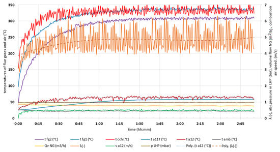
Figure 10.
Course of measured values on a fireplace insert without LHP filling (nomenclature in Figure 9).
The filling ratio, which represents the fraction of the internal evaporator volume occupied by the working fluid, significantly affects the performance of a LHP utilizing water as the working medium. Research studies have shown that the filling ratio has a substantial impact on the thermal performance and operational limits of the LHP. Higher filling ratios generally lead to improved heat transfer characteristics due to increased liquid inventory for phase change and thermal transport. This results in enhanced heat dissipation and higher thermal efficiency. However, excessively high filling ratios can result in elevated pressure drops, potential flooding issues, and operational constraints. Conversely, lower filling ratios may lead to reduced heat transfer capacity and overall thermal performance. Therefore, selecting an optimal filling ratio is crucial for achieving efficient and reliable operation of the LHP [].
In the experimental setup, 0.1 L of water was introduced into the GLHP installed in the gas fireplace insert. The purpose of this experiment was to investigate the behavior and limitations of the LHP when operating with a small water volume. It was observed that, when the filling exceeded 0.2 L, the LHP experienced flooding, indicating that the system reached its maximum capacity.
The LHP performance was assessed by monitoring key parameters, including the vapor temperature at the input and output, condensate temperature at the input and output, and absolute pressure within the LHP (Figure 11). Upon reaching a sufficient vapor quantity, the temperatures of the input and output vapor closely matched that of the condensate input. As the gas fireplace insert’s temperature stabilized, the temperature differential between the vapor input and output gradually increased. However, due to inadequate vapor production, condensate accumulation occurred in the condenser, impeding its return to the evaporator.
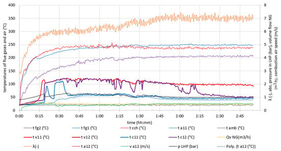
Figure 11.
Course of measured values on a fireplace insert with filling of 0.1 L of water in LHP (nomenclature in Figure 9).
These findings highlight an inherent imbalance in the LHP system, resulting in suboptimal condensate circulation. Consequently, further investigation and design adjustments are necessary to enhance vapor generation and facilitate efficient condensate return, thereby optimizing the system’s overall performance.
5. Discussion
In comparing the results of gravitational loop heat pipes (LHPs) used for waste heat recovery, several studies have shed light on the performance and efficiency of such systems. Li et al. conducted an experimental investigation on a gravitational LHP for waste heat recovery in data centers, highlighting its effectiveness in recovering waste heat and improving energy efficiency []. Similarly, Kim et al. examined the performance characteristics of a loop heat pipe for waste heat recovery applications, emphasizing its capability to enhance heat transfer and overall system efficiency []. Another study by Zhang and Liu explored the application of a loop heat pipe for waste heat recovery from exhaust gas in internal combustion engines, showcasing its potential in recovering and utilizing waste heat effectively []. These studies collectively highlight the significance of gravitational LHPs in waste heat recovery scenarios, emphasizing their role in improving energy efficiency and reducing energy wastage. The findings from these studies provide valuable insights and benchmarks for comparing the results of our experimental verification and further support the potential benefits of utilizing gravitational LHPs for waste heat recovery applications.
According to the mathematical modeling results, the implementation of a gravitational LHP in a small heat source shows a promising 3% increase in efficiency. The mathematical model predicts that the LHP effectively transfers heat from the flue gases to the combustion air, leading to enhanced thermal performance and improved energy utilization.
The utilization of a gravitational LHP offers the potential for waste heat recovery and preheating of the combustion air, which can significantly contribute to increasing the overall efficiency of small heat sources. The 3% efficiency gain, as predicted by the mathematical model, highlights the positive impact of integrating LHP technology into the system.
The comparison between the mathematical model and the experimental verification of the GLHP involved assessing the performance under different operating conditions. In the mathematical model, the GLHP operated with the working medium in a vapor state at a specified temperature of 160 °C and an absolute pressure of 618.3 kPa. In the experiment, the GLHP operated at around 120 °C and an absolute pressure of 120 kPa. Despite the variation in operating parameters, it is essential to acknowledge the practical constraints that influenced the experimental setup. While the model considered the placement of the GLHP at the entrance of the chimney, the actual implementation required adapting to the construction of the gas fireplace insert. Consequently, the evaporator was positioned in the combustion chamber and isolated to minimize direct heating from the flame. Understanding such practical adaptations is crucial for interpreting the comparison results, as it may account for some deviations between the model and the experiment. By incorporating these considerations into the analysis, a more comprehensive evaluation of the GLHP’s performance can be achieved, leading to improved model accuracy and real-world applicability.
In the experimental investigation conducted on a gas fireplace insert with a gravitational LHP, different water filling levels were examined. It was observed that a water filling over 0.2 L resulted in flooding within the system, leading to operational issues. To address this, a reduced water filling of 0.1 L was implemented.
The experimental investigation conducted on a gas fireplace insert equipped with a gravitational LHP revealed important observations. After reaching a sufficient vapor quantity, the temperatures of the vapor input and output closely matched the condensate input temperature. As the gas fireplace insert stabilized at its operational temperature, the temperature difference between the vapor input and output gradually increased. However, limited vapor production posed challenges in returning the accumulated condensate from the condenser back to the evaporator, impeding the desired flow of working fluid within the LHP system.
When gravitational LHPs encounter limitations in condensate flow due to a low height difference between the condenser and evaporator, alternative design changes become necessary to ensure their functionality, especially in scenarios where accommodating small heat sources restricts height adjustments. One potential solution is the incorporation of capillary wicks within the LHP design. Capillary wicks provide an additional driving force for condensate flow, mitigating the reliance on gravitational forces and overcoming the height limitation challenge.
Studies have investigated the effectiveness of capillary wicks in LHPs for heat transfer enhancement and condensate management. Xu et al. explored the utilization of a hybrid wick structure in a LHP for waste heat recovery, demonstrating improved heat transfer and efficient condensate return []. Similarly, Liu et al. investigated the performance of a LHP with a capillary structure for cooling electronic devices, achieving enhanced heat transfer and maintaining stable operation [].
Introducing a capillary wick within the loop heat pipe can alleviate the reliance on gravitational forces for condensate flow. The capillary wick provides an additional driving force, allowing for better management of the condensate and reducing the dependency on height difference. The capillary action within the wick facilitates the movement of the condensate from the condenser back to the evaporator, ensuring a continuous flow of working fluid. This design modification enhances the reliability and efficiency of LHPs for waste heat recovery applications with small heat sources.
Further research is warranted to explore and optimize the design parameters of capillary wicks in gravitational LHPs for specific applications. This will help validate the feasibility and effectiveness of incorporating capillary wicks to address the height limitation challenge and improve the performance of LHPs in waste heat recovery systems.
Author Contributions
L.M., writing—original draft and formal analysis; M.M., conceptualization, methodology, and validation; J.J., project administration and resources; P.Ď., investigation; M.H., writing—review and editing, and funding acquisition; J.D., visualization; M.A., conceptualization and methodology. All authors have read and agreed to the published version of the manuscript.
Funding
This publication was produced with the support of the KEGA 046ŽU-4/2021 (Innovative methods of increasing the thermal efficiency of small heat sources using heat recovery through phase transformations), KEGA 028ŽU-4/2023 (Implementation of SMART solutions in the regulation of energy machines and devices into the pedagogical process), and VEGA No. 1/0680/23 (Research on the transfer properties of the loop heat pipe in increasing the thermal efficiency of heat sources by using the waste heat of flue gases).
Data Availability Statement
Data are available from a publicly accessible repository.
Conflicts of Interest
The authors declare no conflict of interest. The funders had no role in the design of the study; in the collection, analyses, or interpretation of data; in the writing of the manuscript, or in the decision to publish the results.
References
- Siudek, A.; Klepacka, A.M.; Florkowski, W.J.; Gradziuk, P. Renewable Energy Utilization in Rural Residential Housing: Economic and Environmental Facets. Energies 2020, 13, 6637. [Google Scholar] [CrossRef]
- Martinopoulos, G.; Papakostas, K.T.; Papadopoulos, A.M. A comparative review of heating systems in EU countries, based on efficiency and fuel cost. Renew. Sustain. Energy Rev. 2018, 90, 687–699. [Google Scholar] [CrossRef]
- Barma, M.C.; Saidur, R.; Rahman, S.M.A.; Allouhi, A.; Akash, B.A.; Sait, S.M. A review on boilers energy use, energy savings, and emissions reductions. Renew. Sustain. Energy Rev. 2017, 79, 970–983. [Google Scholar] [CrossRef]
- Perea-Moreno, M.A.; Sameron-Manzano, E.; Perea-Moreno, A.J. Biomass as Renewable Energy: Worldwide Research Trends. Sustainability 2019, 11, 863. [Google Scholar] [CrossRef]
- Carvalho, R.L.; Jensen, O.M.; Tarelho, L.A.C. Mapping the performance of wood-burning stoves by installations worldwide. Energy Build. 2016, 127, 658–679. [Google Scholar] [CrossRef]
- Huang, H.; Gao, Y.; Chen, H.; Wu, Y.; Wang, J.; Yu, C.; Li, J.; Zou, C. Biomass briquette fuel, boiler types and pollutant emissions of industrial biomass boiler: A review. Particuology 2023, 77, 79–90. [Google Scholar] [CrossRef]
- Kraszkiewicz, A.; Przywara, A.; Kachel-Jakubowska, M.; Lorencowicz, E. Combustion of plant biomass pellets on the grate of a low power boiler. Agric. Agric. Sci. Procedia 2015, 7, 131–138. [Google Scholar] [CrossRef]
- Cai, Y.; Tay, K.; Zheng, Z.; Yang, W.; Hui, W.; Zeng, G.; Li, Z.; Boon, S.K.; Subbaiah, P. Modeling of ash formation and deposition processes in coal and biomass fired boilers: A comprehensive review. Appl. Energy 2018, 230, 1447–1544. [Google Scholar] [CrossRef]
- Chen, W.-L.; Chao, F.-L. Enhancement of Decorative Flames and Gas Flow in Fireplace Design. Int. J. Mater. Mech. Manuf. 2019, 7, 196–200. [Google Scholar] [CrossRef]
- Glanville, P.; Fridlyand, A.; Sutherland, B.; Liszka, M.; Zhao, Y.; Bingham, L.; Jorgensen, K. Impact of Hydrogen/Natural Gas Blends on Partially Premixed Combustion Equipment: NOx Emission and Operational Performance. Energies 2022, 15, 1706. [Google Scholar] [CrossRef]
- Men, Y.; Liu, X.; Zhang, T. A review of boiler waste heat recovery technologies in the mediumlow temperature range. Energy 2021, 237, 121560. [Google Scholar] [CrossRef]
- Zohuri, B. Heat Pipe Design and Technology: A Practical Approach; Taylor & Francis Group: Boca Raton, FL, USA, 2011; 462 s; ISBN 978-1-4398-4523-3. [Google Scholar]
- Ksiezopolski, K.; Drygas, M.; Proninska, K.; Nurzynska, I. The Economic Effects of New Patterns of Energy Effciency and Heat Sources in Rural Single-Family Houses in Poland. Energies 2020, 13, 6358. [Google Scholar] [CrossRef]
- Mokry, P.; Kurz, R. Material selection for loop heat pipe containers. Appl. Therm. Eng. 2014, 64, 55–63. [Google Scholar] [CrossRef]
- Luo, Y.; Li, H.; Hu, W. Investigation on startup characteristics of loop heat pipes with a stainless-steel container. Int. J. Heat Mass Transf. 2016, 98, 197–206. [Google Scholar] [CrossRef]
- El-Genk, M.S.; Sabau, A.S. Copper-water heat pipes for space applications. J. Thermophys. Heat Transf. 2009, 23, 680–688. [Google Scholar]
- Riehl, R.R.; Sabau, A.S. Aluminum-water heat pipes for space applications. J. Thermophys. Heat Transf. 2007, 21, 855–861. [Google Scholar]
- Chen, Y.; Wei, J. Structure optimization of aluminum loop heat pipe with capillary wick. Int. J. Heat Mass Transf. 2018, 118, 1322–1330. [Google Scholar] [CrossRef]
- Reay, D.; Kew, P. Heat Pipes: Theory, Design and Applications, 6th ed.; Elsevier: Oxford, UK, 2006. [Google Scholar]
- Ku, J.; Faghri, A. Design and performance characteristics of loop heat pipes. J. Heat Transf. 2001, 123, 320–329. [Google Scholar]
- Han, B.; Faghri, A. Investigation of fluid flow and heat transfer in a loop heat pipe. J. Heat Transf. 2009, 131, 023505. [Google Scholar]
- Khrustalev, D.; Kiselev, A. Influence of water purification on the thermal performance of a copper-water heat pipe. Appl. Therm. Eng. 2013, 59, 560–565. [Google Scholar] [CrossRef]
- Lee, C.-H.; Yang, C.-Y.; Huang, H.-P. A Simplified Analytical Model for Steady-State Operation of a Gravitational Loop Heat Pipe. Int. J. Heat Mass Transf. 2007, 50, 4661–4672. [Google Scholar] [CrossRef]
- Lee, C.-H.; Yang, C.-Y.; Huang, H.-P. Simplified Transient Analysis of Gravitational Loop Heat Pipes with an Improved Capillary Limit. Appl. Therm. Eng. 2008, 28, 2217–2228. [Google Scholar] [CrossRef]
- Wang, Z.; Shen, Y.; Chen, X.; Wu, Y.; Quan, W. Simplified Mathematical Model for Optimizing the Operating Conditions of a Gravitational Loop Heat Pipe. Appl. Therm. Eng. 2017, 110, 1159–1167. [Google Scholar] [CrossRef]
- Sazima, M. Heat Transfer (Sdílení Tepla); SNTL: Praha, Czech Republic, 1993; 716p, ISBN 80-85341-42-5. [Google Scholar]
- Taraba, B.; Behúlová, M.; Kraváriková, H. Fluid Mechanics: Thermomechanics (Mechanika Tekutín: Termomechanika); STU Bratislava: Bratislava, Slovakia, 2002; 241p. [Google Scholar]
- Orman, Ł.J. Enhancement of pool boiling heat transfer with pin-fin microstructures. J. Enhanc. Heat Transf. 2016, 23, 137–153. [Google Scholar] [CrossRef]
- Orman, Ł.J. Boiling heat transfer on meshed surfaces of different aperture. In Proceedings of the International Conference on Application of Experimental and Numerical Methods in Fluid Mechanics and Energetics, Liptovsky Jan, Slovakia, 9–11 April 2014; AIP Conference Proceedings 2014, 1608. pp. 169–172. [Google Scholar] [CrossRef]
- Khandekar, S.; Joshi, Y.; Groll, M. Experimental and numerical studies on the startup of a loop heat pipe. Appl. Therm. Eng. 2008, 28, 1029–1039. [Google Scholar] [CrossRef]
- Tang, Y.; Zhang, X.; Liu, Z. Experimental study on gravitational loop heat pipe for waste heat recovery in data centers. Energy Convers. Manag. 2020, 204, 112500. [Google Scholar]
- Kogawa, T.; Chen, L.; Okajima, J.; Sakurai, A.; Komiya, A.; Maruyama, S. Performance characteristics of a loop heat pipe for waste heat recovery applications. Appl. Therm. Eng. 2018, 128, 1309–1317. [Google Scholar] [CrossRef]
- Zhang, Y.; Liu, T. Experimental study of a loop heat pipe for waste heat recovery from exhaust gas of internal combustion engine. Appl. Therm. Eng. 2016, 108, 570–578. [Google Scholar] [CrossRef]
- Jin, L.; Wang, X.-J.; Zhu, J.-W.; Wang, C.-F.; Zhou, T.; Zhang, X.-W. Experimental investigation on a loop heat pipe with hybrid wick for waste heat recovery. Energy Convers. Manag. 2021, 228, 113727. [Google Scholar] [CrossRef]
- Wang, Z.; Guo, T.; Tian, L.; Xu, Q.; Zhan, S.; Tu, J. Investigation on loop heat pipe with capillary structure for cooling electronic devices. Appl. Therm. Eng. 2017, 119, 101–108. [Google Scholar] [CrossRef]
Disclaimer/Publisher’s Note: The statements, opinions and data contained in all publications are solely those of the individual author(s) and contributor(s) and not of MDPI and/or the editor(s). MDPI and/or the editor(s) disclaim responsibility for any injury to people or property resulting from any ideas, methods, instructions or products referred to in the content. |
© 2023 by the authors. Licensee MDPI, Basel, Switzerland. This article is an open access article distributed under the terms and conditions of the Creative Commons Attribution (CC BY) license (https://creativecommons.org/licenses/by/4.0/).