1. Introduction
Recent advancements in human–robot collaboration have enabled humans and robots to work together in a shared manufacturing environment [
1,
2]. Since their first use at the industrial level, collaborative robots (or cobots) have been used in many tasks combining the perception of several humans with the efficiency of robots. Several repetitive tasks that require precision and usually require moving heavy payloads are being automated by robots. For example, in the automotive industry, large robot manipulators have been used to build car engines, weld and assemble car parts at high speeds. Inside the robot workspace and the neighboring working environment, humans are engaged with high-level tasks that require advanced thinking and possible interactions with the robots. For human–robot applications, a context-aware safety system that prioritizes human protection is needed.
There are two main actions to make any collaborative task safer. The first one is to change the motion of the robot according to the human presence, and the second one is to inform the worker about the robot’s potential danger so that he/she can change his/her actions. For the first one, knowing the common workspace of both the human and the robot is mandatory for successfully controlling the robot to ensure safety. N. Vahrenkamp et al. [
3] make use of both workspaces in order to find a robot’s best possible poses in a task requiring human–robot interaction. Other approaches seek to accurately sense potential collisions between the human and the robot based on image feedback [
4] or to identify collisions using force/torque sensors [
5,
6,
7,
8,
9]. However, in many industries, it is very difficult to make online changes to the motion of the robot due to the continuity of the production line as well as the time needed for restarting it. Therefore, the second action wherein the worker is appropriately informed about the movement of the robot and its potential danger seems to be more feasible and efficient.
While onsite, hands-on safety training is very important for significantly decreasing the risk of injury. On the other hand, virtual training using state-of-the-art technologies, such as virtual, augmented or mixed reality (VR/AR/MR) [
10], offers many possibilities to train workers who will be able to work safely in shared or collaborative working environments. VR technology provides a complete virtual environment/test-bed, while AR technology is able to combine the best of both worlds by enhancing real world training in a shared manufacturing environment with visuals, hints, sounds and other additional information.
Another important aspect is the data structure used for representing the virtual objects and information rendering for situational awareness. The variability of workspace configurations in industry creates the requirement of a flexible framework and data structure that is able to be adapted to specific workflows with minimal effort. Point clouds are recognized as a very promising means for representing 3D content in AR/VR; yet to obtain a high level of realism and faithfulness, a very high amount of data is needed, demanding efficient coding solutions. Octrees have been widely used for point cloud geometry coding and compression [
11] since they are characterized by adaptive partitioning capabilities.
In this work, we present an immersive VR system for safety-aware human–robot collaboration (HRC). Our work is based on a simple robot configuration description format and the use of an octree structure that provides the flexibility to simulate a workspace at various resolutions depending on the available computational power while at the same time maintaining the ability to store rich information for high-dimensional workspaces. Although our work has been developed and tested in a simulation environment, we have created the conditions for our system to be easily applied in AR applications. Thus, we propose a solution to efficiently render safety zones in Hololens2 AR equipment by combining the Unity3D game engine and occupancy mapping simulations. Our contributions are three-fold:
The emulation of robotic movement in a digital workspace in Unity3D to be used as a priori knowledge during runtime computation of (spatiotemporal) human–robot collision risk.
The introduction of the use of octree-based representation in relation to machinery movement to calculate dangerous areas around the robot by utilizing the configuration state of the robot.
Experiments with different rendering methods in Unity in VR/AR for static and dynamic safety zones.
In the following sections, a review of multiple VR/AR-based approaches related to safety zone representation, mainly for human–robot collaboration frameworks, is presented. In
Section 3, the proposed approach, starting with dynamic safety zone computation and state-aware collision risk prediction and followed by the octree-based occupancy mapping technique, is presented. In
Section 4, the visualization of the virtual environment (implemented in Unity3D) is presented along with the different rendering techniques in VR/AR. Finally, we conclude and discuss the results as well as future possible implementations related to the proposed approach.
2. Related Work on Human–Robot Collaboration
In this section, multiple approaches related to HRC safety and situational awareness are presented; they are divided into two broad categories according to the main technology (augmented reality and virtual reality).
2.1. AR- and MR-Based Applications
This augmentation technique is already an integral part of multiple studies on human–robot collaboration. In one such study, [
12] a novel integrated mixed reality system for safety-aware HRC using deep learning and digital twin generation is proposed. Their approach can accurately measure the minimum safe distance in real-time and provide MR-based task assistance to the human operator. This technique integrates MR with safety-related monitoring by tracking the shared workplace and providing user-centric visualization through smart MR glasses for safe and effective HRC. A virtual robot, the digital twin of the real robot, is registered accurately utilizing deep-learning-based instance segmentation techniques. The main reason for using digital twins is to calculate safety-related data more effectively and accurately and to provide to the user some relevant safety and task assistance information.
Another study [
13] augments the real environment by rendering semi-transparent green and red cubes signifying the safe area and the constrained robot’s work-space, respectively. Through visual alerts and warning messages about potential hazards on the shop floor, the system increases the awareness of the user interacting with the robot.
Hietanen et al. [
14] proposed the use of a depth-sensor-based model for workspace monitoring and an interactive augmented reality User Interface (UI). The AR UI was implemented on two different hardware systems: a projector–mirror setup and wearable AR equipment (Hololens). It is important to highlight the fact that Hololens-based AR is not yet suitable for industrial manufacturing, while the projector–mirror setup shows clear improvements to safety and work ergonomics according to the user experience assessment that took place.
In another example [
15], the authors created virtual boundaries around the area considered to be safe by utilizing AR technology. When the worker approaches a border, the border elements closest to the user start growing and changing color so that elements grow and turn from green to yellow to red with decreasing distance.
2.2. VR-Based Applications
Virtual reality, in comparison with augmented reality, eliminates possible hazards that may occur in a real-world scenario during training routines. However, the importance of safety zone awareness during training is an integral part of every HRC. A recent VR application [
16] was designed to simulate safety targeting strategies in human–robot collaborative manufacturing. The work reported two alternative safe collaboration strategies—‘reduce speed’ and ‘move back’—in the task of handling fabric when building aerospace composite material parts. Both methods are triggered when the distance between the human and the robot falls below a certain threshold.
VR is also being employed in studies concerning cost-effective solutions rather than just safety oriented ones [
17]. In that work, safety zone boundaries were created around the robot, which, when violated by the trainee, lead the program to automatically prompt a warning message explaining the operator’s unsafe behavior. Another important safety training framework is introduced in [
18] to empower safety concern and encourage constructing clear, distinguished instructions regarding machine operation.
However, the visualization of safety zones is not restricted to only HRC applications. The authors in [
19] focused on the detection of potential collisions of a 3D moving vehicle model in an industrial environment and visualized not only the safety zones around the desired entity but the vehicle path as well. Additionally, visual feedback was developed to illustrate the part of the moving object that collides with the environment.
3. Methods
The proposed approach is an immersive AR/VR system that increases situational awareness during human–robot collaboration in manufacturing. Our system can be divided into two main parts: the Unity 3D Framework and the octree-based occupancy mapping, as shown in
Figure 1. Regarding the 3D framework, our method is illustrated in the case of a common industrial 6-DoF (degrees of freedom) robot performing assembly operations in a shared—with a human operator—environment. The system evaluates and visualizes the dynamic risk of collision using the local transform of joints of the robot that are in motion. This is achieved in real time with the use of occupancy probability maps that are pre-calculated through robotic motion simulations. In order to safeguard the method’s generalization and applicability, robotic motion simulations are not restricted to predefined robotic trajectories but rather span the whole configuration space, which is calculated based on the robot’s kinematics. The occupancy mapping for the dynamic safety zones is computed through the use of octrees for efficient data representation and storage and with high and adaptive sampling density capabilities (presented in
Section 3.4). Realistic 3D rendering is achieved thanks to Unity’s (
https://unity.com/, accessed on 1 April 2023) real-time 3D technology. It is illustrated in the virtual environment through the use of helper cubes or with fog representation.
In order to calculate and render the dangerous areas around the robot, we need to store information about the possible locations that the robot can occupy and then define a collision risk metric. In a similar work [
20], this is performed through randomly sampling points within the robot’s operating space and by generating a collision risk factor for a given trajectory. The drawback of this approach is that the risk factor is only calculated once and does not include temporal information.
In this work, we implement three different methods to calculate collision risk based on increasing levels of available information.
Given the robot’s initial configuration, the simplest approach for occupancy risk prediction is to consider all possible positions the robot can reach at any time point. In this case, temporal information is not considered and the calculated 3D probabilistic map of the unsafe area is static and can thus be pre-calculated in advance (offline) given the robot’s kinematic constraints. The exhaustive scanning of all possible configurations is performed by recursively applying a step modification to each joint’s value and calculating the position of all components at each iteration. The step is a significant contributing factor to the total computational time of the full scan and can be modified depending on the accuracy requirements.
In the more elaborate approach, we consider the configuration of the robot at a given time point and calculate the occupancy risk only for the next few time steps. In this case, the 3D occupancy probability map is dynamic, as it follows the movement of the robot. Parallelization in the calculation of the occupancy map for every possible initial configuration allows optimization of the computational time.
While the previous static or dynamic probabilistic occupancy maps provide a measure of collision risk, they weigh equally each one of the potential directions of movement of the robotic arm. In order to improve short-term prediction, in the third approach, we take into account (in addition to the robot’s pose) also the angular velocity of each robotic joint at each time point. This provides state-aware collision risk with directionality, obtained by penalizing changes in the rotation of the robotic joints, and thereby improving estimation in the immediate future.
The details of the robot modeling and the methodologies for the dynamic and state-aware collision risk prediction and the octree-based occupancy mapping approach are described in the following subsections respectively.
3.1. Robot Modeling
A commercially available industrial robot manipulator is used for testing the proposed approach. The TRR (Twisting, Rotational, Rotational joints) articulated 6-DoF robot, shown in
Figure 2, is the KUKA KR 150 R2700 model, which has been widely used for industrial applications. The body of each link of the robot is modeled as a point cloud. The point cloud is generated from the CAD models of the robot using ray-tracing operations implemented with the point cloud library (PCL) [
21]. By applying component transformations to the points, we can simulate 3D space occupancy for any given configuration. The configuration of the robot is defined as a JSON array. Each JSON object represents a link and defines the type, size, rotational axis and value range of each joint of the link.
The robotic movement is assumed to follow a number of predefined trajectories (selected by the user). By increasing this number, all possible trajectories and configurations can be simulated. A trajectory is defined as a sequence of poses in the configuration space.
3.2. Dynamic Occupancy Map
The probabilistic occupancy map can be calculated for the entire configuration space or predefined trajectories. In the case of the full configuration space, the obtained 3D map provides a generalized probability of occupancy regardless of the current and expected future positions of the robot. This approach underestimates the collision risk on the paths along which the robot moves (if the robot follows only a few trajectories). To tackle this, we propose the use of dynamic safety zones that illustrate the potential position of the robot depending on its current pose and movement, thereby providing the operator with critical information about the workspace areas that can be safely accessed in the next time points.
We quantize the configuration space with a constant step or a constant number of steps per configuration space dimension. Then, we calculate the occupancy map and safety zones for each value in the discrete configuration space or trajectory step. Using a mapping function, we assign a key to each map and save it in storage. Depending on the type of forward simulations—either exhaustive or following a specific trajectory—we map the configurations and define their distances using the coordinates of the quantized configuration space or the forward time difference, correspondingly.
In the first case, we use the
norm:
where
p and
q are two points in the
n-dimensional configuration space. Given a step
s, the values
of the point
p represent the interval steps from the
ith degree-of-freedom lowest possible value required to reach this position; thus,
. Since the values of the configuration point are positive integers, given a segmentation of each degree-of-freedom’s range to 255 values, we can represent all potential values of a joint using 8 bits of data. Going further, we represent each point in the configuration space as a 64-bit number, allowing for efficient storage of said configuration points in the occupancy map nodes. This method can handle, with no further changes, robotic arms of up to 8 DoF. A collision risk factor can then be defined as:
where
is the distance between the configuration point
c and the
ith configuration point
that leads to occupancy of the node corresponding to the coordinates
of the world, as defined in Equation (
1);
k is the configuration distance lookup depth;
l is the number of configurations that occupy the node corresponding to
;
is a constant scaling factor.
In the case of simulating a known (expected) movement of the robot, we use the time
t since the start of the movement (in milliseconds) as the representative key of the configuration. Using the key
t, we simply define the distance from
t to
as:
Using the time distance, the risk factor is then defined as:
where
is the timed distance between the current time
t and the
ith time
when the node corresponding to the coordinates
of the world is occupied, as defined in Equation (
3);
T is the future lookup depth;
l is the number of times the node corresponding to
is occupied after
t;
is a constant scaling factor.
At runtime, we apply the same quantization and mapping function to the current configuration of the robot and get the key to the corresponding occupancy map and safety zone. Additionally, we can fetch the neighboring configurations within a predefined configuration distance and merge the safety zones, forming a map that corresponds to the robot’s current and potential future positions. Using this risk factor, we can generate a 3D map of the collision risk for a given configuration.
3.3. State-Aware Short-Term Prediction of Collision Risk
A 6-DoF robotic arm consists of seven coordinate systems. Each coordinate system corresponds to a different joint of the robot. For each sequential pair of coordinate systems, the equation connecting the velocity of one to the other can be retrieved by Equation (
5) [
22]. Considering that coordinate system
B moves with respect to coordinate system
A with a velocity of
, the velocity
of each point
p along the link that connects only with the joint corresponding to the coordinate system
B can be calculated as follows:
or
where
is the rotation matrix between the two coordinate systems and
is the angular velocity of each joint.
From the aforementioned equations, one can derive the equations describing the linear and angular velocity of each link of the robot. Given that joint
moves with respect to joint
i:
where
is the unit vector of the coordinate system of joint
with respect to the z-axis of base system 0.
Given this knowledge, we can create rotation ranges for each joint of the robot. We make the assumption that, in fact, if a joint rotates in one direction, then it is most likely to keep rotating in that direction. If the joint keeps rotating in the same direction, then we assume that between two consecutive time-steps, it cannot reach a velocity 50% higher than its previous one . In the event of changing direction, the joint is expected to rotate over a smaller angle range equal to the half of the previous one. If is the angle difference of joint i between two sequential states and and are the lower and upper angle limits, respectively, of joint i, then the rotation range for this joint is if the joint is rotating in the same direction and if the joint changes direction.
Since, by nature, the coordinate systems of the last three joints of the robot intersect with each other, this means that when nothing is attached to the end effector, their rotations will not significantly affect the overall space the robotic arm takes up. Thus, only the rotation ranges of the first three joints will be used for the risk factor analysis. As shown in
Figure 3, the risk factor analysis at this stage consists of three 3D point sets, each corresponding to the estimation of the position of the end of each of the first three links of the robot. The point sets are visualized around the pose of a 6-DoF robotic arm model simulated in MATLAB using the Robotics Toolbox. These point sets form the superset
V, which can then be used to form a state-aware collision risk factor. We consider a 3D space
C of
dimensions in which the risk factor will be computed. Given that
is the distance between a point
and a point
:
To properly describe the risk factor, the
j closer to the
g has to be found in order to be able to compute the state-aware risk factor of
. The metric of the risk factor is the distance between the two. Thus, the risk factor is inversely proportional to the minimum distance
between
and any point
.
Then, the normalized state-aware risk factor
of a 3D point
can be described by the following equation:
3.4. Occupancy Mapping by Octrees
In order to encode the probabilistic 3D occupancy map in a more compact and flexible way, we used an octree structure based on OctoMap [
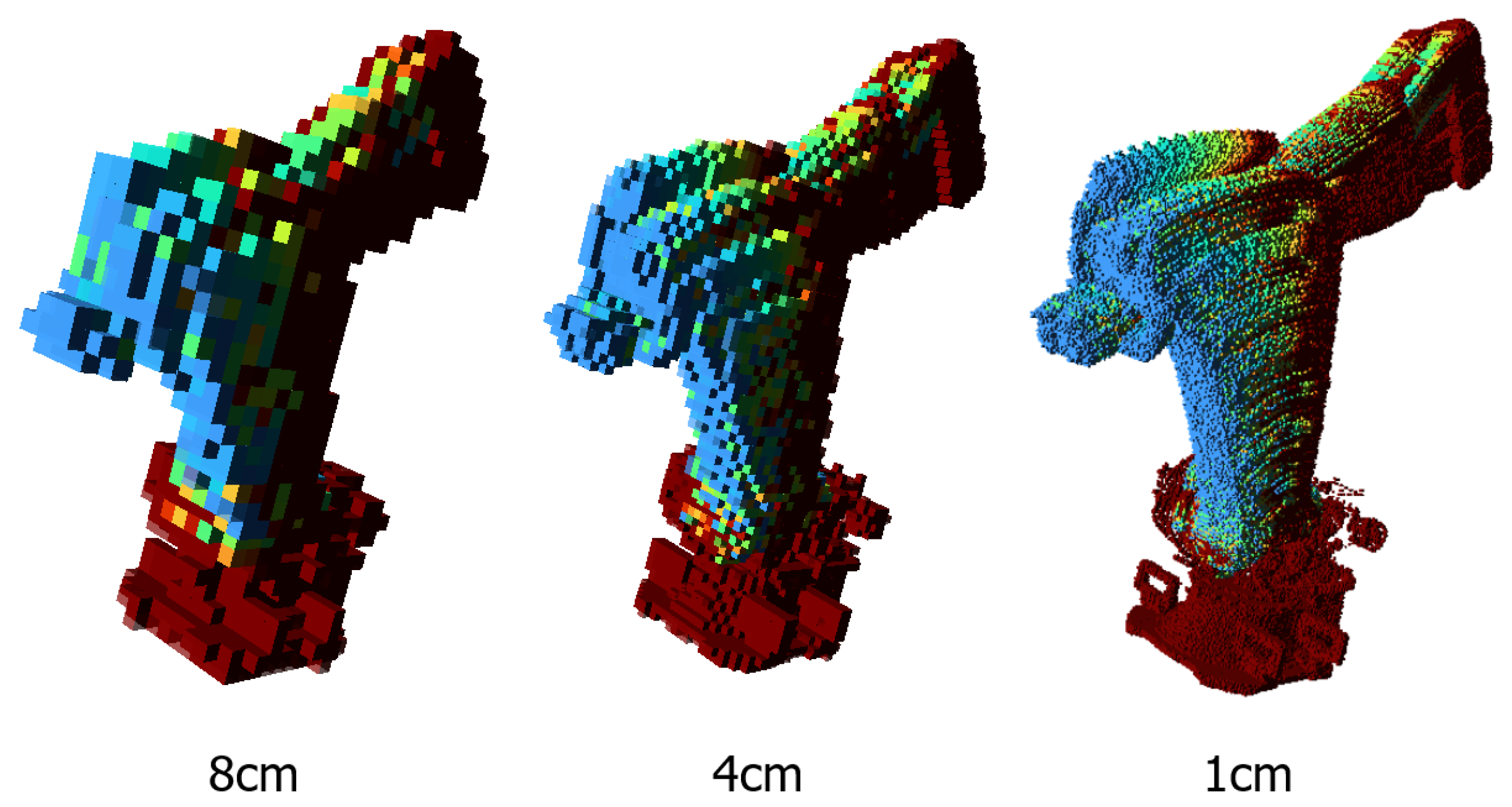
23]. The octree structure allows us to easily adapt the 3D space resolution depending on the application requirements. Starting with one root cube enclosing the entire area of interest, each node of the octree structure branches to eight sub-cubes (voxels) of the same size until the desired space resolution is reached. At the same time, occupancy information for the entire configuration space can be efficiently stored in a small-sized file. Each node encodes the occupancy probability, number of configurations that lead to the node being occupied and a list of the configurations that lead to node occupancy.
The occupancy map is generated either by using the trajectory or the full configuration space simulations. The base of the robot is positioned at the world origin. For each configuration of interest, we calculate the robot’s surface pointcloud and cast rays from the origin to the points [
23]. Since a single node can enclose multiple points, we take care to only count one hit per configuration for each node. This way, occupancy mapping is independent of density anomalies in the provided point clouds. The final result is a 3D occupancy probability map for the desired trajectory or for the entire configuration space. Additionally, we generate an independent occupancy map for each individual configuration of the set.
Figure 4 shows an example of the dynamic volumetric collision risk factor computed for a given pose of the robot and illustrating the risk for the upcoming time period
T, as described in
Section 3.2. With use of octrees in data representation, different resolution levels can be obtained according to the required level of visualization accuracy and memory limits.
4. AR/VR-Based Visualization
Visualization of the simulated environment and rendering of the safety zones is performed in the Unity3D game engine. The respective virtual industrial environment is created using a variety of available 3D objects, while the required functionality is achieved by C# scripts. For visualization in the virtual world, an Oculus Rift head-mounted display is employed, while navigation of the user around the environment and interaction with objects is rendered possible by the use of the Oculus controllers. In AR, Hololens 2 equipment is utilized.
4.1. Rendering in VR
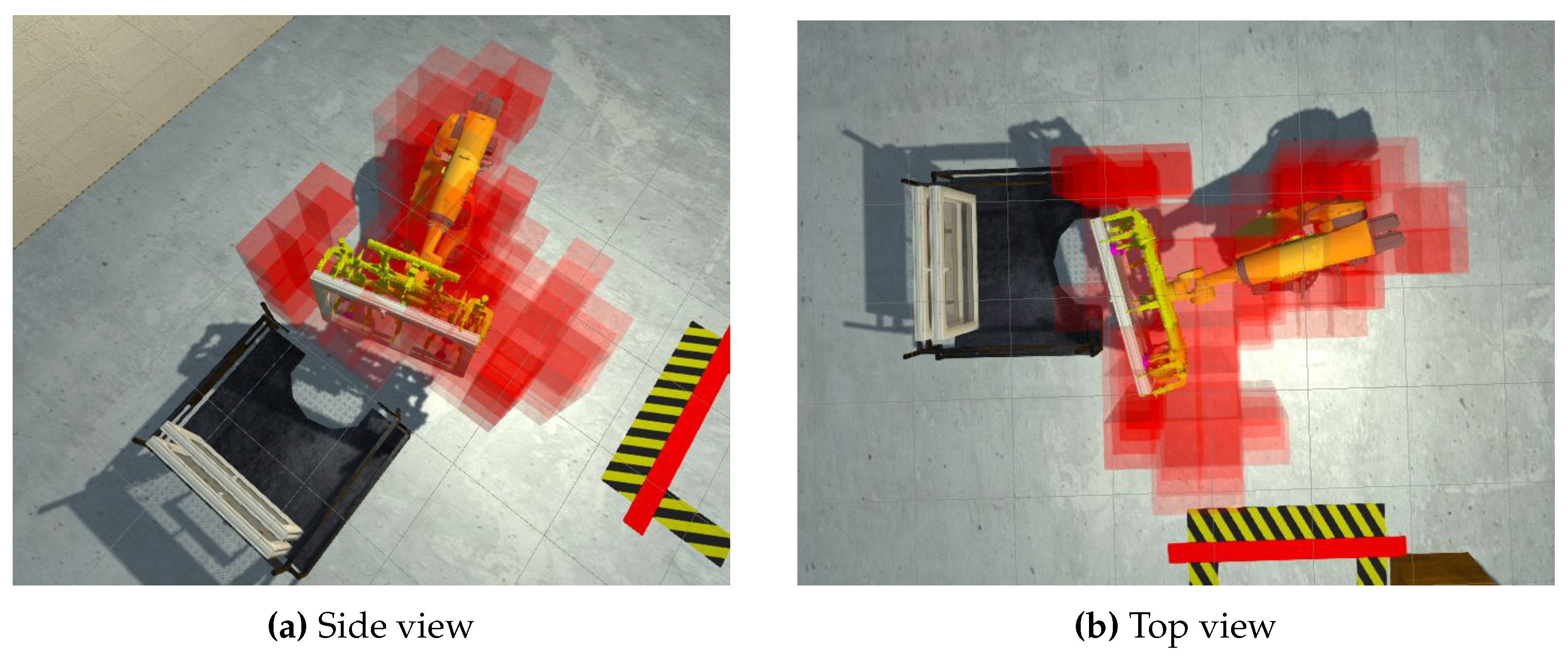
Visualization of the safety zones in VR is performed either as a stand-alone method (purely in Unity3D) through online tracking of the moving robot or by utilizing the previously presented occupancy mapping technique. In contrast to the dynamic occupancy mapping that provides a measure of risk for the upcoming timepoints, the former approach simply visualizes the unsafe zone (defined by the distance from the robot’s surface) for the current state. Specifically, the space around the 3D robotic model is filled with a large number () of small cubes, which are used as ‘sensors’ that detect a potential collision with the robotic parts during movement. The detection takes place at predefined time steps (a default value of 0.1 s between each record is selected). By computing which cubes are colliding with the robot’s parts, a set of points is generated that eventually sets the safety boundaries in every time step.
Visualization of the outcome of this method, as well as of the octree-based representation, is performed (both in VR and AR environments) by utilizing different shapes/entities, such as surface model cube and fog (by employing Unity’s particle system).
The dynamic rendering of safety zones (illustrating the collision risk within a fixed number of future steps) with the cube representation is shown in
Figure 5. The detailed experiment of the safety zone generation can be found online (
https://youtu.be/orHhr5X9N9U, accessed on 22 June 2023). A colorscale is used for the visualization of the cubes and corresponds to the percentage of time the robotic arm collides with each cube (within the look-ahead time
T) considering all the potential (defined) trajectories. This can be better observed in
Figure 6, in which the green cubes denoting the overall workspace of the robot have been hidden.
Another important factor is that due to VR’s nature, for each frame, the workload is doubled, as the image needs to be rendered twice (one for each eye), causing a significant drop in the overall performance (frames per second—fps), thus causing critical problems related to the overall experience and immersive capability of the simulation.
Due to this combination, the need to reduce information with a higher SNR (signal-to-noise ratio) was imminent in order to be able to provide a useful VR/AR experience, as most AR equipment will experience the same kind of performance problems.
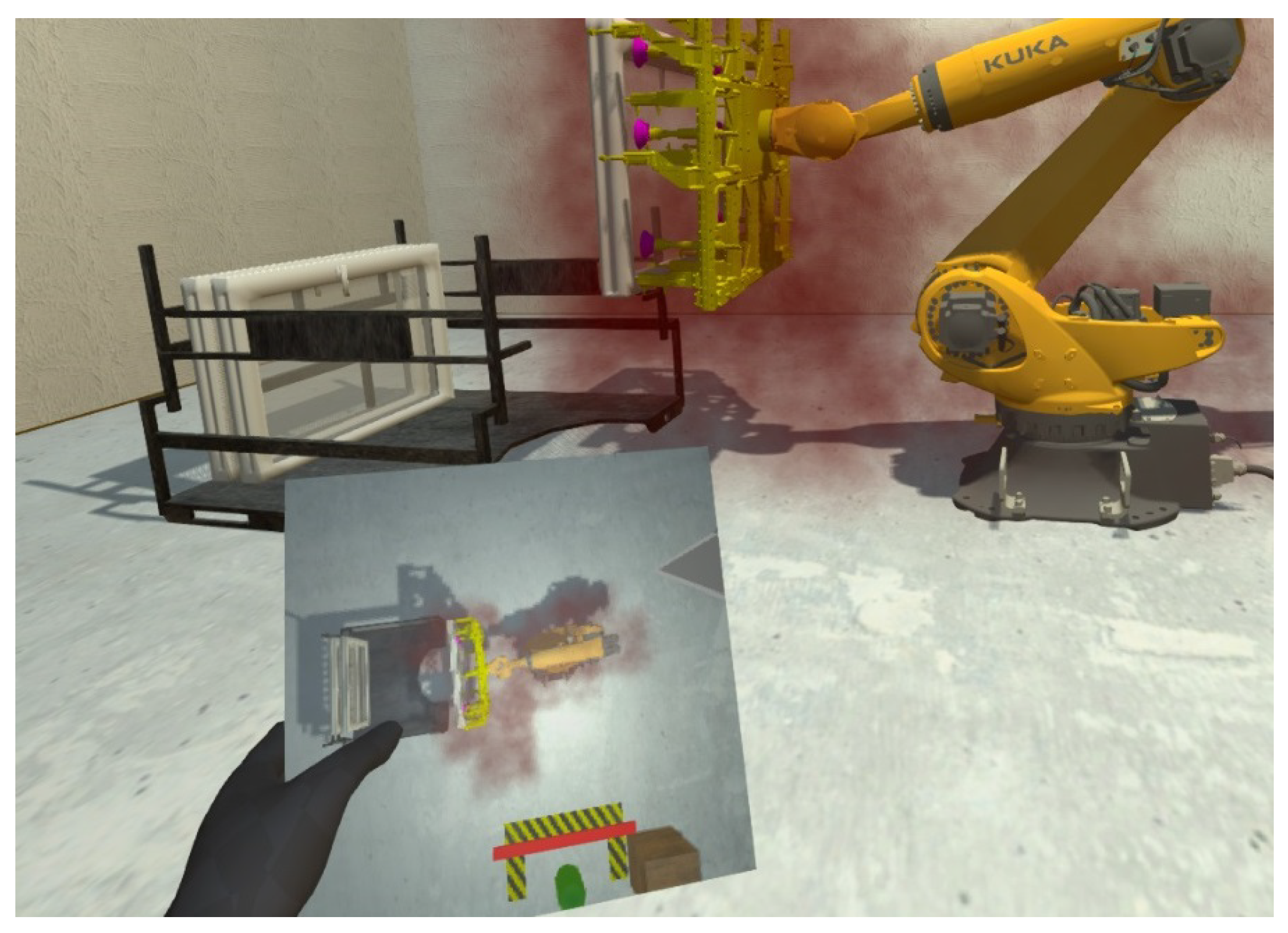
This means that, for example, in
Figure 7, the safety zone that is rendered concerns the position of the collided cubes from this step until the next four steps. In the dynamic area rendering, when considering the fog particle system, we also provided a top view of the safety zones, which is rendered in the board and is visible in
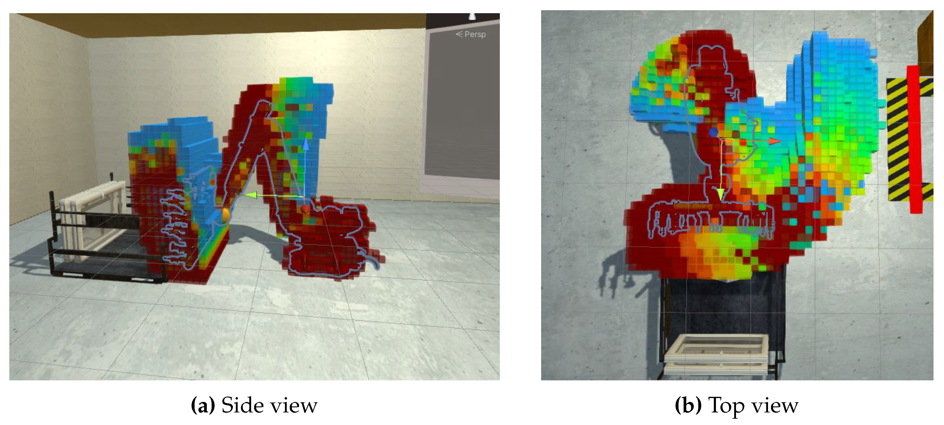
Figure 7. Likewise, we incorporate the provided information from an octree-based risk representation and render it with the cube method, as shown in
Figure 8.
4.2. Rendering in AR
The AR implementation is mostly focused on providing a tangible, mixed-reality result to enable the use of the digital twin and the rendered safety zones in an actual working environment through, e.g., the use of ArUco (Augmented Reality University of Cordoba) markers. To enable rendering in our simulation, we mainly exploit the data provided by the octree-based representation, as this depicts our introduced framework.
In order to deploy our VR Project into AR, the camera settings need to change to implement specific configuration profiles to map the Hololens 2 functionality inside the simulation. For this purpose, we need to replace the VR components inside our simulation with the respective AR ones. Then, one can deploy our project to Hololens 2 to visualize the respective results. In AR, given the movements of the robotic arm, our process can successfully visualize in real time (with a response of under 20 ms) the dynamic safety zones in order to inform a user close to the working space of the robotic arm. To run the aforementioned experiments we used a computer with 48 GB of RAM, an AMD Ryzen 9 3900X processor with 12 cores and an NVIDIA RTX 3090 graphics card.
This enables the process to be applied in real-world applications. Thus, by connecting to a robotic arm’s controller through a serial or a wireless connection, our system can have real-time updates of the movement of the robot and can accurately calculate the dynamic safety zones, reducing the need for external cameras covering the HRI workspace.
5. Discussion
In this paper, we present a framework for rendering static/dynamic safety zones in VR/AR. To emulate real robotic movement, we developed a custom simulation of the robot’s 3D digital model and placed it inside a virtual working environment. Probabilistic occupancy maps were used to estimate the risk of upcoming human–robot collisions based on all possible movements of the robot’s joints. In the case of specific assembly operations, the estimated spatiotemporal risk factor can be adapted to take into account only the programmed robotic motion trajectories, reducing the visualized risk for other configurations.
Furthermore, we introduced a state-aware collision risk prediction term that takes into account not only the robot’s pose but also the rotation of the robotic joints at each time step, thereby allowing prediction of the most-probable direction of movement. However, it should be noted that while the assumption of smooth changes in joints’ rotation holds for short time periods, it cannot be used for more long-term predictions. Moreover, this assumption is less valid when reaching the rotational limits (boundary points), thereby reducing confidence in the estimation in those cases. The above-mentioned argument can also be made regarding robots’ singularities. We assume that the inverse kinematics controller of the robot can successfully avoid singularities. However, the confidence in the estimation is significantly reduced due to the robot’s different behavior when close to a singularity pose.
6. Conclusions
In the future, we intend to combine the dynamic and the state-aware collision risk terms through appropriate temporally changing weights that will put more emphasis on the first or second term based on the need for short- or long-term prediction and the confidence of the estimation at each time step.
Moreover, in this work, the configuration of the robot at each time point is considered to be known, and the pose of the human operator is not taken into account. We are currently investigating the incorporation of 3D pose estimation algorithms based on visual information (through cameras placed in the workcell) that will allow the identification of imminent danger, i.e., when the operator enters a high-risk zone, and will accordingly adjust the rendered information (e.g., through more opaque or vivid colors or the triggering of sound). Even though our work does not focus on control systems that may affect or interrupt the robot motion, a future work direction could be the investigation of the effect of advanced interfaces in augmented reality that will increase the operators’ awareness and safety in the best possible way.
Author Contributions
Conceptualization, N.A. and G.P.; methodology, G.P.; software, G.M. and I.M.; validation, N.A., E.I.Z. and P.K.; formal analysis, E.I.Z.; investigation, N.A.; resources, G.P.; data curation, G.M. and I.M.; writing—original draft preparation, N.A. and G.P.; writing—review and editing, E.I.Z. and P.K.; visualization, G.M. and I.M.; supervision, P.K. and K.M.; project administration, K.M.; funding acquisition, K.M. All authors have read and agreed to the published version of the manuscript.
Funding
This work has received funding from the European Union’s Horizon 2020 Research and Innovation Programme under Grant Agreement No 871738—CPSoSaware: Crosslayer cognitive optimization tools & methods for the lifecycle support of dependable CPSoS.
Data Availability Statement
For this research work no new data were created. The presented simulation environment is currently publicly unavailable.
Conflicts of Interest
The authors declare no conflict of interest. The funders had no role in the design of the study; in the collection, analyses, or interpretation of data; in the writing of the manuscript; or in the decision to publish the results.
References
- Sharkawy, A.N.; Koustoumpardis, P.N. Human–robot interaction: A review and analysis on variable admittance control, safety, and perspectives. Machines 2022, 10, 591. [Google Scholar] [CrossRef]
- Liu, H.; Wang, Y.; Ji, W.; Wang, L. A context-aware safety system for human-robot collaboration. Procedia Manuf. 2018, 17, 238–245. [Google Scholar] [CrossRef]
- Vahrenkamp, N.; Arnst, H.; Wächter, M.; Schiebener, D.; Sotiropoulos, P.; Kowalik, M.; Asfour, T. Workspace analysis for planning human-robot interaction tasks. In Proceedings of the 2016 IEEE-RAS 16th International Conference on Humanoid Robots (Humanoids), Cancun, Mexico, 15–17 November 2016; pp. 1298–1303. [Google Scholar]
- Mohammed, A.; Schmidt, B.; Wang, L. Active collision avoidance for human–robot collaboration driven by vision sensors. Int. J. Comput. Integr. Manuf. 2017, 30, 970–980. [Google Scholar] [CrossRef]
- Sharkawy, A.N.; Koustoumpardis, P.N.; Aspragathos, N. Human–robot collisions detection for safe human–robot interaction using one multi-input–output neural network. Soft Comput. 2020, 24, 6687–6719. [Google Scholar] [CrossRef]
- Sharkawy, A.N.; Koustoumpardis, P.N.; Aspragathos, N. A recurrent neural network for variable admittance control in human–robot cooperation: Simultaneously and online adjustment of the virtual damping and Inertia parameters. Int. J. Intell. Robot. Appl. 2020, 4, 441–464. [Google Scholar] [CrossRef]
- Sharkawy, A.N.; Koustoumpardis, P.N.; Aspragathos, N. A neural network-based approach for variable admittance control in human–robot cooperation: Online adjustment of the virtual inertia. Intell. Serv. Robot. 2020, 13, 495–519. [Google Scholar] [CrossRef]
- Bimbo, J.; Pacchierotti, C.; Tsagarakis, N.G.; Prattichizzo, D. Collision detection and isolation on a robot using joint torque sensing. In Proceedings of the 2019 IEEE/RSJ International Conference on Intelligent Robots and Systems (IROS), Macau, China, 3–8 November 2019; pp. 7604–7609. [Google Scholar]
- Sharkawy, A.N.; Aspragathos, N. Human-robot collision detection based on neural networks. Int. J. Mech. Eng. Robot. Res 2018, 7, 150–157. [Google Scholar] [CrossRef]
- Pavlou, M.; Laskos, D.; Zacharaki, E.I.; Risvas, K.; Moustakas, K. XRSISE: An XR training System for Interactive Simulation and Ergonomics assessment. Front. Virtual Real. 2021, 2, 17. [Google Scholar] [CrossRef]
- Schnabel, R.; Klein, R. Octree-based Point-Cloud Compression. In Proceedings of the 3rd Eurographics/IEEE VGTC Conference on Point-Based Graphics, Boston, MA, USA, 29–30 July 2006; pp. 111–120. [Google Scholar]
- Choi, S.H.; Park, K.B.; Roh, D.H.; Lee, J.Y.; Mohammed, M.; Ghasemi, Y.; Jeong, H. An integrated mixed reality system for safety-aware human-robot collaboration using deep learning and digital twin generation. Robot.-Comput.-Integr. Manuf. 2022, 73, 102258. [Google Scholar] [CrossRef]
- Michalos, G.; Karagiannis, P.; Makris, S.; Tokçalar, Ö.; Chryssolouris, G. Augmented reality (AR) applications for supporting human-robot interactive cooperation. Procedia CIRP 2016, 41, 370–375. [Google Scholar] [CrossRef]
- Hietanen, A.; Pieters, R.; Lanz, M.; Latokartano, J.; Kämäräinen, J.K. AR-based interaction for human-robot collaborative manufacturing. Robot.-Comput.-Integr. Manuf. 2020, 63, 101891. [Google Scholar] [CrossRef]
- Krüger, M.; Weigel, M.; Gienger, M. Visuo-tactile AR for Enhanced Safety Awareness in Human-Robot Interaction. In Proceedings of the HRI 2020 Workshop on Virtual, Augmented and Mixed Reality for Human-Robot Interaction (VAM-HRI), Cambridge, UK, 23 March 2020. [Google Scholar]
- Vosniakos, G.C.; Ouillon, L.; Matsas, E. Exploration of two safety strategies in human-robot collaborative manufacturing using Virtual Reality. Procedia Manuf. 2019, 38, 524–531. [Google Scholar] [CrossRef]
- Adami, P.; Rodrigues, P.B.; Woods, P.J.; Becerik-Gerber, B.; Soibelman, L.; Copur-Gencturk, Y.; Lucas, G. Effectiveness of VR-based training on improving construction workers’ knowledge, skills, and safety behavior in robotic teleoperation. Adv. Eng. Inform. 2021, 50, 101431. [Google Scholar] [CrossRef]
- Dianatfar, M.; Latokartano, J.; Lanz, M. Concept for Virtual Safety Training System for Human-Robot Collaboration. Procedia Manuf. 2020, 51, 54–60. [Google Scholar] [CrossRef]
- Giorgini, M.; Aleotti, J. Visualization of AGV in virtual reality and collision detection with large scale point clouds. In Proceedings of the 2018 IEEE 16th International Conference on Industrial Informatics (INDIN), Porto, Portugal, 18–20 July 2018; pp. 905–910. [Google Scholar]
- Makhataeva, Z.; Zhakatayev, A.; Varol, H.A. Safety Aura Visualization for Variable Impedance Actuated Robots. In Proceedings of the 2019 IEEE/SICE International Symposium on System Integration (SII), Paris, France, 14–16 January 2019; pp. 805–810. [Google Scholar] [CrossRef]
- Rusu, R.B.; Cousins, S. 3D is here: Point Cloud Library (PCL). In Proceedings of the IEEE International Conference on Robotics and Automation (ICRA), Shanghai, China, 9–13 May 2011. [Google Scholar]
- Cheng, H.; Gupta, K.C. A study of robot inverse kinematics based upon the solution of differential equations. J. Robot. Syst. 1991, 8, 159–175. [Google Scholar] [CrossRef]
- Hornung, A.; Wurm, K.M.; Bennewitz, M.; Stachniss, C.; Burgard, W. OctoMap: An Efficient Probabilistic 3D Mapping Framework Based on Octrees. Auton. Robot. 2013, 34, 189–206. [Google Scholar] [CrossRef]
| Disclaimer/Publisher’s Note: The statements, opinions and data contained in all publications are solely those of the individual author(s) and contributor(s) and not of MDPI and/or the editor(s). MDPI and/or the editor(s) disclaim responsibility for any injury to people or property resulting from any ideas, methods, instructions or products referred to in the content. |
© 2023 by the authors. Licensee MDPI, Basel, Switzerland. This article is an open access article distributed under the terms and conditions of the Creative Commons Attribution (CC BY) license (https://creativecommons.org/licenses/by/4.0/).


 ,
, 


