Abstract
A maglev train is a new type of high-speed railway transportation. A high-temperature superconducting (HTS) maglev system is one of the typical representatives in the field of maglev trains. In order to research the levitation characteristics of an HTS maglev train, the force characteristics and operation performance of the train were researched. However, at present, there is still no research that simulates the real load situation of a running maglev train while analyzing the suspension frame. Regarding this issue, in this paper, the suspension frame is simulated and analyzed to simulate the real load situation of a maglev train. The results show that the suspension frame of an HTS maglev train can bear corresponding loads under different working conditions, and its strength and stiffness meet the requirements of use, safety, and reliability. Random irregularity in the permanent magnet track of an HTS maglev train route is inevitable, which will make the suspension frame produce a vibration response under different running speeds of the train. Vibration of the suspension frame of the train is inevitable. For the electromagnetic levitation (EMS) train, researchers considered monitoring the train status. However, at present, there is no suspension frame condition monitoring device for an HTS maglev train. In addition, the levitation height of the suspension frame affects the suspension performance and traction performance of the vehicle, and the vibration of the suspension frame during running affects the dynamic performance and safety of the suspension frame and the vehicle. Regarding the issue above, through a suspension frame monitoring system, the lateral and vertical vibration acceleration and levitation height of the suspension frame are monitored at different train speeds. The maximum value of vibration acceleration and the fluctuation range of levitation height are within the safe range. It is verified that the simulation analysis of the suspension frame of an HTS maglev train is correct, the suspension frame is safe, and the train can run safely.
1. Introduction
The modern high-speed railway has the advantages of fast speed, large transportation capacity, and all-weather running. As a new type of high-speed railway transportation, the maglev train has the advantages of low vibration, fast starting and braking, strong climbing ability, safety, comfort, less maintenance work and cost, low energy consumption, and low environmental pollution. It is one of the main directions of world transportation development in the 21st century. As one of the typical representatives in the field of maglev, the HTS maglev system has the advantage of self-stable suspension without external control. In terms of technical principles, it has the advantages of energy savings, environmental protection, stability, reliability, and a wide speed range (which can meet the requirements of running at medium and low speed, high speed, and even ultra-high speed). It is an emerging technology with great development potential. Unlike electromagnetic levitation (EMS), which relies on the control system to maintain its own stability, and electric levitation (EDS), which relies on speed to maintain its suspension, the HTS maglev can maintain a stable suspension without any control system or running speed [1,2,3]. With this feature, HTS maglev has been widely studied in the field of rail transit [4,5,6,7] and magnetic bearings [8,9,10].
At present, China, Germany, Brazil, Italy, and Russia have carried out a large amount of scientific research and have developed HTS maglev vehicles [11]. HTS maglev trains are becoming a hot research topic in the field of new rail transit.
In 1988, it was found that high-temperature superconductors can be stably suspended on permanent magnets [12,13]. Researchers considered using this physical phenomenon in the suspension system of maglev trains. Similar to the contact force in the wheel rail-train system, the maglev force of the HTS Maglev vehicle can be divided into levitation force and guidance force. The levitation force above a single magnet tested at different heights has hysteresis characteristics [14]. In 1999, researchers tested and analyzed the levitation force and guiding force under field cooling and zero field-cooling conditions [15]. Because the levitation force and guiding force of an HTS maglev are nonlinear, there are also many nonlinear dynamic phenomena, such as period-doubling bifurcation, 1/2 harmonic resonance, chaos, and jump [16,17,18,19,20,21].
In order to study the levitation characteristics of an HTS maglev train, the researchers studied the stress characteristics and running performance [22]. However, at present, there is no research simulating the real load situation of maglev train operation while analyzing the suspension frame. In particular, strength analysis and calculation are carried out under AW3 extreme working conditions with a full train load, and the stress distribution of the suspension frame is analyzed while parked (suspension state) as well as during various traction and braking conditions.
For the electromagnetic levitation (EMS) train, researchers considered monitoring the train status [23,24]. However, at present, there is no suspension frame status monitoring device for HTS maglev trains. There is no monitoring of the levitation height of the suspension frame, and there is no monitoring of the vibration of the suspension frame during the running of the train. The levitation height of the suspension frame of an HTS maglev train affects the suspension performance and traction performance of the vehicle, and the vibration magnitude and frequency during running affect the dynamic performance, safety, and comfort of the suspension frame and the vehicle. If the levitation height of the suspension frame of the HTS maglev train is lower than a certain safety limit value, the vehicle will not be able to be suspended and towed and will cause interference and friction between the suspension system and the permanent magnet track, which will damage the suspension system and seriously affect vehicle safety. If the vibration frequency of the suspension frame is too large, it will affect the dynamic performance, safety, and comfort of the suspension frame and the vehicle.
To meet this challenge, the main insights and contributions of this paper are summarized as follows.
- (1)
- The suspension frame of an HTS maglev train is simulated and analyzed to simulate the real load situation of a maglev train. The results show that the suspension frame of the HTS maglev train can bear corresponding loads under different working conditions.
- (2)
- A real-time online monitoring method for the suspension frame of the HTS maglev train is proposed. The levitation height and vibration acceleration of the suspension frame can be monitored remotely and wirelessly when the train is running.
- (3)
- The maximum value of vibration acceleration and the fluctuation range of levitation height are within the safe range. It is verified that the simulation analysis of the suspension frame of the HTS maglev train is correct, the suspension frame is safe, and the train can run safely.
In Section 2 of the paper, the suspension frame of an HTS maglev train is simulated and analyzed to simulate the real load situation of the maglev train. Section 3 contains the results and discussion of the experiment on online monitoring of the suspension frame of an HTS maglev train. The conclusion is in Section 4.
2. Simulation Analysis of the Suspension Frame of an HTS Maglev Train
Using ANSYSWorkbench finite element simulation software, the suspension frame is analyzed according to UIC515-4 “Passenger rolling stock Trailer bogies-running gear Bogie frame structure strength tests”, so as to simulate the real load situation of the maglev train during running.
In order to explore the dynamics characteristic of HTS maglevs, H. D. Wang and H. T. Li built a levitation force model [25,26]
where μ, α, ω, γ are constant parameters, while z is levitation height. Flev represents the levitation force, which is nonlinear, making an HTS maglev a complex nonlinear dynamic system. This system is composed of a permanent magnet track, suspension frame, linear traction motor, and superconducting dewar. ANSYSWorkbench finite element simulation software can simulate the influence of various forces on the suspension frame under different working conditions, including the force of the carbody load on the rubber spring of the suspension frame; the normal force between the primary and secondary linear motors; the levitation force of superconducting dewar; the weight of the suspension frame; the weight of the dewar; etc. Through simulation, the software can analyze whether the strength and stiffness of the suspension frame meet the requirements.
The suspension frame is made of 6061-T4 aluminum alloy, with a yield strength ≥ 227 Mpa. Select AW3 extreme working conditions for strength analysis and calculation were choses. Research and analysis of the stress distribution of the suspension frame under parking (suspension state), traction working condition 3, traction working condition 4, traction working condition 5, traction working condition 8, and braking were conducted. In addition, in order to investigate the influence of normal force on the linear motor, dewar gravity, and an unbalanced load on the dewar beam and permanent magnet track spacing, the deformation of the dewar beam needs to be analyzed. The traction rod needs to transmit traction force, so it is necessary to analyze whether the traction rod seat can meet the requirements.
2.1. Suspension Frame Structure Data
Onboard load:
Overall mass of suspension frame:
Maximum running speed:
Maximum traction acceleration:
Maximum braking acceleration:
2.2. Basic Load Calculation of Suspension Frame
According to UIC515-4 “Passenger rolling stock Trailer bogies-running gear Bogie frame structure strength tests”, the load of the suspension frame is calculated, and the load combination is carried out according to the actual running state of the train to simulate the real running of the maglev train.
- (1)
- Abnormal working condition load:
Vertical load applied on the side beam of each suspension frame:
- (2)
- Load under main running conditions:
Vertical load applied on the side beam of each suspension frame:
- (3)
- Traction load:
The maglev train is in an acceleration state, and the thrust provided by the motor is
Suspension frame traction inertia load:
Onboard traction inertia load:
The maximum air resistance of the train during acceleration is:
According to the above formula, the air resistance during maglev running is far less than the thrust during acceleration, and the wind load is not considered here.
- (4)
- Braking load:
The braking acceleration of the maglev train is 0.5 m/s2, which is similar to the traction load, so the braking force of the suspension frame is
Suspension frame braking inertia load:
Onboard braking inertia load:
2.3. Finite Element Analysis Model
The mesh division of the finite element model is shown in Figure 1. The model weight is m2 = 725 kg, and the actual weight of the structure is m1 = 740 kg. (the total dewar weight is not included here. Dewar gravity acts on the dewar beam on boundary conditions).
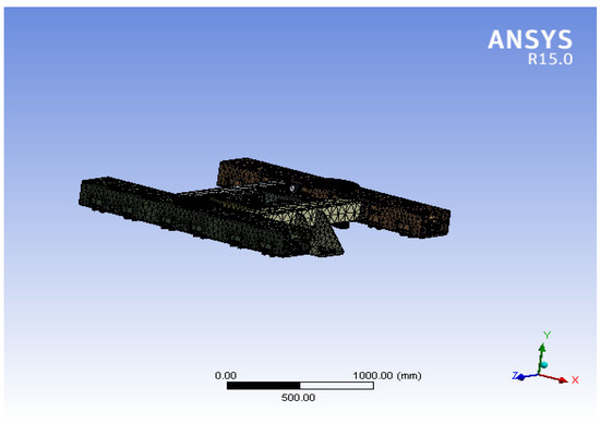
Figure 1.
Finite element model of suspension frame.
2.4. Proportion of Distributed Load
Dead weight load of suspension frame:
Inertial load of the suspension frame
2.5. Load Combination and Calculation Conditions
2.5.1. Load Combination
According to UIC515-4 “Passenger rolling stock Trailer bogies-running gear Bogie frame structure strength tests” and other standards, the load of the suspension frame is calculated, and the load combination is carried out according to the actual running state of the train to simulate the real running state of a maglev train, as shown in Table 1.

Table 1.
Load conditions under different working conditions.
As the frame is symmetrical, it can be seen that the conditions of working conditions 4 and 6 are the same, and the conditions of working conditions 5 and 7 are the same. When the wind load is ignored, acceleration under braking conditions and traction conditions is the same, and the direction is opposite. Because the suspension frame structure is symmetrical, it can be seen that the conditions under conditions 8 and 9 are the same.
2.5.2. Calculation of Each Working Condition
The coordinates in the XYZ direction are shown in Figure 1. In this paper, the Y axis is the vertical axis. The negative direction of the Y axis is the gravity direction, as shown in Table 2.
Table 2.
Scale factor and forces under different working conditions.
2.6. Static Strength and Fatigue Strength Calculation Results
Through workbench calculation, the results are as shown in Table 3.
Table 3.
Strength calculation results under different load conditions.
2.7. Finite Element Analysis
2.7.1. Parking (Suspended)
The grid division adopts the grid automatically, which is then divided by the workbench. Under the Size menu, pull the Relevance option to 100, and select medium for the Relevance Center. The automatic mesh type is tetrahedral, which is divided into 644,234 nodes and 352,254 units. At the same time, the dewar beam is locally refined.
As shown in Figure 2,the boundary conditions are the force exerted by the onboard load on the two rubber springs; the weight of the suspension frame (load scale factor is considered here); the set elastic support surface or fixed support surface (when considering the influence of normal force on the linear motor, dewar gravity and an unbalanced load on the dewar beam and permanent magnet track, the support surface is regarded as a spring; when simply considering the influence of material deformation, the support surface is regarded as a fixed support surface); the acting force of the weight of the dewar on the dewar beam; and the normal force between the primary and secondary linear motors.
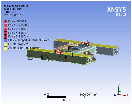
Figure 2.
Loading diagram of suspension frame boundary conditions under parking (suspension) state.
As shown in Figure 3, the maximum stress is located at the dewar beam connection, and the maximum stress is 3.6 MPa, which is far less than the allowable stress, meeting the requirements.
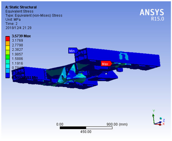
Figure 3.
Stress nephogram of suspension frame under parking (suspension) state.
As shown in Figure S1, the influence of normal force on the linear motor, dewar gravity, and an unbalanced load on the distance between the dewar beam and the permanent magnet track was investigated. In order to separately investigate the influence of stress on the deformation of the material, after setting the support surface as fixed, the deformation is shown in Figure S2. The support form ensures that the stiffness of the dewar beam is large enough.
2.7.2. Parking (Support Wheel Support Status)
The grid division adopts the grid automatically, which is then divided by the workbench. Under the Size menu, pull the Relevance option to 100, and select medium for the Relevance Center. The automatic mesh type is tetrahedral, which is divided into 644,234 nodes and 352,254 units. At the same time, the dewar beam is locally refined.
As shown in Figure 4, the boundary conditions are the force exerted by the onboard load on the two rubber springs; the weight of the suspension frame (load scale factor is considered here); the constraint of the supporting wheel in Y direction; the normal force between the primary and secondary linear motors; the acting force of the weight of the dewar on the dewar beam and the normal force between the primary and secondary linear motors.
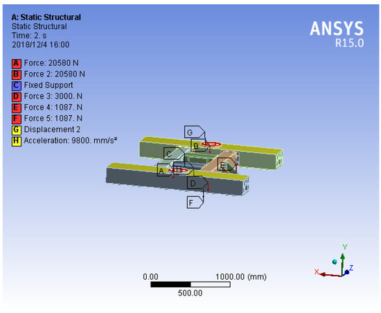
Figure 4.
Loading diagram of suspension frame boundary conditions under parking (support wheel support) state.
As shown in Figure 5, the overall stress of the suspension frame is small, and the maximum stress is located at the support wheel, with local stress concentration. The maximum stress is 20 MPa, less than the allowable stress, which meets the requirements.
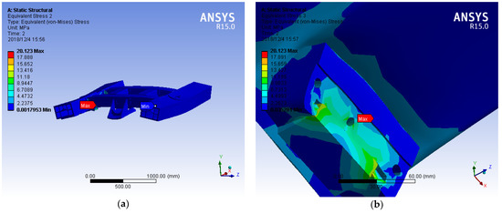
Figure 5.
Under parking (supported by supporting wheel): (a) Stress nephogram of suspension frame; (b) Partially enlarged view of suspension frame stress.
Since it is already supported by the supporting wheel, the deformation at this time is shown in Figure S3. The deformation on both sides is symmetrical, which conforms to the qualitative analysis, and the structural support form ensures its sufficient stiffness.
2.7.3. Traction Condition (Condition 3)
The grid division adopts the grid automatically, which is then divided by the workbench. Under the Size menu, pull the Relevance option to 100, and select medium for the Relevance Center. The automatic mesh type is tetrahedral, which is divided into 644,234 nodes and 352,254 units. At the same time, the dewar beam is locally refined.
As shown in Figure 6, The boundary conditions are the force exerted by the onboard load on the two rubber springs; the force exerted by the onboard on the longitudinal stop plate; the weight of the suspension frame (load scale factor is considered here); acceleration corresponding to an inertial load of the suspension frame (load scale factor is considered here); the set elastic support surface or fixed support surface (when considering the influence of dewar gravity and an unbalanced load on the dewar beam and the permanent magnet track, the support surface is regarded as a spring; when simply considering the influence of material deformation, the support surface is regarded as a fixed support surface); the acting force of the weight of the dewar on the dewar beam; and the normal force between the primary and secondary linear motors. In order to keep the suspension frame basically horizontal, its rotation along the Z axis is limited.
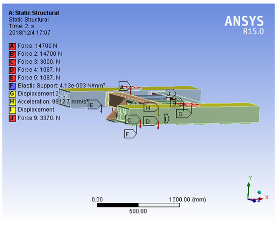
Figure 6.
Boundary condition loading diagram of suspension frame under traction condition (condition 3).
As shown in Figure 7, the maximum stress is located at the connection between the reaction plate and the beam, and the maximum stress is 3.9 MPa, which is far less than the allowable stress, meeting the requirements.
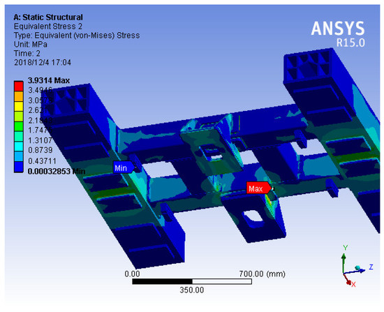
Figure 7.
Stress nephogram of suspension frame under traction condition (condition 3).
As shown in Figure S4, the influence of normal force on the linear motor, dewar gravity, and an unbalanced load on the distance between the dewar beam and the permanent magnet track was investigated. In order to separately investigate the influence of stress on the deformation of the material, after setting the support surface as fixed, the deformation is shown in Figure S5.
The support form ensures that the stiffness of the dewar beam is large enough.
2.7.4. Traction Condition (Condition 4)
The grid division adopts the grid automatically, which is then divided by the workbench. Under the Size menu, pull the Relevance option to 100, and select medium for the Relevance Center. The automatic mesh type is tetrahedral, which is divided into 644,234 nodes and 352,254 units. At the same time, the dewar beam is locally refined.
As shown in Figure 8, the boundary conditions are the force exerted by the onboard load on the two rubber springs; the force exerted by the onboard on the longitudinal stop plate; the weight of the suspension frame (load scale factor is considered here); acceleration corresponding to an inertial load of the suspension frame (load scale factor is considered here); the set elastic support surface or fixed support surface (when considering the influence of dewar gravity and an unbalanced load on the dewar beam and the permanent magnet track, the support surface is regarded as a spring; when simply considering the influence of material deformation, the support surface is regarded as a fixed support surface); the acting force of the weight of the dewar on the dewar beam; and the normal force between the primary and secondary linear motors. In order to keep the suspension frame basically horizontal, its rotation along the Z axis is limited.
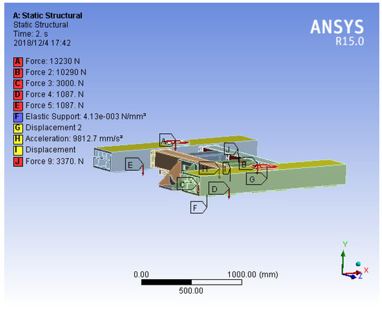
Figure 8.
Boundary condition loading diagram of suspension frame under traction condition (condition 4).
As shown in Figure 9, the maximum stress is located at the dewar beam, and the maximum stress is 3.2 MPa, which is far less than the allowable stress, meeting the requirements.
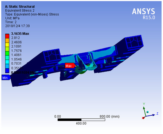
Figure 9.
Stress nephogram of suspension frame under traction condition (condition 4).
As shown in Figure S6, the influence of the normal force on the linear motor, dewar gravity, and an unbalanced load on the distance between the dewar beam and the permanent magnet track was investigated. In order to separately investigate the influence of stress on material deformation, the deformation of the support surface is set as shown in Figure S7 after it is fixed. In condition 4, considering the sinking and floating coefficient, the forces on both sides are not completely symmetrical, so the deformation is shown in Figure S7. Because of the support form, the stiffness of the dewar beam is large enough.
2.7.5. Traction Condition (Condition 5)
The grid division adopts the grid automatically, which is then divided by the workbench. Under the Size menu, pull the Relevance option to 100, and select medium for the Relevance Center. The automatic mesh type is tetrahedral, which is divided into 644,234 nodes and 352,254 units. At the same time, the dewar beam is locally refined.
As shown in Figure 10, the boundary conditions are the force exerted by the onboard load on the two rubber springs; the force exerted by the onboard on the longitudinal stop plate; the weight of the suspension frame (load scale factor is considered here); acceleration corresponding to an inertial load of the suspension frame (load scale factor is considered here); the set elastic support surface or fixed support surface (when considering the influence of dewar gravity and an unbalanced load on the dewar beam and the permanent magnet track, the support surface is regarded as a spring; when simply considering the influence of material deformation, the support surface is regarded as a fixed support surface); the acting force of the weight of the dewar on the dewar beam; and the normal force between the primary and secondary linear motors. In order to keep the suspension frame basically horizontal, its rotation along the Z axis is limited.
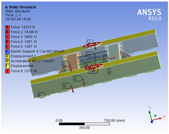
Figure 10.
Boundary condition loading diagram of suspension frame under traction condition (condition 5).
As shown in Figure 11, the maximum stress is located at the dewar beam, and the maximum stress is 3.3 MPa, which is far less than the allowable stress, meeting the requirements.
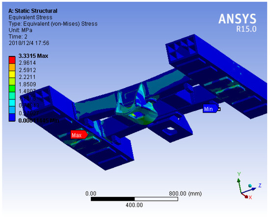
Figure 11.
Stress nephogram of suspension frame under traction condition (condition 5).
As shown in Figure S8, the influence of the normal force on the linear motor, dewar gravity, and an unbalanced load on the distance between the dewar beam and the permanent magnet track was investigated. In order to separately investigate the influence of stress on the deformation of the material, after setting the support surface as fixed, the deformation is shown in Figure S9.
In condition 5, considering the sinking and floating coefficient, the forces on both sides are not completely symmetrical, so the deformation is shown in Figure S9. This support form ensures that the stiffness of the dewar beam is large enough.
2.7.6. Traction Condition (Condition 8)
The grid division adopts the grid automatically, which is then divided by the workbench. Under the Size menu, pull the Relevance option to 100, and select medium for the Relevance Center. The automatic mesh type is tetrahedral, which is divided into 644,234 nodes and 352,254 units. At the same time, the dewar beam is locally refined.
As shown in Figure 12, the boundary conditions are the force exerted by the onboard load on the two rubber springs; the force exerted by onboard on the longitudinal stop plate; the weight of the suspension frame (load scale factor is considered here); acceleration corresponding to the inertial load of the suspension frame (load scale factor is considered here); the set elastic support surface or fixed support surface (when considering the influence of dewar gravity and an unbalanced load on the dewar beam and the permanent magnet track, the support surface is regarded as a spring; when simply considering the influence of material deformation, the support surface is regarded as a fixed support surface); The acting force of the weight of the dewar on the dewar beam; and the normal force between the primary and secondary linear motors. In order to keep the suspension frame horizontal, its rotation along the Z axis is limited.
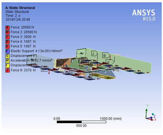
Figure 12.
Loading diagram of boundary conditions of suspension frame under traction condition (condition 8).
As shown in Figure 13, the maximum stress is located at the dewar beam, and the maximum stress is 4.1 MPa, which is far less than the allowable stress, meeting the requirements.
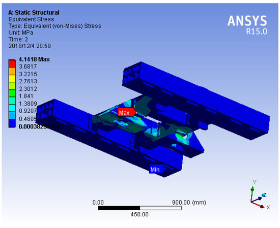
Figure 13.
Stress nephogram of suspension frame under traction condition (condition 8).
As shown in Figure S10, the influence of normal force on the linear motor, dewar gravity, and an unbalanced load on the distance between the dewar beam and the permanent magnet track was investigated.
In order to separately investigate the influence of stress on material deformation, the deformation of the support surface is set as shown in Figure S11 after it is fixed. The support form ensures that the stiffness of the dewar beam is large enough.
2.7.7. Braking Conditions
The grid division adopts the grid automatically, which is then divided by the workbench. Under the Size menu, pull the relevant option to 100, and select medium for the Relevance Center. The automatic mesh type is tetrahedral, which is divided into 644,234 nodes and 352,254 units. At the same time, the dewar beam is locally refined.
As shown in Figure 14, the boundary conditions are the force exerted by the onboard load on the two rubber springs; the force exerted by onboard on the longitudinal stop plate; the weight of the suspension frame (load scale factor is considered here); acceleration corresponding to an inertial load of the suspension frame (load scale factor is considered here); the set elastic support surface or fixed support surface (when considering the influence of dewar gravity and an unbalanced load on the dewar beam and the permanent magnet track, the support surface is regarded as a spring; when simply considering the influence of material deformation, the support surface is regarded as a fixed support surface); the acting force of the weight of the dewar on the dewar beam; braking force; and the normal force between the primary and secondary linear motors. In order to keep the suspension frame horizontal, its rotation along the Z axis is limited.
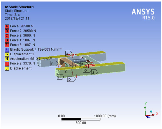
Figure 14.
Loading diagram of suspension frame boundary conditions under braking conditions.
As shown in Figure 15, the maximum stress is located at the dewar beam, and the maximum stress is 3.6 MPa, which is far less than the allowable stress, meeting the requirements.
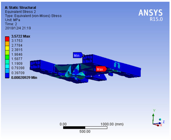
Figure 15.
Stress nephogram of suspension frame under braking condition.
As shown in Figure S12, the influence of the normal force of the linear motor, dewar gravity, and an unbalanced load on the distance between the dewar beam and the permanent magnet track was investigated. In order to separately investigate the influence of stress on the deformation of material, after the support surface is fixed, the deformation is shown in Figure S13. The support form ensures that the stiffness of the dewar beam is large enough.
2.7.8. Check of Traction Seat
The traction seat is welded with steel plates, made of Q345, with a yield strength ≥ 345 MPa. Under AW3 working conditions, the main force on the traction seat is 3370 N in a longitudinal direction. The car body and traction seat are fixed through the connecting hole. The strength and stiffness are checked as follows. The strength is as shown in Figure 16.
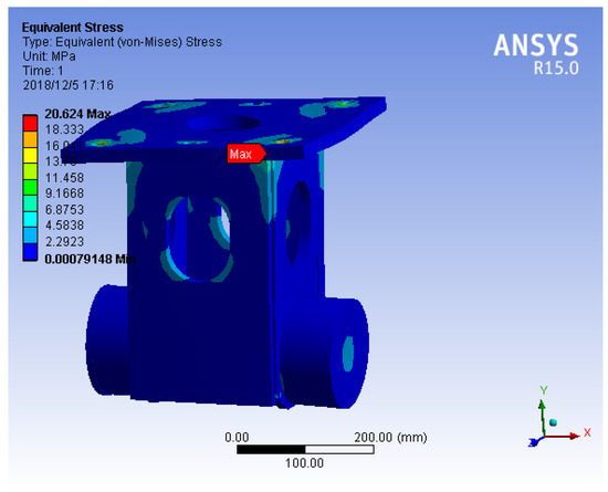
Figure 16.
Traction seat stress nephogram.
It can be seen from the figure that the maximum stress is 21 MPa, which is far less than the allowable stress, meeting the requirements.
The stiffness is shown in Figure S14. According to the figure, the deformation is small and meets the requirements.
The above simulation analysis simulates the real load condition of a running maglev train. The strength analysis and calculation are carried out under AW3 extreme conditions. The simulation results show that the stress distribution of the suspension frame is consistent under extreme conditions. The stress distribution of the suspension frame is similar under parking (suspension state), traction condition 3, traction condition 4, traction condition 5, traction condition 8, and braking condition. The maximum stress position of the suspension frame is concentrated at the connection of the reaction plate and dewar beam, but the stress value does not exceed the yield limit value of the material. The maximum stress of the suspension frame during parking (supported by the supporting wheel) is concentrated at the supporting wheel, and the stress value does not exceed the yield limit value of the material. In order to investigate the influence of the normal force of the linear motor, dewar gravity, and an unbalanced load on the dewar beam and the distance between the permanent magnet track, the dewar beam deformation was investigated. The results show that the deformation of the dewar beam is very small, and the stiffness of the dewar beam is large enough. In addition, the traction rod needs to transmit traction force, so whether the traction rod seat can meet the use requirements is extremely important. According to the stress condition of the traction pull rod seat, a corresponding analysis was carried out. The results show that the maximum stress of the traction seat is far less than the allowable stress of the material, the strength check is qualified, and the deformation is small, which can meet the use requirements.
To sum up, the suspension frame of an HTS maglev train can bear corresponding loads under different working conditions, and its strength and stiffness meet the requirements of use, and it is safe and reliable.
3. Online Monitoring of HTS Maglev Train
An HTS maglev track is an Nd-Fe-B permanent magnet track, and it is composed of a large number of small permanent magnets. There will be defects in the production and construction of small permanent magnets, and random irregularity of the permanent magnet track is inevitable. When a large number of small permanent magnets form the magnetic track, the irregularity of the magnetic track will be caused by factors such as the production and assembly process and the deformation of the magnetic mutual repulsion stress. The irregularity of the magnetic track will affect the running stability of an HTS maglev train.
In the actual running of an HTS maglev train, the suspension frame will produce a vibration response under the random irregularity of the track at different train speeds. Due to the excitation of track irregularity and guide rail deformation, the vibration is usually vertical and lateral coupling. The lateral response of the train is as important as the vertical response. Since the lateral vibration of the suspension frame will affect the stability and comfort of the train, it is necessary to measure the lateral vibration of the suspension frame. In addition, the strong lateral vibration may lead to the derailment of an HTS maglev train, which will lead to disastrous consequences. In the actual engineering research, we reduced the vibration of the suspension frame during train runs by reducing the normal force of the linear traction motor and reducing the vibration of the carbody when the train is running by installing a rubber spring between the suspension frame and the carbody. However, the train will still produce a vibration response when the track is randomly irregular, so measuring the vibration acceleration data of the suspension frame is an important factor to evaluate the risk of a collision between the HTS maglev train and the track.
During the actual running of an HTS maglev system, track irregularity and the vertical and lateral coupling effect of the maglev force and guidance force provided by the suspension system are important factors affecting the dynamic characteristics of the train, and track irregularity is the main excitation of the train. The levitation force measured by the levitation system of the permanent magnet track at different levitation heights has hysteresis characteristics. Because the levitation force and guiding force of high-temperature superconducting maglevs are nonlinear, many nonlinear dynamic phenomena occur in high-temperature superconducting maglevs, such as period-doubling bifurcation, 1/2 harmonic resonance, chaos, and jump phenomenon. The asymmetric magnetic field will significantly affect the rotation of the block.
According to Equation (1), in the levitation force model of an HTS maglev train, the levitation height will directly affect the levitation force, At the same time, the levitation force will directly affect the vibration acceleration of the suspension frame. Therefore, it is necessary to monitor the levitation height and vibration acceleration of the suspension frame.
The status monitoring device of the suspension frame of an HTS maglev train includes a levitation height acquisition system and a suspension frame vibration status acquisition system.
Principles of on-board monitoring systems (see Figure 17, Figure 18 and Figure 19): the laser displacement sensor measures the levitation height between the suspension frame and the magnetic rail. The three-way acceleration sensor measures the vibration amplitude of the suspension frame. The four three-way acceleration sensors connect the signal to the constant current source for signal conditioning, which turns into a standard analog quantity, and then transmits the signal to the multi-channel data collector. The data collector simultaneously collects the signals of the four laser displacement sensors (standard analog quantity voltage output type). The data collector is connected to the industrial computer through a USB to store the test data. The industrial control computer transmits the data to the ground host through wireless vehicle ground communication. The industrial control computer wirelessly transmits the data to the ground host through the wireless AP, the total delay of train ground communication shall not exceed 50 ms, and the average bandwidth shall not be less than 50 Mbps.
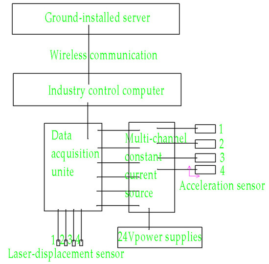
Figure 17.
Schematic diagram of on-board monitoring system.
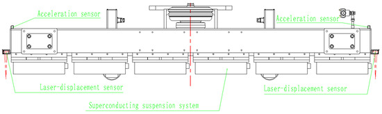
Figure 18.
Installation layout of acceleration sensor and levitation height sensor.
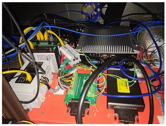
Figure 19.
Signal acquisition system installed on the train.
As shown in Figure 20, the levitation height acquisition system collects data on the levitation height of the suspension frame of an HTS maglev train in real time through the high-precision laser displacement sensor and can use the same acquisition card and data acquisition software with the three-way acceleration sensor. The laser displacement sensor is installed at the four ends of the suspension frame to measure the levitation height in the vertical direction of the four ends of the suspension frame. The installation position of the laser displacement sensor in the vertical direction of the suspension frame is 200 mm away from the standard distance of the permanent magnet track. The measuring range of the laser displacement sensor is 120~280 mm, the measuring center distance is 200 mm, the measuring range is ±80 mm, the output is 0~5V, the light source is red semiconductor laser level 2, the maximum output is 1 mW, and the beam diameter is about ø300 μm.
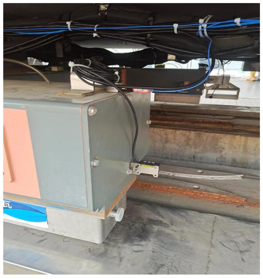
Figure 20.
The levitation height acquisition system.
As shown in Figure 21, the suspension frame vibration state acquisition system collects data on the suspension frame vibration state of an HTS maglev train in real time through a high-precision three-dimensional vibration acceleration sensor. The suspension frame vibration state acquisition system adopts a piezoelectric three-way acceleration sensor with three-way output, which can measure X, Y, and Z directions at the same time. The measuring range in the X, Y, and Z directions is the same ±5g. The impact limit of the acceleration sensor is ±1000 g. The multi-channel constant current source can not only provide the working power required for the normal operation of the three-way acceleration sensor, but also amplify and filter the output signal of the three-way acceleration sensor to provide further processing, such as display, acquisition, and analysis. The output voltage range of the multi-channel constant current source is 0~±5 V.
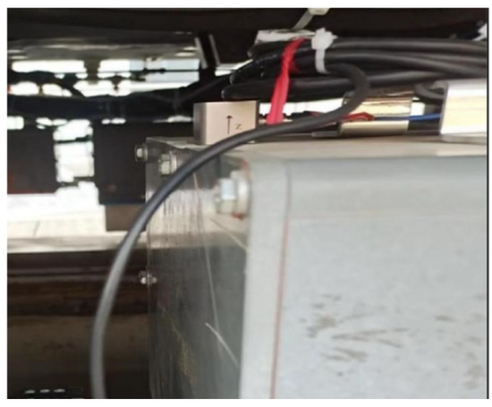
Figure 21.
The suspension frame vibration state acquisition system.
The current high-temperature superconducting maglev train only has 160 m of test track. Limited by the length of the test track, the train runs at a speed of 0.5~4 m/s on the test track to ensure safety. The speed of the train is 0.5, 1, 2, and 4 m/s, and the speed curve is shown in Figures S15–S18. The suspension frame monitoring system online monitors the lateral and vertical vibration acceleration and levitation height of the suspension frame at the left front, right front, left rear, and right rear ends of the suspension frame at different train speeds of 0.5, 1, 2, and 4 m/s, as shown in Figure 22, Figure 23, Figure 24, Figure 25, Figure 26, Figure 27, Figure 28 and Figure 29.
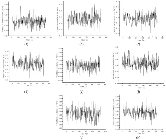
Figure 22.
The maximum running speed of the train is 0.5m/s: (a) The lateral vibration acceleration of the left front acceleration sensor of the suspension frame during the running of the train is −0.13 m/s2 to 0.14 m/s2; (b) The vertical vibration acceleration of the front-left acceleration sensor of the suspension frame during the train running is −0.12 to 0.11 m/s2; (c) The lateral vibration acceleration of the front-right acceleration sensor of the suspension frame during the running of the train is −0.28 to 0.23 m/s2; (d) The vertical vibration acceleration of the front-right acceleration sensor of the suspension frame during the running of the train is −0.17 to 0.19 m/s2; (e) The lateral vibration acceleration of the rear-left acceleration sensor of the suspension frame during the running of the train is −0.18 to 0.14 m/s2; (f) The vertical vibration acceleration of the rear-left acceleration sensor of the suspension frame during the running of the train is −0.25 to 0.25 m/s2; (g) The lateral vibration acceleration of the rear-right acceleration sensor of the suspension frame during the running of the train is −0.01 to 0.16 m/s2; (h) The vibration acceleration of the rear-right acceleration sensor of the suspension frame in the vertical direction during the running of the train is −0.19 to 0.18 m/s2.
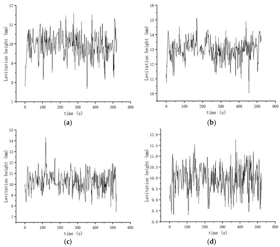
Figure 23.
The maximum speed of the train is 0.5 m/s: (a) The levitation height of the front-left laser displacement sensor of the suspension frame during the running of the train is 7.7−11.5 mm; (b) The levitation height of the laser displacement sensor at the front right of the suspension frame during the running of the train is 10.2–15 mm; (c) The levitation height of the laser displacement sensor at the left rear of the suspension frame during the running of the train is 7.3–14.3 mm; (d) The levitation height of the laser displacement sensor at the right rear of the suspension frame during the train running is 8.3–11.7 mm.
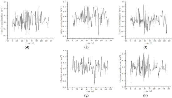
Figure 24.
The maximum running speed of the train is 1 m/s: (a) The lateral vibration acceleration of the front-left acceleration sensor of the suspension frame during the running of the train is −0.12 to 0.08 m/s2; (b) The vertical vibration acceleration of the front-left acceleration sensor of the suspension frame during the running of the train is −0.11 to 0.19 m/s2; (c) The vibration acceleration of the front-right acceleration sensor of the suspension frame in the lateral direction during the running of the train is within the range of −0.16 to 0.14 m/s2; (d) The vertical vibration acceleration of the front-right acceleration sensor of the suspension frame during the running of the train is −0.18 to 0.23 m/s2; (e) The lateral vibration acceleration of the rear-left acceleration sensor of the suspension frame during the running of the train is −0.19 to 0.1 m/s2; (f) The vertical vibration acceleration of the rear-left acceleration sensor of the suspension frame during the running of the train is −0.28 to 0.34 m/s2; (g) The vibration acceleration of the rear-right acceleration sensor of the suspension frame in the lateral direction during the running of the train is −0.08 to 0.16 m/s2; (h) The vertical vibration acceleration of the rear-right acceleration sensor of the suspension frame during the running of the train is −0.24 to 0.21 m/s2.
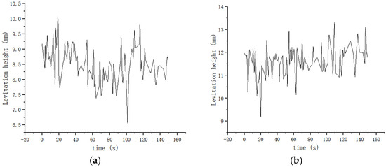
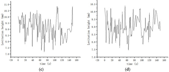
Figure 25.
The maximum speed of the train is 1 m/s: (a) The levitation height of the front-left laser displacement sensor of the suspension frame during the running of the train is 6.6 to 10.1 mm; (b) The levitation height of the laser displacement sensor at the front right of the suspension frame during the running of the train ranges from 9.2 to 13.3 mm; (c) The levitation height of the laser displacement sensor at the rear left of the suspension frame during the running of the train ranges from 7.2 to 10.7 mm; (d) The levitation height of the laser displacement sensor at the right rear of the suspension frame during the train running ranges from 7.4 to 10.3 mm.
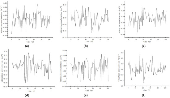
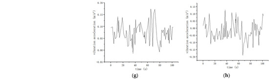
Figure 26.
The maximum running speed of the train is 2 m/s: (a) The vibration acceleration of the front-left acceleration sensor of the suspension frame in the lateral direction during the running of the train is within the range of −0.09 to 0.05 m/s2; (b) The vertical vibration acceleration of the front-left acceleration sensor of the suspension frame during the running of the train is −0.12 to 0.09 m/s2; (c) The vibration acceleration of the front-right acceleration sensor of the suspension frame in the lateral direction during the running of the train is −0.27 to 0.17 m/s2; (d) The vertical vibration acceleration of the front-right acceleration sensor of the suspension frame during the running of the train is −0.21 to 0.18 m/s2; (e) The lateral vibration acceleration of the rear-left acceleration sensor of the suspension frame during the running of the train is −0.16 to 0.12 m/s2; (f) The vertical vibration acceleration of the rear-left acceleration sensor of the suspension frame during the running of the train is −0.25 to 0.27 m/s2; (g) The vibration acceleration of the rear-right acceleration sensor of the suspension frame in the lateral direction during the running of the train is −0.02 to 0.17 m/s2; (h) The vibration acceleration of the rear-right acceleration sensor of the suspension frame in the vertical direction during the running of the train is −0.19 to 0.12 m/s2.
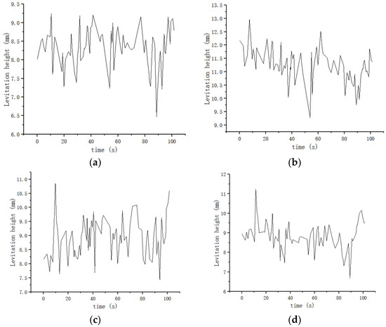
Figure 27.
The maximum speed of the train is 2 m/s: (a) The levitation height of the laser displacement sensor at the front left of the suspension frame during the running of the train ranges from 6.4 to 9.2 mm; (b) The levitation height of the laser displacement sensor at the front right of the suspension frame during the running of the train ranges from 9.2 to 12.8 mm; (c) The levitation height of the laser displacement sensor at the rear left of the suspension frame during the running of the train ranges from 7.3 to 10.8 mm; (d) The levitation height of the laser displacement sensor at the rear right of the suspension frame during the running of the train ranges from 6.7 to 11.3 mm.
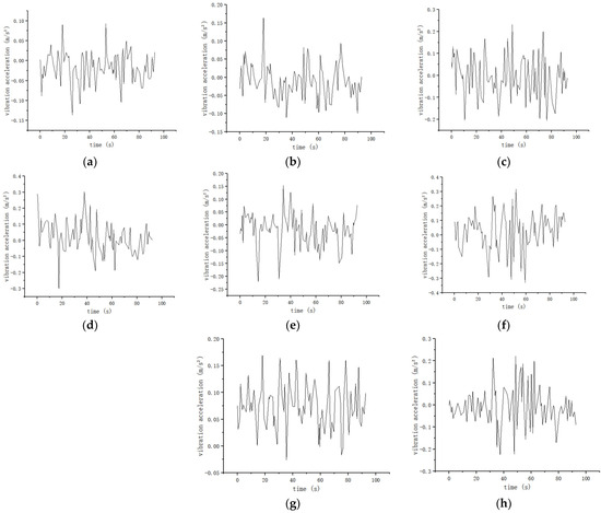
Figure 28.
The maximum running speed of the train is 4 m/s: (a) The lateral vibration acceleration of the front-left acceleration sensor of the suspension frame during the running of the train is −0.13 to 0.09 m/s2; (b) The vertical vibration acceleration of the front-left acceleration sensor of the suspension frame during the running of the train is −0.12 to 0.17 m/s2; (c) The vibration acceleration of the front-right acceleration sensor of the suspension frame in the lateral direction during the running of the train is −0.21 to 0.23 m/s2; (d) The vertical vibration acceleration of the front-right acceleration sensor of the suspension frame during the running of the train is −0.3 to 0.29 m/s2; (e) The lateral vibration acceleration of the rear-left acceleration sensor of the suspension frame during the running of the train is −0.22 to 0.15 m/s2; (f) The vertical vibration acceleration of the rear-left acceleration sensor of the suspension frame during the running of the train is −0.34 to 0.31 m/s2; (g) The vibration acceleration of the rear-right acceleration sensor of the suspension frame in the lateral direction during the running of the train is −0.03 to 0.17 m/s2; (h) The vertical vibration acceleration of the rear-right acceleration sensor of the suspension frame during the running of the train is −0.23 to 0.21 m/s2.
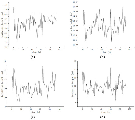
Figure 29.
The maximum speed of the train is 4 m/s: (a) The levitation height of the laser displacement sensor at the front left of the suspension frame during the running of the train ranges from 7.5 to 11.2 mm; (b) The levitation height of the laser displacement sensor at the front right of the suspension frame during the running of the train ranges from 11.2 to 14.8 mm; (c) The levitation height of the laser displacement sensor at the rear left of the suspension frame during the running of the train ranges from 8.6 to 12.3 mm; (d) The levitation height of the laser displacement sensor at the rear right of the suspension frame during the running of the train ranges from 8.2 to 12.1 mm.
According to the suspension frame monitoring system, the relevant data on the lateral and vertical vibration acceleration and levitation height of the suspension frame at the front-left, front-right, rear-left, and rear-right ends of the suspension frame are monitored in different train speeds of 0.5, 1, 2 and 4 m/s. As shown in Table 4, the levitation height is limited to between 6.4 and 15 mm, the risk of collision with the track is negligible, and the train can run safely. As shown in Table 5 and Table 6, the maximum vertical acceleration of the suspension frame is less than 0.34 m/s2, and the maximum lateral acceleration is less than 0.28 m/s2, which is smaller than 0.13 g in the “High Speed Railway Design Code” [27] and 0.1 g in the “Interim Provisions for the Design of Beijing-Shanghai High Speed Railway” [28]. The results show the advantages in terms of safety and stationarity for the HTS maglev train.
Table 4.
Levitation height at four ends of the suspension frame at different speeds.
Table 5.
Vertical vibration acceleration at four ends of the suspension frame at different speeds.
Table 6.
Lateral vibration acceleration at four ends of the suspension frame at different speeds.
4. Conclusions
In this paper, the suspension frame is simulated and analyzed to simulate the real load situation of a maglev train. According to the strength analysis and calculation of AW3 ultimate working conditions, the stress distribution of the suspension frame is similar under parking (suspension state), traction working condition 3, traction working condition 4, traction working condition 5, traction working condition 8, and braking working condition. The maximum stress position of the suspension frame is concentrated at the connection of the reaction plate and the dewar beam, but the stress value does not exceed the yield limit value of the material. The maximum stress of the suspension frame during parking (supported by the supporting wheel) is concentrated at the supporting wheel, and the stress value does not exceed the yield limit value of the material. The deformation value of the dewar beam is very small, and the stiffness of the dewar beam is large enough. The maximum stress of the traction seat is far less than the allowable stress of the material, the strength check is qualified, and the deformation is small, which can meet the use requirements. The suspension frame of an HTS maglev train can bear corresponding loads under different working conditions, and its strength and stiffness meet the requirements of use, which is safe and reliable.
In the levitation force model of an HTS maglev train, the levitation height will directly affect the levitation force. At the same time, the levitation force will directly affect the vibration acceleration of the suspension frame. It is necessary to monitor the vibration acceleration and the levitation height of the suspension frame. Through the use of a suspension frame monitoring system, the lateral and vertical vibration acceleration and levitation height of the suspension frame are monitored at different train speeds. The maximum value of vibration acceleration and the fluctuation range of levitation height are within the safe range. It is verified that the simulation analysis of the suspension frame of an HTS maglev train is correct, the suspension frame is safe and the train can run safely.
Supplementary Materials
The following supporting information can be downloaded at: https://www.mdpi.com/article/10.3390/machines11060607/s1, Figure S1: Deformation diagram of suspension frame under parking (suspension) state; Figure S2: Deformation diagram of suspension frame when the support surface is fixed under parking (suspension) state; Figure S3: Deformation diagram of suspension frame under parking (support wheel support); Figure S4: Deformation diagram of suspension frame under traction condition (condition 3); Figure S5: Deformation diagram of suspension frame when the lower support surface is fixed; Figure S6: Deformation diagram of suspension frame under traction condition (condition 4); Figure S7: Deformation of suspension frame when the lower support surface is fixed under traction condition (condition 4); Figure S8: Deformation of suspension frame under traction condition (condition 5); Figure S9: Deformation diagram of suspension frame when the lower support surface is fixed under traction condition (condition 5); Figure S10: Deformation diagram of suspension frame under traction condition (condition 8); Figure S11: Deformation diagram of suspension frame when the lower support surface is fixed under traction condition (condition 8); Figure S12: The deformation of suspension frame under braking condition; Figure S13: Deformation of suspension frame when the support surface is fixed under braking conditions; Figure S14: Deformation of traction seat; Figure S15: The maximum speed of the train is 0.5m/s, and the schematic diagram of the speed during the train running; Figure S16: The maximum speed of the train is 1m/s, and the schematic diagram of the speed during the train running; Figure S17: The maximum speed of the train is 2m/s, and the schematic diagram of the speed of the train during running; Figure S18: The maximum speed of the train is 4m/s, and the schematic diagram of the speed during the train running.
Author Contributions
Methodology, investigation, data curation, analysis, writing-original draft, writing- review and editing, Y.W.; Editing, supervision, H.G. All authors have read and agreed to the published version of the manuscript.
Funding
This research received no external funding.
Data Availability Statement
Not applicable.
Conflicts of Interest
The authors declare no conflict of interest in this article.
References
- Brandt, E.H. Levitation in Physics. Science 1989, 243, 349–355. [Google Scholar] [CrossRef] [PubMed]
- Moon, F.C. Superconducting Levitation: Applications to Bearings and Magnetic Transportation; Wiley: Hoboken, NJ, USA, 1994. [Google Scholar]
- Lee, H.-W.; Kim, K.-C.; Lee, J. Review of maglev train technologies. IEEE Trans. Magn. 2006, 42, 1917–1925. [Google Scholar]
- Zeng, R.; Murashov, V.; Beales, T.; Liu, H.; Dou, S. High temperature superconducting magnetic levitation train. Appl. Supercond. 1997, 5, 201–204. [Google Scholar] [CrossRef]
- Sotelo, G.G.; de Andrade, R.; Dias, D.H.N.; Ferreira, A.C.; Costa, F.; Machado, O.J.; de Oliveira, R.A.H.; Santos, M.D.A.; Stephan, R.M. Tests with one module of the Brazilian Maglev-Cobra vehicle. IEEE Trans. Appl. Supercond. 2013, 23, 3601204. [Google Scholar] [CrossRef]
- Schultz, L.; de Haas, O.; Verges, P.; Beyer, C.; Rohlig, S.; Olsen, H.; Kuhn, L.; Berger, D.; Noteboom, U.; Funk, U. Superconductively Levitated Transport System—The SupraTrans Project. IEEE Trans. Appl. Supercond. 2005, 15, 2301–2305. [Google Scholar] [CrossRef]
- Yang, W.; Liu, Y.; Wen, Z.; Chen, X.; Duan, Y. Dynamic Force Properties of a High Temperature Superconducting Maglev Test Vehicle. IEEE Trans. Appl. Supercond. 2008, 18, 799–802. [Google Scholar] [CrossRef]
- Ma, K.B.; Postrekhin, Y.; Chu, W.K. Superconductor and magnet levitation devices. Rev. Sci. Instrum. 2003, 74, 4989–5017. [Google Scholar] [CrossRef]
- Mulcahy, T.M.; Hull, J.R.; Uherka, K.L.; Abboud, R.G.; Juna, J.J. Test result of 2-kWh flywheel using passive PM and HTS bear-ing. IEEE Trans. Appl. Supercond. 2001, 11, 1729–1732. [Google Scholar] [CrossRef]
- Yang, W.; Ji, Y.; Yu, L.; Liu, X.; Long, J.; Liu, Z.; Song, D. Low frequency rotational loss in a high-temperature superconducting bearing and its application in micro-thrust measure-ment for space propulsion. Supercond. Sci. Technol. 2020, 33, 014001. [Google Scholar] [CrossRef]
- Mattos, L.S.; Rodriguez, E.; Costa, F.; Sotelo, G.G.; De Andrade, R.; Stephan, R.M. MagLev-Cobra operational tests. IEEE Trans. Appl. Supercond. 2016, 26, 3600704. [Google Scholar] [CrossRef]
- Hellman, F.; Gyorgy, E.M.; Johnson, D.W.; O’bryan, H.M.; Sherwood, R.C. Levitation of a magnet over a flat type II superconduct-tor. J. Appl. Phys. 1988, 63, 447–450. [Google Scholar] [CrossRef]
- Peters, P.N.; Sisk, R.C.; Urban, E.W.; Huang, C.Y.; Wu, M.K. Observation of enhanced properties in samples of silver oxide doped YBa2Cu3Ox. Appl. Phys. Lett. 1988, 52, 2066–2067. [Google Scholar] [CrossRef]
- Moon, F.C.; Yanoviak, M.M.; Ware, R. Hysteretic levitation forces in superconducting ceram-ics. Appl. Phys. Lett. 1988, 52, 1534–1536. [Google Scholar] [CrossRef]
- Hull, J.R.; Cansiz, A. Vertical and lateral forces between a permanent mag-net and a high-temperature superconductor. J. Appl. Phys. 1999, 86, 6396–6404. [Google Scholar] [CrossRef]
- Hikihara, T.; Moon, F.C. Chaotic levitated motion of a magnet supported by superconductor. Phys. Lett. A 1994, 191, 279–284. [Google Scholar] [CrossRef]
- Li, J.; Deng, Z.; Xia, C.; Gou, Y.; Wang, C.; Zheng, J. Subharmonic resonance in magnetic levitation of the high-temperature superconducting bulks YBa2Cu3O7-x under harmonic excitation. IEEE Trans. Appl. Supercond. 2019, 29, 3600908. [Google Scholar]
- Li, J.; Li, H.; Zheng, J.; Zheng, B.; Huang, H.; Deng, Z. Nonlinear vibration behaviors of high-Tc superconducting bulks in an applied permanent magnetic array field. J. Appl. Phys. 2017, 121, 243901. [Google Scholar] [CrossRef]
- Sugiura, T.; Tashiro, M.; Uematsu, Y.; Yoshizawa, M. Mechanical stability of a high-Tc superconduct ing levitation system. IEEE Trans. Appl. Supercond 1997, 7, 386–389. [Google Scholar] [CrossRef]
- Suda, T.; Kobayashi, S.; Sugiura, T. Subharmonic Resonance of a Rotor Supported by a High-Tc Superconductor. IEEE Trans. Appl. Supercond. 2010, 21, 1493–1496. [Google Scholar]
- Li, J.; Zheng, J.; Huang, H.; Li, Y.; Li, H.; Deng, Z. Motion stability of the magnetic levitation and suspension with YBa2Cu3O7-x high-Tc superconducting bulks and NdFeB magnets. J. Appl. Phys. 2017, 122, 153902. [Google Scholar] [CrossRef]
- Zhang, M.; Sun, G.; Liu, P.; Yan, Y.; Yang, X.; Yan, Y.; Liu, L. Research on Force Characteristics and Running Performance of Novel Type High-Temperature Superconductor Magnetic Levitation Vehicle. J. Supercond. Nov. Magn. 2022, 35, 635–646. [Google Scholar] [CrossRef]
- Li, Y.; Zhou, D.; Cui, P.; Yu, P.; Chen, Q.; Wang, L.; Li, J. Dynamic Performance Optimization of Electromagnetic Levitation System Considering Sensor Position. IEEE Access 2020, 8, 29446–29455. [Google Scholar] [CrossRef]
- Xu, Y.; Long, Z.; Zhao, Z.; Zhai, M.; Wang, Z. Real-Time Stability Performance Monitoring and Evaluation of Maglev Trains’ Levitation System: A Data-Driven Approach. IEEE Trans. Intell. Transp. Syst. 2020, 23, 1912–1923. [Google Scholar] [CrossRef]
- Li, H.; Deng, Z.; Jin, L.; Li, J.; Li, Y.; Zheng, J. Lateral motion stability of high-temperature superconducting maglev systems derived from a nonlinear guidance force hysteretic model. Supercond. Sci. Technol. 2018, 31, 075010. [Google Scholar] [CrossRef]
- Li, H.; Deng, Z.; Ke, Z.; Yu, J.; Ma, S.; Zheng, J. Curve negotiation performance of high-temperature superconducting maglev based on guid-ance force experiments and dynamic simulations. IEEE Trans. Appl. Supercond. 2020, 30, 3600311. [Google Scholar]
- TB10621-2014; High Speed Railway Design Code. China Railway Press: Beijing, China, 2014.
- Ministry of Railways of China. Interim Provisions for the Design of Beijing-Shanghai High Speed Railway; China Railway Press: Beijing, China, 2003.


Disclaimer/Publisher’s Note: The statements, opinions and data contained in all publications are solely those of the individual author(s) and contributor(s) and not of MDPI and/or the editor(s). MDPI and/or the editor(s) disclaim responsibility for any injury to people or property resulting from any ideas, methods, instructions or products referred to in the content. |
© 2023 by the authors. Licensee MDPI, Basel, Switzerland. This article is an open access article distributed under the terms and conditions of the Creative Commons Attribution (CC BY) license (https://creativecommons.org/licenses/by/4.0/).