
Research on Swing Model and Fuzzy Anti Swing Control Technology of Bridge Crane


Abstract
1. Introduction
2. Load Analysis of the Bridge Cranes under Typical Operating Conditions
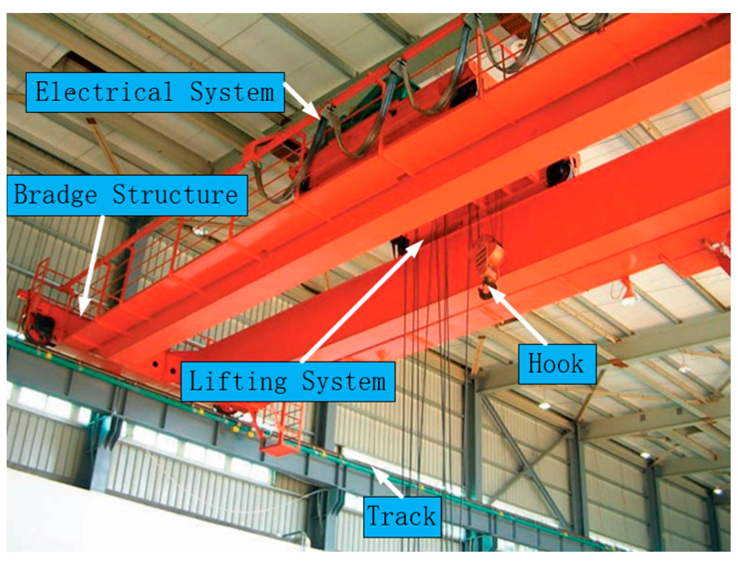
2.1. The Structure of the Bridge Crane
- (1)
- Bridge structure: bears the weight of the lifting trolley, composed of end beams, main beams, railings, walking platforms, tracks, and cabs.
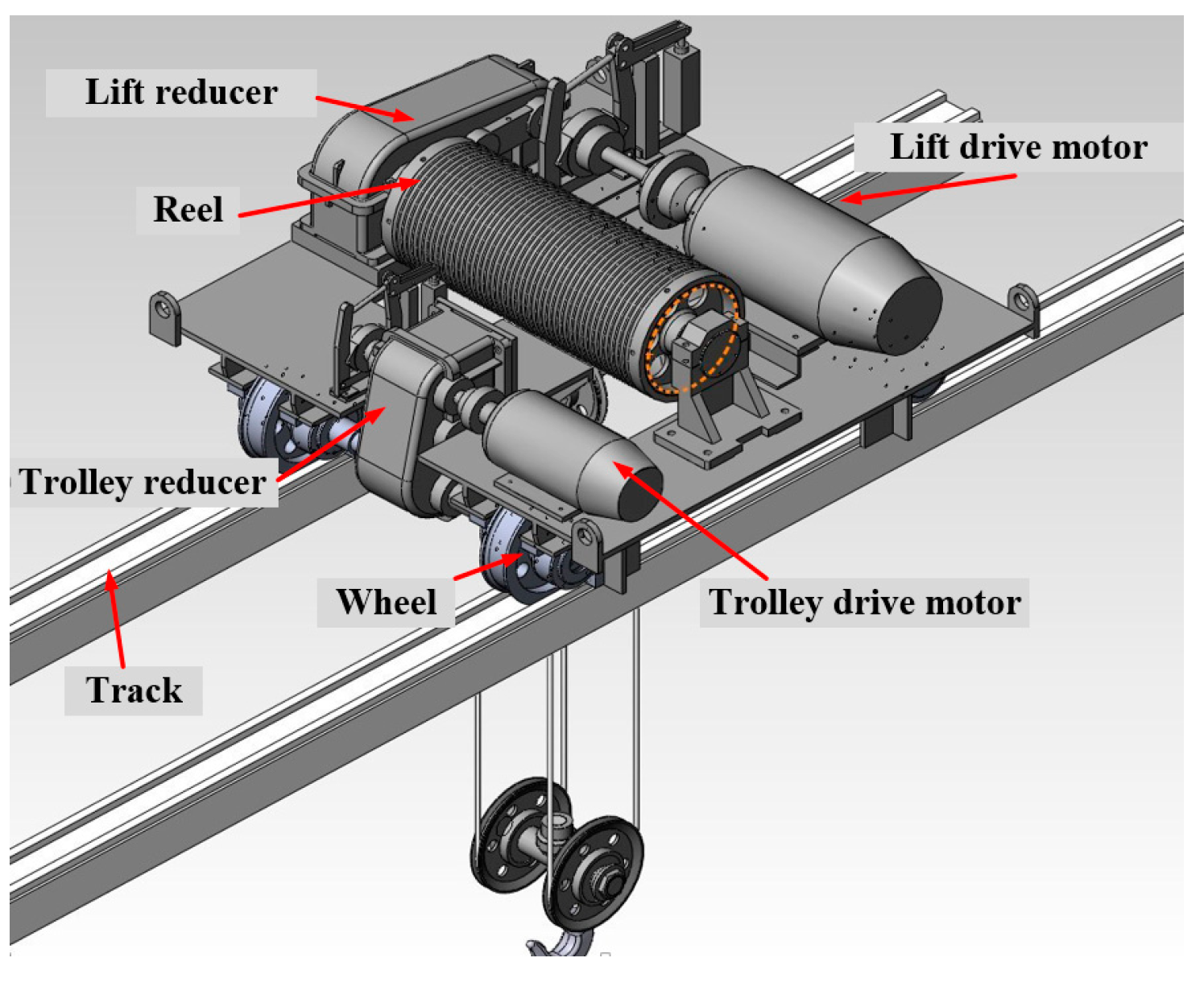
- (2)
- Operating mechanism: The operating mechanism is subdivided into a large trolley operating mechanism and a small trolley operating mechanism, which drives the wheels of the crane and the trolley, respectively, to run along their respective tracks to complete the specified movement (Figure 2 is the mechanism diagram of the trolley).
- (3)
- Lifting mechanism: The function of the lifting mechanism is to realize the lifting movement of materials, which is mainly composed of a motor, pulley block, steel wire rope, braking device, and other corresponding safety devices.
- (4)
- Electrical device: The electrical system of the bridge crane includes electrical equipment and electrical wiring. It is composed of a power supply device, protection box, lighting equipment, electrical circuit, electrical main circuit, lighting signal circuit, control circuit, etc.
2.2. The Workflow of the Bridge Crane
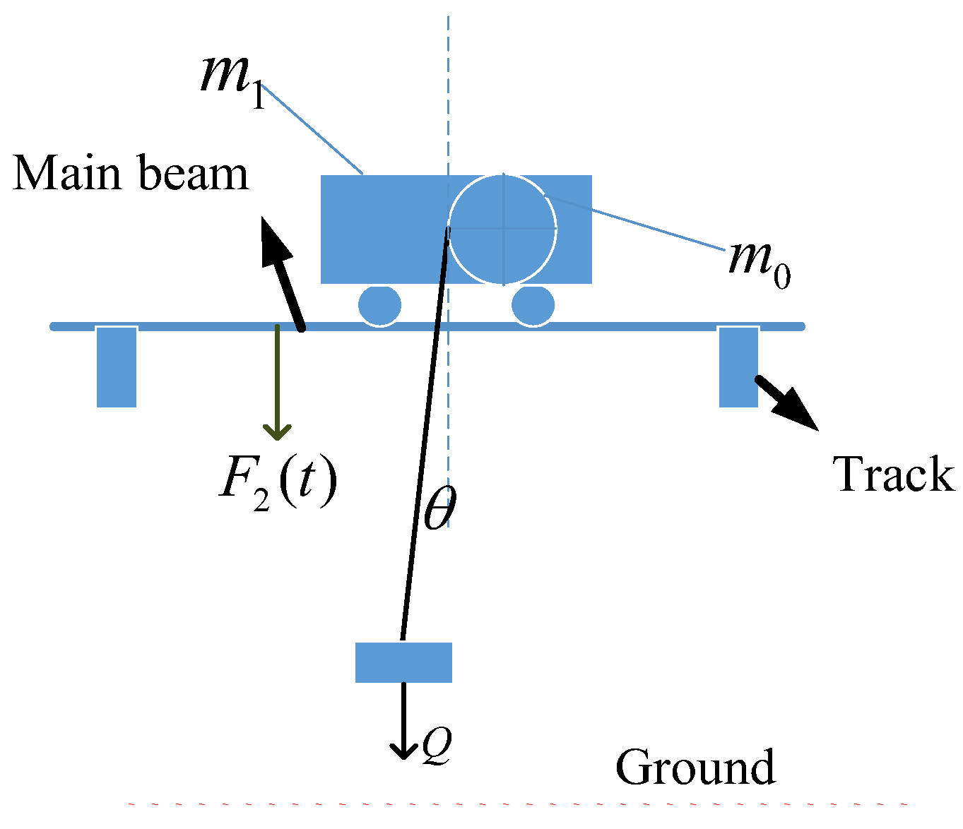
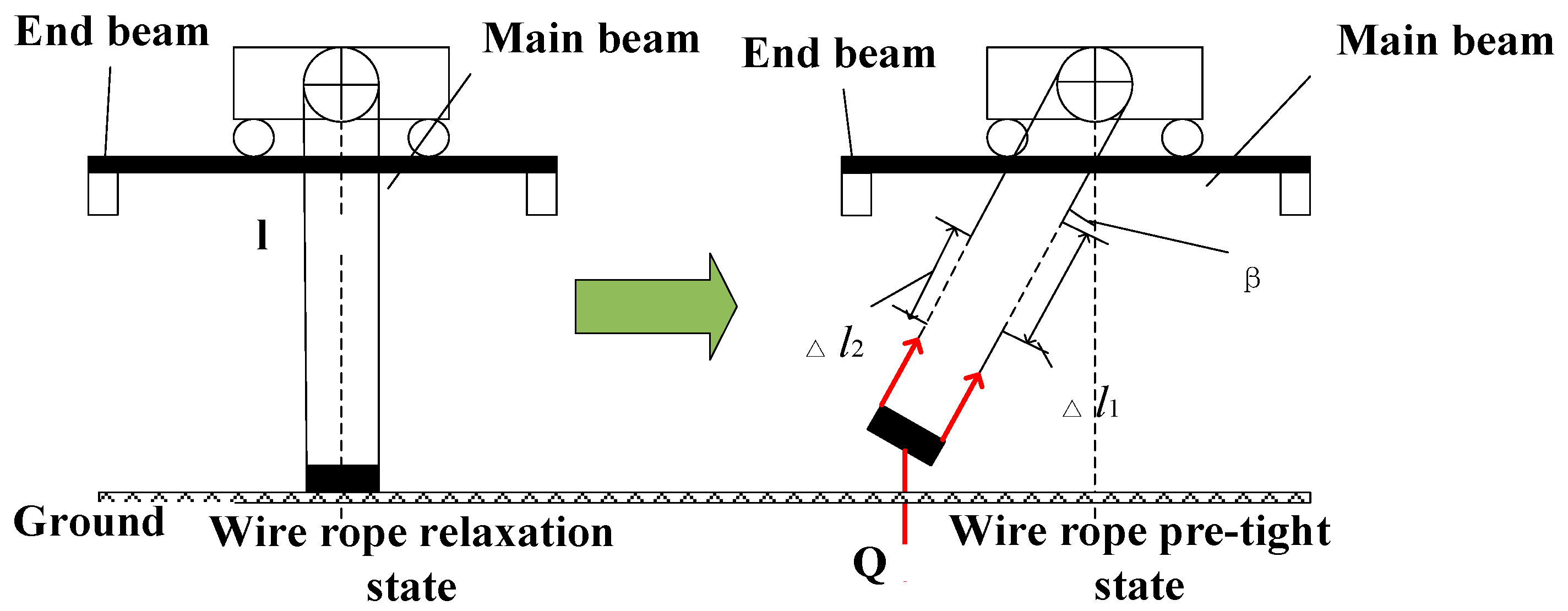
2.2.1. Load Analysis of Crane during Lifting Stage
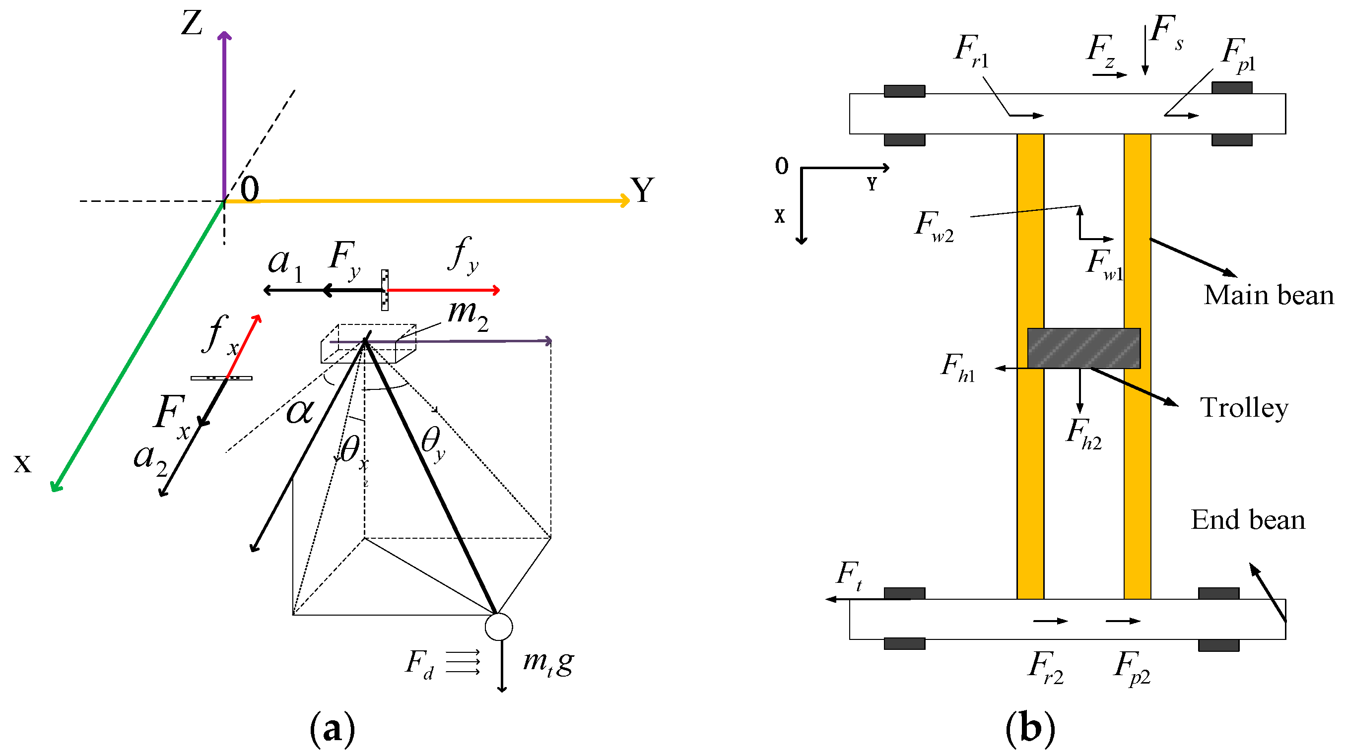
2.2.2. Load Analysis of Large (Small) Trolley of the Cranes during Acceleration
- (1)
- Horizontal inertia
- (2)
- Total running resistance
- (3)
- Horizontal lateral force when the crane moves obliquely
- (1)
- Wind load of the -direction ()
3. Dynamic Analysis and Mathematical Model Construction of Crane Motion System
3.1. Kinematics Analysis of Crane in a Working Cycle
- (1)
- The movement processes of the big and small trolleys are independent of each other.
- (2)
- The elastic deformation of the bridge crane structure is ignored.
- (3)
- The friction between the wheel of the trolley and the track of the trolley is the ideal rolling friction, and the friction coefficient is constant.
- (4)
- The steel rope is regarded as a quality sling, and the friction between it and the pulley and drum of the trolley hoisting mechanism is ignored.
- (5)
- The wire rope is ideally wound on the drum groove and pulley and does not slip during lifting or lowering.
- (6)
- The additional resistance caused by the two tracks being not on the same plane is incorporated into the wheel rolling friction.
- (7)
- and are completely affected by the output of the inverter, and some non-linear factors, such as reducer and trolley motor, are ignored
3.2. Construction of the Mathematical Model of the Swing Angle in the -Direction during the Work Process of the Crane
- (1)
- The initial swing angle of the lifting weight during the lifting phase
- (2)
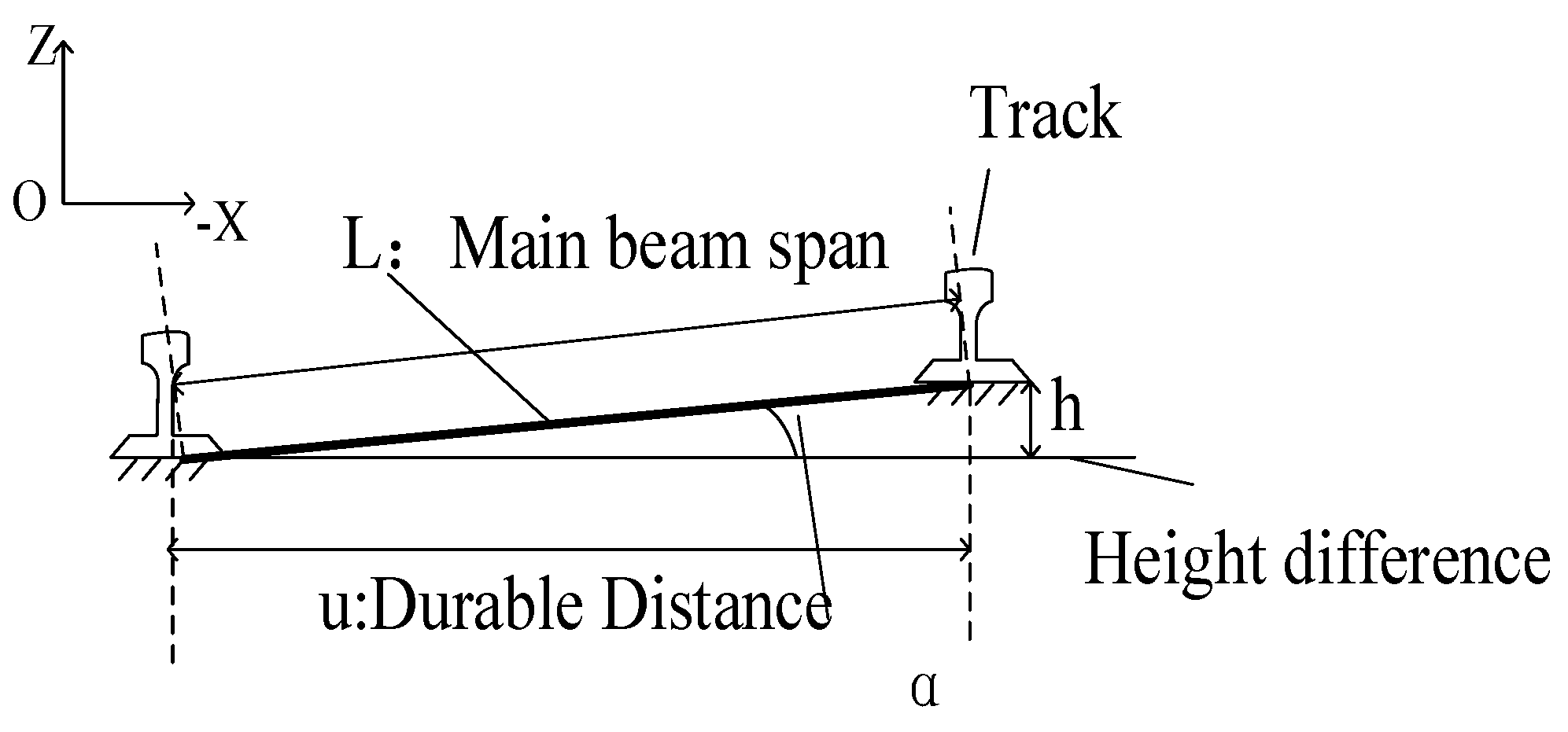
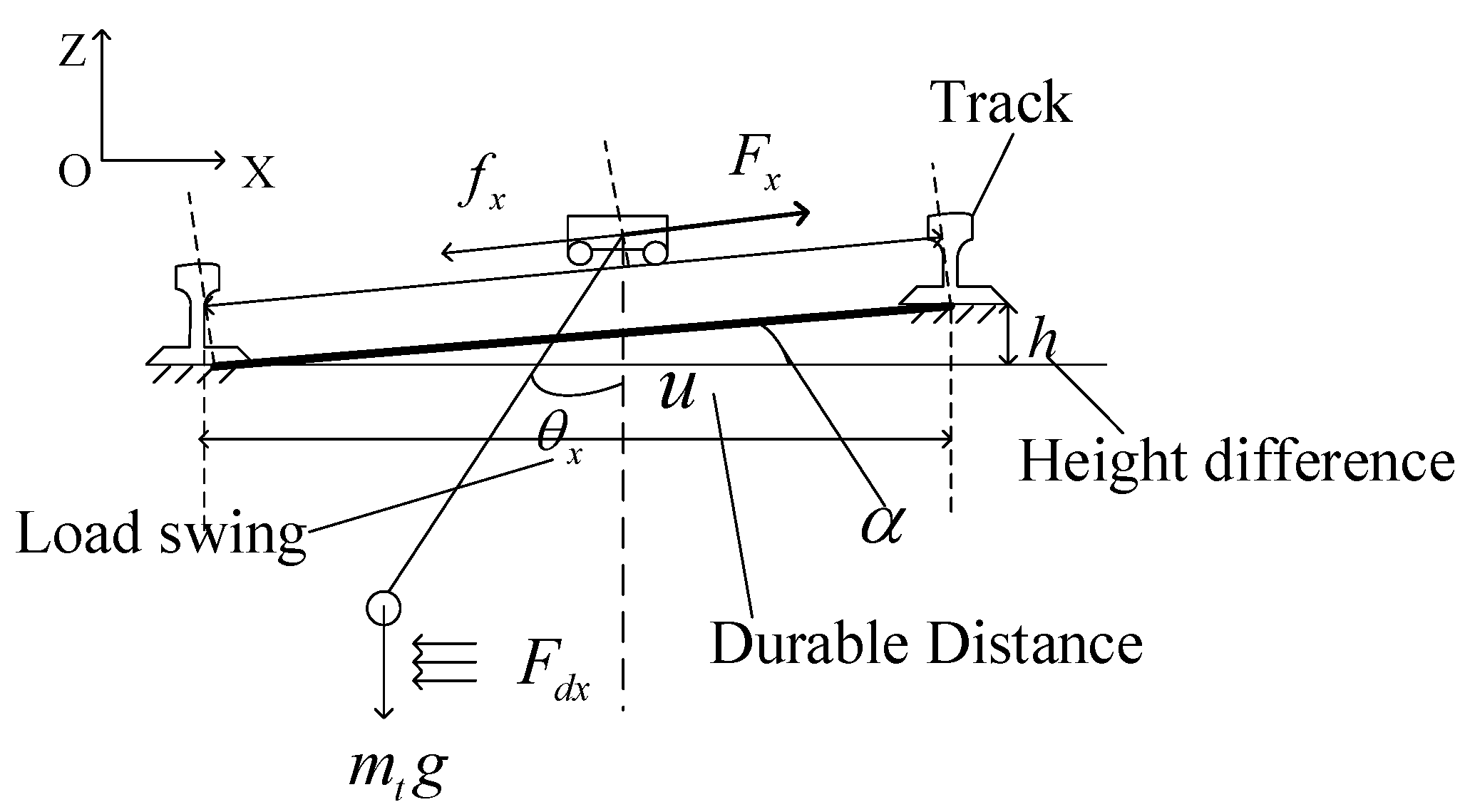
- When the large trolley is moving in the -direction
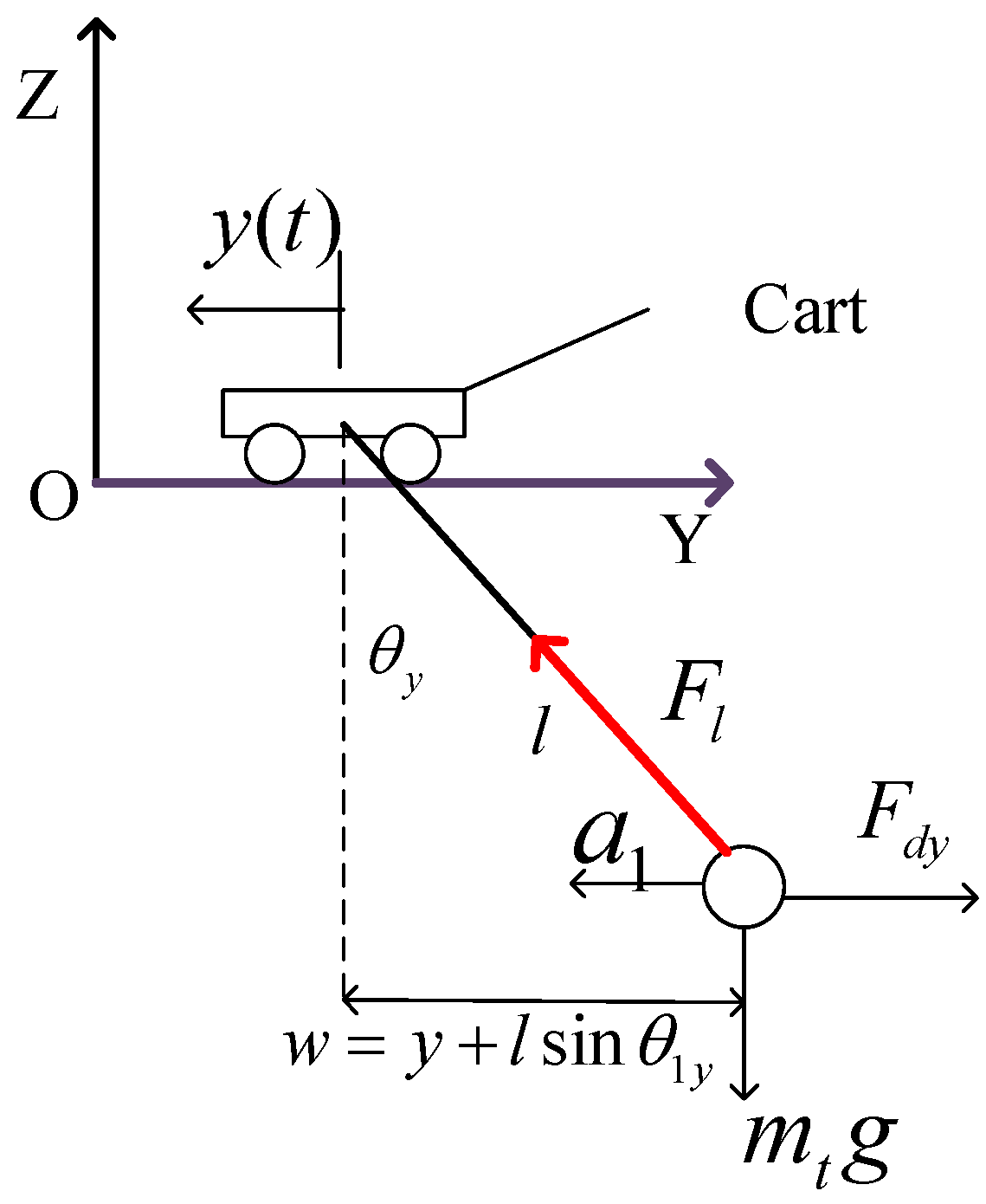
3.3. Construction of the Mathematical Model of the Swing Angle in the -Direction during the Work Process of the Crane
4. Three-Dimensional Simulation Model of Swing Angle of Lifting Weight
5. Analysis of Influencing Factors of Swing Angle of Lifting Weight
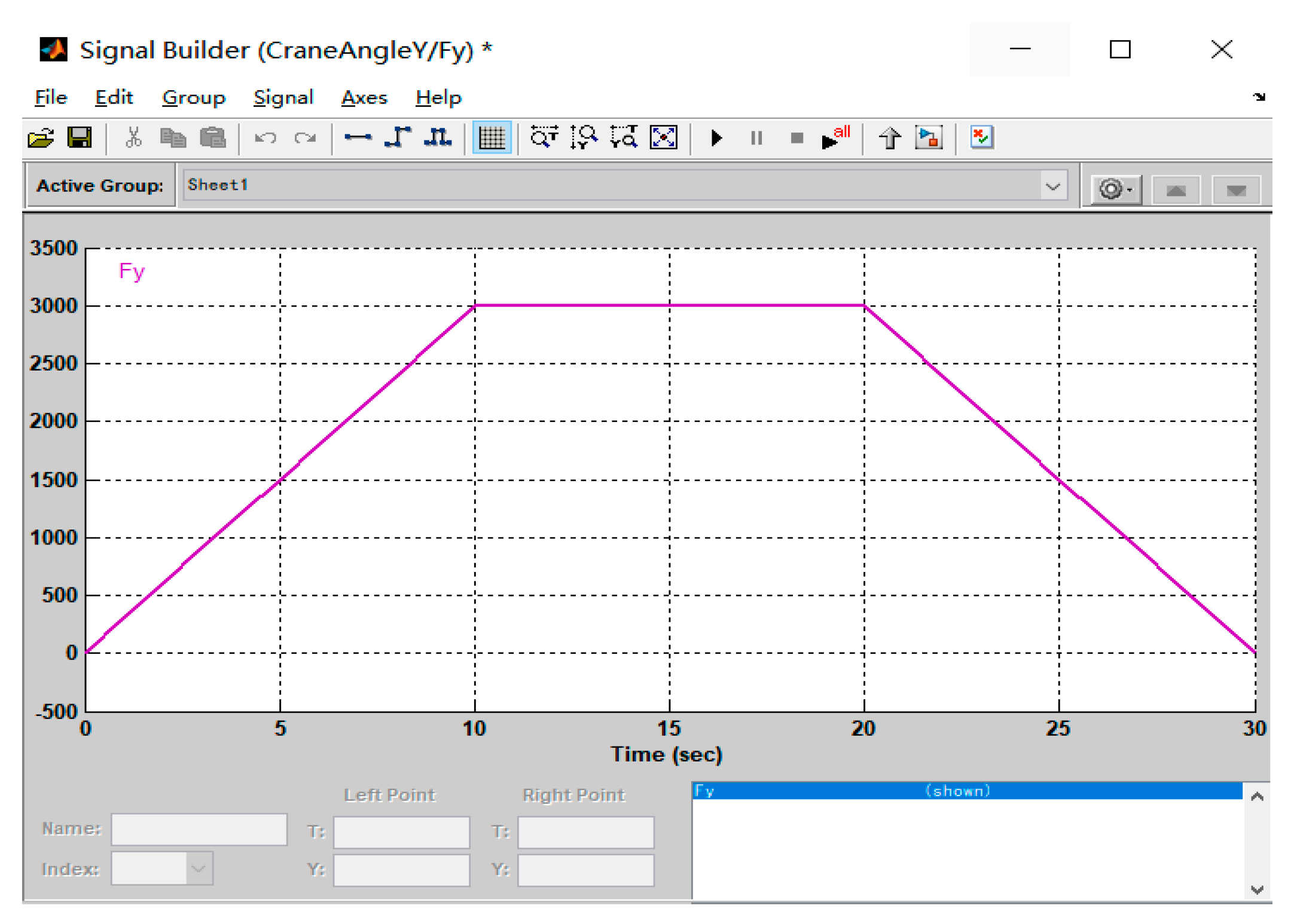
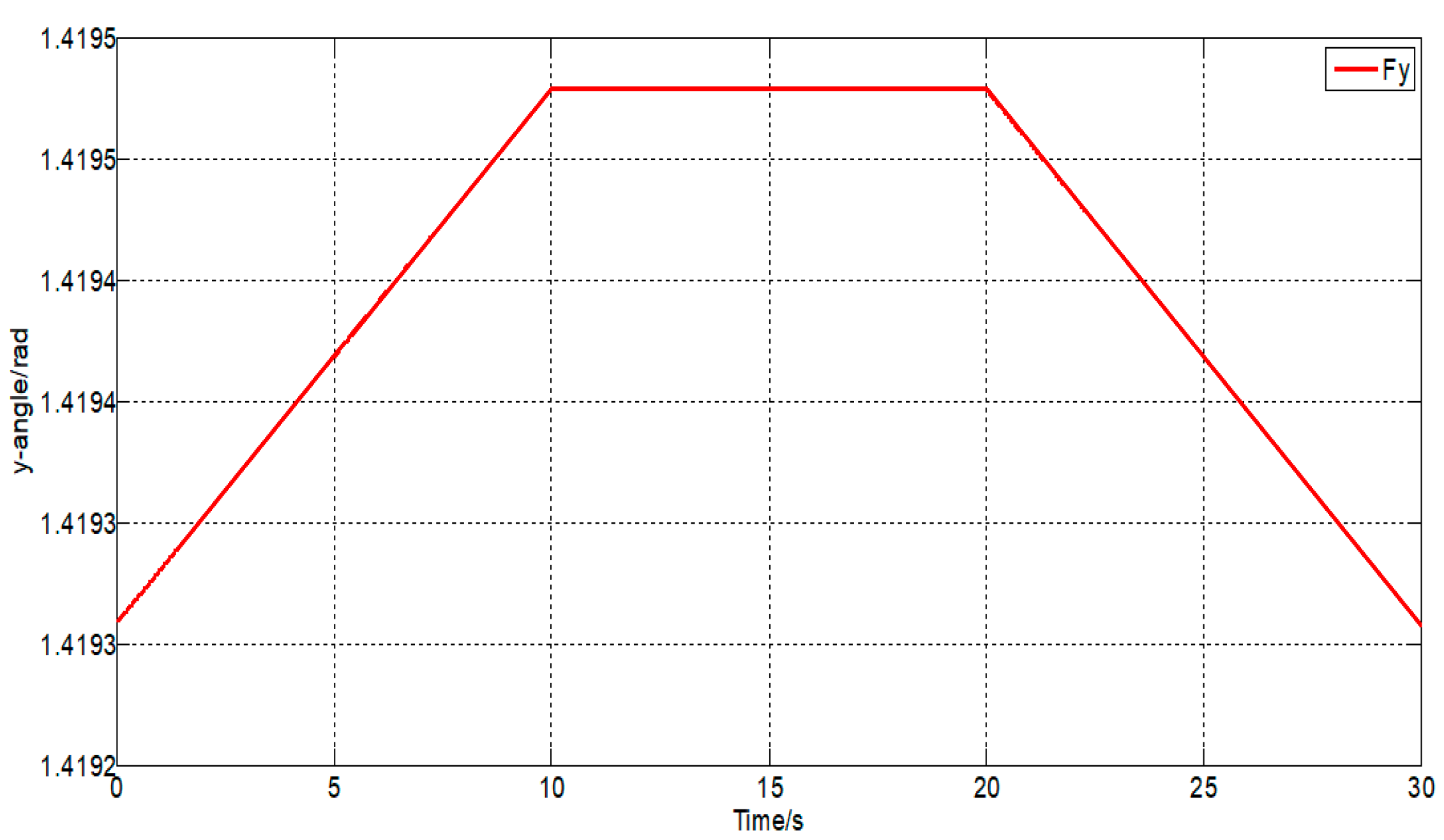
5.1. The Influence of the Driving Force on the Swing Angle
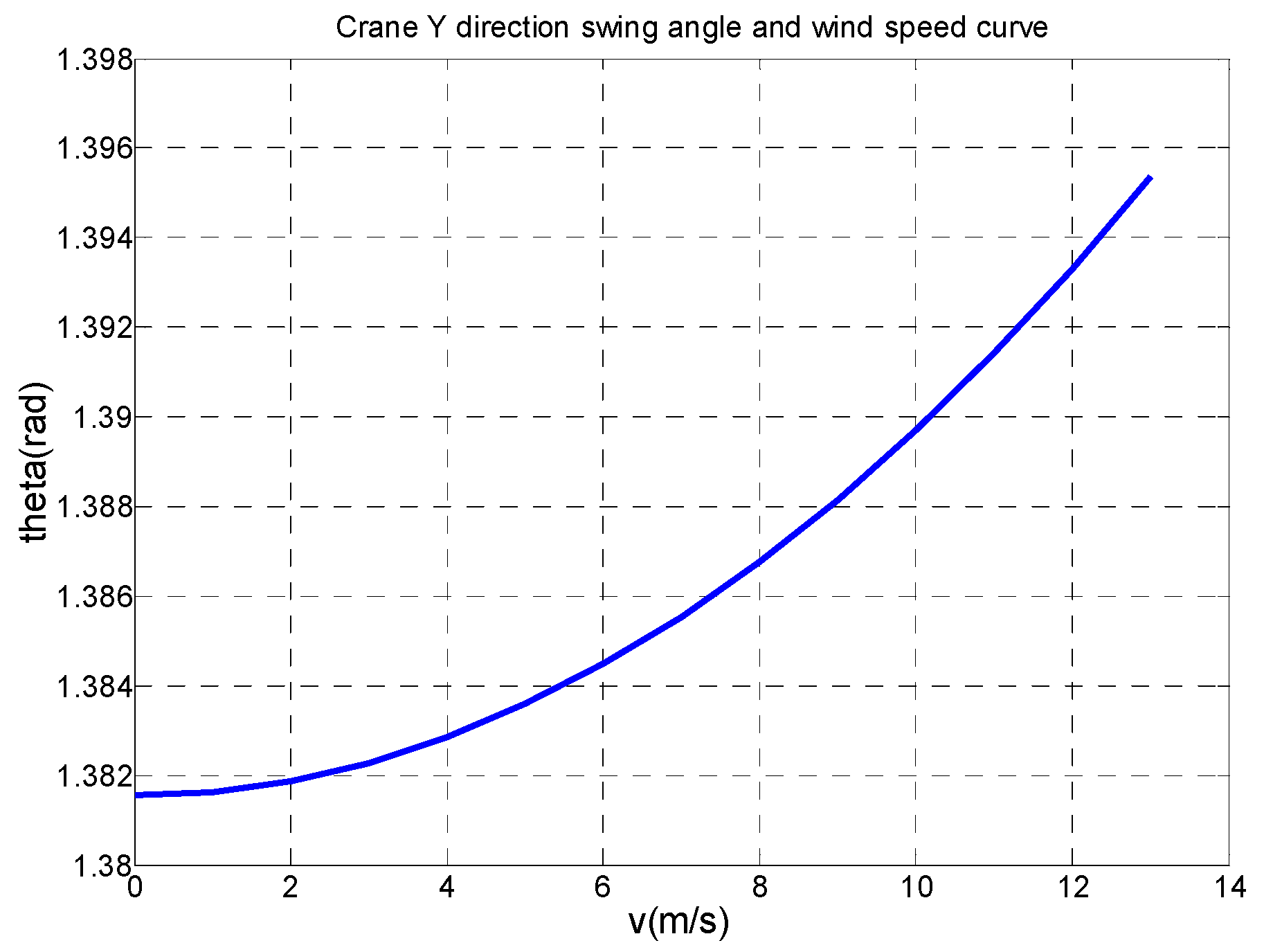
5.2. The Influence of Wind Load on Swing Angle
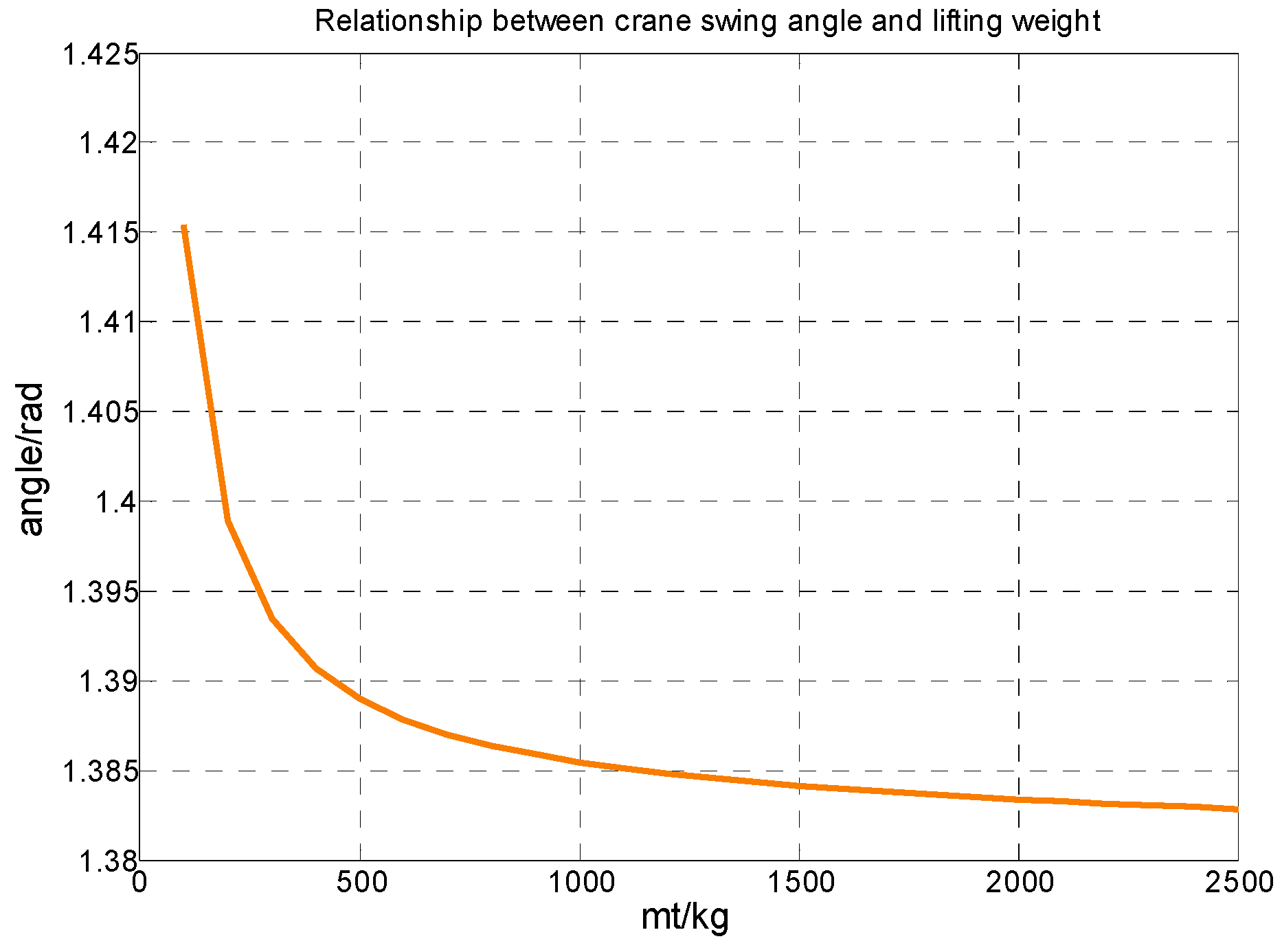
5.3. The Influence of Lifting Weight Quality on Swing Angle
6. Research on Anti Sway Control Technology of Bridge Crane
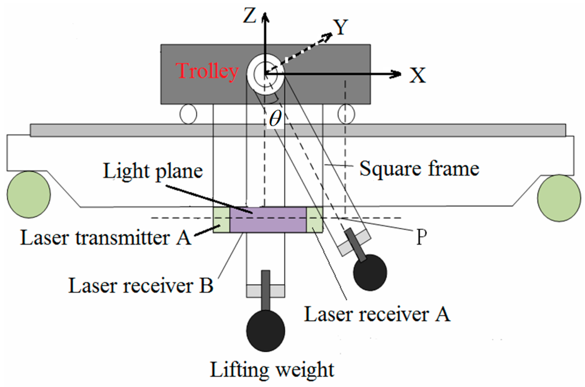
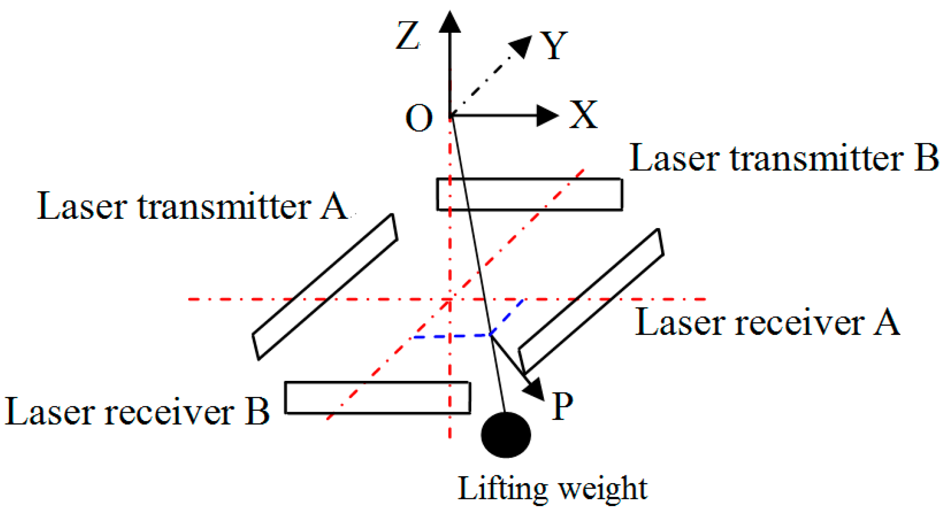
6.1. Swing Angle Detection during Crane Operation
6.2. Design of Anti-Sway Controller for Bridge Crane
6.2.1. Design of Conventional PID Anti-Sway Controller for Bridge Crane
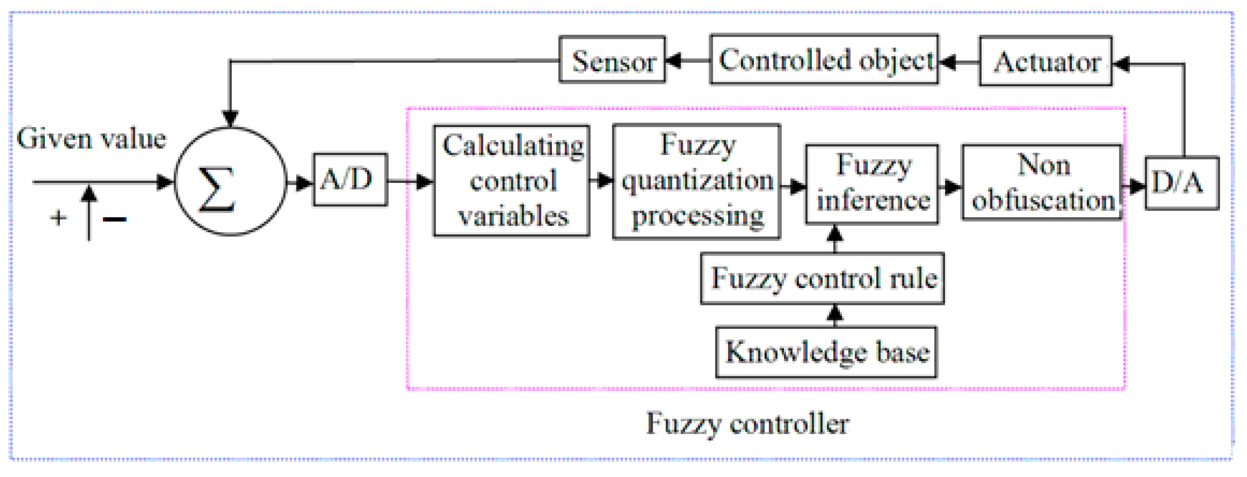
6.2.2. Design of Fuzzy Anti-Sway Controller for Bridge Crane
- (1)
- Determination of basic parameters of the fuzzy controller:
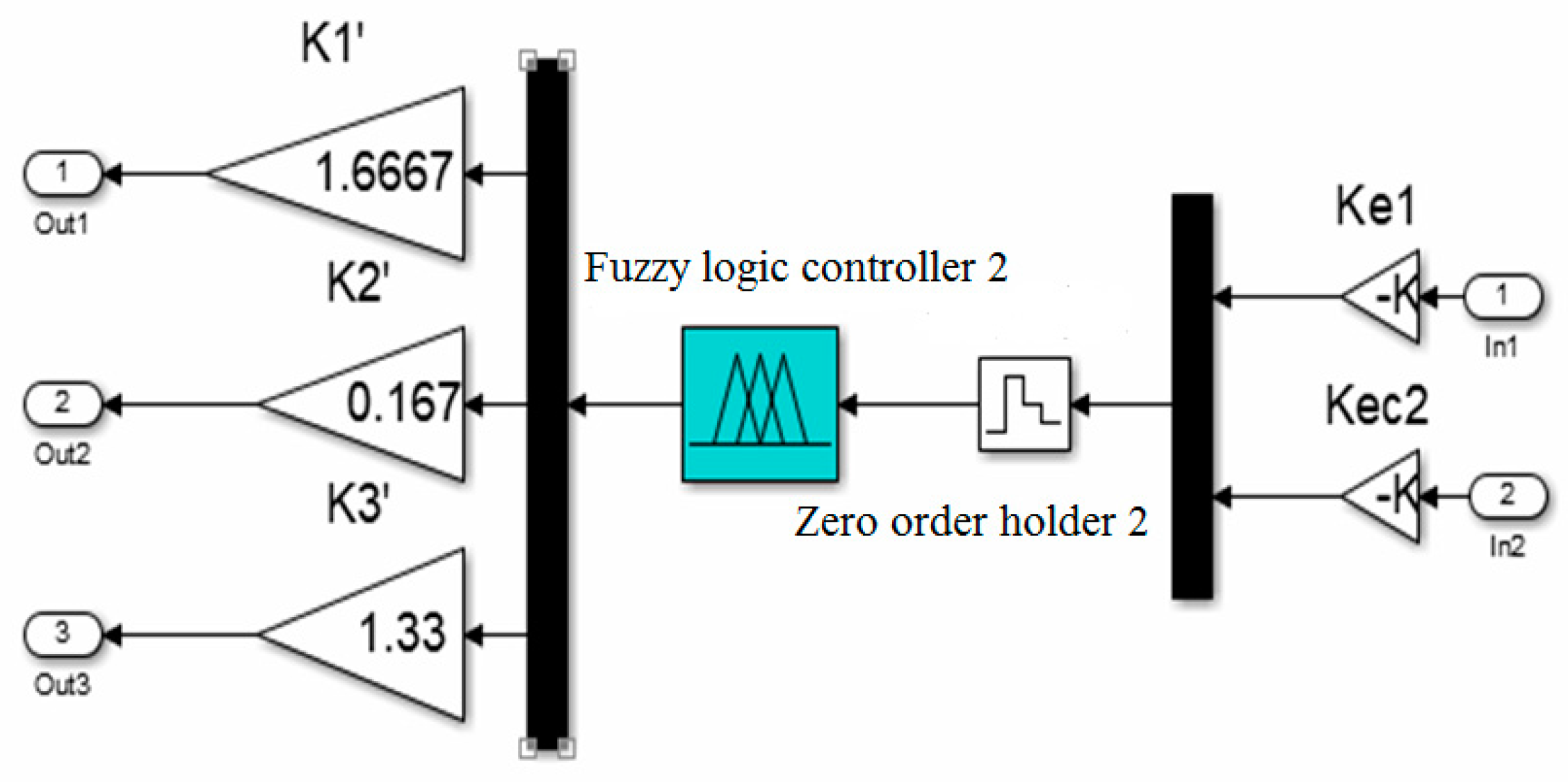
- (2)
- Membership function and fuzzy rules of the anti-sway fuzzy controller
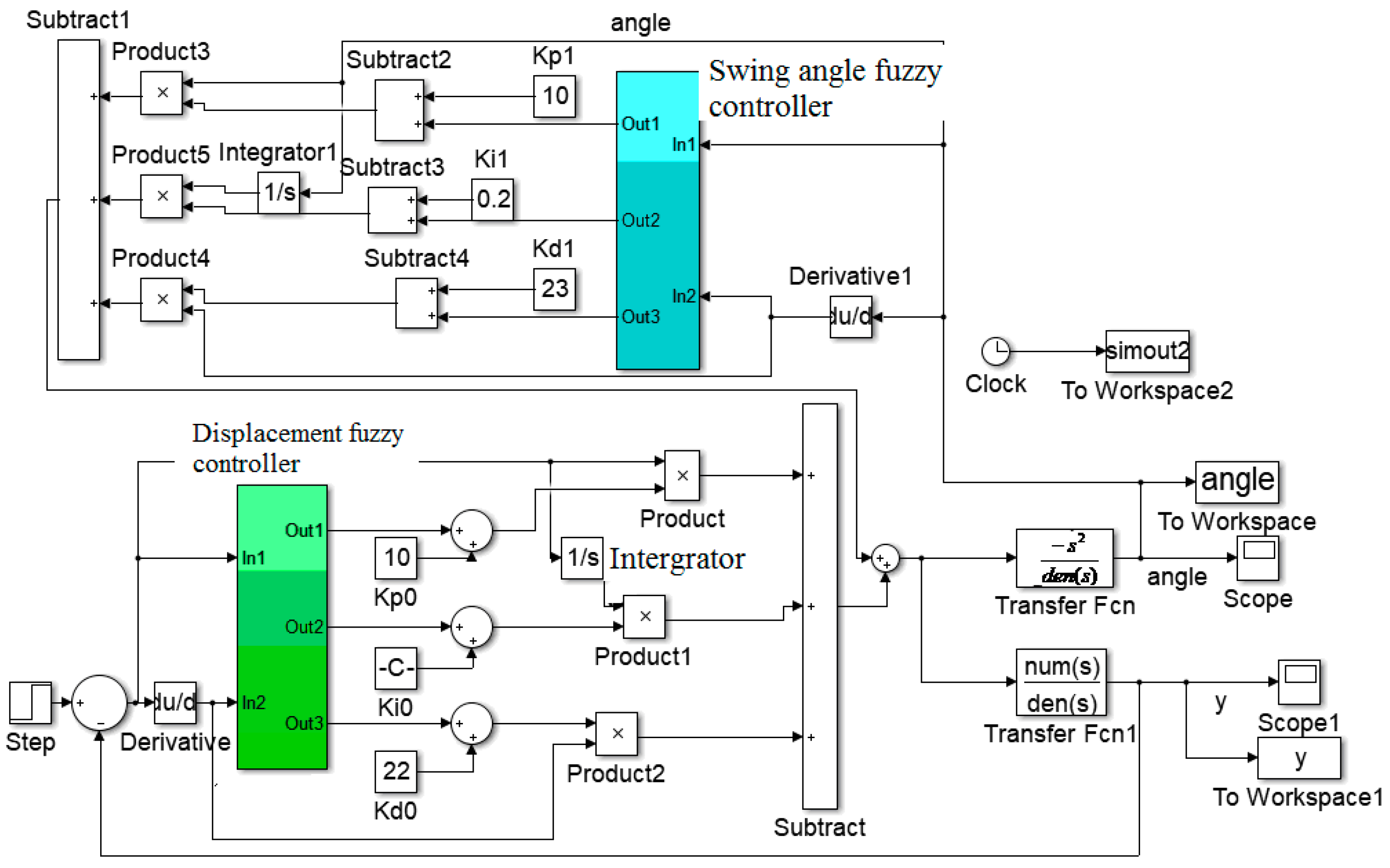
6.3. Simulation of a Fuzzy PID Control System for the Anti-Sway of the Bridge Crane
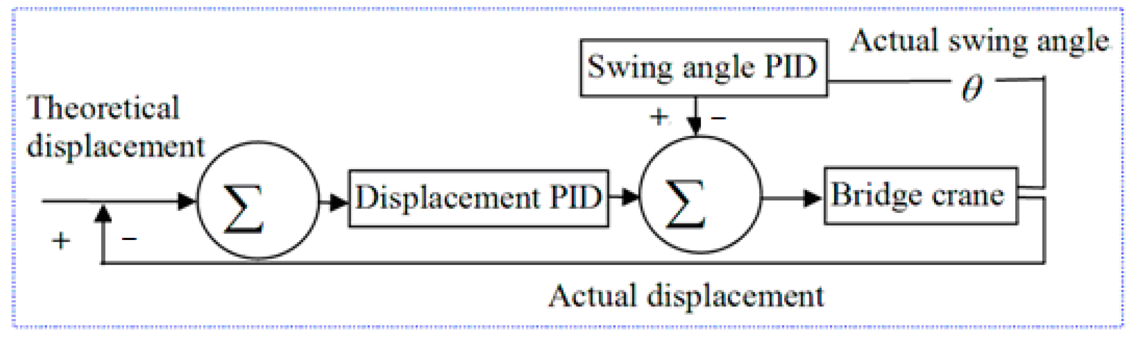
6.3.1. Simulation Analysis Model of a Fuzzy PID Anti-Sway Controller for the Bridge Crane
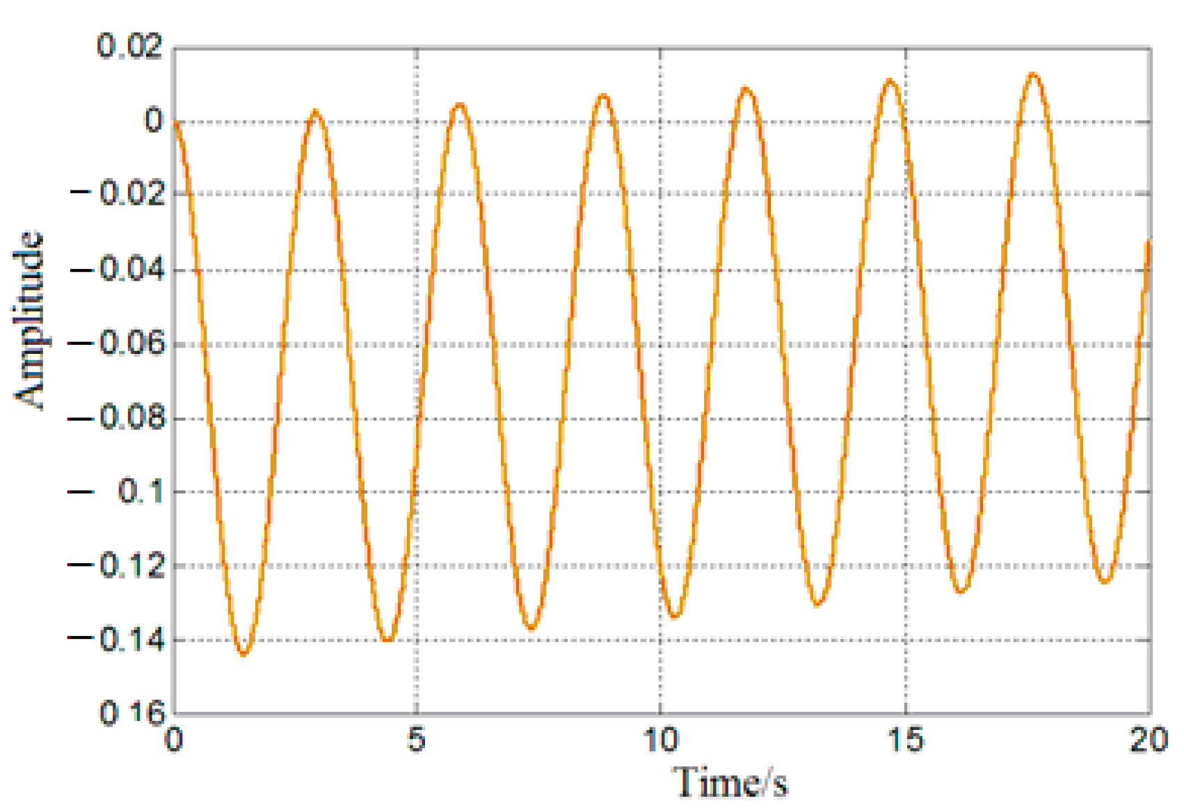
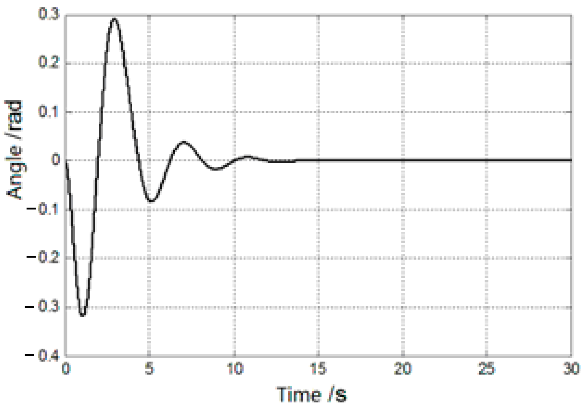
6.3.2. Simulation of the Anti-Sway Effect of the Fuzzy PID Controller
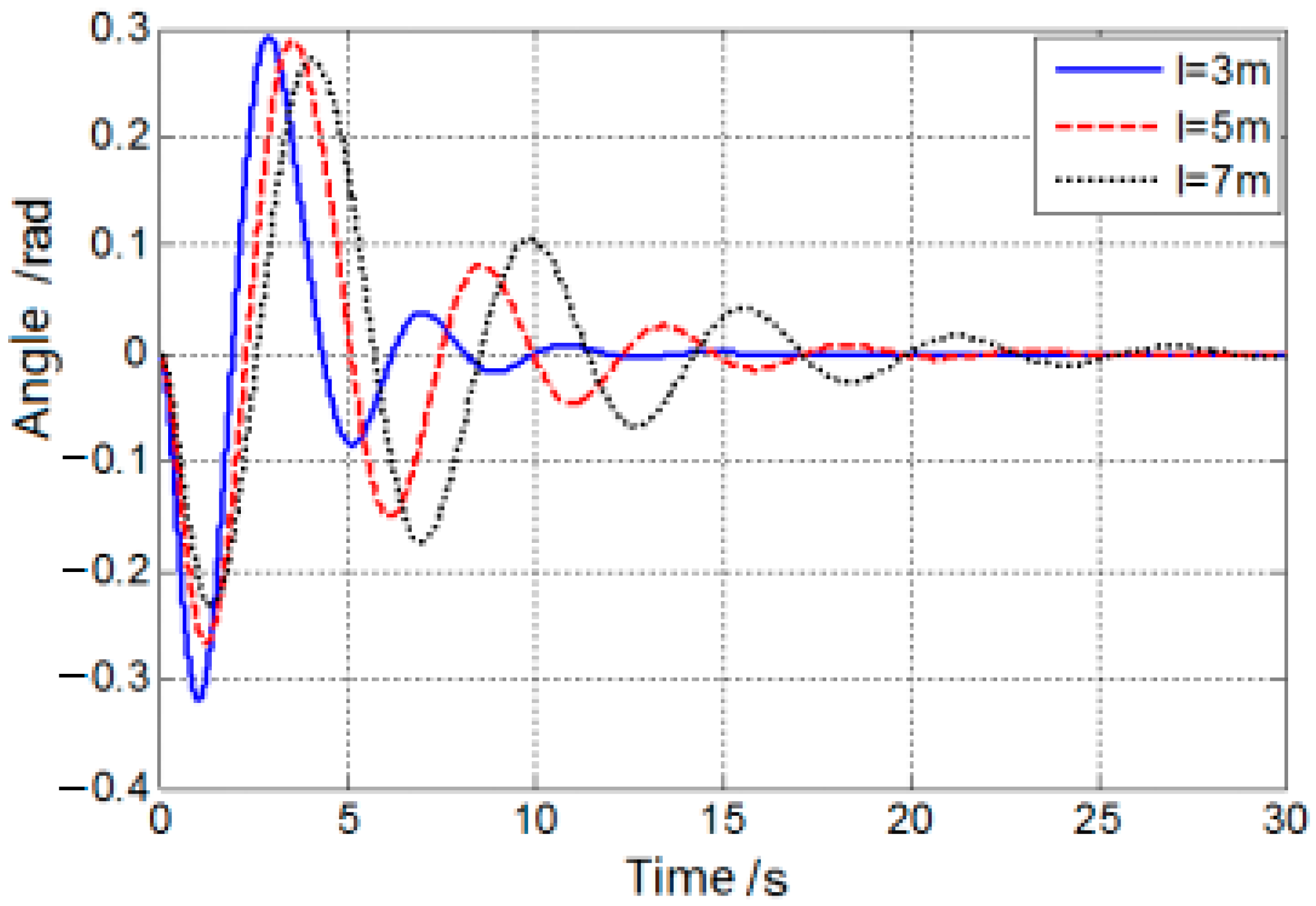
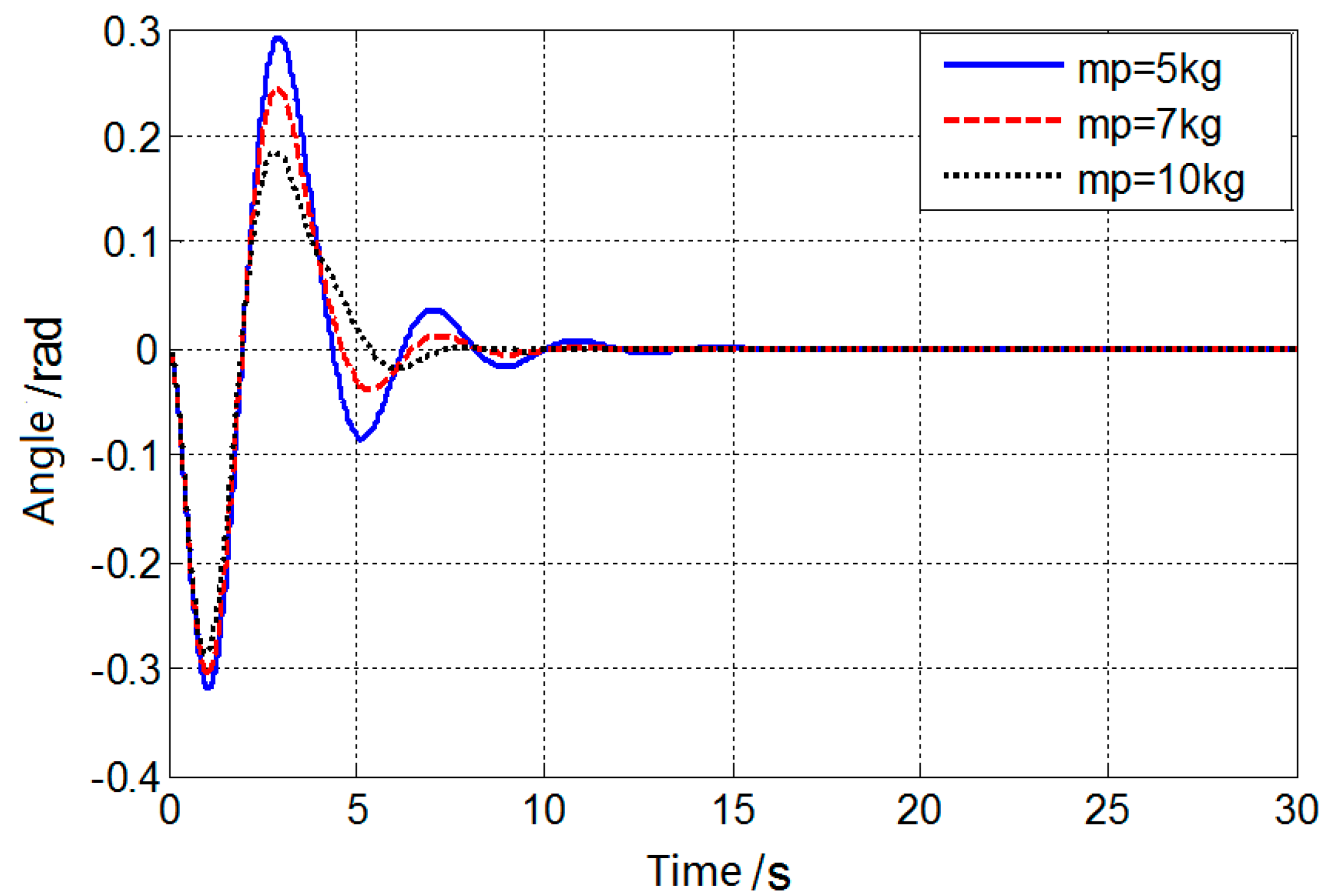
6.3.3. Simulation of Swing Angle under Different Rope Lengths and Load Masses
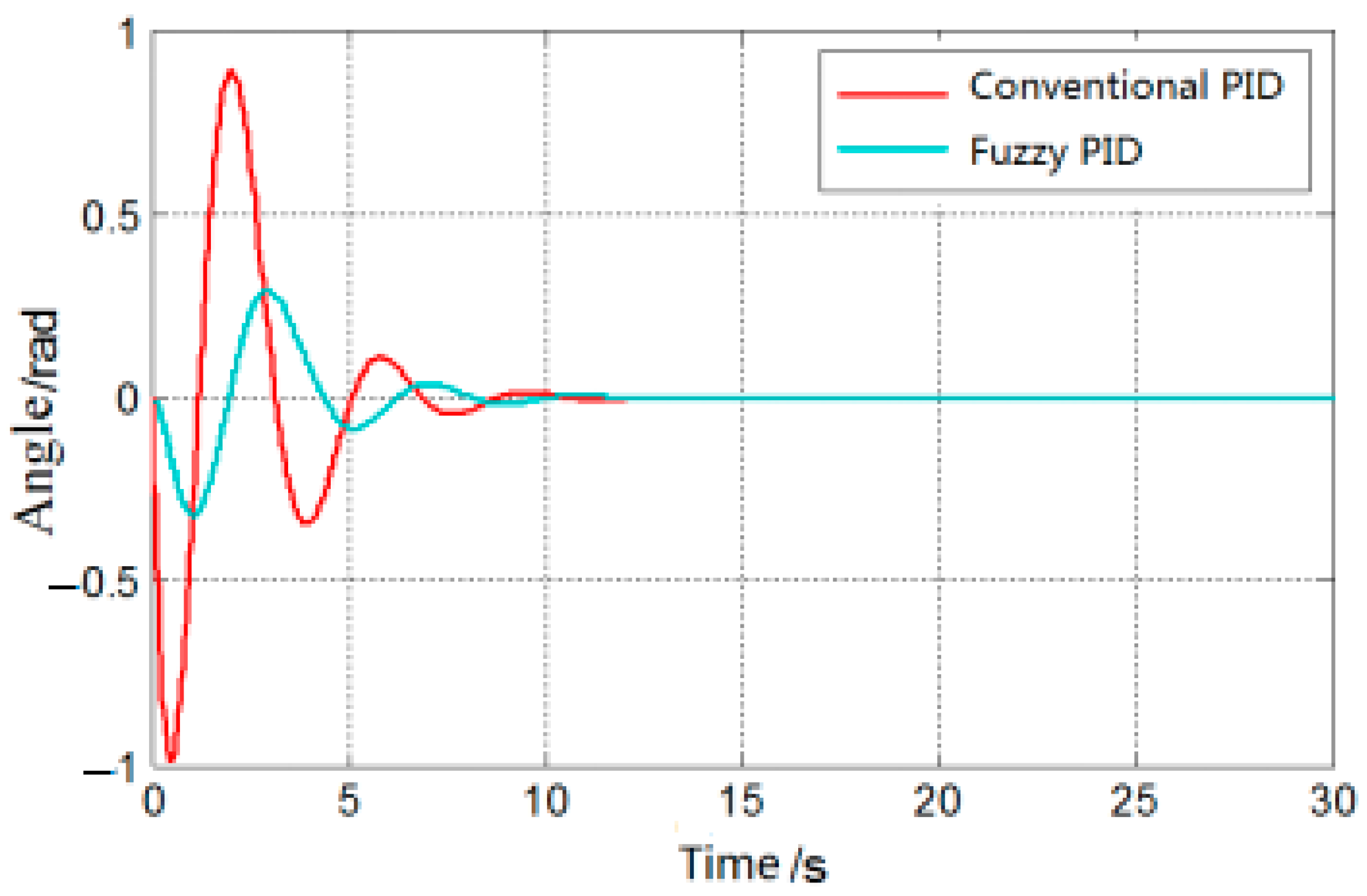
6.4. Comparison of Simulation Results between Conventional PID Anti Sway Controller and Fuzzy PID Controller
7. Conclusions
Author Contributions
Funding
Data Availability Statement
Acknowledgments
Conflicts of Interest
References
- Xu, X.-X. Research on Anti-Sway Technology of Bridge Crane Based on New Control Concept. Master’s Thesis, Taiyuan University of Science and Technology, Taiyuan, China, 2020. [Google Scholar]
- Gao, C.-L. Design and Research of Anti-Sway Control System for Bridge Crane. Master’s Thesis, Southwest Jiaotong University, Chengdu, China, 2019. [Google Scholar]
- Zhang, M.; Ma, X.; Rong, X.; Song, R.; Tian, X.; Li, Y. A novel energy-coupling-based control method for double-pendulum overhead cranes with initial control force constraint. Adv. Mech. Eng. 2018, 10, 168781401775221. [Google Scholar] [CrossRef]
- Ramli, L.; Mohamed, Z.; Jaafar, H.I. A neural network-base-d input shaping for swing suppression of an overhead crane under payload hoisting and mass variations. Mech. Syst. Signal Process. 2018, 107, 484–501. [Google Scholar] [CrossRef]
- Fan, B.; Zhang, W.-W.; Liao, Z.-M. Positioning and Swing Control of Bridge Crane Based on Load Energy Coupling. Control Eng. 2020, 27, 2077–2083. [Google Scholar]
- Pang, Z.-H.; Liu, F.; Tang, Y.; Wu, T. Research on the coupling of speed and swing angle of gantry crane. Manuf. Autom. 2021, 43, 138–142. [Google Scholar]
- Wu, Q.; Wang, X.; Hua, L.; Xia, M. Modeling and nonlinear sliding mode controls of double pendulum cranes considering distributed mass beams, varying roped length and external disturbances. Mech. Syst. Signal Process. 2021, 158, 107756. [Google Scholar] [CrossRef]
- Liu, L.; Yang, G.-L. Analysis of Lateral Vibration of a Class of Variable Section Beam Acted by Moving Mass. Eng. Mech. 2015, 32, 212–219. [Google Scholar]
- Zhou, Q.-C.; Wang, L.; Xiong, X.-L.; Zhao, J.; Tang, J.-C. Research on Mathematical Modeling Method of Overhead Crane Anti-sway Control System Considering Elastic Structure. Manuf. Autom. 2017, 39, 20–22+35. [Google Scholar]
- Yang, Z.-Y. Dynamic Modeling and Simulation of Lifting System of Bridge Crane. Master’s Thesis, Wuhan University of Technology, Wuhan, China, 2018. [Google Scholar]
- Yang, Q.; Ji, S.-Y.; Jiang, Z. Analysis and calculate-ion of skew operation of gantry crane. Lift. Transp. Mach. 2020, 47–52. [Google Scholar]
- GB/T3811-2008; Crane Design Specification. Beijing Hoisting and Conveying Machinery Design and Research Institute: Beijing, China, 2012.
- Yan, Z.-M. Crane wind load calculation problem-calculation of wind pressure (part 1). Refrig. Air Cond. Electr. Mach. 1981, 22–25. [Google Scholar]
- Ramli, L.; Mohamed, Z.; Abdullahi, A.M.; Jaafar, H.I.; Lazim, I.M. Control strategies for crane systems: A comprehensive review. Mech. Syst. Signal Process. 2017, 95, 1–23. [Google Scholar] [CrossRef]
- Yuan, X.-C.; Li, X.-D. Wireless sensor network for real-time monitoring of the force status of crane wire ropes. Heavy Mach. 2014, 72–74. [Google Scholar]
- Lu, F.-J.; Liu, H.-J.; You, L. Overview of Anti sway Control Algorithm for Bridge Crane. J. Ship Ocean Eng. 2020, 36, 1–7. [Google Scholar]
- Nguyen, A.T.; Taniguchi, T.; Eciolaza, L.; Campos, V.; Palhares, R.; Sugeno, M. Fuzzy control systems: Past, present and future. IEEE Comput. Intell. Mag. 2019, 14, 56–68. [Google Scholar] [CrossRef]
- Jiang, W.; Liu, G.; Wang, T. Fuzzy PID vibration control method under variable universe based on adaptive scaling factor. Eng. Mech. 2021, 38, 23–32. [Google Scholar]
- Zhao, B.-X.; Lu, N.; Lu, K.-X. Modeling and simulation of elevator landing door linkage device based on fuzzy PID. Electromechanical Eng. 2021, 38, 1038–1044. [Google Scholar]


| Additional friction resistance coefficient | |
| Deflection lateral force coefficient | |
| Single steel wire rope maximum tension | |
| Steel wire rope elastic modulus | |
| Wire rope metallic cross-sections area | |
| Coefficient of friction of large and small trolley wheels | |
| Pulley set magnification | |
| Corresponding pulley block efficiency | |
| (The mass of small trolley) | |
| (the mass of large trolley) | |
| (the mass of lifting heavy objects) | |
| (wire rope tension) | |
| (Full length of the wire rope below the reel without force) | 4 m |
| (additional resistance) | |
| (Stiffness coefficient) | |
| (Wire rope elongation) |
| Type | |||
| P | 0.5 | ||
| PI | 0.445 | 0.535 | |
| PID | 0.6 | 1.2 | 0.075 |
| Variable | Basic Universe | Fuzzy Universe | Quantification Factor/Scale Factor |
| [−12, 12] | [−4, 4] | 0.33 | |
| [−0.5, 0.5] | [−3, 3] | 6 | |
| [−1.5, 1.5] | [−3, 3] | 2 | |
| [−1, 1] | [−3, 3] | 3 | |
| [−10, 10] | [−6, 6] | 1.667 | |
| [−0.5, 0.5] | [−3, 3] | 0.167 | |
| [−8, 8] | [−6, 6] | 1.33 |
| // | ||||||||
|---|---|---|---|---|---|---|---|---|
| PB/NB/NS | PB/NB/NS | PM/NB/NB | PM/NM/NB | PS/NM/NB | ZO/ZO/ZO | ZO/ZO/NB | ||
| PB/NB/PS | PB/NB/PS | PM/NM/PS | PM/NM/PS | PS/NS/ZO | ZO/ZO/PS | ZO/ZO/NM | ||
| PM/NM/PB | PM/NM/PB | PM/NS/PM | PS/NS/PS | ZO/ZO/ZO | NS/PS/PS | NM/PS/NM | ||
| PM/NM/PB | PS/NS/PM | PS/NS/PM | ZO/ZO/PS | NS/PS/ZO | NM/PS/PS | NM/PM/PM | ||
| PM/NS/PB | PS/NS/PM | ZO/ZO/PS | NS/PS/NS | NS/PS/ZO | NM/PM/PS | NM/PM/NS | ||
| ZO/ZO/PM | ZO/ZO/PS | NS/PS/PS | NM/PM/PS | NM/PM/ZO | NM/PB/PS | NB/PB/NS | ||
| ZO/ZO/NS | NS/ZO/ZO | NS/PS/ZO | NM/PM/ZO | NM/PB/ZO | NB/PB/PM | NB/PB/NB | ||
Disclaimer/Publisher’s Note: The statements, opinions and data contained in all publications are solely those of the individual author(s) and contributor(s) and not of MDPI and/or the editor(s). MDPI and/or the editor(s) disclaim responsibility for any injury to people or property resulting from any ideas, methods, instructions or products referred to in the content. |
© 2023 by the authors. Licensee MDPI, Basel, Switzerland. This article is an open access article distributed under the terms and conditions of the Creative Commons Attribution (CC BY) license (https://creativecommons.org/licenses/by/4.0/).
Share and Cite
Yu, Z.; Dong, H.-M.; Liu, C.-M. Research on Swing Model and Fuzzy Anti Swing Control Technology of Bridge Crane. Machines 2023, 11, 579. https://doi.org/10.3390/machines11060579
Yu Z, Dong H-M, Liu C-M. Research on Swing Model and Fuzzy Anti Swing Control Technology of Bridge Crane. Machines. 2023; 11(6):579. https://doi.org/10.3390/machines11060579
Chicago/Turabian StyleYu, Zhen, Hao-Ming Dong, and Chang-Ming Liu. 2023. "Research on Swing Model and Fuzzy Anti Swing Control Technology of Bridge Crane" Machines 11, no. 6: 579. https://doi.org/10.3390/machines11060579
APA StyleYu, Z., Dong, H.-M., & Liu, C.-M. (2023). Research on Swing Model and Fuzzy Anti Swing Control Technology of Bridge Crane. Machines, 11(6), 579. https://doi.org/10.3390/machines11060579