Article

Research on Operation Conflict of Auxiliary Transport Locomotive in Complex Mine Based on Extended Petri Net

1
School of Mechanical Engineering, Anhui University of Science and Technology, Huainan 232001, China
2
State Key Laboratory of Mining Response and Disaster Prevention and Control in Deep Coal Mines, Anhui University of Science and Technology, Huainan 232001, China
3
College of Mechanical and Vehicle Engineering, Taiyuan University of Technology, Taiyuan 030024, China
*
Author to whom correspondence should be addressed.
Machines 2023, 11(5), 552; https://doi.org/10.3390/machines11050552
Submission received: 13 April 2023 / Revised: 6 May 2023 / Accepted: 10 May 2023 / Published: 13 May 2023
(This article belongs to the Section Vehicle Engineering)

Abstract

:
Aiming at the operation conflict problem of multi-objective, multi-path and multi-vehicle relay during mine locomotive operation under complex geological conditions, a mine operation of locomotive modeling method based on an object-oriented stratified timed Petri net is proposed. In order to load and transport materials as object oriented, which are combined with the mine operation of locomotive rules and time constraints, stratified modeling of an underground roadway route is carried out. In addition, given token time parameters to describe the dynamic behavior of the locomotive, through the model to analyze the operation of a mine transport locomotive, the correlation matrix and accessibility tree analysis are used to study the conflict. Taking the actual operation of a locomotive in a complex mine in Guizhou as an example, the operation of locomotive behavior model was established to detect the interval and time of operation conflicts. The experimental results show that the proposed operation of locomotive modeling and conflict analysis method are effective and feasible, and have important application value to the safe operation of a mine production system.

1. Introduction

The quantity and variety of auxiliary transport and distribution materials in mines are different, and the distribution needs are many. Limited by the complex geological conditions, the mine transport environment is harsh, the roadway route is complex, there are many turns, the slope changes greatly, the working face changes frequently, and a single transport vehicle does not meet the transport requirements. The status quo of underground multi-objective, multi-path and multi-vehicle locomotive operation is analyzed. How to establish an analysis model of underground locomotive safe operation behavior, avoid locomotive operation conflict, and improve the efficiency and reliability of underground auxiliary transportation of coal mines is crucial for efficient mining and safe production [1].
The operation process of complex mine locomotives is essentially a discrete time dynamic system [2,3]. As a computer model [4], Petri net has a natural advantage in the study of discrete dynamic system response due to its concurrent, asynchronous and parallel characteristics [5,6].
Many researchers studied the global operation conflict resolution and deadlock-free scheduling of ground vehicles by using the reachable map model and constructing constraint rules [7,8,9]. By analyzing the running time interval of ground vehicles, some researchers put forward the alternative graph theory to solve the conflict analysis model to solve the local rule conflict of vehicles, effectively improving the solving efficiency of vehicle models [10,11,12]. Menghuan Hu et al. [13] obtained the deadlock marker of the model by solving the integer linear programming problem and replacing the whole part with a small part of the accessibility graph covered by GFBM. Emad Abouel Nasr [14] combined the Petri net and deadlock prevention strategy, established Petri net model through matlab, analyzed deadlock by siphon control and iteration, and verified the behavior permissibility of different systems. Yan Xuanxuan et al. [15] started with the electric locomotive and ensured the efficient operation of an underground electric locomotive through the construction of a deadlock-free scheduling strategy through a theoretical calculation model and the combination of a theoretical analysis and experiment. Cao Chunling et al. [16] used hierarchical color Petri nets to model the dispatching system of trackless wheel cars, and analyzed parameters such as frequency and time distribution of segment use, so as to reduce transportation accidents and improve the utilization rate. Cao Zhengcai et al. [17] conducted hierarchical modeling of a production line from top to bottom and designed and optimized a multi-factor scheduling scheme by combining genetic algorithms. Obviously, most of these studies focus on the conflict analysis of ground vehicles or the deadlock-free scheduling of a single type of locomotive in underground coal mines, while few studies on the multi-target and multi-type vehicle relay transport conflict in underground coal mines.
Petri nets also play an important role in intelligent transportation and flexible manufacturing [18]. Intelligent transportation mainly verifies the bound-ness and activity of the model based on the accessibility state, reduces the computing time, improves the signal control design level of intersections, and realizes the conflict analysis of the behavior of vehicles and pedestrians at intersections [19,20]. Aiming at the deadlock problem of a flexible manufacturing system [21], combined with the modeling characteristics of a Petri net, a decomposition control strategy is established through shared transformation, a vector coverage method is used to avoid redundancy, and the computing space is optimized [22,23]. The reconstruction modeling efficiency of an automated manufacturing system can be improved by constructing complex Petri net models and adopting state transition methods [24]. Xu Jian et al. [25] introduced an extended Petri net into the aircraft assembly line balance problem and adopted a heuristic algorithm to realize station position optimization. Albert Pla et al. [26] combined an extended Petri net with a medical maintenance environment to design an intelligent workflow system of process monitoring and delay prediction to analyze and predict delay equipment. The data of these studies are often taken from benchmark examples in daily life, and problems are actually analyzed by constructing different types of Petri models, which makes it unclear whether this research method is suitable for the conflict analysis of locomotive operation in underground coal mines.
Aiming at the multi-objective, multi-path and multi-vehicle operation conflict of a mine locomotive under complex geological conditions of mining, this paper sorted out the locomotive operation rules on the basis of traditional mine vehicle operation. A Hierarchical Object-oriented Timed Petri Net (HOTPN) [27,28] based operating model of a mine locomotive was proposed.
According to complex mine geological conditions, time parameters are introduced to “time assign” a basic Petri net, which is used to describe the time characteristics of a mine locomotive. In addition, taking loading and distributing materials as object-oriented, the locomotive route in the actual operation process is stratified, and the operation model of a mine auxiliary transport vehicle is established. A token is used to represent the actual running vehicles, and the token running in each interval is given a time parameter to represent the time consumed by the locomotive in the interval. The model is used to analyze the behavior of the locomotive in the process of a mine auxiliary transportation and solve the running conflict of auxiliary transportation vehicles. On the premise of ensuring safety, an extended Petri net is used to analyze the operation of the underground locomotive, and the validity and feasibility of the model are verified by experiments.

2. Scheduling Modeling of Auxiliary Transport Vehicles Based on HOTPN

2.1. Definition of HOTPN

The Hierarchical Object-oriented Timed Petri Net description system consists of six tuples. HOTPN = (P, T, F, D, M, Q), T is the transition set, T = {T1, T2, T3, …, Tm} (m = |T|). P is the place set, P = {P1, P2, P3, …, Pn} (n = |P|), and T∩P = Φ, T∪P ≠ Φ. F stands for directed arc set, F ( P   ×   T ) ( T   ×   P ) . D is the transition trigger delay time set, representing the time function of Token v in the place, and D(pi, v) = τ, τ is the trigger delay time, representing the time that token v occupies pi in the place. M:P→N is the identification of Petri net, the i-th element represents the number of tokens in the place i. M0 is the initial identifier. Define the place pi P identifier m p i = d C ( p i ) | m p i ( d ) | d . HOTPN identifier is M = [ m p 1 ,   m p 2 ,   m p 3 ,   ,   m p m ] T . Q is a set of states, and each subnet q     Q is assigned an object-oriented Petri net.
Definition 1.
before and after sets.
Assuming that S ∈ T∪P, the previous set * S and the subsequent set S * of S belong to directed arc set F, which can be expressed as:
* S = m | ( m ,   n ) F S * = n | ( n ,   m ) F
Definition 2.
Transition trigger delay.
When M   [ t k   >   M ] , the trigger delay time of the new enable transition is equal to the time parameter of enabling the transition token. There is a transition where ti enabled both M identifier and M’ identifier, namely t i enable ( M ) enable ( m ) . After tk is triggered, the triggering delay of ti changes accordingly. Assume the delay time τ, identifying tk under M identifier. The delay time τ i of transition t k . The trigger delay time of transition t i under M’ is τ i ’, τ i = τ i τ .
Definition 3.
Enable transition rules.
Transition t i T under the identifier M can make M   [ t k > M ] , if and only if
p P : M p = M p I p , t + O ( p , t )

2.2. HOTPN Model Construction

In order to accurately describe the operation conditions of complex mines and feed-back the real scene of coal mine auxiliary transportation, HOTPN is based on a mine locomotive operation process modeling top-down, from a static to dynamic hierarchical process, and each step is endowed with time characteristics. Specific modeling steps [29] are as follows:
Step 1: According to the mine auxiliary transport robot “electric locomotive-monorail crane” process, the model is stratified.
Step 2: According to the operation hierarchy model of a mine auxiliary transport robot, take material distribution as an independent object. First, Set E i ( i = a ,   b ,   c ,   d ,   e ,     ) represents the electric locomotive transport robot. Then, Set M i ( i = a ,   b ,   c ,   d ,   e ,   ) represents a monorail crane transport robot. Next, establish the object for material distribution Oa = { E a ,   E b ,   E c ,     ;   M a ,   M b ,   M c ,   } .
Step 3: In the process of auxiliary transportation, the place represents the shaft station, wind door and track switch through which the mine locomotive actually runs. Transition represents the movement of the locomotive from the current interval to the next interval. Moreover, time characteristic T is assigned to the running state of the locomotive in the place, and the transport roadway model is established in layers.
Step 4: Establish the transition trigger delay time. When M   [ t k > M ] , enable transition. The trigger delay time of the new enabled transition is equal to the time parameter of enabling the transition token. Transitions t j when both M and M’ are enabled, tj ∈ enable(M)∩enable(M′). After ti is triggered, the triggering delay of tj changes accordingly.
Step 5: Establish rules for enabling and triggering transitions between objects. If the transition   t T contains token v in the input place under the identity matrix M, then the transition t is enabled under the identity M, which is expressed as t ∈ enable(M). Secondly, after the enable transition t is enabled and triggered after the corresponding trigger delay τ, token v is transferred from the input place to the output place.
Step 6: Create the initial identity M 0 , and display all the place identifiers. Then, use a directed arc to connect the input information place (IP)/output information place (OP) and transition (T) in all established places according to the locomotive operation relationship. Finally, the hierarchical HOTPN model is established.

3. Analysis of Mine Locomotive Operation Conflict

3.1. Analysis of Locomotive Operation Rules

Based on the special operating environment and safety performance requirements of underground coal mines, underground auxiliary transportation routes are usually divided into several sections according to the factors such as station and working face. Due to complex geological conditions, a single locomotive cannot meet the requirements of auxiliary transport materials distribution, so it needs to be reproduced in the locomotive shaft station. Therefore, a mine locomotive transportation mainly involves four main rules, including interlocking of the locomotive running into the road, opening and closing of the wind door and other situations. The specific rules are as follows:
  • Interlocking rules of locomotive approach interval scheduling:
    (1)
    Application for locomotive pre-occupation. The mine locomotive receives the operation instruction of the dispatching platform, and when the operation of the section is about to end, it will initiate the application for pre-occupation of the next section;
    (2)
    Scheduling platform approach interval interlocking calculation. The dispatching platform summarizes and reviews the application for pre-occupation of the locomotive’s approach interval, determines whether it meets the locomotive’s operation requirements according to the interlocking conditions, and rejects the application for pre-occupation that does not meet the requirements or re-plans the approach interval;
    (3)
    Pre-occupied interval locking. For the approach interval meeting the requirements, the dispatching platform will issue the permission to occupy the interval instruction to open the next approach interval for the locomotive.
  • Wind door opening and closing interlock rules:
    (1)
    Application for wind door opening. When the transport locomotive is about to arrive at the wind door position, issue the wind door opening application to the dispatching platform;
    (2)
    Wind door interlocking calculation of dispatching platform. The dispatching platform receives the wind door opening application of the locomotive, and then determines whether the wind door is open or not according to the requirements of the wind door opening and closing interlock. For a situation that does not meet the requirements, the dispatching platform will reject the wind door opening application;
    (3)
    The wind door is closed. For a wind door opening application that meets the requirements, the dispatching platform will issue the wind door opening instruction, and the damper that receives the instruction from the dispatching platform will open and close each wind door successively to ensure the normal underground ventilation system.
  • Interlocking rules of station transshipment:
    (1)
    Application for yard transshipment. When the locomotive arrives at the transfer station, the vehicle transfer application is issued to the dispatching platform;
    (2)
    Transfer judgment of dispatching platform. The dispatching platform will review the application for locomotive reprinting, judge whether the locomotive needs to reprint, and judge whether the reprinting device meets the reprinting requirements;
    (3)
    Locomotive transfer device is opened. The dispatch platform issues the locomotive transfer instruction, the automatic blocking device opens the fixed locomotive position, starts the transfer robot handling the standard container, and starts the material transfer;
    (4)
    Close the locomotive transfer device. After receiving the feedback signal of material transfer completion, the dispatching platform closes the blocking device, closes the transfer robot, and the locomotive starts to run after the transfer is finished.
  • Other cases: the dispatching platform shuts down the allowable approach interval instruction of the locomotive, makes sound and light alarms and starts the emergency management function until the alarm is contacted, when faced with some locomotive incorrect operations, such as: personnel breaking into the locomotive running route, the vehicles breaking the red light, the locomotive moves into the track switch by mistake, the wind door is not opened and closed in time, etc.

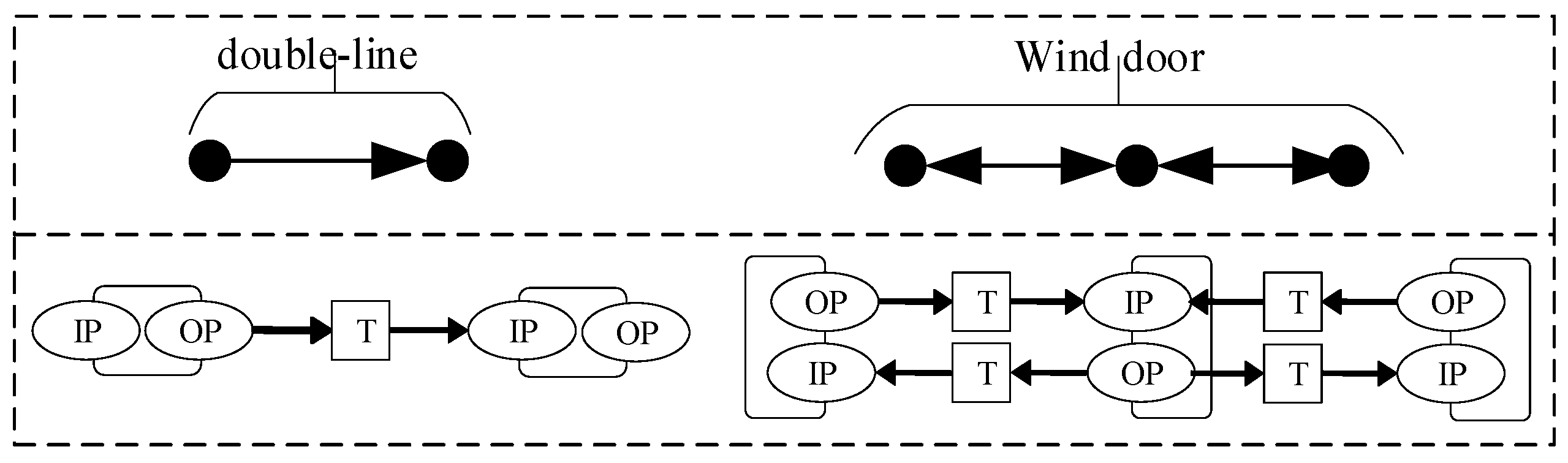
3.2. Modeling of Running Route

Due to the great change of geological conditions in the mine, the route of the auxiliary transport locomotive from the industrial square to the working face is relatively complex. The locomotive enters the mine from the main inclined shaft, and finally completes the material distribution through the locomotive shaft station, wind door, track switches and other links. Underground transportation routes, as shown in Figure 1, can be divided into four types: a single-line operation section, double-line operation section, track switch operation section and wind door operation section. The waste materials of each underground working face are transported back to the surface industrial square in accordance with this route. Among them:
  • A single-line operation section means that locomotives are allowed to run in both directions;
  • A double-line operation section allows the locomotive to run in one direction;
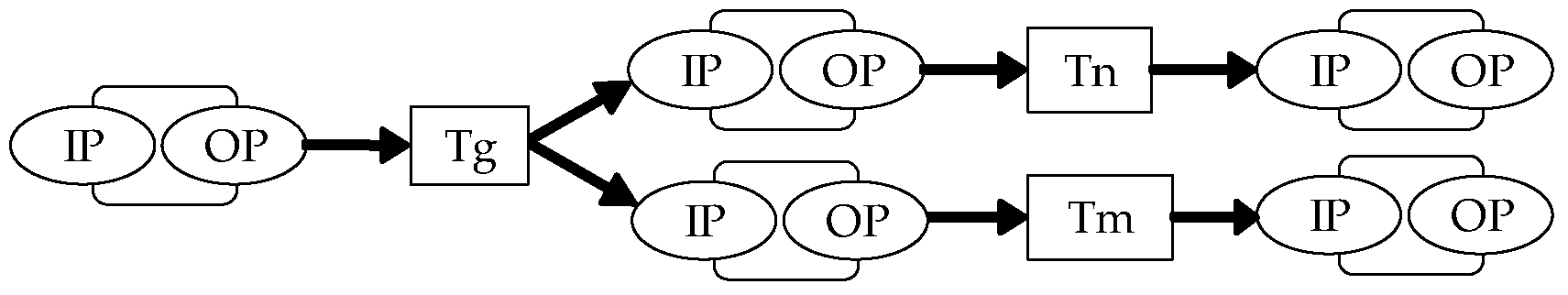
  • A track switch operation section refers to the presence of switch nodes in locomotive operations, and the locomotive heads to different sections according to the direction of the switch. The switch includes a ground track switch and empty track switch;
  • A wind door operation section refers to the three wind doors opening and closing successively when the locomotive runs to the location of the underground wind door.
The conventional expression method of the Petri net is combined with the underground operation route, and the depot is used to represent the yard, working face or wind door. The change represents the movement of materials from one state to another state (materials are transferred from one kind of locomotive to another kind of locomotive, and the locomotive carrying transportation materials from one section to another section). In order to more clearly describe the place changes, set the Input information Place (IP) and Output information Place (OP) for the changes in the place, and use T for state transitions. According to the common working conditions of the mine roadway, the mine locomotive transport path network is established, as shown in the figure, which is used to describe the state of auxiliary transport vehicles in the actual transport process and improve the universality of the model.

3.3. Analysis of Locomotive Operation Conflict

3.3.1. Constraints on Locomotive Operation

The underground operation space and transportation resources of coal mines are limited. The inherent conflict of a mine locomotive operation on the limited resources is mainly reflected in the monopoly of the underground section. Therefore, the underground locomotive operation conflict mainly includes capacity conflicts and time conflicts. Since many stations are arranged under the mine now, the probability of capacity conflicts is less. This paper mainly starts from the perspective of time conflicts, including the running time conflict of the locomotive in the warehouse, the running time conflict between the locomotive and the container material transfer time conflict, the tracking interval time conflict, and the different locomotive route time conflict. The operation of auxiliary transport vehicles must meet the rules of underground coal mine locomotive transport.
In view of time conflicts, the operation constraints of auxiliary vehicles are established:
The locomotive runs according to the most basic running safety requirements as shown in Figure 2. When receiving dispatching instructions, the vehicle must keep a certain time interval, and the trigger delay time of t h and t k should meet the requirement of τ k τ h     Δ t , where ∆t is the minimum time interval.
Under complex geological conditions, roadway transportation often involves the cooperative transport of materials by electric locomotive and monorail crane, and material transfer is carried out at the bottom of the well yard and the upper yard. As shown in Figure 3, let the monorail transfer robot take tr from triggering to grasping a standard container to completing the transfer. The trigger conditions of tm and tn should be satisfied: τ 1 τ 2       nt r .

3.3.2. Accessibility Tree Analysis

According to the characteristics of stratified time allocation, the real-time running data of a mine running locomotive are sorted out, and the Petri route of a mine auxiliary transportation is constructed. Combined with the real-time operation and transfer data of mine locomotives, the state of Petri net model at a certain moment is taken as the initial state. Through the reachable tree analysis method, the future reachable state of locomotive operation is deduced, and the potential conflict is determined according to the conflict rules.
In the algorithm described below: The current node is set to M o
M set = φ
In the above formula: M set is a finite set of identifiers.
T g = T g 0
In the above formula: T g is the global time; and T g 0 is the initial global time.
Generating a new logo after successive judgment can trigger all the changes t { t | τ x = min t   enable M ( τ ) } ; trigger transition M   [ t > M ] .
Set M to the current node.
M set = M set { M }
T g = T g + τ x
For t i { T   enable ( M ) } , p t i * , if m p = K p τ i     min t x enable M P   τ x + t , it indicates that there is a vehicle tracking interval conflict at p under identification M. Among them, min t x enable M P   τ x represents the earliest time to trigger the enable transition in the p set of the place under M.
The algorithm flow of conflict analysis of an accessibility tree for an auxiliary transport locomotive [30] is shown in Figure 4:

4. Case Analysis

In this paper, taking a complex geological mine in Guizhou as an example, aiming at the situation of multi-object, multi-path and multi-equipment relay in the auxiliary transportation process, an object-oriented time-assigned stratified Petri net model is established. In the process of vehicle operation, think of things that need to be loaded and distributed as object-oriented, the token means the actual transfer vehicle and stratify locomotives in actual operation. Additionally, the token is given a time parameter to represent the time consumed by the locomotive in each interval. The model is used to analyze the behavior of the locomotive in the process of a mine auxiliary transportation and detect the running conflict of auxiliary transportation vehicles.

4.1. Operation Modeling of Auxiliary Transport Locomotive

Under complex geological conditions, the roadway slope changes greatly, and it requires a variety of vehicle relay transports, for the auxiliary transport vehicle segment crossoperation. As is shown in Figure 5, starting at the industrial square (Ch1), between the shaft station b (Ch2) to the upper yard (Ch3) and working face 1 (Cw1) and working face 2 (Cw2), this section is operated by an electric locomotive. Between the upper locomotive yard (Ch3) and working face 3 (Cw3) and working face 4 (Cw4), this section is transported by monorail crane. The transport locomotive is reproduced at the upper yard. Among them, the electric locomotive needs to pass through a set of wind doors to reach the upper yard, and the monorail crane needs to pass through a set of wind doors to reach the working face after being transferred in the upper yard. Similarly, the underground material transportation also needs to pass through a transport corresponding locomotive relay, and finally return to the surface industrial square.
In this paper, combined with the construction rules of the Petri net mentioned above, the operation model of a mine locomotive was established, as shown in Figure 6, And construct the auxiliary transport robot information input and output Place, as shown in Table 1.

4.2. Operation Modeling of Auxiliary Transport Locomotive

The correlation matrix A of the Petri net model of complex mine locomotive operation is:
A = 1 0 0 0 0 0 0 0 0 0 0 0 0 0 0 0 1 0 0 0 0 0 0 0 0 1 1 0 0 0 0 0 0 0 0 0 0 0 0 0 0 0 0 0 0 0 0 0 0 0 0 1 1 1 0 0 1 0 0 0 1 1 0 0 0 0 0 0 0 0 0 0 0 0 0 0 1 0 1 0 0 0 0 0 0 0 0 0 0 0 0 0 0 0 0 0 0 0 0 0 0 1 0 0 0 1 1 0 1 0 0 0 0 0 0 0 0 0 0 0 0 0 0 0 0 0 1 1 0 0 0 0 0 0 0 0 0 0 0 0 0 0 0 0 0 0 0 0 0 0 0 1 1 0 0 0 0 0 0 0 0 0 0 0 0 0 0 0 0 0 0 0 0 0 0 0 0 1 1 0 0 0 0 0 0 0 0 0 0 0 0 0 1 0 0 0 0 0 0 0 0 0 0 1 0 0 0 1 1 0 0 0 0 0 0 0 0 0 1 0 0 0 0 0 0 0 0 1 0 0 1 1 0 1 1 0 0 0 0 0 0 0 0 0 0 0 0 0 0 0 0 0 0 0 0 0 0 1 0 1 0 0 0 0 0 0 0 1 0 0 0 0 0 0 0 0 0 1 1 0 0 0 1 0 0 0 0 0 0 1 0 0 0 0 0 0 0 0 0 0 0 0 0 0 0 0 0 1 1 0 0 1 0 0 0 0 0 0 0 0 0 0 0 0 0 0 0 0 0 0 0 0 1 1 0 0 0 0 0 0 0 0 0 0 0 0 0 0 0 0 0 0 0 0 0 0 0 1 1 0 0 0 0 0 0 0 0 0 0 0 0 0 0 0 0 0 0 0 0 0 0 0 1 1
Pm is the start place, and Pi (i = 1, 3, 6, 8, 11, 14, 16) is the yard place. Pi (i = 2, 4, 5, 7, 9, 10, 12, 13, 15) is the interval place, and Pn is the end place. The running route of the locomotive is sorted out, as shown in Table 2, and the time parameter of the token in the place is shown in Table 3.
The operation of the above auxiliary transport locomotive is shown in Figure 7. We can directly observe the location of the collision between vehicles.

4.3. Reachable Tree Structure and Conflict Analysis

Initial identification of Petri nets: M 0 = [ m s ] T = [ 1 R 1 + 1 R 2 + 1 R 3 + 1 R 4 + 1 R 5 + 1 R 6 ] T . According to the auxiliary transportation scheduling schedule, the initial identifier M0 first triggers P1 to form M1. Under M1, transitions t1 and t19 belong to the new enable transition. Then, τ 1 = 3 , τ 19 = 9 , and the transition t1 is triggered first.
Transition t1 triggers the transformation to obtain M 0   [ t 1 > M 1 ] .
M 1 = [ m s , m 2 ] T = [ 1 R 1 + 1 R 2 + 1 R 3 + 1 R 4 1 R 5 1 R 6 ]
Under the identifier M1, transitions t2 and t19 belong to the new enable transitions, τ 2 = 8 , τ 19 = 7 , and the transition t19 is triggered.
Transition t19 triggers the transformation to obtain M 2   [ t 19 > M 1 ] .
M 2 = [ m s , m 16 ] T = [ 1 R 1 + 1 R 2 + 1 R 3 + 1 R 4 1 R 5 + 1 R 6 ] T
Under the identifier M2, transitions t2 and t20 belong to the new enable transition, τ 2 = 8 , τ 20 = 11 ,and the transition t2 is triggered.
Transition t 2 triggers the transformation to obtain M 3   [ t 2 > M 2 ] .
M 3 = [ m s , m 3 ] T = [ 1 R 1 + 1 R 2 + 1 R 3 + 1 R 4 1 R 5 + 1 R 6 ] T
According to the process of conflict analysis of an accessibility tree, the future reachable identifiers of HOTPN were constructed, and the conflict detection was carried out one by one to obtain the conflict information, as shown in Table 4 (set the minimum time interval standard t ).
As shown in Figure 8, when T = 20 min, the preceding set of transition t12 is * t 12 = { P 5 } The next set of transition t12 is t 12 * = { P 11 } . P5 in the place identifies M 5 = { 1 R 2 ; 1 R 3 } , M 5 = k P 5 = 1 , M 11 = k P 11 = 2 ; enable M P 11 * = { t 12 } , the trigger transition of R2 is τ 12 = 4 , the trigger transition of R3 is τ 12 = 2 , and the trigger delay time of transition t_12: τ 12   >   τ 12 + t . According to the conflict decision theorem, the place P5 has a running conflict.
When T = 18 min, the preceding set of transition t21 is * t 21 = { P 11 } , and next set of transition t21 is t 21 * = { P 5 } . P5 in the place identifies M 5 = { 1 R 2 ; 1 R 3 ; 1 R 6 } , M 5 = k P 5 = 3 ; enable M     P 5 * = { t 4 ,   t 21 } . For R2 and R3, the trigger transition of R2 is τ 12 = 4 , the trigger transition of R3 is τ 12 = 2 and the trigger transition of R6 is τ 22 = 4 . Obviously, τ 22 + t > τ 12 , τ 22 + t τ 12 . According to the conflict decision theorem, it can be seen that P5 in the place has the opposite conflict.
When T = 29 min, the preceding set of transition t11 is * t 11 = { P 10 } , and the next set of transition t11 is t 11 * = { P 3 } . The preceding set of transition t22 is * t 22 = { P 5 } , and the next set of transition t22 is t 22 * = { P 3 } . Place P3 is the identifier M 3 = { 1 R 4 ; 1 R 5 } , M 3 = k P 3 = 2 ; enable   M P 3 * = { t 11 , t 22 } , the trigger transition of R4 is τ 11 = 2 , the trigger transition of R5 is τ 22 = 3 , and τ 11 = τ 11 + t . According to the conflict decision theorem, it can be seen that there is a path conflict in P3.

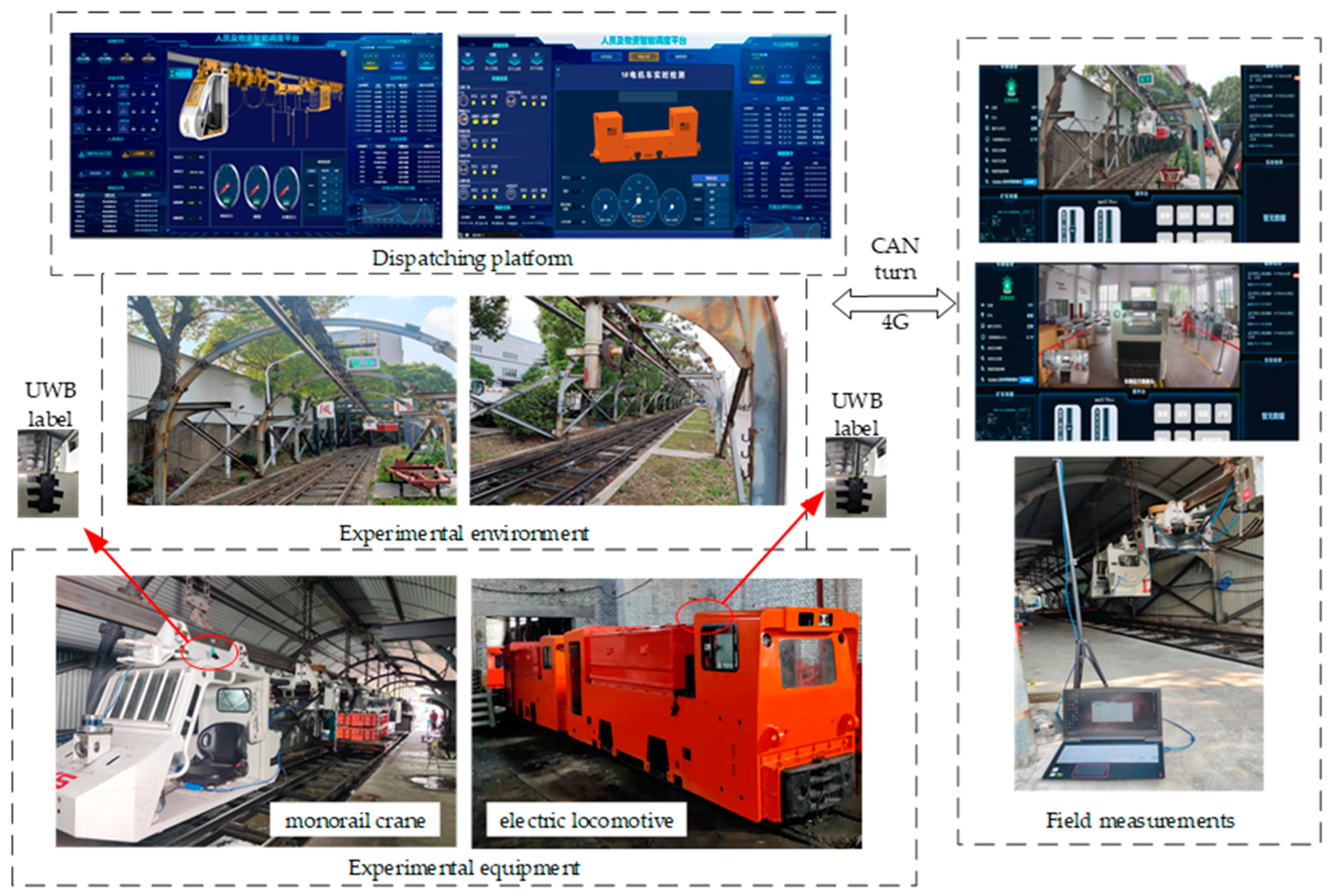
5. Experimental Verification

In order to verify whether the location and time of the conflict that occurred during the operation of the above multiple vehicles are correct, based on the intelligent dispatching system of auxiliary transportation, the locomotive is allowed to carry UWB on-board positioning labels during operation. The UWB positioning base station is arranged in the experimental site to give real-time feedback to the locomotive position information, and the dispatching platform can remotely monitor the vehicle operation information [31,32]. As shown in Figure 9, through interface protocol and data transmission protocol, the dispatching platform can obtain the on-board camera in real time and arrange the camera information at the key transport nodes to construct the real-time monitoring system of a mine locomotive dispatching and verify the effectiveness of the collision detection of locomotive operation.
In order to study the behavior of a mine locomotive in actual operation, the experimental platform of an auxiliary transport locomotive operation scheduling system was built. See Figure 10. During the experiment, the electric locomotive and monorail crane were made to carry UWB positioning labels. According to the dispatching instructions, the experimental environment of the positioning base station was arranged in advance. The dispatching platform displayed the position of the running locomotive in real time, and the real-time monitoring image of the camera was used to judge whether the locomotive had running conflicts, so as to verify the effectiveness of the above method.
In this paper, the operating electric locomotive and monorail crane are numbered. Then, E i ( i = a ,   b ,   c ,   d ,   e ,   ) denotes the electric locomotive transport robot, and M i ( i = a ,   b ,   c ,   d ,   e ,   ) represents a monorail crane transport robot. The locomotive runs along the preset path according to the dispatching instructions. The dispatching platform records the time through each library and draws the Gantt chart of locomotive running as shown in Figure 11.
The auxiliary transport locomotive starts running at 9:00 and runs to the target point through the corresponding place. By comparing the vehicle running results of the Gantt chart and vehicle running chart of locomotive actual running, we can obtain: at 9:18, Ea heading towards P14 and Eb heading towards P16 collided with Ee heading from P14 to P1 in place P5; at 9:20, Eb heading towards P16 collided with Ea heading towards P14 in P5. At 9:29, Ea and Eb, which were heading towards the direction of P1 at the same time, clashed in place P3.
During the experiment, the electric locomotive and monorail crane equipment received the instruction from the dispatching platform, ran in the simulated roadway according to the instruction, and simulated the behavior of the auxiliary transport robot in the place, so as to verify whether the conflict detected by the above method is correct. However, in the actual material transportation process of mines, the number and operation parameters of auxiliary transport locomotives are relatively complicated, and the speed of various transport locomotives is inconsistent. It is difficult to accurately control the loading and turning time, and factors such as locomotive damage, switch switching and wind door opening and closing response speed affect the actual operation information of the locomotive. Therefore, it is necessary to build a model according to the characteristics of the actual route of the auxiliary transport locomotive to improve the efficiency and accuracy of conflict detection.

6. Conclusions

Aiming at the operation conflict problem of multi-objective, multi-path and multi-vehicle transfer relay during mine locomotive operation under complex geological conditions, this paper proposes a mine locomotive operation modeling method based on an object-oriented stratified timed Petri net. The layered modeling of the mine route is carried out, and the running time characteristics of locomotives are endowed, which intuitively reflects the complexity and dynamics of underground locomotive operation. Additionally, the actual running condition of locomotives is reflected by the reachable tree analysis, and the conflict detection and analysis of locomotives in the model are carried out by using the correlation matrix method and the reachable tree analysis method. Additionally, the accuracy and feasibility of this conflict detection and analysis method are verified by experiments, which provide a useful reference for underground locomotive operation conflict modeling and analysis.
In the next step, conflict resolution will be carried out on the basis of conflict detection, so as to build a deadlock-free scheduling model for mine locomotive, improve the balance rate of underground route operation, and form an automatic scheduling strategy for mine locomotives.

Author Contributions

Conceptualization, G.W. and X.Y.; data curation, G.W., X.Y. and H.D.; formal analysis, G.W., X.Y. and H.D.; funding acquisition, Z.K. and H.D.; Investigation, G.W. and X.Y.; Methodology, G.W. and X.Y. and K.W.; project administration, Z.K. and K.W.; resources, Z.K. and K.W.; software, G.W.; supervision, Z.K.; validation, G.W., X.Y. and H.D.; visualization, G.W., X.Y. and H.D.; writing original draft, G.W. and X.Y.; writing—review and editing, G.W., X.Y. and H.D. All authors have read and agreed to the published version of the manuscript.

Funding

This work was supported by the Anhui Provincial Outstanding Research and Innovation Team Project (2022AH010052) and the National Key Research and Development Program Project (2020YFB1314103). In addition, it was also supported by Anhui Provincial University Collaborative Innovation Plan project GXXT-2020-061

Data Availability Statement

Not applicable.

Conflicts of Interest

The authors declare no conflict of interest.

References

  1. Wang, G.; Du, Y.; Ren, H.; Fan, J.; Wu, Q. Top level design and practice of smart coal mines. J. China Coal Soc. 2020, 45, 1909–1924. [Google Scholar]
  2. Li, W.; Zheng, J. Research on automatic scheduling strategy for downhole dispatching transportation. Control Theory Appl. 2021, 38, 757–765. [Google Scholar]
  3. Apkovi, F. Petri Nets at Modelling and Control of Discrete-Event Systems Containing Nondeter-minism—Part 1. Cent. Libr. Slovak Acad. Sci. 2018, 5, 1258–1292. [Google Scholar]
  4. Ran, N.; Kou, M.; Hao, Z.; Hao, J. A Petri net based modeling method for UAV logistics distribution. Electron. Meas. Technol. 2022, 45, 90–99. [Google Scholar]
  5. Yan, S.; Li, W.; Sun, Y. Optimization of Mine Locomotive Scheduling Based on Petri Net and Improved A* Search Algorithm. Sci. Technol. Eng. 2020, 20, 5990–5996. [Google Scholar]
  6. Manuel, S.; Júlvez, J.; Mahulea, C.; Vázquez, C.R. On fluidization of discrete event models: Observation and control of continuous Petri nets. Discret. Event Dyn. Syst. 2011, 21, 427–497. [Google Scholar]
  7. Yu, Q.; Yang, H.; Lin, K.; Li, L. Research on Load-Balancing Strategies with Multi-Layer Perceptron (MLP) for Scheduling Problems of Manufacturing Systems. J. Comput. Inf. Sci. Eng. 2019, 20, 1–23. [Google Scholar]
  8. Gu, Q.H.; Jing, S.G. Study on Vehicle Routing and Scheduling Problems in Underground Mine Based on Adaptively ACA. Appl. Mech. Mater. 2012, 157–158, 1293–1296. [Google Scholar] [CrossRef]
  9. Zhu, Q.; Wu, N.; Teng, S. Petri net modeling and deadlock analysis of multiclster tools in semiconductor manufacturing. J. Southeast Univ. (Nat. Sci. Ed.) 2010, 40, 267–271. [Google Scholar]
  10. D’Ariano, A.; Pacciarelli, D.; Pranzo, M. Assessment of flexible timetables in real-time traffic management of a railway bottleneck. Transp. Res. Part C Emerg. Technol. 2008, 16, 232–245. [Google Scholar] [CrossRef]
  11. Zhou, H.; Hu, H.; Li, Z.; Wu, N. Deadlock-Free Control of Automated Manufacturing Systems with Flexible Routes and Assembly Operations Using Petri Nets. Ind. Inform. IEEE Trans. 2013, 9, 109–121. [Google Scholar]
  12. Ran, N.; Wang, S.; Su, H.; Wang, C. Fault Diagnosis for Discrete Event Systems Modeled By Bounded Petri Nets. Asian J. Control 2017, 19, 1532–1541. [Google Scholar] [CrossRef]
  13. Hu, M.H.; Yang, S.H.; Chen, Y.F. Partial Reachability Graph Analysis of Petri Nets for Flexible Manufacturing Systems. IEEE Access 2020, 99, 925–935. [Google Scholar] [CrossRef]
  14. Nasr, E.A.; El-Tamimi, A.M.; Al-Ahmari, A.; Kaid, H. Comparison and Evaluation of Deadlock Prevention Methods for Different Size Automated Manufacturing Systems. Math. Probl. Eng. 2015, PT.17, 537893.1–537893.19. [Google Scholar]
  15. Yan, X.; Jin, H.; Kou, Z.; Zhang, L. Intelligent Scheduling Strategy of Electric Locomotive Robots for Underground Mining. IEEE Access 2021, 161, 533–545. [Google Scholar] [CrossRef]
  16. Cao, C.; Li, M.; Zhang, N. Modeling of Hierarchical Color Petri Net for Coal Mine Auxiliary Transportation Dispatching System. Ind. Eng. J. 2021, 24, 6. [Google Scholar]
  17. Cao, Z.; Yu, H.; Qiao, F. Petr-i Net and GA-Based Approach to Modeling and Optimize for Semiconductor Wafer Fabrication. Acta Electron. Sin. 2010, 38, 340–344. [Google Scholar]
  18. Bubalo, T.; Rajsman, M.; Korput, P. Modeling the Permeable Power of the Road on a Semaforized Crossing Using Petri Nets. Teh. Vjesn. 2020, 1, 314–319. [Google Scholar]
  19. An, Y.; Cong, Z.; Pei, C.; Li, Y. Modeling and analysis of transit signal priority control systems based on colored Petri nets. In Proceedings of the 2017 IEEE International Conference on Systems, Man and Cybernetics (SMC), Banff, AB, Canada, 5–8 October 2017. [Google Scholar]
  20. Chen, P.; Zeng, W.; Yu, G.; Wang, Y. Surrogate Safety Analysis of Pedestrian-Vehicle Conflict at Intersections Using Unmanned Aerial Vehicle Videos. J. Adv. Transp. 2017, 2017, 5202150. [Google Scholar] [CrossRef]
  21. Kahloul, L.; Chaoui, A.; Djouani, K. Modelling and Analysis of Mobile Computing Systems: An Extended Petri Nets Formalism. Int. J. Comput. Commun. Control 2015, 10, 211–221. [Google Scholar] [CrossRef]
  22. Zhong, C.; He, W.; Li, Z.; Wu, N.; Qu, T. Deadlock Analysis and Control Using Petri Net Decomposition Techniques. Inf. Sci. 2019, 482, 440–456. [Google Scholar] [CrossRef]
  23. Li, Z.; Wu, N.; Zhou, M. Deadlock Control of Automated Manufacturing Systems Based on Petri Nets—A Literature Review. IEEE Trans. Syst. Man Cybern. Part C 2012, 42, 437–462. [Google Scholar]
  24. Kaid, H.; Al-Ahmari, A.; Li, Z.; Davidrajuh, R. Single Controller-Based Colored Petri Nets for Deadlock Control in Automated Manufacturing Systems. Processes 2019, 8, 21. [Google Scholar] [CrossRef]
  25. Xu, J.; Ye, W.; Yang, B.; Liu, X. Assembly line modeling and balancing of aircraft based on extended Petri net. Comput. Integr. Manuf. Syst. 2015, 21, 2596–2603. [Google Scholar]
  26. Pla, A.; Gay, P.; Joaquim, M.; López, B. Petri net-based process monitoring: A workflow management system for process modelling and monitoring. J. Intell. Manuf. 2012, 25, 539–554. [Google Scholar] [CrossRef]
  27. Gu, H.; Sun, L. Modeling and algorithm of emergency traffic vehicles scheduling based on hierarchical colored Petri net. Comput. Eng. Appl. 2016, 52, 261–270. [Google Scholar]
  28. Li, R.; Li, Y. Modeling and Analysis of Object Oriented Timed Colored Petri Net in Flexible Manufacturing System. Mach. Des. Manuf. 2018, 10, 36–39. [Google Scholar]
  29. Cheng, Y.; Chen, H.; Yang, Q.; Qi, H.; Wang, H. Research on resource scheduling and application of complex product design based on timing constraint petri nets. Syst. Eng.-Theory Pract. 2019, 39, 1591–1601. [Google Scholar]
  30. Wang, P.; Ma, L.; Wang, Q.; Feng, X. Analysis of train operation conflict based on train group model using petri nets. J. China Railw. Soc. 2015, 37, 1–7. [Google Scholar]
  31. Rakhmanov, A.; Wiseman, Y. Compression of GNSS Data with the Aim of Speeding up Communication to Autonomous Vehicles. Remote Sens. 2023, 15, 2165. [Google Scholar] [CrossRef]
  32. Correia, S.D.; Perez, R.; Matos-Carvalho, J.; Leithardt, V.R.Q. µJSON, a Lightweight Compression Scheme for Embedded GNSS Data Transmission on IoT Nodes. In Proceedings of the 2022 5th Conference on Cloud and Internet of Things (CIoT), Marrakech, Morocco, 28–30 March 2022; pp. 232–238. [Google Scholar]
Figure 1. Auxiliary transportation roadway composition line.
Machines 11 00552 g001aMachines 11 00552 g001b
Figure 2. Constraint on locomotive running time.
Machines 11 00552 g002
Figure 3. Time constraints of transfer in the yard.
Machines 11 00552 g003
Figure 4. Reachable tree analysis flow chart.
Machines 11 00552 g004
Figure 5. Map of a complex mine.
Machines 11 00552 g005
Figure 6. Operation model of auxiliary transport locomotive.
Machines 11 00552 g006
Figure 7. Operation diagram of auxiliary transport vehicles.
Machines 11 00552 g007
Figure 8. Conflict node analysis.
Machines 11 00552 g008
Figure 9. Operation topology of auxiliary transport locomotive.
Machines 11 00552 g009
Figure 10. Experimental platform of auxiliary transport locomotive operation scheduling system, which includes real-time operation state detection of monorail crane and electric locomotive, locomotive running route and real-time operation position information monitoring.
Machines 11 00552 g010
Figure 11. Gantt chart of locomotive actual operation.
Machines 11 00552 g011
Table 1. Input and output information base of HOTPN model of auxiliary transport robot.
ObjectInput Information PlaceOutput Information Place
P1IP1a Ch1 to start loading supplies
IP1b Standard container and flatbed car unlocked
OP1a Gantry crane loading completed
OP1b Unloading of gantry crane is complete
P2IP2a The flatbed car began to hook standard containers
IP2b Electric locomotives began to return to Ch1
OP2a The electric locomotive hooks itself up and starts running
OP2b The electric locomotive unloaded the standard container
P3 IP3a The electric locomotive train arrives at Ch2
IP3b The electric locomotive train arrives at Ch2
OP3a The electric locomotive train completed transshipment in Ch2
OP3b The electric locomotive train completed transshipment in Ch2
P4IP4 The electric locomotive began to runOP4 The electric locomotive arrives
at CW1
P5IP5a The electric locomotive began to run in Ch3
IP5b The electric locomotive began to run to Ch2
OP5a The electric locomotive passes through the wind door to Ch3
OP5b Electric locomotive passes through the wind door to Ch2
P6IP6a Electric locomotives began to remove their standard containers
IP6bThe waste at the work face Cw1 is loaded into standard containers
OP6a Electric locomotive has removed its standard container
OP6b Electric locomotives began to hook standard containers
P7IP7 The electric locomotive began to runOP7 Electric locomotive arrives at Cw2
P8IP8a Electric locomotives began to remove their standard containers
IP8b Cw2 waste is loaded into standard containers
OP8a Electric locomotive has removed its standard container
OP8b Electric locomotives began to hook standard containers
P9IP9 The electric locomotive began to run suppliesOP9 Electric locomotive arrives at Cw1
P10IP10 Electric locomotives began to return mine wasteOP10 The electric locomotive arrives at Ch2
P11IP11a The monorail begins to grab the standard container
IP11b The monorail began to remove its standard container
OP11a Monorail crane has grabbed the standard container transfer completed
OP11b Electric locomotive connected to flatbed car, transshipment
P12IP12 The monorail crane started running to Cw3OP12 Monorail crane arrives at Cw3
P13IP13a The monorail crane starts to run towards Cw4
IP13bThe monorail crane started running in Ch3
OP13a Monorail crane passes through the wind door to the Cw4
OP13b The monorail passes through the wind door to Ch3
P14IP14a The monorail began to remove its standard container
IP14b Ch3 waste is loaded into standard containers
OP14a Monorail crane unloading of a standard container is completed
OP14b Monorail grabs a standard container
P15IP14 The monorail crane started running in Ch3OP15 Monorail crane arrives at Ch3
P16IP16a The monorail began to remove its standard container
IP16b Cw4 waste is loaded into standard containers
OP16a Monorail crane unloading of a standard container is completed
OP16b Monorail grabs a standard container
Table 2. Locomotive running route.
The Locomotive Code Is Set Up in the SectionStarting Point—End PointThe Running Route Corresponds to the Place
R1Ch1~Cw2P1, P2, P3, P4, P6, P7, P8
R2Ch1~Cw3P1, P2, P3, P5, P11, P12, P14
R3Ch1~Cw4P1, P2, P3, P5, P11, P13, P16
R4Cw2~Ch1P8, P9, P6, P10, P3, P2, P1
R5Cw3~Ch1P14, P15, P11, P5, P3, P2, P1
R6Cw4~Ch1P16, P13, P11, P5, P3, P2, P1
Table 3. Time parameters of token in the place.
R1R2R3R4R5R6 R1R2R3R4R5R6
Pm04919157P9---3--
P1342111P10---2--
P2,555555P11-55-55
P3332242P12-3----
P42-----P13--4--4
P5-42-34P14-2--3-
P61--2--P15----3-
P73-----P16--1--2
P82--3--Pn------
Table 4. Conflict information.
Conflicting InformationConflict Identification
C1 = (R1, R3, P5; 20)   [ m 11 , m 3 ] T = [ 1 R 2 + 1 R 3 ] T
C2 = (R2, R3, R6; P5; 18)   [ m 11 , m 3 ] T = [ 1 R 2 + 1 R 3 + 1 R 6 ] T
C3 = (R4, R5; P3; 29)   [ m 11 , m 2 ] T = [ 1 R 4 + 1 R 5 ] T
Disclaimer/Publisher’s Note: The statements, opinions and data contained in all publications are solely those of the individual author(s) and contributor(s) and not of MDPI and/or the editor(s). MDPI and/or the editor(s) disclaim responsibility for any injury to people or property resulting from any ideas, methods, instructions or products referred to in the content.

