Article

Humanitarian Demining Serial-Tracked Robot: Design and Dynamic Modeling

1
Department of Technical Science, “Nicolae Bălcescu” Land Forces Academy of Sibiu, 550170 Sibiu, Romania
2
Department of Strength of Materials, Technical University of Cluj-Napoca, 400114 Cluj-Napoca, Romania
3
Department of Mechatronics and Machine Dynamics, Technical University of Cluj-Napoca, 400114 Cluj-Napoca, Romania
*
Author to whom correspondence should be addressed.
Machines 2023, 11(5), 548; https://doi.org/10.3390/machines11050548
Submission received: 23 March 2023 / Revised: 10 May 2023 / Accepted: 10 May 2023 / Published: 12 May 2023
(This article belongs to the Special Issue Motion Optimization of Mechanical Structures)

Abstract

:
The paper proposes an original mechanical structure of a serial-tracked robot, subject of national invention patent number RO132301, B1/2021, destinated for humanitarian demining operations: anti-personnel mine detection by using a detection device mounted on the bottom’s tracked platform, demining and clearing the land of exploded mines using a TRTTR robot structure. The dynamic model of the robot structure is determined and numerically validated. A novel approach based on the Lagrange formalism and mechanical design equations has been used in the calculus and selection of robot driving motors. The obtained results for robot translation modules are presented and analyzed.

1. Introduction

The removal of explosive mines from war-affected areas has become a major emergency because they can cause serious injuries or even the death of innocent civilians, affect the daily, ordinary activities of citizens, prevent economic and social development, which can lead to the isolation of the country or the affected region, respectively to the resettlement of citizens in other countries [1,2,3]. The UN Mine Action Service estimates that there are still approximately 100 million landmines buried in more than 70 countries (United Nations Mine Action Service, 2001) [4]. For example, according to the UN Mine Action Service report [3], between 2016 and 2021, APMs (anti-personal mines) and ERW (explosive remnants of war) injured at least 689 people in Colombia—380 survivors suffered partial or total hearing loss, 140 suffered permanent visual loss, 139 suffered amputations, and at least 86 people died from an APM or ERW event. In the Mopi region, 239 civilian IED (improvised explosive device) victims were reported this year, with 72 persons killed and 167 injured [5]. It was clear that methods and mechanical devices are needed for cleaning the lands, respectively, demining the mines in the affected countries.
The detection and demining of anti-personnel mines are usually performed by human operators or EOD (explosive ordnance disposal) forces, but in the last decades, vehicles and robotic systems have been developed for this purpose.
For EOD forces to be able to fulfill their objective, they have certain basic operational capabilities that require, most of the time, the use of robotic technological products, as follows [6,7,8]:
  • Munitions and explosive devices research—refers to the gathering of information on discovered explosive munitions, namely recognition, which means classifying them into a category (grenade, bomb, projectile, or guided or unguided missile) and identifying that munition, which refers to the type of ammunition (thrown, released, propelled, or placed), its type and condition, for what purpose it was used, how it reached the target, the mechanism of operation and the method of initiation. This step can be performed by specialized EOD personnel or by non-EOD personnel (Explosive Ordnance Reconnaissance Officers who have completed a specialized course);
  • Clearing areas of conventional explosive munitions to eliminate any threat produced by them by neutralizing and destroying them according to certain specific procedures tested and applied by EOD personnel;
  • The neutralization and destruction of improvised explosive devices, a capability that is most often achieved in military conflict zones by locating, identifying, making safe, and destroying them; neutralization and destruction of chemical, biological, radiological, and nuclear munitions, a capability that requires thorough training in chemical agents and their methods of disposal without causing damage.
The paper proposes and analyzes an original demining robot, subject of patent number RO132301 B1/2021, granted by the State Office for Inventions and Trademarks of Bucharest to “Nicolae Bălcescu” Land Forces Academy of Sibiu, Romania [9,10], destinated to humanitarian demining operations, including anti-personnel mine detection by using a detection device, demining, and clearing the land of exploded anti-personnel mines. The robot structure is designed considering the criteria that such demining robots must fulfill [11], respectively, to remove some drawbacks identified in the previous robots. The associated dynamic model is developed, numerically analyzed, and validated. A novel approach based on the Lagrange formalism and mechanical design equations has been used in the calculus and selection of robot driving motors.
The paper is structured as follows. Section 2 is focused on previous robots or vehicles developed for humanitarian demining operations. Section 3 briefly presents the mechanical structure and the criteria that were considered in the design of the proposed tracked robot. Section 4 presents the dynamic model of the TRTTR serial structure of the tracked robot applying Lagrange’s formalism. A two-step numerical method for validating the robot dynamic model is proposed in Section 5, and the obtained results are presented. Section 6 presents the mathematical model for driving motors selection of the translation modulus of TRTTR structure, and the theoretical results are also given. The conclusions and future works are given in Section 7.
In papers [1,2], the mechanical structure and the functioning of each module of the proposed robot structure are presented in detail. The geometric and the kinematic analysis were also described in detail.

2. Previous Work

In the last decades, several robot structures and vehicles were proposed and developed for the detection and demining process, for example, the tEODor platform presented in paper [12]. The platform is to be used as an environmental monitoring robot for humanitarian demining and for search and rescue. In paper [13] are presented some unmanned vehicles (agricultural machines domain) for mine removal. It also presented the conceptual design of the end-effector with planning strategies and the command software. Papers [6,14] described two buggies with similar mechanisms but fulfilled different purposes: Gryphon-I has been converted into a completely automatic vehicle with a manipulator system mounted on the top level, and it is covered by simplified lateral shields. Gryphon-II has its original shape, equipped with a handlebar and pilot seat, to be driven by a human pilot but also controlled by radio. Experiments have been performed for the Gryphon-I platform with Field Arm to evaluate its mobility, power consumption, and dynamic properties. Field Arm was also tested in field conditions with a metal detector attached to its end-effector. In paper [15], the authors present the dimensioning of the manipulator Field Arm, as well as its kinematic, static, and dynamic analyses with experimental results. Paper [3] introduced SR Husky, an all-terrain demining platform developed in the framework of the EU FP7 TIRAMISU project. The authors describe the implementation, features, and modular integration of the robotic system, focusing especially on its steering base, hardware and sensors, robot kinematics and constraints, energy consumption, arm sweeping for mine coverage, software, and testing tools. Additionally, it provides details on its current capabilities, such as outdoor localization, navigation, environment perception, and mine detection. In paper [16], the authors present a landmine robot inspired by a standard agricultural vehicle (robot-aided sweeper RAMS design). The demining end-effector of the RAMS structure is a modified potato digger, which ensures the safety of unmanned mine clearing. The modified potato digger is used as a soil digger tool for the gentle lifting of unexploded mines and soil separation over a vibrating sifter. An excavation-type demining robot with a tank base is also presented and analyzed in paper [17]. Paper [18] presents an autonomous walking robot (SILO6) with six legs carrying a scanning manipulator equipped with a metal detector and a set of infrared sensors. The main objective of the SILO6 robot is to function as a mobile platform to carry onboard sensors to a mine-infested area to perform demining tasks. Additionally, different robots and scanning systems are presented in paper [19], which can be used for scanning and humanitarian demining. Paper [20] discusses the demining problems and presents some mechanisms and robotic systems for scanning minefields, detection, mark, and anti-personnel mines clearance. Papers [21,22,23,24,25,26,27,28,29] give more information about humanitarian demining and present other mechanical systems and robotics for demining tasks.
The previously presented robots are mechanical structures with crawler or wheels platform, on which either mine detection systems or a parallelogram-type robotic arm with a mine detector as an end-effector or only demining systems have been mounted. Other robotic systems used to detect mines are the “walking or legging” type and cable-suspended robotic systems. If the robotic systems are remotely controlled (vehicles without a human presence on board), then they are called “unmanned ground vehicles” (UGV) and have the advantage of performing dangerous missions without endangering the pilot of the mission. Additionally, there is a category of platforms derived from agricultural vehicles, such as tractors and excavators (or “potato digger”) type. These types of demining platforms have been adapted to humanitarian demining missions by mounting some demining systems in front of the vehicle. The main disadvantages of these robots are that most of them use fossil fuels and, implicitly, the operating time is limited, they have a high energy consumption, they are developed to perform either detection of unexploded mines or demining operation using specific mechanical structures, most of them have complex mechanical construction and large dimensions, some robotic systems are unstable and cannot be used on any terrain [9].
The patent refers to a tracked robot destinated for humanitarian demining operations and is included in the category of tracked robots that are able to replace the human factor in areas with health and life high risk, either by avoiding accidentally trigging mines, by detecting and demining anti-personnel and anti-armor minefields in countries where military conflicts have taken place, with the aim of their social and economic reintegration, according to the standards of the United Nations Organization (U.N.O.).
Compared to the previously presented robots, the patented tracked robot brings technical improvements, such as performing by the same robotic platform of several operations specific to humanitarian demining (mine detection, demining, removal of exploding mines, land clearing), the reduction of maintenance time and also of the replacement time of mechanical components in case of failures, this being ensured by the modular, and compact construction of the robot (each module has independent electrical actuation). The variety of tasks that the robot can perform is given by its modular, compact construction since the end-effector can be replaced with another type of end-effector, and other rotation or translation modules can be added. From this point of view, the proposed tracked robot can be considered budget-friendly.
Additionally, the environment is protected using electric motors powered by solar panels (eco-friendly), the life protection of military operators is ensured by the remote control of the robot (it is equipped with video equipment), the protection of the mechanical components of the robot is ensured using materials specific to military applications.

3. Design of the Mechanical Structures of the Serial-Tracked Demining Robot

The serial-tracked robot for military purposes is composed of three main structures, presented in Figure 1 [9,10]:
  • The tracked base, this type of moving robot is more suitable for rough terrains and ensures the stability of the robot during military operations;
  • The robotic system is a TRTTR serial modular robot with 5 degrees of freedom (3 translations and 2 rotation modulus). The robot is equipped with an end-effector to carry out demining tasks, respectively clearing the land of exploded mines;
  • The unexploded mine detection device with a translation system mounted on the bottom of the tracked base.
The robot was designed considering the criteria that such demining robots must fulfill [11], respectively, to remove some disadvantages identified in the previous robots, such as:
  • The robot must autonomously perform the full range of activities necessary for the field cleaning process: survey, field scanning, marking the corridors made in the minefields, and destroying the mines, in different weather conditions and land surfaces, respectively [29];
  • The robot should be built on a low budget, to have reduced overall dimensions, increased scanning capability, and a demining speed of at least 1.5 m/s in slightly rugged terrain so that it can be used in humanitarian demining;
  • The robot must mark the corridors in the minefields throughout the execution of the demining mission;
  • It must have a robust construction to ensure good resistance to explosions and to be easy to repair or replace malfunctioning parts. To protect the exposed mechanical parts of the structure of the horizontal and vertical arm of the serial robot are provided with flexible non-flammable covers;
  • The robot should operate based on solar energy using energy-conserving photovoltaic cells to ensure uninterrupted operation at the normal parameters of the robot, both during the day and at night. Selection of drive motors with minimal energy consumption and reduced masses and dimensions, respectively;
  • For human operators or EOD safety, it must be handled remotely (wireless).
In the case of humanitarian operations, an important role in the optimization of the mine detection and demining process is represented by the modular structure of the designed robot. Thus, by introducing the translation modules in the construction of the presented robot, a generous working space, reduced vibrations during the demining procedure (e.g., handling unexploded mines), flexibility in movements, and, respectively, increased productivity of demining operations are obtained [1].
The authors mention that each module of the TRTTR structure is driven by electric motors powered by photovoltaic panels. Thus, their independent operation is ensured, and in case of failure of a module, it can be easily replaced, respectively, in a short time and without compromising the military mission. Additionally, storage for unexploded mines, parts of exploded mines collected, or specific devices for demining by the robot was provided on the tracked base.
Due to the flange mounting, the translation, rotation modules, or end-effector can be easily replaced with other modules or end-effectors to achieve different architectures of the robotic structures required for humanitarian clearing and demining or other military tasks [9,10]. This is an advantage because the robot can be adapted for other military or civil tasks, such as: victim search, attack, terrain surveillance, and so on.
The mechanical construction and operation of the tracked robot are presented in detail in papers [9,10].

4. Dynamic Model of the TRTTR Serial Structure of Tracked Robot

For dynamic modeling of the robot, Lagrange’s formalism is used [30,31,32,33,34]. This dynamical approach allows the determination of the kinetic energy equations corresponding to the serial modules and the differential equations of motion, respectively. On the other hand, the Lagrange method allows obtaining the total kinetic energy corresponding to the entire robot, which is closely related to the dynamic-organological approach to obtain the driving moments of each modulus and, consequently, to the selection of driving motors in terms of minimal energy consumption, presented in detail in the next chapter.
The modules in the robot structure have one degree of freedom, respectively, 2 degrees of freedom (vertical arm), and the rotational or translational motion along a specific axis is performed by means of an independently controlled actuator [35,36].
Figure 2 presents the kinematic diagram of the TRTTR modular serial tracked robot, and the following values have been considered: l i , i = 0 ÷ 6 the robot’s constructive parameters, q k , v k , q ˙ k , q ¨ k , v ˙ k , v ¨ k , k = 1 ÷ 5 the coordinates, generalized velocities and accelerations, k = 1÷5 the number of degrees of freedom, F ¯ i , i = 1 , 3 , 4 the driving forces, M ¯ i , i = 2 , 5 the driving motor moments, P ¯ i , i = 1 ÷ 5 the gravitational forces of the robot’s modulus, m i , i = 1 ÷ 5 the masses (the own weight) of the robot’s modules, J Δ 1 ( i ) , i = 2 , 3 the mechanical moment of inertia relative to the axis Δ 1 of modules 1 and 2, J Δ 2 ( i ) , i = 4,5 the mechanical moment of inertia relative to the axis Δ 2 of modules 4 and 5.
The dynamic equations of the TRTTR modular serial structure of tracked mobile robot were deduced by using Lagrange’s equation of the second kind, written in the following form:
d d t E c q k ˙ E c q k + R q ˙ k = Q k , k = 1 ÷ 5 ,
where: Ec represents the kinetic energy of the robot, R = 1 2 C k · q ˙ k 2 is Rayleigh dissipation function (including the contribution of viscous frictional forces), C k , k = 1 ÷ 5 are the viscous friction coefficients in each kinematic joint, and Qk are the generalized forces.
The kinetic energy of an “i” element considered to be a rigid body can be expressed and determined using the following relation:
E c i = 1 2 ω x , ω y , ω z , v x , v y , v z i J x J x y J x z 0 M z c M y c J y x J y J y z M z c 0 M x c J z x J z y J z M y c M x c 0 0 M z c M y c M 0 0 M z c 0 M x c 0 M 0 M y c M x c 0 0 0 M i ω x ω y ω z v x v y v z i .
where M represents the mass of the rigid, xc, yc, zc are the coordinates of the center of gravity, Jx, Jy, Jz are the axial mechanical moments of inertia, and Jxy, Jxz, Jzy are the centrifugal mechanical moments of inertia of the rigid. To simplify the dynamic calculus, it was considered that for each module of the robot, the reference system has the origin in the mass center (xc = yc = zc = 0), and the orientation coincides with the main inertia directions. In this case, the centrifugal mechanical moments of inertia are null (Jxy = Jxz = Jzy = 0), and (2) were written under the following form:
E c i = 1 2 M i v x 2 + v y 2 + v z 2 i + 1 2 J x ω x 2 + J y ω y 2 + J z ω z 2 i .
The kinetic energies corresponding to the robotic module type TRTTR can be consecutively obtained, starting at the robotic base. Thus, for translation module 1, given that v x 1 = v z 1 = 0 ; v y 1 = v ˙ 1 the kinetic energy was expressed using the equation:
E c 1 = 1 2 m 1 v x 1 2 + v y 1 2 + v z 1 2 ;   E c 1 = 1 2 m 1 v 1 2 ˙ .
In the case of rotation module 2 of the arm, the components of the instantaneous angular velocity ω ¯ 2 and instantaneous velocity v ¯ 02 along the O 1 x 1 y 1 z 1 motion system axes can be specified, namely: ω x 2 = ω y 2 = 0 ; ω z 2 = q ˙ 1 ; v x 2 = v y 2 = 0 ; v z 2 = v ˙ 1 , as well as the mechanical moment of inertia J z 1 = J Δ 1 ( 2 ) , relative to Δ 1 rotation axis. The kinetic energy of module 2 has the following equation:
E c 2 = 1 2 m 2 v 1 2 ˙ + 1 2 J Δ 1 ( 2 ) q 1 2 . ˙
According to Figure 2, the translation motion of module 3, at a given time, was characterized by the following kinematic parameters ω x 3 = ω y 3 = 0 ; ω z 3 = q ˙ 1 and the kinetic energy and absolute velocity of module 3 were given by the following equation:
E c 3 = 1 2 J z 3 q 1 2 ˙ + 1 2 m 3 v x 3 2 + v y 3 2 + v z 3 2 ,
E c 3 = 1 2 J z 3 q 1 2 ˙ + 1 2 m 3 v 03 2 ; v ¯ 03 = v ¯ ˙ 1 + q ¯ ˙ 1 × r ¯ 3 + v ¯ ˙ 2 .
The square of v ¯ 03 velocity has the equation:
v ¯ 03 2 = v ˙ 1 2 + v ˙ 2 2 + q ˙ 1 2 l 3 + v 2 2 + 2 v ˙ 1 v ˙ 2 c o s q 1 2 v ˙ 1 q ˙ 1 l 3 + v 2 s i n q 1 .
and according to the perpendicularity relation:
r 3 = l 3 + v 2 , v ¯ ˙ 2 · q ¯ ˙ 1 × r ¯ 3 = 0 , v ¯ ˙ 2 q ¯ ˙ 1 × r ¯ 3 .
Thus, knowing that J z 3 = J Δ 1 ( 3 ) the kinetic energy of the module has the following equation:
E c 3 = 1 2 m 3 v ˙ 1 2 + v ˙ 2 2 + 1 2 J Δ 1 ( 3 ) + m 3 l 3 + v 2 2 q ˙ 1 2 + m 3 v ˙ 1 v ˙ 2 c o s q 1 v ˙ 1 q ˙ 1 l 3 + v 2 s i n q 1 .
In a similar way, the kinetic energies for modules 4 and 5 are determined, obtaining:
E c 4 = 1 2 m 4 v ˙ 1 2 + v ˙ 2 2 + 1 2 J Δ 2 ( 4 ) + m 4 l 3 + v 2 2 q ˙ 1 2 + m 4 v ˙ 1 v ˙ 2 c o s q 1 v ˙ 1 q ˙ 1 l 3 + v 2 s i n q 1 + 1 2 m 4 · v ˙ 3 2 .
E c 5 = 1 2 m 5 v ˙ 1 2 + v ˙ 2 2 + 1 2 J Δ 2 ( 5 ) + m 5 l 3 + v 2 2 q ˙ 1 + q ˙ 2 2 + m 5 v ˙ 1 v ˙ 2 c o s q 1 v ˙ 1 q ˙ 1 l 3 + v 2 s i n q 1 + 1 2 m 5 · v ˙ 3 2 .
Given (4, 5, 9, 10–12), the kinetic energy of the TRTTR robot was written:
E c = 1 2 i = 1 5 m i · v ˙ 1 2 + 1 2 J e · q ˙ 1 2 + 1 2 i = 3 5 m i · v ˙ 2 2 + 1 2 i = 4 5 m i · v ˙ 3 2 + 1 2 J Δ 2 5 · q ˙ 2 2 + J Δ 2 5 · q ˙ 1 q ˙ 2 + 1 2 i = 3 5 m i l 3 + v 2 2 · q ˙ 1 2 + 2 v ˙ 1 v ˙ 2 cos q 1 2 v ˙ 1 q ˙ 1 l 3 + v 2 sin q 1 ,
where
J e = J Δ 1 2 + J Δ 1 3 + J Δ 2 4 + J Δ 2 5
The virtual elementary mechanical work, corresponding to the forces of gravity, mobility, motor moments, and some virtual elementary displacements compatible with robotic connections, is:
δ L = F 1 F 3 sin q 1 δ v 1 + M 2 δ q 1 + F 3 δ v 2 + F 4 + P 4 + P 5 δ v 3 + M 5 δ q 2 .
By imposing independence conditions on virtual elementary displacements and knowing that Q k = δ L δ q k , k = 1 ÷ 5 , from (13), the generalized forces can be inferred with the following equations:
Q 1 = F 1 F 3 sin q 1 ; Q 2 = M 2 ; Q 3 = F 3 ; Q 4 = F 4 + P 4 + P 5 ; Q 5 = M 5 .
The differential equations of motion of the TRTTR robot were obtained:
i = 1 5 m i v ¨ 1 + i = 3 5 m i · cos q 1 v ¨ 2 i = 3 5 m i · sin q 1 l 3 + v 2 q ¨ 1 2 · i = 3 5 m i · sin q 1 q ˙ 1 v ˙ 2 i = 3 5 m i · cos q 1 l 3 + v 2 q ˙ 1 2 + C 1 v ˙ 1 = F 1 F 3 sin q 1 [ J e + i = 3 5 m i l 3 + v 2 2 ] q ¨ 1 + J Δ 2 ( 5 ) q ¨ 2 i = 3 5 m i sin q 1 l 3 + v 2 v ¨ 1 + 2 · i = 3 5 m i l 3 + v 2 q ˙ 1 v ˙ 2 + C 2 q ˙ 1 = M 2 i = 3 5 m i v ¨ 2 + i = 3 5 m i cos q 1 v ¨ 1 i = 3 5 m i l 3 + v 2 q ˙ 1 2 + C 3 v ˙ 2 = F 3 i = 4 5 m i v ¨ 3 + C 4 v ˙ 3 = F 4 + P 4 + P 5 J Δ 2 ( 5 ) q ¨ 2 + J Δ 2 ( 5 ) q ¨ 1 + C 5 q ˙ 2 = M 5 .
The differential Equation (17) has been established on the assumption that all robot movements occur simultaneously.

5. Numerical Validation of Dynamic Model

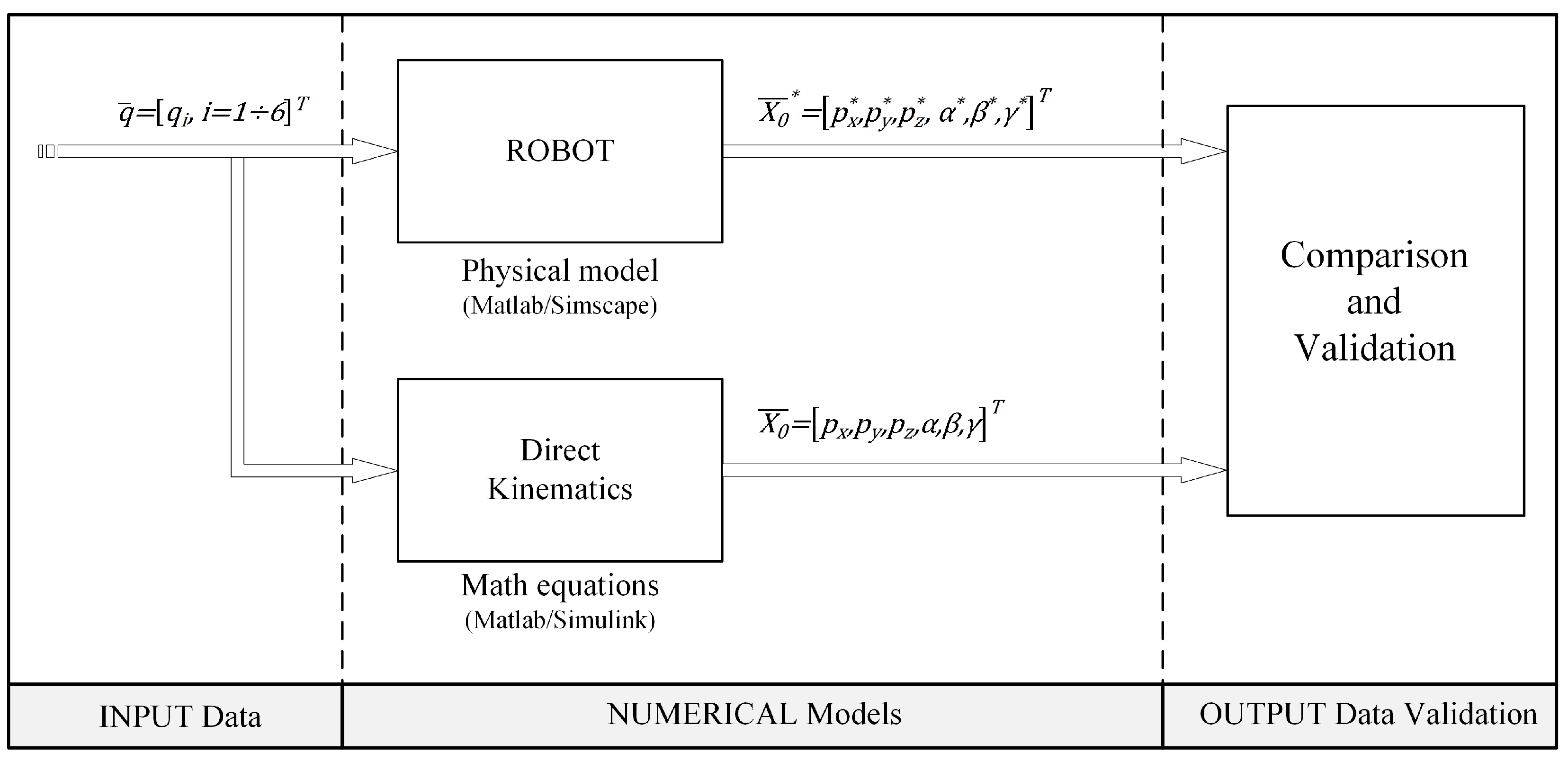
5.1. Method Description

For the validation of the dynamic model, a testing method is proposed, which involves the processing of two steps detailed below.

5.1.1. Validation of Direct Kinematics Model

In STEP 1, an auxiliary model of the robot TRTTR (Robot—Physical Model) is developed using a modeling scheme based on the “physical” interconnection of the robot’s component elements. Since the Robot—Physical Model is made in a specialized program (Matlab/Simulink/Simscape) according to the configuration of the TRTTR robot, it is considered that the result ( X 0 ¯ * ) provided by it can be evaluated as the true value of the end- effector displacement.
The direct kinematic model of the TRTTR robot allows the calculation of the displacements ( X 0 ¯ ) in the operational space when the displacements in the joint space q ¯ are known. It is important to test it because the validation of the dynamic model involves the use of the direct kinematic model. The direct kinematic model of TRTTR, according to [10], is:
X ¯ 0 = p x 6 p y 6 p z 6 α z β x γ z = s q 1 l 3 + v 2 + c q 1 s q 2 + s q 1 c q 2 · l 6 l 0 + v 1 + c q 1 l 3 + v 2 c q 1 c q 2 s q 1 s q 2 · l 6 l 1 + l 2 + l 4 v 3 l 5 q 1 0 q 2 ,
where p x 6 , p y 6 , p z 6 are the end-effector displacements and, α z , β x , γ z are Euler’s angles.
The validation scheme of the direct kinematic model is detailed in Figure 3. Both models (Direct Kinematic and Physical model) receive the joint displacements at the input and provide the end-effector displacement and orientation ( X 0 ¯ , X 0 ¯ * ) in the operational space at the output. Comparing the results allows the evaluation and validation of the tested model (DK model).

5.1.2. Validation of Dynamic Model (Lagrange Equations)

In STEP 2, the dynamic model of the robot (described by the Lagrange equations) is tested, Figure 4. The actuation torques τ ¯ are applied to the robot joints (as model input), respectively, the dynamic model provides the joint displacements q ¯ according to the robot dynamics. Then, the resulting displacements q ¯ are applied to the direct kinematic model (validated in STEP 1), which provides end-effector displacements ( X 0 ¯ ) in operational space (as outputs). The same actuation torques are applied to the physical model of the robot, which provides the end-effector displacement ( X 0 ¯ * ) in operational space and which will serve for comparison, analysis, and validation of the dynamic model. In addition, the physical model of the robot can also calculate joints displacements q ¯ , which can also be used as an auxiliary option for validating the dynamic model.

5.2. Numerical Results

To simplify the complexity of the numerical simulations, the models used by the proposed validation method are accompanied by the following simplifying assumptions: the choice of the origin of the local coordinate systems is made in the center of mass of the robot elements, the contribution of the centrifugal moments of inertia is ignored. These assumptions do not change the dynamic equations of the robot.
To implement the validation method, the Matlab/Simulink software was used, respectively, the following models were developed and implemented:
  • Robot—Physical Model: physical modeling of robot components with elements from the Matlab/Simulink/Simscape/MultiBody libraries;
  • Direct Kinematics model: math equations according to [10];
  • Dynamic model—Lagrange equations: Simulink implementation of the Lagrange Equations (17).
In order to perform the numerical simulations, the following model parameters were used: m 1 = 5   k g ; m 2 = 3   k g ; m 3 = 2   k g ; m 4 = 1   k g ; m 5 = 1   k g ; l 0 = 0.40   m ; l 1 = 0.49   m ;   l 2 = 0.60   m ; l 3 = 0.685   m ; l 4 = 0.20   m ; l 5 = 0.45   m ; l 6 = 0.15   m ; J Δ 1 2 = J Δ 1 3 = 0.1   k g · m 2 ; J Δ 2 4 = J Δ 2 5 = 0.1   k g · m 2 ; C 1 = 25   N / m / s ; C 2 = 30   N / r a d / s ; C 3 = 10   N / m / s ; C 4 = 1000   N / m / s ; C 5 = 10   N / r a d / s . The testing was performed based on the steps described above, respectively, the results were analyzed.

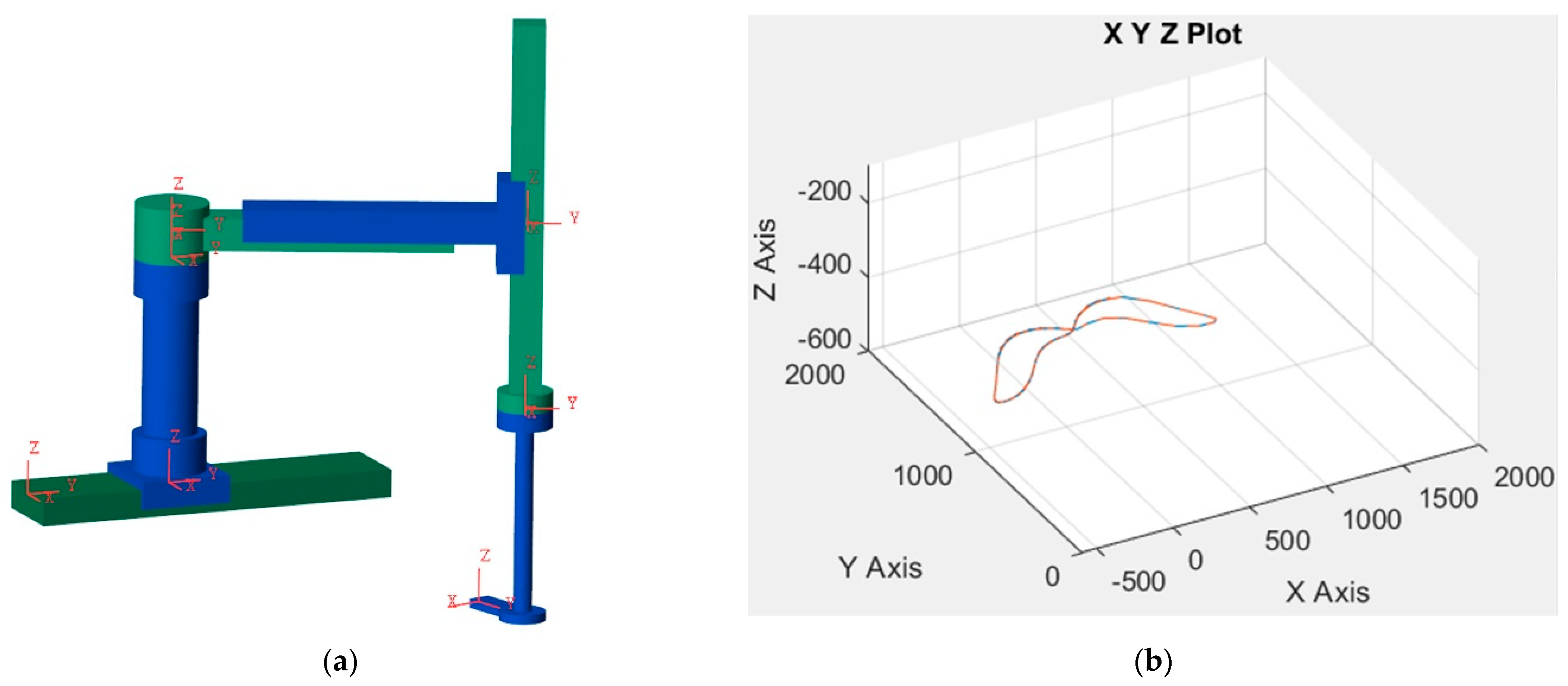
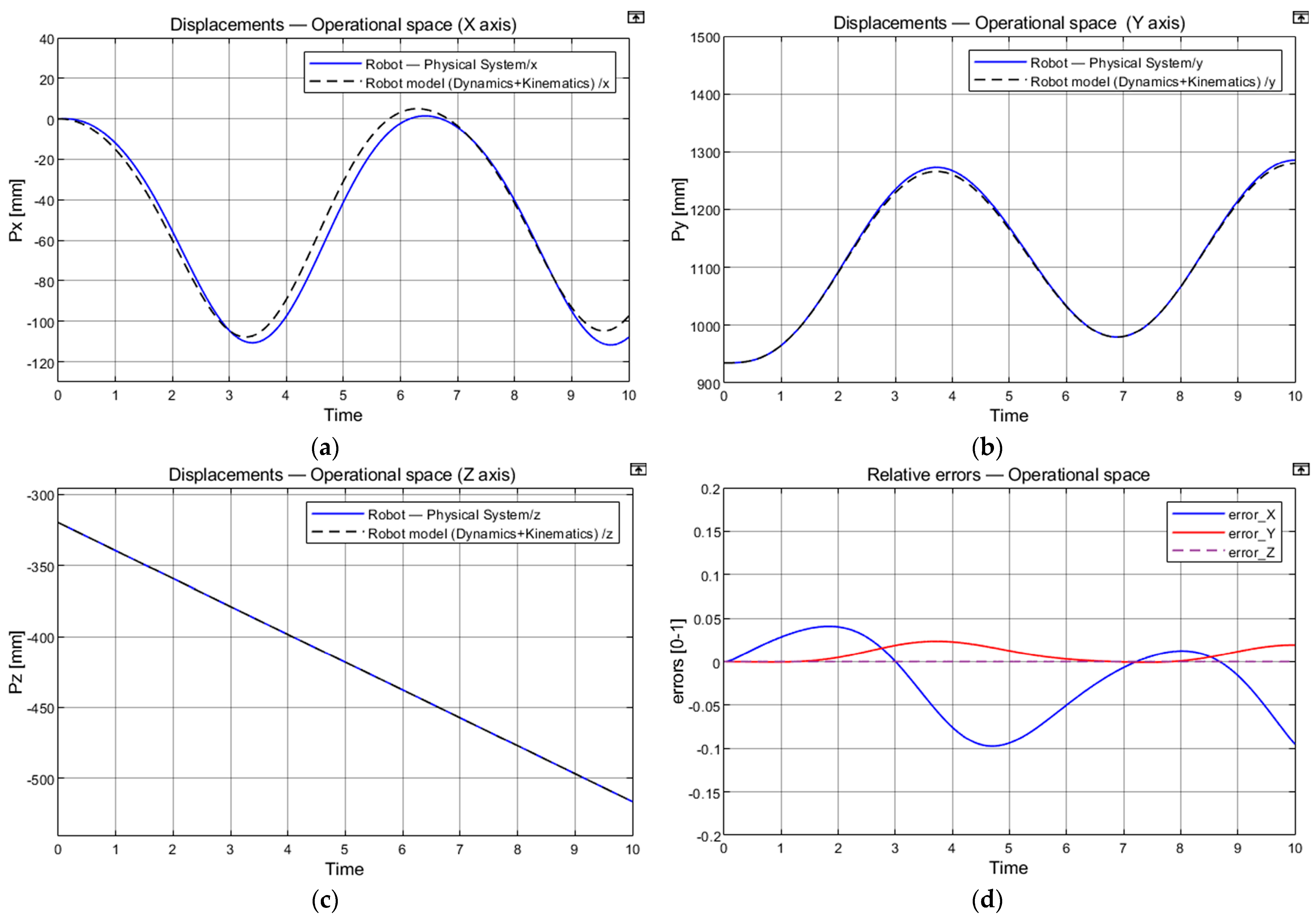
5.2.1. Validation of Direct Kinematic Model

The input data for STEP 1 are: v 1 = 200   sin t   m m ; q 1 = sin t   r a d ; v 2 = 100   sin 2 t   m m ; v 3 = 100   sin t   m m ; q 2 = sin 3 t   r a d ; t 0 ; 10   s and represents the simulation time.
According to Figure 3 in the test scheme, an imposed movement q ¯ was applied to the robot’s joints at the input in the form of sinusoidal displacements. After the simulations were performed, the following results were obtained, described comparatively in Figure 5.
Comparing the output variables ( X 0 ¯ , X 0 ¯ * ), the absolute errors are found to be less than 1.5 mm, respectively, the relative errors are below 0.1%. Consequently, the direct kinematic model is validated by numerical simulation and will be used in the second stage (STEP2) to validate the dynamic model in accordance with the test scheme related to STEP 2.

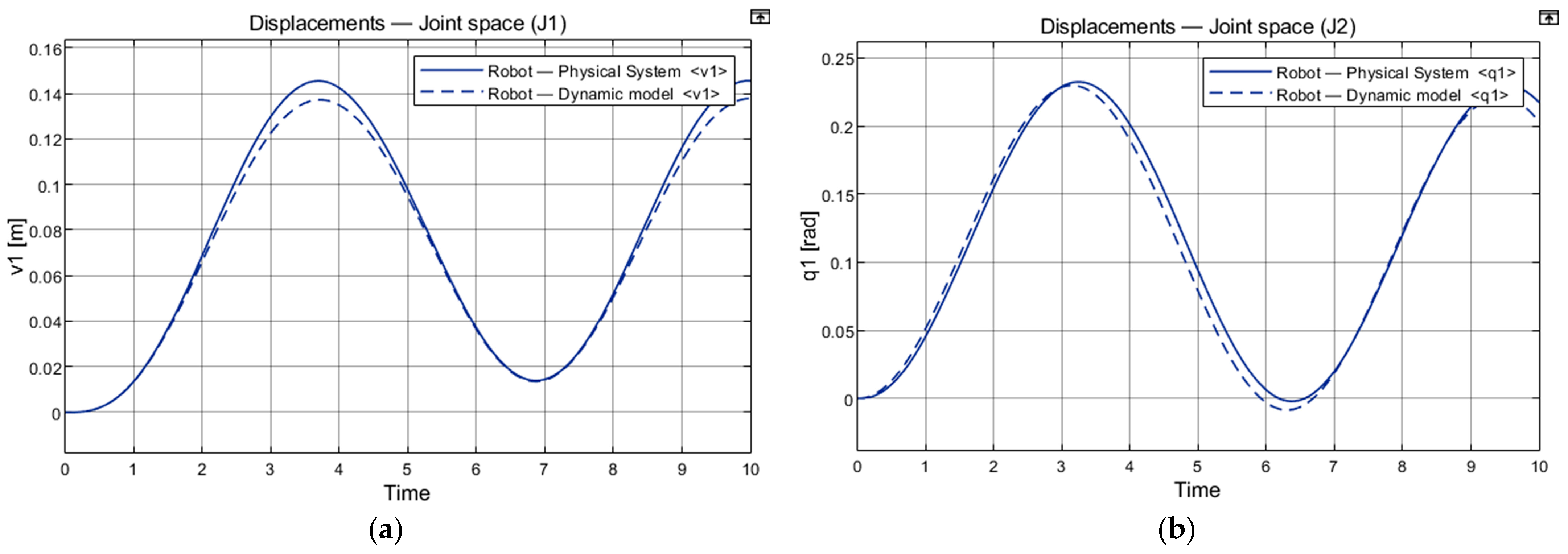
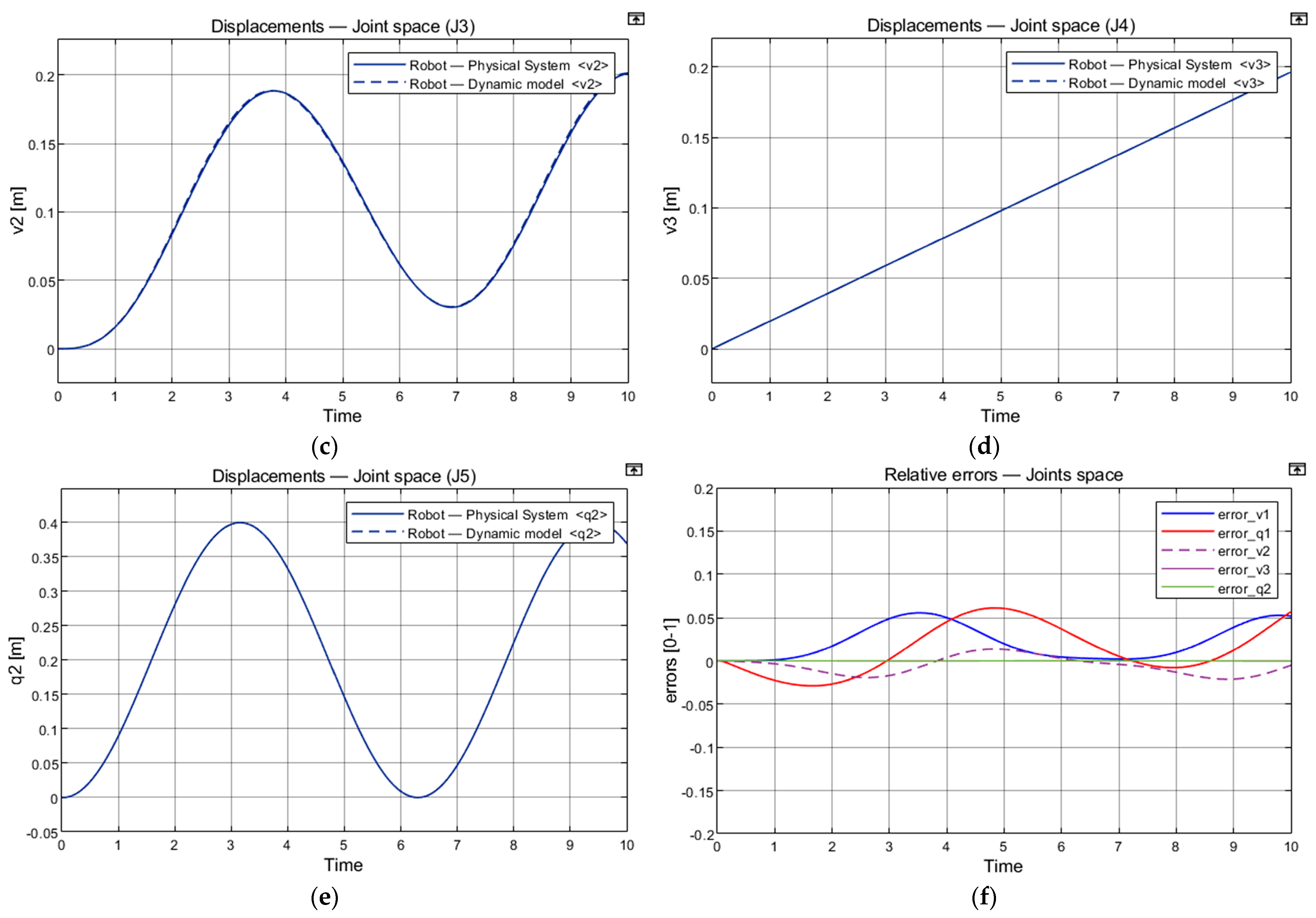
5.2.2. Validation of Dynamic Model

The input data for STEP 2 are: F 1 = 2   sin t   N ;   M 2 = 3.5   sin t   N · m ;   F 3 = sin t   N ;   F 4 = 0.1   sin t   N ;   M 5 = 2   sin t   N · m ;   t 0 ; 10   s .
According to Figure 4, the imposed torques τ ¯ were applied to the robot’s joints as inputs (sinusoidal signals), respectively, at the output of the models, the joints displacements q ¯ and end-effector displacement ( X 0 ¯ , X 0 ¯ * ) were collected and comparatively analyzed. The results are detailed comparatively in Figure 6 and Figure 7.
After the analysis of the output variables ( X 0 ¯ , X 0 ¯ * ) it is observed that the displacements calculated by the dynamic model (Lagrange equations) overlap with the displacements generated by the physical model, the relative errors being below 6%. Consequently, the numerical results validate the dynamic model according to the proposed test method and simplifying assumptions.

6. Driving Motors Selection of the Translation Modules

The proposed robot was designed for carrying out humanitarian demining operations, e.g., demining unexploded ordnance (UXO) and improvised explosive devices (IED). In order to carry out these types of tasks, it was necessary for the mechanical structure of the robot to be built mainly from translation modules. Thus, a precise and smooth extraction of the explosive fixed in the ground is ensured, respectively, the translational movements reduce the vibrations of the entire structure during operation, and the accidental triggering of the explosive charge is avoided. In this context, a dynamic-organological approach is presented that allows the calculation of the necessary drive moments of the motors, and the real drive motors of the translation modules can be selected. This approach only refers to the translation modules because the calculated motor torques must ensure the necessary power for the functioning of the modules to achieve the genistic task. Thus, oversizing the motors in terms of energy and dimensions is avoided.
The effective axial force Fa required to set the translation module MTB SIL in motion has the following equation [37,38]:
F a = F s b . F f ,
where: F s b . represents the axial force developed by the screw-ball transmission and Ff the friction force in the guideway.
The F s b . force has the following equation [11]:
F s b . = 2 · M s d 0 · t a n φ + a r c t a n k d b s i n θ ,
where d0 represents the diameter of the cylinder that holds the ball centers, φ is the dwell angle of the helix on the medium cylinder, k is the rolling friction coefficient, db represents the ball diameter, θ is the contact angle between the ball and the runway, Ms represents the torque at the screw-ball axle.
Denoting by Ps, ns the power and the angular speed of the screw-ball, the torque Ms has the following equation:
M s = 9550 · P s n s ,
P s = P m · η r .
In (22) η r represents the output of a pair of bearings, and Pm is the power developed by the DC motor that drives the movable system at the robotic base into motion. The angular speed of the screw-ball ns must fulfill the following inequality nsnm where with nm it was noted the angular speed of the driving shaft. Given the (21) and (22) and previous inequality, (20) becomes:
F s b . = 191 · 10 2 · P m · η r n m · d 0 · t a n φ + a r c t a n k d b s i n θ .
Having in view (19) and (23), the dynamic Equation (17), corresponding to the horizontal translation module 1 at the robotic base (MTB SIL), becomes:
i = 1 5 m i v ¨ 1 + i = 3 5 m i · cos q 1 v ¨ 2 i = 3 5 m i · sin q 1 l 3 + v 2 q ¨ 1 2 · i = 3 5 m i · sin q 1 q ˙ 1 v ˙ 2 i = 3 5 m i · cos q 1 l 3 + v 2 q ˙ 1 2 + C 1 v ˙ 1 = 191 · 10 2 · P m · η r n m · d 0 · t a n φ + a r c t a n k d b s i n θ F 3 sin q 1 F f .
The frictional force Ff has the following equation:
F f = i = 1 5 m i · g · μ ,
where g is the gravitational acceleration (g = 10 m/s2), and µ is the friction coefficient in the guides (standard value, µ = 0.02).
The dwell angle of the helix on the medium cylinder (φ) is calculated using the equation:
φ = a r c t a n g p h π · d 0 ,
where p h is the feed screw twist.
Thus, with (25) it was obtained the P m n m ratio:
i = 1 5 m i v ¨ 1 + i = 3 5 m i · cos q 1 v ¨ 2 i = 3 5 m i · sin q 1 l 3 + v 2 q ¨ 1 2 · i = 3 5 m i · sin q 1 q ˙ 1 v ˙ 2 i = 3 5 m i · cos q 1 l 3 + v 2 q ˙ 1 2 + C 1 v ˙ 1 + F 3 sin q 1 + F f · d 0 · t a n φ + a r c t a n k d b s i n θ 191 · 10 2 · P m · η r = P m n m .
With (17), the motor drive moment can be calculated, and the drive motor of the MTB SIL translation module selected, respectively.
Given the construction of the horizontal translation module, MTV SIL can be determined as the expression of the driving force F3 depending on motor moments, gear ratios, outputs, the geometry of the screw-ball nut transmission, as well as on the used guide-ways type. According to relations (19 ÷ 21), the power Ps can be determined as follows:
P s = P m · η r · η m ,
denoting by η r , η m the output of a pair of bearings and of the worm gear, respectively, and by Pm, the necessary power developed by the DC motor that drives the horizontal translation movable system in the robotic arm into motion.
The ns rotation speed of the screw must fulfill the following inequality:
n s n m .
Hence, the rotation speed of the screw-ball has the following expression:
n s = n m i m ,
where im stands for the worm gear ratio.
Given (19), (21), (28), (29), and (30), relation (20) become:
F s b . = 191 · 1 0 2 · P m · η r · η m · i m n m · d 0 · t g φ + a r c t g k d b · sin θ .
Given (19), (31), the dynamic equation represented by (17), corresponding to the horizontal translation module in the robotic arm (MTV SIL), becomes:
i = 3 5 m i v ¨ 2 + i = 3 5 m i cos q 1 v ¨ 1 i = 3 5 m i l 3 + v 2 q ˙ 1 2 + C 3 v ˙ 2 = 191 · 1 0 2 · P m · η r · η m · i m n m · d 0 · t g φ + a r c t g k d b · sin θ F f .
The frictional force, Ff, is calculated using the following relation:
F f = i = 3 5 m i · g · μ .
From the (33), we can obtain an expression of the P m n m ratio:
i = 3 5 m i v ¨ 2 + i = 3 5 m i cos q 1 v ¨ 1 i = 3 5 m i l 3 + v 2 q ˙ 1 2 + C 3 v ˙ 2 + F f · d 0 · t g φ + a r c t g k d b · sin θ 191 · 1 0 2 · η r · η m · i m = P m n m .
With (34), the motor driving moment can be calculated, and the driving motor of the MTV SIL translation module selected.
Given the construction of the vertical translation module of the TRTTR modular robotic arm (of the end-effector) (MT SIL), the expression of the driving force F4 depending on motor moments, gear ratios, outputs, the geometry of the screw-ball nut transmission, as well as on the type of guideways used, can be determined. According to relations (19), (20), and (21), the power Ps is determined as follows:
P s = P m · η r · η c .
In (35) was noted with ηr the output of a pair of bearings, ηc the output of the spur-gear drive and Pm the power developed by the DC motor that drives the translation movable system in the robotic arm vertical structure into motion.
Given the (30), (35), and (19), the relation (20) become:
F s b . = 191 · 1 0 2 · P m · η r · η c · i c n m · d 0 · t g ( φ + a r c t g k d b · sin θ ) .
Given the (19), (30), and (36), the dynamic equation represented by (17), corresponding to the vertical translation module in the robotic arm (MT SIL), become:
i = 4 5 m i v ¨ 3 + C 4 v ˙ 3 = 191 · 1 0 2 · P m · η r · η c i c n m · d 0 · t g φ + a r c t g k d b · sin θ + P 4 + P 5 F f .
For this case, the frictional force is calculated using the following relation:
F f = ( i = 4 5 m i ) · g · μ .
From (26) and (38), we can obtain an expression of the P m n m ratio:
i = 4 5 m i v ¨ 3 + C 4 v ˙ 3 P 4 P 5 + F f · d 0 · tan φ + a r c t g k d b · sin θ 191 · 10 2 · η r · η c · i c = P m n m .
With (39), we can calculate the motor driving moment, and the driving motor of the MT SIL translation module can be selected.
For each translation modulus of the TRTTR robot, using the dynamic and design equations, the motor driving moment (Mm_theoretical) was determined. After performing the calculations, the following results were obtained (Table 1). With the theoretical value of the driving moment (Mm_theoretical), for each translation modulus, the real driving motor (Mm_selected) and servomotor from the QMot QBL4208 family catalog [39] (Table 2) were easily selected. The driving motors were chosen to fulfill the condition of reduced dimensions and minimal energy consumption imposed by the design criteria.
For theoretical calculus, the following input data regarding the constructive and functional parameters of the serial-tracked robot were taken into account [40]: m 1 = 41   k g ; m 2 = 44.75   k g ; m 3 = 43   k g ; m 4 = 30.41   k g ; m 5 = 7.72   k g ; l 3 = 0.04   m ; m o b j e c t = 3   k g ; p h = 0.008   m ; d 0 = 0.03   m ; k = 0.00001 m; db = 0.0055 m; θ = 45°; ηr = 0.995; q 1 = π / 4   r a d ; v 2 = 0.25   m ; v ¨ 2 = 1.5   m / s 2 ; q ˙ 1 = 0.75   r a d / s ; q ¨ 1 = 0.25   m / s 2 ; v ˙ 1 = 0.30   m / s ; v ¨ 1 = 1   m / s 2 ; v ˙ 2 = 0.4   m / s ; P4 = 421.47 N; P5 = 438.5 N. It is specified that the mass values of the robot modules include the mass of the end-effector.

7. Conclusions

The development of structures and robots for their use in military purposes, such as humanitarian demining, was necessary to protect the lives of civilians and also of EOD forces.
The paper proposes an original serial-tracked robot for humanitarian demining, subject to patent RO132301, B1/2021. The tracked robot presented was designed to solve technical issues such as flexibility by carrying out several military operations due to its modular construction, autonomy by using electric motors powered by solar panels with photovoltaic cells minimizing environmental pollution and energy consumption, reducing assembling and maintenance time due to its compact mechanical structure and modular construction. Other important advantages are the use of materials and components resistant to dangerous environments preventing the partial or total destruction of the vital mechanical elements in operation, a storage compartment for the explosives necessary for humanitarian demining, and the wireless communication between the human operator and the robot.
Dynamic modeling using Lagrange’s formalism of the TRTTR serial structure of the tracked robot was performed to obtain the kinetic energy of each modulus and differential motion equations of the robot, respectively. A two-step method is proposed for the numerical validation of the dynamic model. The numerical results validate the dynamic model (Lagrange equations of motion), recorded relative errors (joints displacements) being about 6%, part of them related to the proposed validation method and simplifying assumptions.
An approach to calculate the motor moments required for the drive motors selection of the robot’s translation modules was presented, considering the dynamic motor forces and the Pm/nm ratio resulting from the design calculations. This approach has the advantage of properly sizing and selecting electric motors to minimize electricity consumption. The theoretical values of the driving motors moments of each translation module of the serial-tracked robot are given. Technical specifications of the selected driving motors for each translation module are also presented.
Future work will address practical implementation and land testing of the serial-tracked robot in demining operations.

8. Patents

Petrişor, S.M., Bârsan, Gh., Simion, M., Virca, I., Moşteanu, D.E., “Tracked robot destined for humanitarian demining operations”, Invention Patent No. RO 132301B1/30.12.2021, no. C.B.I.: a 2017 00562, International Class: F41H11/16, Publication no.: 132301 A0, Deposit date: 10.08.2017, Published C.B.I.: 29/12/2017//12/2017, Published B.I.: 30/12/2021//12/2021, Holder: “Nicolae Bălcescu” Land Forces Academy, Sibiu, C.B.I.: Official Bulletin of Industrial Property, Patent Section, Nr. 12/2017, ISSN 2065-2100, p 18, B.I.: Official Bulletin of Industrial Property, Patent Section, No. 12/2021, ISSN 2065-2100, p. 90, OSIM Bucharest.

Author Contributions

Conceptualization, S.M.P. and M.S.; methodology, M.S. and S.M.P.; software, O.H.; validation, O.H. and M.S.; formal analysis, S.M.P.; investigation, S.M.P. and M.S.; resources, S.M.P.; writing—original draft preparation, M.S.; writing—review and editing, M.S. and S.M.P.; visualization, M.S. and S.M.P.; supervision, S.M.P. and G.B.; project administration, S.M.P. and G.B.; funding acquisition, S.M.P. and G.B. All authors have read and agreed to the published version of the manuscript.

Funding

This research was funded by the research project of the Ministry of National Defense of Romania, Contract no. 63/2020-2022, type PSCD, acronym AVANGARDROBO, title: Practical realization of a TRL5 type technological demonstrator of a tracked mini-robot destinated for engineer missions.

Data Availability Statement

Not applicable.

Acknowledgments

The research highlighted in this paper represents the dissemination of scientific activities undertaken and funded through the research project of the Ministry of National Defense of Romania, Contract no. 63/2020-2020, PSCD type, acronym AVANGARDROBO, title: Practical realization of a TRL5 type technological demonstrator of a tracked mini-robot destinated for engineer missions.

Conflicts of Interest

The authors declare no conflict of interest.

References

  1. Portugal, D.; Cabrita, G.; Gouveia, B.D.; Santos, D.C.; Prado, J.A. RETRACTED: An autonomous all terrain robotic system for field demining missions. Robot. Auton. Syst. 2015, 70, 126–144. [Google Scholar] [CrossRef]
  2. Rachkov, M.Y.; Marques, L.; De Almeida, A.T. Multisensor Demining Robot. Auton. Robot. 2005, 18, 275–291. [Google Scholar] [CrossRef]
  3. Available online: https://reliefweb.int/report/colombia/colombia-antipersonnel-mines-and-explosive-remnants-war (accessed on 7 January 2023).
  4. Debenest, P.; Fukushima, E.F.; Tojo, Y.; Hirose, S. A New Approach to Humanitarian Demining Part 1: Mobile Platform for Operation on Unstructured Terrain. Auton. Robot. 2005, 18, 303–321. [Google Scholar] [CrossRef]
  5. Available online: https://reliefweb.int/report/mali/mali-increase-civilian-victims-explosive-devices-dg-echo-unmas-echo-daily-flash-14-october-2022 (accessed on 7 January 2023).
  6. JP 3-42 Joint Explosive Ordnance Disposal. Available online: http://www.jcs.mill (accessed on 16 January 2022).
  7. Gao, F.; Zhang, H.; Li, Y.; Deng, W. Research on target recognition and path planning for EOD robot. Int. J. Comput. Appl. Technol. 2018, 57, 325–333. [Google Scholar] [CrossRef]
  8. Fang, W. Design of Obstacle Avoidance Control System for Mobile Robot Based on Vision. In Cyber Security Intelligence and Analytics: The 4th International Conference on Cyber Security Intelligence and Analytics (CSIA 2022); Springer: Cham, Switzerland, 2022; pp. 1005–1011. [Google Scholar] [CrossRef]
  9. Petrişor, S.M.; Simion, M. Example of good practices regarding the organological construction of a robotized technological product for humanitarian engineering operations. Acta Tech. Napoc. Ser. Appl. Math. Mech. Eng. 2021, 64, 395–402. Available online: https://atna-mam.utcluj.ro/index.php/Acta/article/view/1643 (accessed on 14 November 2021).
  10. Petrişor, S.M.; Simion, M. Aspects Regarding the Elaboration of the Geometric, Kinematic and Organological Study of a Robotic Technological Product “Humanitarian PetSim Robot” Used as an Avant-Garde Element of the Human Factor in High Risk Areas. In Intelligent Systems and Applications: Proceedings of the 2020 Intelligent Systems Conference (IntelliSys); Springer: Berlin/Heidelberg, Germany, 2020; pp. 322–334. [Google Scholar] [CrossRef]
  11. Jaradat, M.A.; Bani-Salim, M.; Awad, F. A Highly-Maneuverable Demining Autonomous Robot: An Over-Actuated Design. J. Intell. Robot. Syst. 2018, 90, 65–80. [Google Scholar] [CrossRef]
  12. de Cubber, G.; Balta, H.; Lietart, C. Teodor: A Semi-Autonomous Search and Rescue and Demining Robot. Appl. Mech. Mater. 2014, 658, 599–605. [Google Scholar] [CrossRef]
  13. Hemapala, M.; Belotti, V.; Michelini, R.; Razzoli, R. Humanitarian demining: Path planning and remote robotic sweeping. Ind. Robot. Int. J. Robot. Res. Appl. 2009, 36, 146–156. [Google Scholar] [CrossRef]
  14. Tojo, Y.; Debenest, P.; Fukushima, E.F.; Hirose, S. Robotic System for Humanitarian Demining Development of Weight-Compensated Pantograph Manipulator. In Proceedings of the 2004 IEEE International Conference on Robotics and Automation, New Orleans, LA, USA, 26 April–1 May 2004; pp. 2025–2030. [Google Scholar]
  15. Debenest, P.; Fukushima, E.F.; Tojo, Y.; Hirose, S. A New Approach to Humanitarian Demining Part 2: Development and Analysis of Pantographic Manipulator. Auton. Robot. 2005, 18, 323–336. [Google Scholar] [CrossRef]
  16. Hemapala, K.; Razzoli, R.P. Design and Development of a Landmines Removal Robot. Int. J. Adv. Robot. Syst. 2012, 9, 5. [Google Scholar] [CrossRef]
  17. Mori, Y.; Takayama, K.; Adachi, T.; Omote, S.; Nakamura, T. Feasibility Study on an Excavation-Type Demining Robot. Auton. Robot. 2005, 18, 263–274. [Google Scholar] [CrossRef]
  18. Montes, H.; Mena, L.; Fernández, R.; Sarria, J.; de Santos, P.G.; Armada, M. Hexapod robot for humanitarian demining. In Proceedings of the 8th IARP Workshop on Robotics for Risky Environments, Escola Naval da Marinha Portuguesa, Lisboa, Portugal, 28–29 January 2015; Available online: http://hdl.handle.net/10261/111656 (accessed on 14 October 2022).
  19. Colon, E.; De Cubber, G.; Ping, H.; Habumuremyi, J.-C.; Sahli, H.; Baudoin, Y. Integrated Robotic systems for Humanitarian Demining. Int. J. Adv. Robot. Syst. 2007, 4, 24. [Google Scholar] [CrossRef]
  20. Baudoin, Y.; Acheroy, M.; Piette, M.; Salmon, J.P. Humanitarian Demining and Robotics. J. Mine Action 1999, 3, 1–9. Available online: https://commons.lib.jmu.edu/cisr-journal/vol3/iss2/ (accessed on 14 October 2022).
  21. Kang, S.P.; Choi, J.; Suh, S.-B.; Kang, S. Design of mine detection robot for Korean mine field. In 2010 IEEE Workshop on Advanced Robotics and its Social Impacts; IEEE: Piscataway, NJ, USA, 2010; pp. 53–56. [Google Scholar] [CrossRef]
  22. Havlík, S.; Licko, P. Humanitarian Demining: The Challenge for Robotic Research. J. Humanit. Demining 1998, 2, 2. [Google Scholar]
  23. Colon, E.; Hong, P.; Habumuremyi, J.-C.; Doroftei, I.; Baudoin, Y.; Shali, H.; Milojevic, D.; Weemaels, J. An integrated robotic system for antipersonnel mines detection. Control Eng. Pract. 2002, 10, 1283–1291. [Google Scholar] [CrossRef]
  24. Habib, M.K. Service Robots and Humanitarian Demining, Mobile Robots Towards New Applications; Lazinica, A., Ed.; I-Tech Education and Publishing: Rijeka, Croatia, 2006; pp. 449–480. ISBN 978-3-86611-314-5. [Google Scholar] [CrossRef]
  25. Habib, M.K. Humanitarian Demining: The Problem, Difficulties, Priorities, Demining Technology and the Challenge for Robotics, Humanitarian Demining: Innovative Solutions and the Challenges of Technology; Habib, M.K., Ed.; I-Tech Education and Publishing: Vienna, Austria, 2008; p. 392. ISBN 978-3-902613-11-0. [Google Scholar]
  26. Kopacek, P. Robots for Humanitarian Demining. In Advances in Automatic Control; The Springer International Series in Engineering and Computer Science; Voicu, M., Ed.; Springer: Boston, MA, USA, 2004; Volume 754. [Google Scholar]
  27. Santana, P.F.; Barata, J.; Correia, L. Sustainable Robots for Humanitarian Demining. Int. J. Adv. Robot. Syst. 2007, 4, 207–218. [Google Scholar] [CrossRef]
  28. Gonzalez de Santos, P.; Garcia, E.; Cobano, J.A.; Guardabrazo, T. Using Walking Robots for Humanitarian Demining Tasks. In Proceedings of the 35th International Symposium on Robotics, Paris, France, 23–26 March 2004. [Google Scholar]
  29. Swett, B.A.; Hahn, E.N.; Llorens, A.J. Designing Robots for the Battlefield: State of the Art, In Robotics, AI, and Humanity; von Braun, J., Archer, S.M., Reichberg, G.M., Sánchez Sorondo, M., Eds.; Springer: Cham, Switzerland, 2021. [Google Scholar] [CrossRef]
  30. Petrişor, S.M. Industrial Robots Used in Special Applications, The ”Nicolae Bălcescu”; Land Forces Academy Publishing House: Sibiu, Romania, 2010. [Google Scholar]
  31. Li, D.-Q.; Hong, H.-J.; Jiang, X.-L. Dynamics Modeling, Control System Design and Simulation of Manipulator Based on Lagrange Equation. In Mechanism and Machine Science. ASIAN MMS CCMMS 2016, Lecture Notes in Electrical Engineering; Springer: Berlin/Heidelberg, Germany, 2017; Volume 408, pp. 1129–1141. [Google Scholar] [CrossRef]
  32. Ispas, V. Manipulators and Industrial Robots; Didactic and Pedagogic Publishing House: Bucharest, Romania, 2004. [Google Scholar]
  33. Negrean, I. Kinematics and Dynamics of Robots: Modeling—Experiment—Precision; Didactic and Pedagogic Publishing House: Bucharest, Romania, 1999. [Google Scholar]
  34. Drimer, D.; Oprean, A.; Dorin, A.; Alexandrescu, M.; Paris, A.; Panaitopol, N.; Udrea, C.; Crişan, I. Industrial Robots and Manipulators; Technical Publishing House: Bucharest, Romania, 1985. [Google Scholar]
  35. Petrişor, S.M.; Bârsan, G. Aspects on the design, implementation, and simulation of a tracked mini robot destined for special applications in theatres of operations. In Proceedings of the Sixth International Conference on Machine Vision (ICMV 2013), London, UK, 16–17 November 2013. [Google Scholar] [CrossRef]
  36. Chircor, M.; Curaj, A. Kinematic, Dynamic Elements and Trajectory Planning of Industrial Robots; The Publishing House of the Romanian Academy: Bucharest, Romania, 2001. [Google Scholar]
  37. Chişiu, A.; Matieşan, D.; Mãdãrãşan, T.; Pop, D. Machine Parts; Didactic and Pedagogic Publishing House Bucharest: Bucharest, Romania, 1981. [Google Scholar]
  38. Petrişor, S.M.; Bârsan, G. Aspects on the Calculus and Construction of Translation Modules in the Mechanical Structure of an Industrial Robot Possessing Four Degrees of Freedom. Appl. Mech. Mater. 2013, 390, 166–171. [Google Scholar] [CrossRef]
  39. Available online: https://www.directindustry.com/prod/trinamic-motion-control-gmbh-co-kg/product-60190-687513.html (accessed on 7 January 2023).
  40. STAS 6012-82, General Purpose Reducers. Transmission Reports. Available online: https://bjiasi.ebibliophil.ro/mon/stas-6012-82-reductoare-de-turatie-rapoarte-de-transmitere-b837rnnx/ (accessed on 7 January 2023).
Figure 1. Tracked mobile robot—CAD model [9,10].
Machines 11 00548 g001
Figure 2. The kinematic diagram of the TRTTR modular serial tracked robot [9]. The movements in the kinematic joints are highlighted.
Machines 11 00548 g002
Figure 3. Direct Kinematic model validation (STEP 1).
Machines 11 00548 g003
Figure 4. Dynamic model validation (STEP 2).
Machines 11 00548 g004
Figure 5. Validation of direct kinematics model. Numerical results: (a) Robot—Physical Model; (b) 3D end-effector displacements in operational space; (c) Px, end-effector displacement in operational space (X axis); (d) Py, end-effector displacement in operational space (Y axis); (e) Pz, end-effector displacement in operational space (Z axis); (f) end-effector absolute errors about X, Y, and Z axis.
Machines 11 00548 g005aMachines 11 00548 g005b
Figure 6. Validation of dynamic model. Numerical results: (a) Px, end-effector displacement in operational space (X axis); (b) Py, end-effector displacement in operational space (Y axis); (c) Pz, end-effector displacement in operational space (Z axis); (d) end-effector relative errors about X, Y, and Z axis.
Machines 11 00548 g006
Figure 7. Validation of dynamic model. Numerical results: (a) v1, joint J1 displacement; (b) q1, joint J2 displacement; (c) v2, joint J3 displacement; (d) v3, joint J4 displacement; (e) q2, joint J5 displacement; (f) Joint displacements relative errors.
Machines 11 00548 g007aMachines 11 00548 g007b
Table 1. Technical specifications of the driving motors obtained by theoretical calculus.
ModuleFrictional ForceDwell AnglePower Driving Motor andTheoretical Driving
TypeFfφAngular SpeedMoment
RatioMm_theoretical
Pm/nm
[N][°][kW·min/rot][N·m]
MTB SIL33.3674.8521.65421·10−31.93
MTV SIL16.2264.8520.1253·10−30.10
MT SIL7.6264.8520.02385·10−30.35
Table 2. Parameters of the selected motors and type of servomotors.
ModuleSelectedServo-Rotation SpeedDriving PowerMass
TypeDriving Motor Motor TypenmPm
Moment
Mm_selected
[N·m] [rpm][kW][kg]
MTB SIL2.15QBL17E40-01D-05RO50001.23.3
MTV SIL0.18QBL4208-81-04-01940000.071.5
MT SIL0.56QBL4208-81-04-01940000.081.8
Disclaimer/Publisher’s Note: The statements, opinions and data contained in all publications are solely those of the individual author(s) and contributor(s) and not of MDPI and/or the editor(s). MDPI and/or the editor(s) disclaim responsibility for any injury to people or property resulting from any ideas, methods, instructions or products referred to in the content.

