1. Introduction
Tooth Coil Winding Axial Flux Permanent Magnet (TCW-AFPM) machines are an attractive solution in low-speed applications owing to their high power/weight ratio, high aspect ratio, and high efficiency, being a suitable option in vehicular propulsion, more electric aircraft and direct drive wind power generation [
1,
2,
3,
4,
5,
6]. These machines are characterized by a disk-shaped structure in which the coils are wound around a single tooth; the flux produced by the magnets crosses the airgap in the same direction as the shaft. Several studies have been published on axial flux machines with other types of windings showing that there are often difficulties in finding suitable space for the long and bulky inner end-windings, presenting a reason why TCW are usually adopted for these machines [
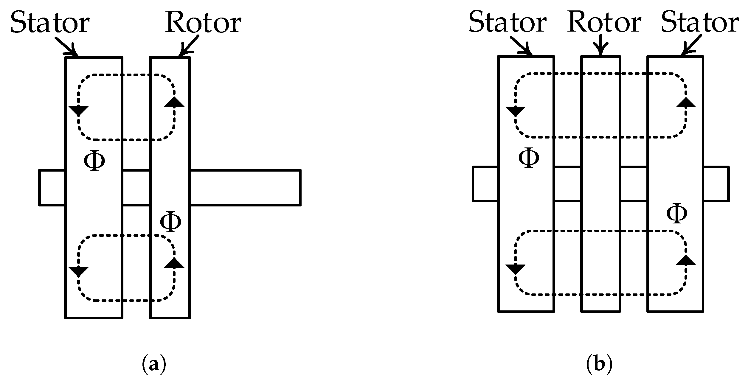
7]. AFPM machines can be classified depending on the number of stators and rotors, as exemplified in
Figure 1: one-stator one rotor topology (
Figure 1a) is characterized by a simple structure and is generally intended for low and medium power, whereas multiple rotors and multiple stators (
Figure 1b) are used to increase the output power of the machine and to reduce the mechanical stress on the bearings.
Two-stator one-rotor AFPM machines are widely studied given their inherent mechanic stability and comparative advantages. Moreover, if the supporting structure of permanent magnets is manufactured with non-conductive and non-ferromagnetic materials, eddy current losses can be eliminated and leakage flux produced by the magnets can be significantly reduced [
7,
8,
9].
Due to the absence of ferromagnetic material, in AFPMs with ironless rotors, the magnets are free to move in any direction, therefore precise fabrication of the supporting structure is required in order to fix the PMs in the correct position. However, dimensional tolerances and material imperfections which are inherent to the manufacturing process can appear during the machine construction causing the displacement of the magnets and affecting its output performance indices [
10].
In the last decade, some papers have approached the influence that manufacturing tolerances and material imperfections have on the performance of state-of-the-art topologies. It has been demonstrated that dimensional tolerances affect the cogging torque of radial-flux PM machines either by increasing the amplitude of the current harmonics or by adding new harmonic components [
11,
12]. Similar effects are produced by magnetization faults or magnetization imperfections [
13]. The analysis of the affected performance indices is often carried out by considering specific faults and cases, although there have been some efforts to generalize the findings through statistical methods [
14,
15].
In [
14], an analysis of manufacturing tolerances affecting a radial flux permanent magnet (RFPM) machine was developed. It was found that positional deviations of PMs in the circumferential direction raise the likelihood of obtaining a high cogging torque magnitude (higher than the faultless design). A similar analysis was carried out in [
15], which relied on an analytical model to evaluate several imperfections such as remanence, recoil permeability, magnet dimensions, and magnet and slot displacement deviations. The authors further stated that it is unfeasible to accurately predict the cogging torque solely by analyzing an idealized design.
In this regard, AFPM machines have been also studied, but most of the research articles focus on analyzing the effect of rotor and stator misalignments, static and dynamic eccentricity, and magnet shape selection [
16,
17,
18,
19,
20,
21]. The analysis of a double-rotor one-stator TCW-AFPM machine for wind power generation was presented in [
16]. Tilt and axial offset of the rotor discs were subjected to tolerance analysis, and both analytical and finite element (FE) models were used for this purpose. The authors stated that the studied imperfections produce a bending torque of the stator structure and can increase the ripple torque. A similar analysis is presented in [
17] for a double-stator one-rotor TCW-AFPM machine. Using quasi-3D FE simulations, it was found that the tilt of the rotor structure can increase the peak value and modify the wave-form period of cogging torque. A one-stator one-rotor AFPM machine was analyzed in [
18] by means of FE simulations, whereas a systematic method to experimentally measure the effect of tilt and axial offset was presented in [
19].
Although these papers provide relevant information regarding assembly imperfections of AFPM machines, several constructive parameters have not been further investigated. Moreover, the effect of the combination of several different faults on sensible performance indices of AFPM machines has not been covered in the technical literature so far. Assessing the effect of multiple combinations of faults on AFPM machines is not trivial. In order to have a precise estimation of sensible performance indices of an AFPM machine in the presence of several faults, 3-D FE simulations are required. However, full 3-D simulations are very time-consuming making their use prohibitive in most cases of tolerance analysis, which is critical in the case of axial flux machines which do not have planar symmetry. Analytical estimations may reduce the computation time, but their accuracy depends on the considered assumptions and simplifications. Very accurate analytical models based on Maxwell’s equations and conformal mapping can be used to analyze mechanical tolerances in AFPM machines [
20], but these approaches are difficult to implement on machines with complex geometries. Another alternative is to use a combination between FE evaluations and the superposition principle [
22,
23]. This method may provide acceptable computation time and accuracy, as preliminarily assessed in [
24].
This paper aims to provide a statistical analysis of the impact of several dimensional and material uncertainties on the cogging torque and electromagnetic torque developed by AFPM machines. An efficient superposition method (SM) is proposed to estimate the torque waveforms, which is validated through 3-D FE simulations. By using the proposed method, it is possible to evaluate different values of tolerances within a pre-established range, with relatively low computational effort. The proposed research is meant to be useful in the assessment of the sensitivity of AFPM machines when subject to dimensional tolerances. The superposition method described in this paper can be used directly in the design stage of AFPM machines, or to be included in their optimization since it evaluates the sensitiveness of a final design. The remainder of this paper is organized as follows. In
Section 2, the topology under study is described, and relevant parameters of the stator and rotor are presented. In
Section 3, a set of 3-D FE simulations are performed in order to evaluate dimensional and material tolerances and their effect on cogging torque and the rated torque of the machine. In
Section 4, a superposition technique is presented and used to develop a statistical analysis of relevant imperfections considering typical values of dimensional tolerances and magnet properties. Concluding remarks are provided in
Section 5.
2. Selected Topology and Studied Faults
A two-stator one-rotor TCW-AFPM machine is considered for the tolerance analysis, which is depicted in
Figure 2.
Each stator has 12 slots and is manufactured in a coiled M400-50A magnetic steel band. A TCW double-layer winding with rectangular conductors is considered for the stator coils which has some advantages over round conductors such as better filling factor, power density and lower power losses. The rotor is made of a non-magnetic and non-conducting material (polyamide-6 and fiberglass) with 10 embedded PMs. The magnets of the machine are made of a strong rare-earth samarium cobalt (Sr-Cb) 2:17 grade. Each PM is divided into 10 segments which are arranged into two layers reducing eddy current losses. The main dimensions and prototype data without dimensional or material imperfections are presented in
Table 1.
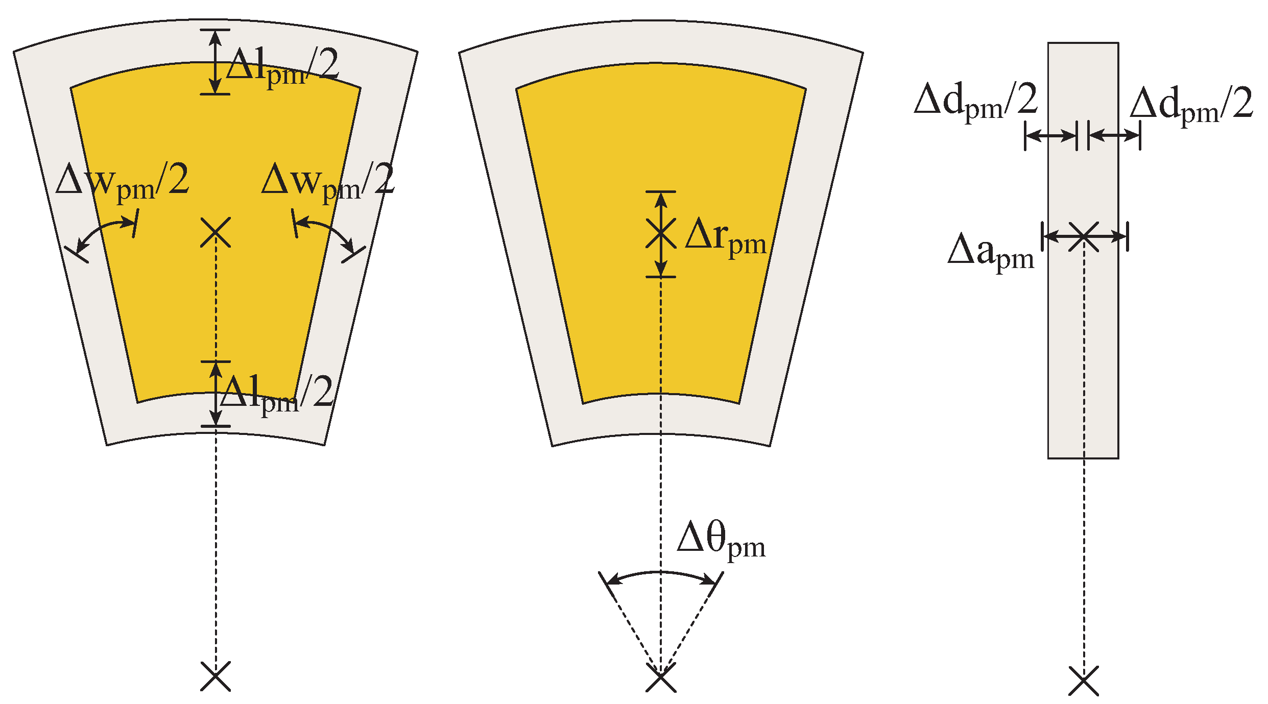
In this work, seven different types of faults can affect the magnets. These are: angular displacement (
), radial displacement (
), axial displacement (
), width variation (
), length variation (
), depth variation (
) and remanence variation (
).
Figure 3 schematizes each one of these faults.
The 3-D CAD model used for evaluating the AFPM machine is presented in
Figure 4. A dense mesh was considered in the airgap area and magnets, which resulted into precise results. According to the mesh feedback tool, the considered mesh contains 68.9% excellent-quality elements, 29.1% good-quality elements, 2% average-quality elements and no elements of below average or poor quality. Magnetostatic simulations were conducted when evaluating the cogging torque of the machine, and transient magnetic simulations were considered for the assessment of electromagnetic torque. The whole machine was modeled and evaluated since dimensional tolerances break the periodicity of the machine.
3. Preliminary Sensitivity Analysis
In order to identify the tolerances that have the most significant impact on the performance of AFPMSM, a preliminary analysis is developed. The cogging torque and the rated torque are evaluated by means of 3-D FE simulations when typical and magnified tolerances are assigned to a single PM. The different types of faults are evaluated separately so as to estimate the effect that each fault may produce on the performance indices of the machine.
To standardize the comparison of the impact of each fault type, a single magnet (referred to hereafter as dummy magnet) can have dimensional deviations of , or mm. Since the typical tolerance of laser cutting is 0.1 mm, this means that each magnet can present one, two or five times the typical dimensional deviation value. In turn, the dummy magnet can have remanence deviations of , and .
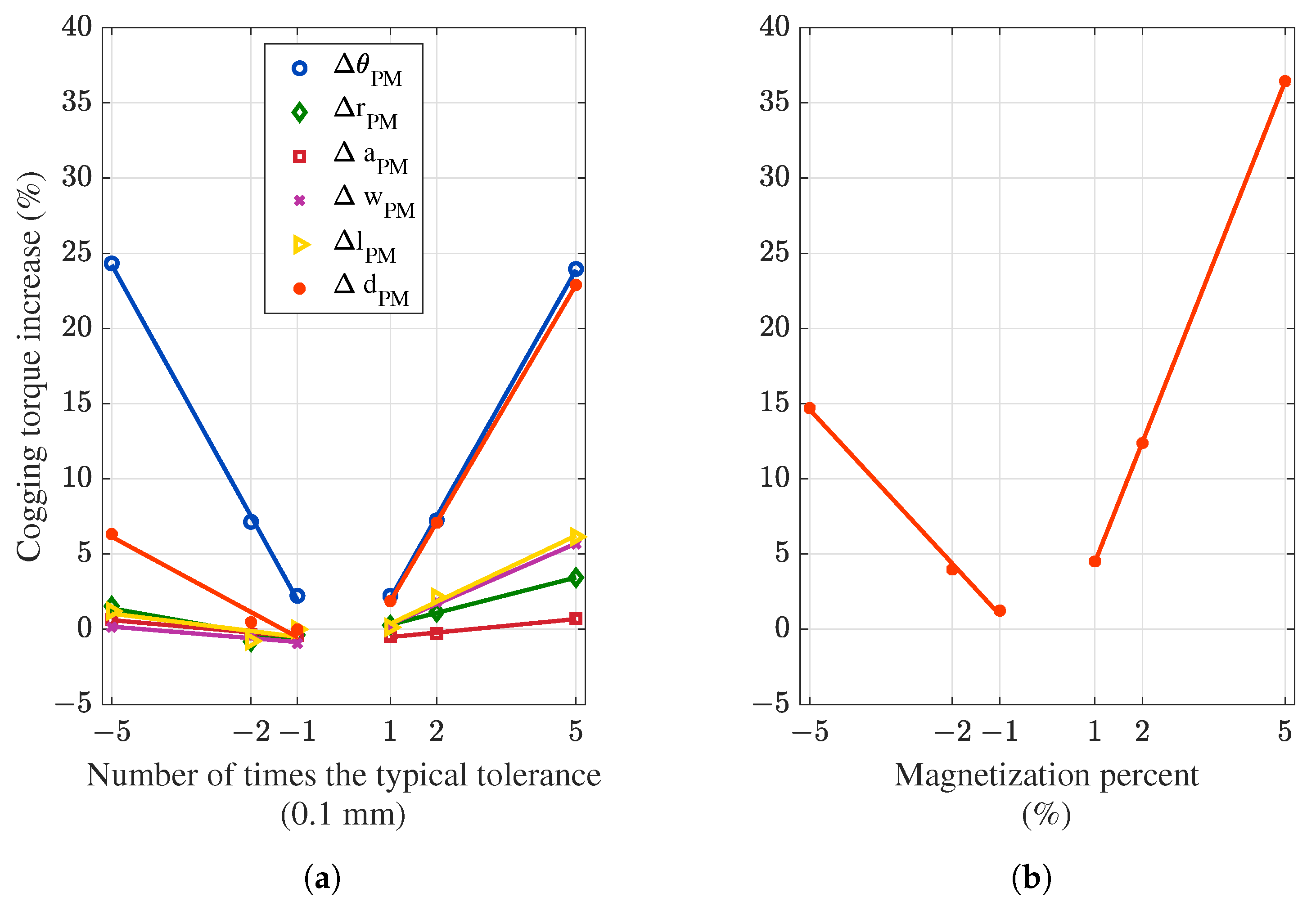
Figure 5 presents the impact of each fault type (applied over the dummy magnet only) on the cogging torque of the AFPM machine. The impact of dimensional faults is shown in
Figure 5a, whilst the remanence deviations are depicted in
Figure 5b.
From
Figure 5a, it can be seen that all addressed faults increase the cogging torque magnitude, but each one to a different extent. The most significant effect on cogging torque is produced by the angular displacement followed by the depth of the magnets. The angular displacement directly affects the permeance of the airgap, whilst the depth variation creates the highest volume variation of the magnets among dimensional tolerances. It may be noted that angular position faults have the same impact regardless of whether positive or negative deviations are considered. This can be explained since the counterclockwise or clockwise displacement of a single magnet results in the same overall geometrical distribution of the magnets. Instead, the positive magnet depth deviations cause more impact than negative deviations, which is also true for the other fault types.
From
Figure 5b, it can be seen that remanence deviations greatly increase the cogging torque of the machine as well. The cogging increase is critical for positive deviations and less relevant for negative deviations.
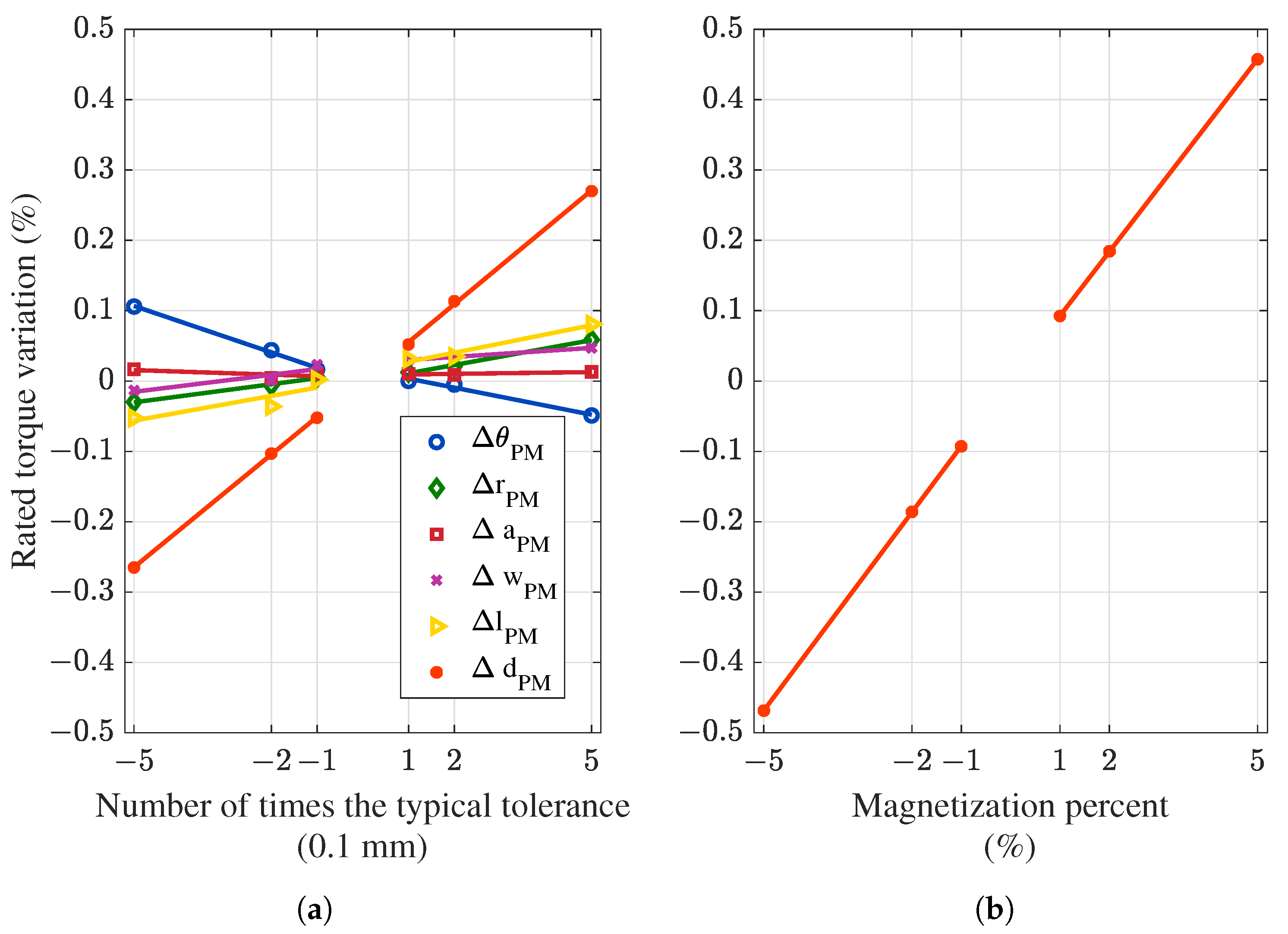
In
Figure 6, the impact of the studied faults (when present on the dummy magnet) on the rated torque of the machine is shown. From
Figure 6a, it can be seen that deviations in the axial length or the angular position of the dummy magnet have the most significant impact on the rated torque of the machine. In the case of the angular displacement of the dummy magnet, it is relevant to determine whether the deviation is counterclockwise or clockwise. Contrary to what happens when analyzing the cogging torque, the direction in which the magnetic field generated by the stator currents rotates, the mechanical sense of rotation, and the relative position of faulty magnets affect the torque generation. Instead, deviations in the axial length of the dummy magnet should have the most significant impact among the dimensional tolerances of the magnet since varying the axial length of the magnet results in the highest variation of the magnet volume. When the dummy magnet is larger, slightly more flux is imprinted on the airgap and thus the electromagnetic torque slightly increases. The opposite effect is observed when decreasing the dummy magnet volume. From
Figure 6b, it may be noted that the remanence deviation can cause a torque variation which is positive when the magnet is more magnetized and negative when the magnet is demagnetized. Nevertheless, the impact of all studied faults on the rated torque (0.2–0.5%) is less significant than on the cogging torque of the machine (5–35%).
The deep-seated reason behind the low impact of tolerances on the electromagnetic torque is the obtained low variation in the airgap flux density. This can be noted from
Figure 7, which presents the harmonic components of the normal airgap flux density for the most severe cases of
Figure 6. Mean torque is strongly related to the main component of the airgap flux density (harmonic order 5 in this case due to the pole count), which is not altered in the presence of dimensional or remanence tolerances.
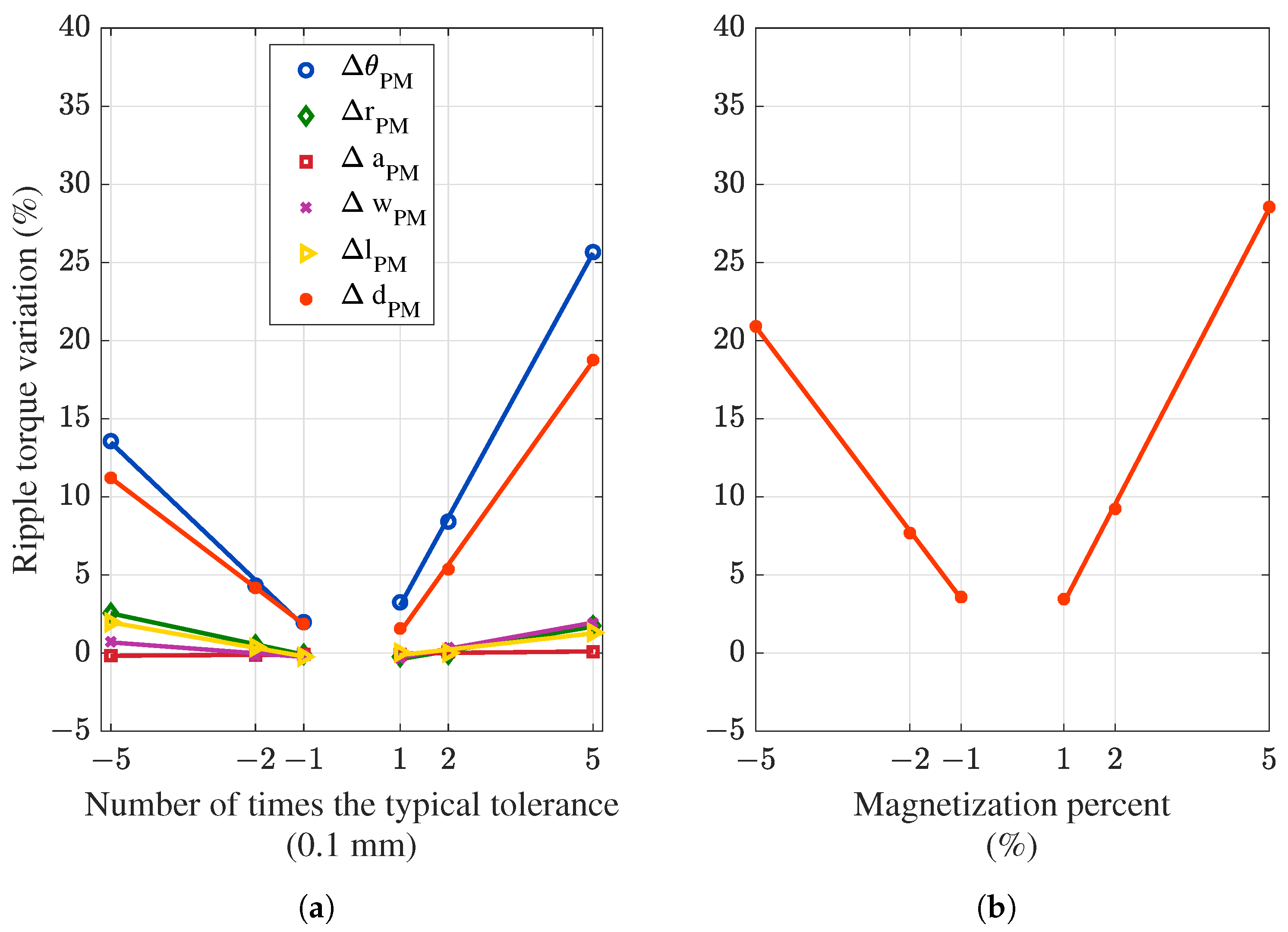
In
Figure 8, the impact of the studied faults (when present on the dummy magnet) on the torque ripple of the machine is shown. From
Figure 8a, it can be seen that all the evaluated deviations increase the ripple torque. The angular displacement of magnets has the most significant effect on the ripple torque, followed by the depth variation of magnets. The magnitude variation of the torque ripple when the magnets are deeper or angularly misplaced is similar to that of cogging torque. However, counterclock or clockwise displacement of a single magnet results into different ripple variation, as opposed to cogging case. In addition, positive magnet depth deviations cause more impact than negative deviations, which translates into larger magnets contributing with more ripple than shorter magnets.
From
Figure 8b, and similar to the cases of cogging torque and rated torque, remanence deviations greatly increase the torque ripple of the machine.
In summary, the angular displacement, magnet depth deviations, and magnet remanance variation may cause the most relevant effects on the machine. However, these preliminary findings only reveal the general response of the performance indices of the machine when a single magnet is faulty. A more detailed evaluation of the faults when present in multiple magnets, as well as when combined, is carried out in the following section to deeply analyze the electromagnetic response of the machine.
4. Statistical Analysis
In this section, a statistical analysis of the response of the machine when bearing different dimensional and assembly faults within typical tolerance ranges is presented. This considers the evaluation and analysis of several combinations of faults when present in the magnets of the machine.
4.1. Methodology: Superposition Method
It is well known that one of the main drawbacks of 3-D FE analysis is the high computational burden. In the case of AFPM machines, this is particularly relevant since simulations in most analyses require to be carried out by means of 3-D models. For instance, the evaluation of a single performance index of the selected machine takes up to 4 h to complete using a desktop computer containing an 8-core 16-thread Ryzen 5800x processor, 128 GB of RAM, and PCIE SSD. Considering the aforementioned time in the case of a tolerance analysis which involves the evaluation of several thousands of simulation runs, this translates into the analysis being impracticable. Therefore, a different approach needs to be considered when assessing the tolerance analysis of an axial topology machine.
In this paper, the issue of a fast evaluation of several combinations of faulty magnets is addressed through the proposal of an adapted semi-analytic superposition method, based on the approach presented in [
25]. Harmonic components of torque (HC) (cogging or rated) can be expressed as the sum of native harmonic components (NHC) and additional harmonic components (AHC). NHC is the harmonic content of the torque signal of the faultless machine, while AHC represents the harmonic content that appears when the machine is faulty.
Taking into account that the torque signal (
T) is a periodical function that depends on the rotor angular position
, then:
is obtained by carrying out a 3-D FE simulation of the faultless machine, whilst
T is obtained by simulating a machine that has a magnet with a specific fault (e.g., remanence variation). Following Equation (2),
is obtained, which represents the additional content that appears when having that specific fault on a magnet. The torque signal of a machine that have several magnets with that fault can be obtained by considering
as many times as faulty magnets the machine has, and evaluating the spatial displacement of each faulty magnet to obtain the final torque waveform. In
Figure 9, the flowchart of the proposed method is depicted, which allows to evaluate the machine performance considering different magnets configurations and manufacturing tolerances with relatively low computational burden.
In order to validate the proposed superposition method (SM), 10 random machine designs (with random faults distributed in the magnets of the machine) were assessed and compared with the results obtained by full FE simulations. To quantify the accuracy of the estimation obtained from the superposition method, the mean absolute error (MAE) is calculated as:
where
is the curve obtained by means of the superposition method,
is the curve given by full FE simulations, and
n is the number of samples (points) evaluated in each curve.
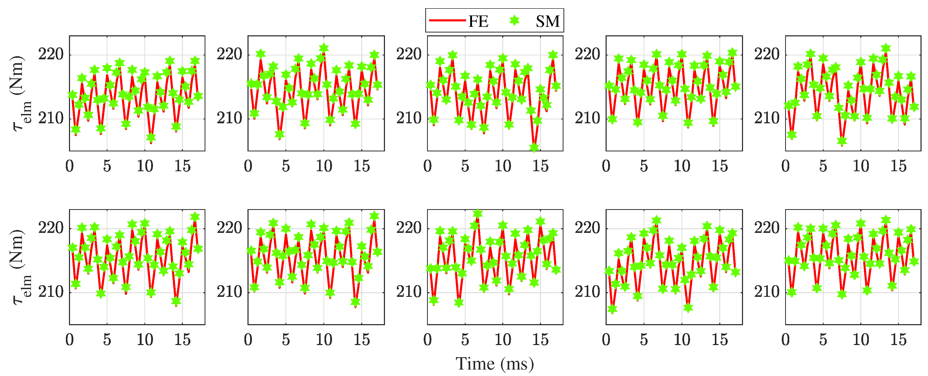
In
Figure 10, the comparison of the obtained cogging torque between FE-only and the proposed superposition method (SM) is presented. From
Figure 10, it can be noted that the proposed SM has a good agreement with the only-FE evaluation, and the former can predict the deviations inserted in the torque signals with good accuracy. The MAE calculated for the cogging torque signals of
Figure 10 is lower than 7% in all cases. Furthermore, the peak-to-peak value of the cogging torque obtained through the semi-analytical method was at most deviated in 3% when compared with the full FE results. Furthermore, it can be noted that there are cases in which the cogging torque is significantly different from the faultless machines (upper left graph of
Figure 10), and the SM is able to predict these variations.
In
Figure 11, the comparison of the calculated electromagnetic torque between FE-only and the SM is presented. From
Figure 11, it may be seen that the proposed SM is concordant with the only-FE evaluation. This is quantified by means of a low MAE: in all 10 random tests, the MAE is lower than 1%. This confirms the feasibility of evaluating the cogging torque and rated torque of faulty machines through the superposition method with acceptable accuracy.
4.2. Probabilistic Approach
By means of the superposition method, multiple faulty machines can be assessed considering a probabilistic approach. In the literature, the occurrence probability of the different manufacturing tolerances that can affect a machine may follow a uniform distribution or a normal distribution. The uniform distribution is usually adopted for carrying out worst-case analyses, whilst the normal distribution is used to better represent the outcome of a real manufacturing process. In this paper, a normal distribution is adopted, and the occurrence of deviations is modelled through two statistical indicators: the mean value (
) and the standard deviation (
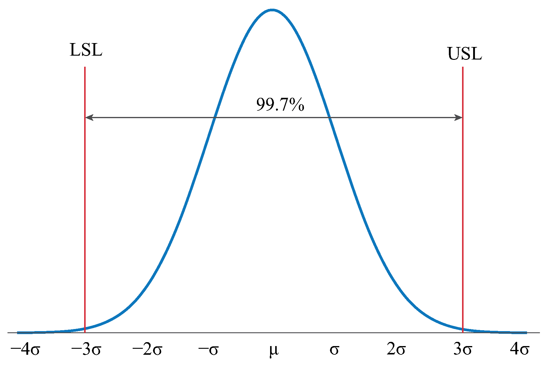
). The mean value is equal to zero, which relates to the parameters of the machine being the nominal values in the absence of deviations or faults. This is the ideal case and the center of the probability distribution since manufacturing procedures intend to obtain this value as the outcome of the process. Instead, the value of the standard deviation is defined considering the maximum tolerance that can be present in the manufacturing process. In the normal distribution, and as depicted in
Figure 12, around
of the data is found within
, and thus sigma can be approximated as:
where LSL and USL are the lower and upper specification limits, respectively, which are derived from the tolerance requirements. In this work, LSL and USL comprise deviations from two times the typical negative deviation to two times the typical positive deviation, i.e, LSL = −0.2 mm and USL = 0.2 mm in the cases of dimensional parameters subject to tolerance. This aims to support a statistical analysis beyond typical tolerances found in a standardized manufacturing process but also considering these typical tolerance ranges. The probability distribution of the seven types of tolerance (e.g., angular displacement, axial length, etc.) are considered independent from each other, and the different types of tolerances have the same chance to be present in the machine. Therefore, from these seven probability distributions, a set of representative machines (with faulty magnets) can be devised, evaluated and compared.
4.3. Results
A total of 10,000 designs with several magnet faults was created following a normal distribution of tolerances, and the cogging torque and the rated torque of these designs is obtained through the superposition method. In addition, the observed difference between the performance indices of the
i-th design (
) belonging to the set and the indices of a faultless design (
) is determined through the following variation factor (VAR):
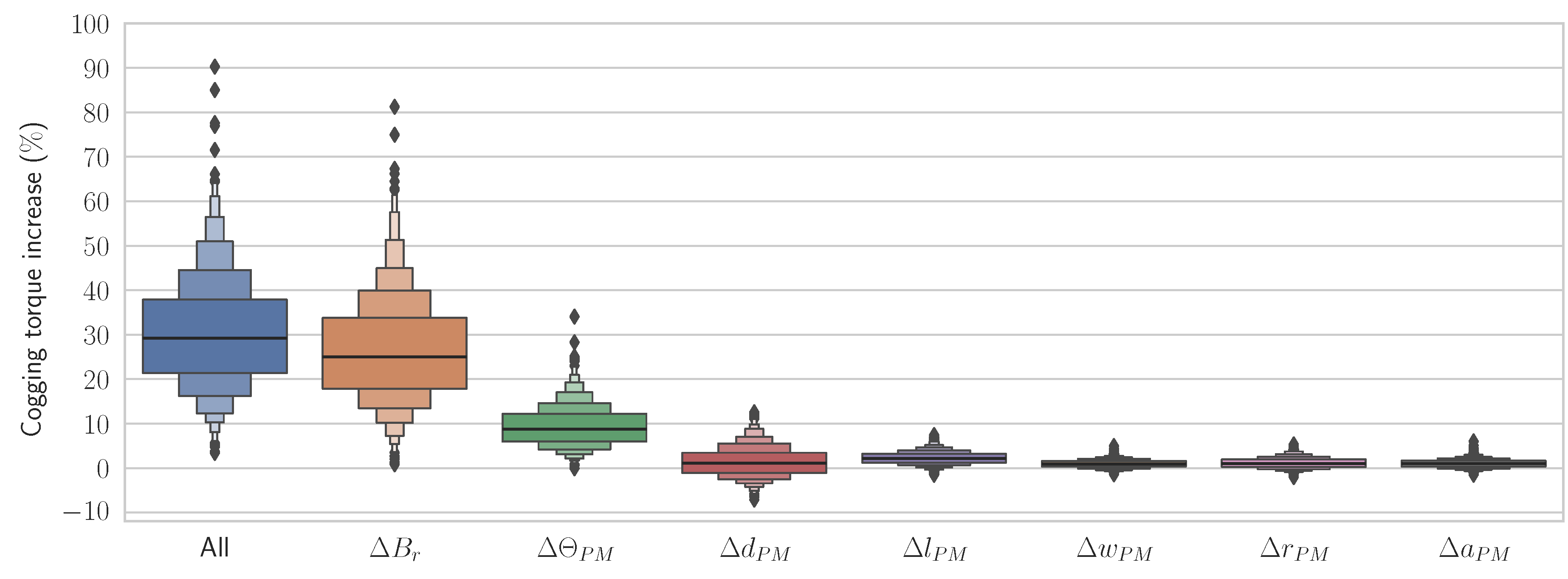
In order to better visualize the outcome of this assessment, relevant statistical indicators are calculated and grouped into a boxplot, which shows the observed variation of the cogging torque and rated torque of the set of assessed designs.
Figure 13 presents the boxplot when evaluating the cogging torque, which groups the data into deciles represented by rectangles of different width, and also shows the median (highlighted as a thicker horizontal line) and extreme values.
From
Figure 13, it is observed that magnet remanence produces the largest increase in cogging torque, which is represented by a median of +25%. This means that in a manufacturing process that deals with remanance tolerances of
, more than 50% of the resulting machines will develop a cogging torque that is 25% higher than that originally conceived by design. The angular displacement of magnets, which is particularly relevant in the case of ironless core structures, increases the cogging torque as well, considering a median of +8%. Instead, axial and radial displacement, as well as length, width and depth variations of the magnets do not produce significant changes in cogging torque: the median of the resulting increase is around zero for all these cases (lower than 1%), and the standard deviation is very low (lower than 3%). Notwithstanding, the axial length can be of interest since it results in the greatest PM volume variation and has the greatest dispersion (3%) of all non-highly significant tolerance types. Moreover, there are certain combinations of deviated magnet depths that leads to a torque cogging decrease, down to −10% in very improbable scenarios.
In the case that all tolerances are evaluated simultaneosly, the median of the cogging torque increase is 29%. It is observed that summing the independent contributions (medians) of remanence and displacement of magnets is not equal to this 29% increase. Furthermore, the increase in cogging torque as a consequence of remanence variations only is very similar to the median when all tolerances are considered simultaneously. From this analysis, it is clear that both remanence and angular displacement of magnets have, effectively, an important impact on the cogging torque of the AFPM machine. These tolerances should not be neglected when conducting a tolerance analysis of these designs. Since magnet manufacturers often provide remanence tolerances within to , it is therefore highly probable that the cogging torque of a built AFPM machine is considerably higher than the originally conceived.
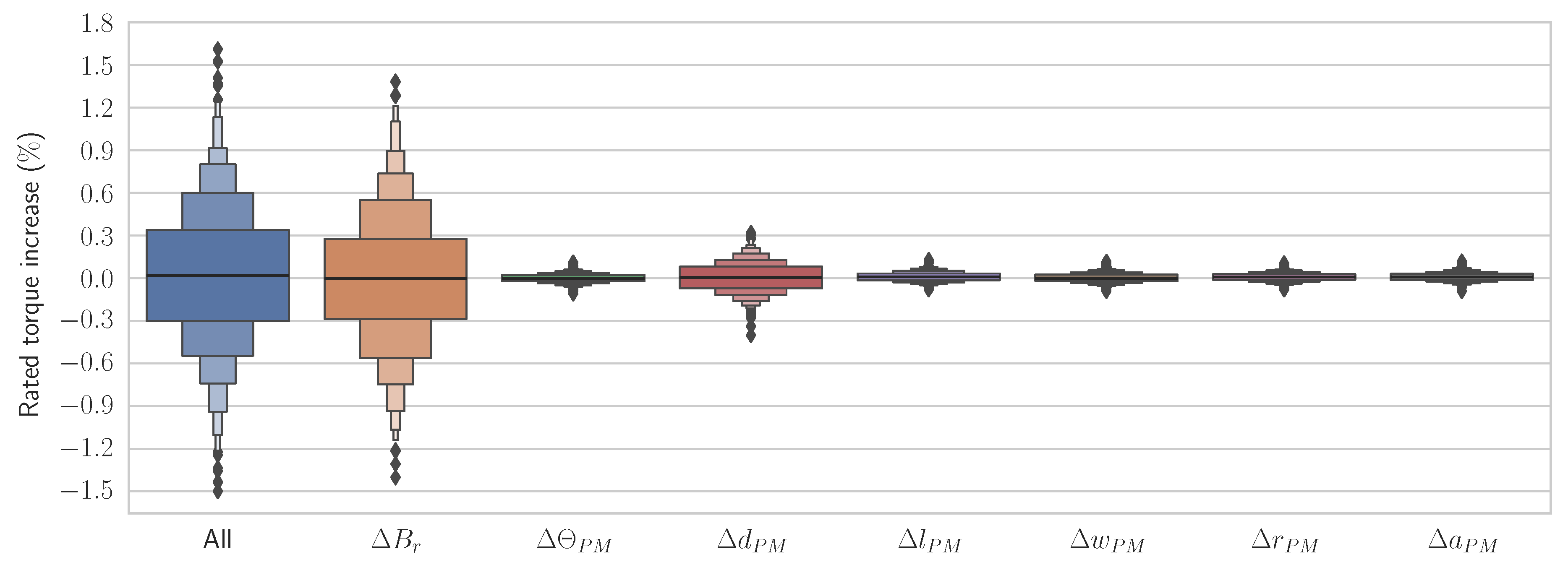
Figure 14 presents the observed rated torque variation with respect to the faultless machine. From
Figure 14 it should be noted that magnet remanence has the highest impact (although insignificant) on the cogging torque, with a dispersion of around 0.6%, followed by magnet depth variations, which develop a dispersion of around 0.1%. This means that there are several machine samples that provide a mean torque that is within
. However, it may be noted that the median of the rated torque variation of all fault types is around 0%, and that in the absolute worst case evaluated (extremely unlikely), the rated torque will be decreased by 1.8%. Thus, it may be concluded that dimensional, positional or remanence tolerances cobmined do not greatly affect the torque capacity of the machine.
Figure 15 shows the estimated peak-to-peak torque ripple variation with respect to the faultless machine. From
Figure 15 it may be observed that magnet remanence has a relevant impact on the torque ripple of the machine, with a median of +25%. In addition, the angular displacement of magnets also provides a significant ripple increase, considering a median of 7%, whilst the magnet depth variations develop a median of 4%. The observed dispersion of the remanence deviation boxplot is very high, as the standard deviation is 25.7%, there are some unlikely combinations that can lower the ripple by around 2%, and there are some other unlikely cases that can provide up to a 63% ripple increase.
From the comparison of
Figure 13 and
Figure 15, a similar behavior can be observed: magnet remanence, angular displacement and depth variations have the most significant impact, with medians higher than 5%. Moreover, when combining all types of faults, the resulting median is similar for both cogging and ripple torque, hovering at 30%. Similarly, axial and radial displacement, as well as length, width and depth variations of the magnets do not provide a significant contribution to cogging or ripple torque variations, and their real impact cannot be easily analyzed by means of the results of the proposed superposition method. Since the error of the superposition method is comparable in magnitude order, severe estimation noise may be included in these low-magnitude boxplot results. Notwithstanding, the low contribution and lack of significance of these parameters can be stated within acceptable accuracy and certainty.
