Abstract
Precision spindle and bearings are the key components in precision machine tools. These structures greatly affect the machining accuracy and service life of the machine tools. In this paper, considering the uncertainty of rolling elements when the bearings are working at high speed, a new 2D equivalent simulation model of angular contact ball bearing was established based on the general finite element software, Abaqus. Meanwhile, the equivalent material parameters of virtual bearing ball in this 2D model were obtained via a standard bearing stiffness test and a parametric inversed method. The time to calculate of this model is reduced by 200 times compared with the 3D bearing simulation model. Then, the 2D equivalent simulation model of the spindle was established based on the 2D bearing model, which is used to calculate the axial stiffness and maximum contact stress between bearing balls and inner/outer rings in different assembly parameters. The results show that the stiffness of the spindle increases slowly at first, but then increases rapidly to a peak value after the bearing inner spacer sleeve is in contact with the bearing inner ring, and finally tends to stable, with the preload of the spindle continuing to increase.
1. Introduction
As the key component of machine tools, high-precision spindle plays an important role in the manufacturing of a machine tool. Structural stiffness, manufacturing accuracy and motion performance of the spindle all determine the quality and cutting efficiency during machining. As the key component of the spindle, bearings greatly affect the service performance of the spindle. Considering the structure, accuracy and performance of all the kinds of bearings, angular contact ball bearing is generally selected as the support bearings of the spindle due to their nice stability, high accuracy, stable operation and ability to bear radial and axial load at the same time. It is a kind of rolling bearings. Usually, angular contact ball bearings are installed on the spindle in pairs and are widely used in precision machine tool spindles. In order to improve the machining accuracy of the precision machine tool and extend its service life, it is necessary to establish accurate and effective models of spindle and angular contact ball bearings, which can be used to analyze their stress state, optimize structure and improve performance.
Since the 1950s, numerous scholars have used analytical calculation methods to conduct theoretical research and modeling on the spindle and bearing system. For example, Palmgren [1] proposed to use the static model of ball bearing to calculate the bearing deflection and load distribution under combined load. After the “raceway control hypothesis” was proposed, Jones [2,3] established a classical bearing dynamics analysis model considering the centrifugal force and gyroscopic moment of the bearing ball based on this theory. However, Wang [4] abandoned the “raceway control hypothesis” and proposed a new quasi-static analysis model. In addition to this method, people also use the dynamic analysis method. Gupta [5,6] developed a complete dynamic model to simulate the transient motion of the ball and cage. It can also simulate the running state of the ball. Xi et al. [7] proposed the dynamic model of contact ball bearing based on the model developed by Gupta, established the finite element model of spindle based on Timoshenko beam theory, simulated and calculated the time-history response of the tool under different cutting forces and ultimately verified it through experiments. Cao et al. [8] used the Gupta dynamics model to calculate the machining error of the machine tool spindle, and optimized the fit clearance of the bearing to meet the design requirements of the spindle. The establishment of the above mathematical models has greatly promoted research on the contact theory of the spindle and bearings of precision machine tools.
After the emergence of computer simulation technology, people applied this technology to analyze the spindle and bearing system, and established an entity model close to the structure and service condition of the spindle and bearing, which greatly improved the efficiency and accuracy of calculation. Liu et al. [9] obtained the temperature field of the spindle system in the thermal equilibrium state using the finite element simulation method, and calculated the maximum thermal deformation of the spindle at different speeds. Yu et al. [10] proved that the finite element solution of dynamic contact characteristic parameter calculation of high-speed precision angular contact ball bearing is in great agreement with the analytical solution of Hertz contact theory, based on finite element simulation. Wang et al. [11] used the finite element method and established a 3D simulation model of the bearing. Then he analyzed the contact characteristics of thrust ball bearing with large contact angle. Comparing the calculation results with the classical Hertz contact theory solution, it can be proved that the bearing capacity of the designed bearing meets the requirements. The above results prove that the computer simulation technology can meet the requirement of researching spindle and bearing system.
As one of the important parameters of bearings, stiffness determines these service performances. In order to increase bearings stiffness, usually a certain preload should be applied to them before serving. So in production, the bearing stiffness is generally improved by increasing the preload. The spindle preload can be divided into positioning preload and constant pressure preload. Zhang et al. [12] compared the bearing stiffness under different preload modes via the analytical method, and the results supported that the larger the preload, the better the bearings stiffness, no matter whether there is a positioning preload or a constant pressure preload. In addition, under positioning preload, the bearings stiffness changes less with the rotation speed, which is more suitable for rough machining. Through the comparison of temperature rise, dynamic stiffness and service life of bearing under high speed and light load, Jiang et al. [13] concluded that the hydraulic preload with variable pressure could effectively improve the bearing performance compared with the traditional constant pressure preload. The spindle studied in this paper is in positioning preload, and it can be applied through the height difference between inner and outer spacer sleeves.
At the same time, the increase of the preload will make the contact load between the bearing rolling element and the ring raceway larger, which will aggravate the wear of the bearings. It is important to balance the bearing stiffness and the contact load, which aims to minimize the bearings wear with great stiffness. Li et al. [14] established a model of spindle to conduct modal simulation of the preloaded bearing system. Taking 7005C bearing [15] as an object, he studied the contact characteristics between rolling elements and raceway. Then he used the model to obtain bearings stiffness for finite element simulation analysis, and verified the accuracy of the simulation results through the modal test. Liu et al. [16] explored the raceway contact performance of bearings under dynamic load, and used the “slice model” to illustrate the necessity of considering the non-uniformity of the load for the study of contact performance of rolling bearings. It can be seen that the non-uniformity of the load will also affect the contact performance of the rolling bearing. Li et al. [17] found that non-uniform preload can improve the stability of the spindle by comparing the rotation centers of the spindle under different preloads.
The above research results show that preload has great impact on spindle stiffness. Naturally, some scholars raised the question whether the spindle stiffness can be predicted with the preload value. E. Ozturk et al. [18] established a stability model of cutting edge, FRF and cutting force coefficient combined with speed to predict spindle stiffness under different preload. Establishing effective and accurate calculation models is an important means for the research of spindle and bearings. Not only the mathematical models, but the computer simulation models should be established. Due to the improvement of machine tools’ accuracy and the expansion of production scale in recent years, the calculation accuracy and efficiency of simulation models have been given higher requirements. In the research of angular contact ball bearings at home and abroad, many mathematicians establish local reduced 3D models for calculation according to the symmetry of bearings, in order to obtain accurate and reliable calculation results. However, due to the complexity of the 3D model, the number of meshes and nodes is large but computational efficiency is low, so they cannot meet large-scale simulation calculation requirements. In order to improve the calculation efficiency, in this paper, a new equivalent 2D axisymmetric model of 7008 angular contact ball bearing [19] was established by using the general finite element software, Abaqus. At the same time, a standard bearing stiffness test was carried out to verify its practicability. Applying the bearing equivalent 2D model to the spindle, the spindle equivalent 2D model is established. The spindle stiffness in different assembly and structure parameters was calculated to ensure that the spindle can resist deformation. Meanwhile, the contact stress between bearing rolling element and raceway during the preloading process can also be calculated to provide a reference for the subsequent prediction of service life.
2. Bearing and Spindle
2.1. Angular Contact Ball Bearing—7008C
The bearing studied in this paper is angular contact ball bearing—7008C, which is widely used in the spindle serving at high speed and precision. As shown in Figure 1a, it is mainly composed of an inner ring, an outer ring, a rolling element (18 pieces), a cage and lubricating grease. And then, the important parameters of the bearing can be tagged in the simplified principal section without the cage, as shown in Figure 1b.
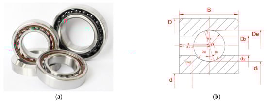
Figure 1.
(a) Angular contact ball bearing 7008C and (b) important parameters in the simplified principal section.
The main structural dimensions are shown in Table 1. It needs to be noted that the simulation models used in this paper are static analysis models; the influence of grease and the cage is ignored. The material of the bearing rings is GCr15, and the material of the rolling elements is Si3N4. The material parameters are shown in Table 2.

Table 1.
Structure parameters of angular contact ball bearing.
Table 2.
Material parameters of bearing ring and rolling element.
Using the bearing above, the standard bearing stiffness test was carried out to obtain the stickout of this bearing (7008) under different preloads. In this test, the data of eight test samples was totally collected. The stickout measuring instrument is shown in Figure 2, and the measuring result is shown in Table 3. According to the test’s result, the increase trend of the stickout with preload can be obtained.
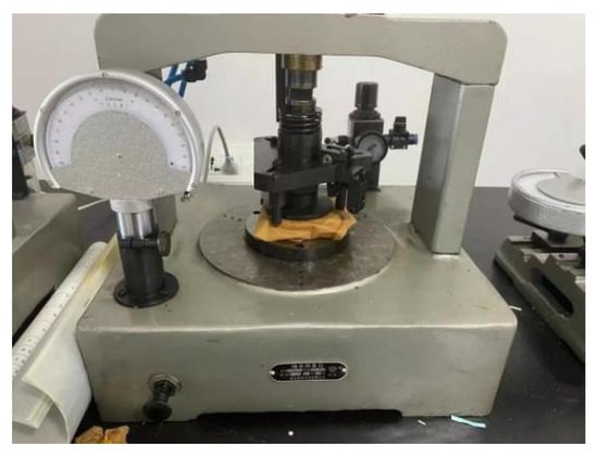
Figure 2.
Stickout measuring instrument of angular contact ball bearing.
Table 3.
Stickout measuring result of the test bearing samples under different preloads.
2.2. Mechanical Spindle—BT30
The spindle studied in this paper is a mechanical spindle used in a precision drilling and tapping machine tool, as shown in Figure 3. It is mainly composed of a mandrel, an external sleeve, an inner spacer sleeve, an outer spacer sleeve, an angular contact ball bearings, a front end cover, a labyrinth ring, a rear end cover, a lock nut, etc. The angular contact ball bearing is the key component, and a single spindle is equipped with four bearings, which are assembled in pairs front and rear in DT mode. The main structure and their dimensions are shown in Table 4.
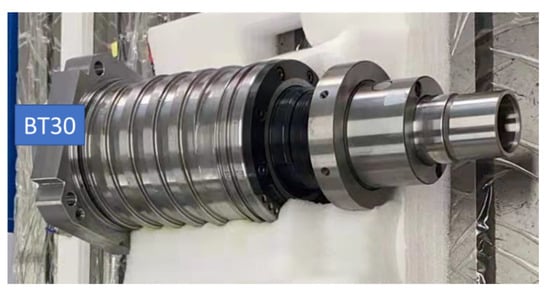
Figure 3.
Mechanical spindle—BT30.
Table 4.
Parameters of mechanical spindle BT30′s components.
3. Methodology
3.1. Equivalent 2D Model of Bearing
Considering the uncertainty of bearing balls when the bearing is working at high speed, the limited number of rolling elements of the bearing can be simplified as a virtual rotating element which is shaped like a hoop, as shown in Figure 4a. After equivalence, the structure of all the bearing components is rotary bodies. Theoretically, when the bearings only sustain axial load, each cross section of one bearing has the same stress state. An equivalent 2D bearing model can be established to substitute for the 3D model, which can reflect the stress state of bearing cross section, as shown in Figure 4b.
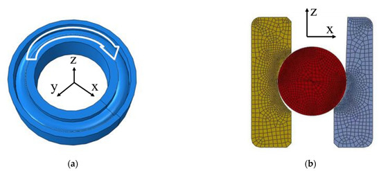
Figure 4.
The equivalent 2D model of bearing. (a) The equivalent 3D bearing model in high speed. (b) The meshes of 2D bearing model.
Table 5 shows the mesh parameters of two models. It can be seen that the number of nodes and elements of the equivalent 2D model decreases significantly, compared with the full-scale 3D model. As a result, the calculation speed of 2D model is substantially improved compared with the 3D model.
Table 5.
Comparison of mesh parameters between 3D and 2D model of bearing.
3.2. Parametric Inversed Method
The virtual rolling element in the equivalent 2D bearing model is a hoop-like rotating structure rather than a series of balls; therefore, the experimental mechanical property parameters of ceramic balls can no longer be used in this model. The corresponding equivalent material property parameters of virtual bearing ball in the 2D bearing model can be obtained by using a parametric revered method.
Firstly, assuming that the virtual bearing ball is an isotropic elastomer, its elastic modulus and Poisson’s ratio are constants. Then, a series 2D bearings model is established using different equivalent material property parameters of virtual rolling element and . The simulated stickout and preload curve of bearing with different material parameters of and can be obtained based on the 2D bearing model, as follows:
It is assumed that the experimental stickout with different preload is:
By comparing the simulated and experimental data, the maximum simulated deviation of each simulated stickout can be expressed as follows:
A simple inversed method has been proposed in this paper; the corresponding and are the inversed equivalent elastic modulus and Poisson’s ratio, when is at its minimum.
3.3. Hertz Point/Line Contact Theory
The contact stress between bearing inner/outer rings and balls obtained via the 2D bearing model is different from the actual contact stress of the 3D bearing model, due to the simplification of the 2D bearing model. Therefore, an indirect method was introduced to calculate the actual contact stress of the 3D bearing model by using the contact stress results of the 2D bearing model, based on the classical Hertz point and line contact theory [20,21].
According to the classical Hertz point contact theory, the contact region’s projection of two elastomers is approximately elliptic. For the elliptic contact region, the stress at its geometric center can be calculated as follows:
where is the contact pressure on two objects; and represent the major and minor axes of the projected ellipse in the contact region. The values of and can be calculated via the curvature function of the components. This theory is applicable to the calculation of the maximum contact stress in the 3D bearing model.
In Figure 5, the bearing ball is denoted as 1, the bearing inner ring as 2 and the main plane is denoted by x and y, respectively. In this way, the radius of curvature of the bearing ball in plane x can be denoted as , and the curvature is the reciprocal of the curvature radius. In addition, the curvature is specified to be positive for convex surfaces and negative for concave surfaces. The equations are as follows:
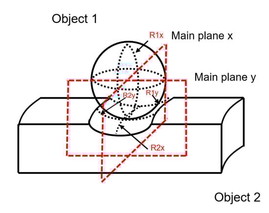
Figure 5.
Schematic diagram of contact geometry.
In order to accurately describe the contact state between the two corresponding rotary surfaces, the equations of the sum of curvatures and the differences of curvatures are defined as:
can also be calculated by another equation as follows [22]:
where is the elliptic eccentricity parameter; and are the complete elliptic integrals of the first and second kinds, respectively. The relevant equations are as follows:
Brewe and Hamrock proposed a set of simplified approximate equations for , and by means of the least square method of linear regression [22]. Firstly, the equivalent radius in each direction can be defined as follows:
Then the simplified approximate equations of , and are as follows:
Based on elastic theory, the contact ellipse parameters , and the elliptial-contact deformation at the center of contact can be calculated as follows:
where can be calculated with Equation (10), and , and can be calculated with the following equations:
For the elliptic contact region of the bearing 3D model, the maximum contact stress appears in the geometric center, and the equation is as follows, based on Equation (5):
where is the total normal contact pressure in the 3D model; is the number of rolling elements. According to Equation (27), the value of two contact ellipse parameters and should be obtained to calculate the maximum contact stress. Firstly, define as the equivalent elastic constant, which can be calculated as follows:
The parameters and of the contact ellipse can be expressed by the following equations:
Based on the above equations, it can be deduced that the equation to calculate the maximum contact stress between the ring and the ball is:
For the equivalent 2D model, the “hoop” and the bearing rings are in line contact. Similar to the calculation method of point contacts, the maximum contact stress between the ring and the virtual ball can be calculated with the following equations according to the Hertz line contact theory:
where is the total normal contact pressure on the “hoop”, and assuming that the normal contact pressure is evenly distributed; and are the normal radius of the two elastomers; is the equivalent normal radius; is the length of the contact line.
According to Equations (28) and (33), the maximum contact stress between the ring and the virtual ball in the 2D model is calculated by the following equation:
Considering the total normal contact pressure in the 2D model is equal to the in the 3D model, the relationship between the maximum contact stress of the 2D equivalent model and the 3D model can be expressed by the following equation:
3.4. Equivalent 2D Model of Spindle
Considering the symmetry of the spindle structure, an equivalent 2D model of spindle has been established in this paper based on the equivalent 2D model of bearing, which is shown in Figure 6. The four bearings are divided into two groups, bearing 1, 2 for the first group, bearing 3, 4 for the second group, the first group is installed at the front end of the spindle in pairs, and the second group is installed at the back end of the spindle in pairs. The back end is the preloaded end.
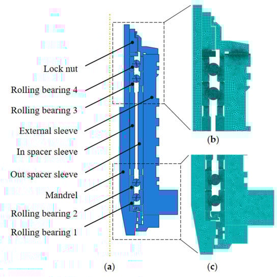
Figure 6.
(a) The equivalent 2D model of a spindle. (b) The meshes of the top half of the spindle. (c) The meshes of the bottom half of the spindle.
At the same time, it needs to be noted that the unnecessary assemblies and structures, such as couplings, cutting rings and springs of the spindle can be omitted to simplify the model because each component has little influence on the macroscopic stiffness and microscopic stress calculation of the spindle. Table 6 shows the mesh parameters of the important components. The same as the 2D bearing model is that the meshes of the components in the 2D spindle model also used quad-dominated meshes. This technique is free and the algorithm is the default algorithm, advancing front.
Table 6.
Mesh parameters of important components in spindle.
4. Results and Discussion
4.1. Parameter Reversion of 2D Virtual Bearing Ball
The virtual rolling element in the equivalent 2D bearing model is a hoop-like rotating structure rather than a series of balls, and the corresponding equivalent material property parameters of virtual bearing ball in a 2D bearing model can be obtained by using a revered method as shown in Section 3.2. Figure 7 shows the maximum simulated deviation by using different virtual elastic modulus and poisson’s ration in 2D model.
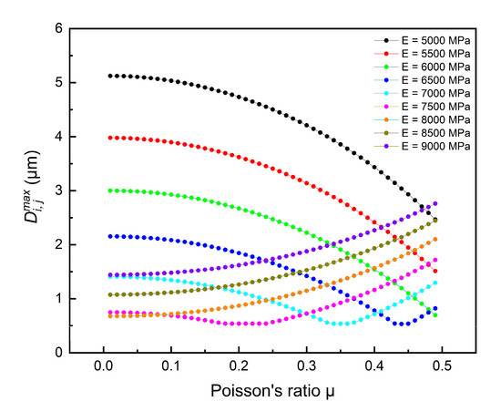
Figure 7.
The maximum simulated deviation by using different and .
It can be seen in Figure 7 that within a certain range of , decreases firstly, and then increases with in the 2D model, in the case of in the 2D model being constant. Similarly, decreases firstly and then increases with the increase of in the 2D model, in the case of in the 2D model being constant.
The smaller the value of , the better the fitting effect will be, when the and corresponding to the are applied to the 2D model. In order to obtain the optimal and more clearly, summarize the minimum value of corresponding to different , as shown in Figure 8. It can be seen that the minimum value of decreases firstly and then increases with the increase in . When is in the range of 6000–8000 MPa, the relationship curve of and has a “flat bottom”, and the maximum value is less than 1 μm.
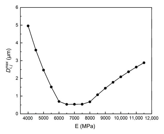
Figure 8.
The relationship between the minimum value of and the equivalent elastic modulus of rolling elements in different .
When the of the equivalent rolling element is 6500 MPa and is 0.44, the value of is the smallest, which is 0.53 μm. This is the optimum elastic modulus and Poisson’s ratio. Considering that the measuring accuracy of the bearing’s stickout measuring instrument at this stage is 1 μm, this calculation error is acceptable in the research object of this paper. Therefore, the above equivalent material property parameters of the bearing’s 2D rolling elements obtained via reverse fitting, including elastic modulus and Poisson’s ratio, can be used as the material property parameters of the rolling elements in the equivalent 2D model of bearing.
Based on the obtained optimal material property parameters of the equivalent rolling element of the bearing, the relationship curve of F and l calculated by using the 2D simulation model of the bearing is compared with the experimental curve (fitting the experimental result shown in Table 3), which is shown in Figure 9.
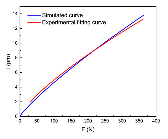
Figure 9.
Comparison of F-l curve of bearing’s 2D model and fitting curve of stickout measuring experiment results.
It can be concluded that the relationship curve between force (F) and displacement (l) calculated for the bearing equivalent 2D simulation model is well fitted with the experimental results. Therefore, the stiffness of the actual bearing can be well simulated by using the 2D axisymmetric model with the rolling elements which have equivalent material parameters.
4.2. Contact Stress Calculation of 2D Bearing Model
According to Section 3.3, the actual maximum contact stress of the 3D bearing can be calculated through the maximum contact stress of the 2D equivalent axisymmetric model by using Equation (35). By substituting the structural and material parameters of bearing into Equation (35), the power function relationships related to maximum contact stress of the bearing ring and balls in the 3D model and the 2D model can be obtained:
For the inner ring:
For the outer ring:
The above equations can be used to calculate the actual maximum contact stress of the 3D bearing ring, based on the bearing rings’ maximum contact stress of the 2D axisymmetric model. In this way, the practicability of the 2D axisymmetric model can be improved substantially.
4.3. Effect of Preload on Mechanical Properties of Spindle
Preload has a significant effect on the mechanical performance of the spindle. Based on the 2D model of the spindle, it can be calculated that the axial stiffness of the spindle increases with the increase of preload, as shown in Figure 10, which is consistent with the previous calculation results [12]. During the above process, other structural parameters of the spindle remain unchanged: the interval difference of the spacer sleeve is set to 30 μm, and the amount of end cover pressing is 10 μm.
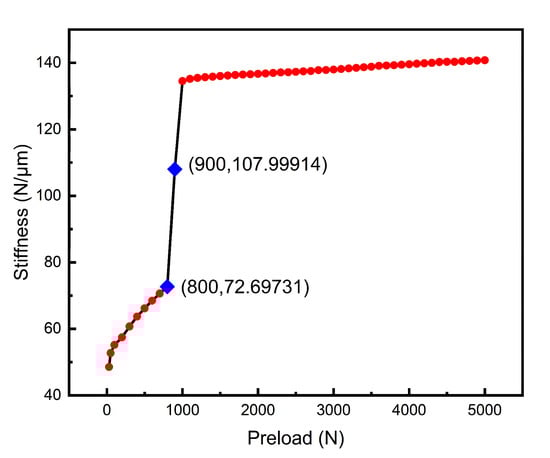
Figure 10.
The relation curve between axial stiffness and preload of spindle.
According to Figure 10, the axial stiffness increases sharply when the preload is 800–900 N, but then hardly changes with the preload and stabilizes at the peak value of 135 N/μm even though the preload reaches 4000–5000 N. In order to explore the reason for the steep rise in stiffness, the maximum contact stress on the top and bottom surfaces of the inner spacer is extracted when the preload is in the range of 30–2000 N, and the result is shown in Figure 11. Within the range of 30–800 N, there is no contact stress on the surface of the inner spacer, but the value of the contact stress is not zero within the range of 900–2000 N.
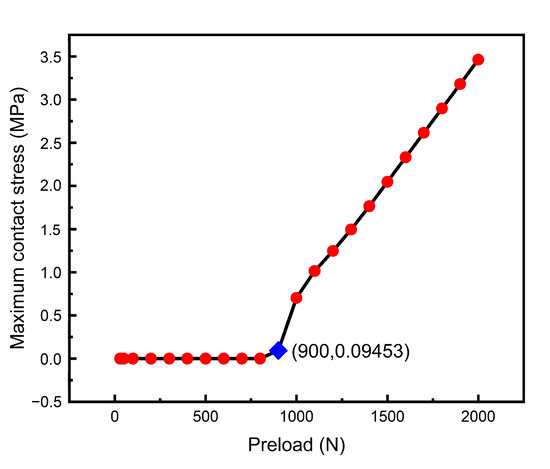
Figure 11.
The relationship curve between preload and the maximum contact stress of top and bottom end faces of inner spacer.
It can be concluded that when the preload is less than 800 N, the inner ring of the rolling bearing 3 is not in contact with the inner spacer sleeve of the spindle, and the stiffness is small at this time. When the preload reaches a certain value between 800 N and 900 N, the contact stress between the inner ring of bearing 3 and the inner spacer sleeve of the spindle occurs. At the same time, the inner spacer sleeve begins to participate in the resistance to deformation, which leads to the sharp increase in the stiffness of the spindle in the range of 800–900 N preload. After that, with the increase of preload, the stiffness increases little, but basically is steady at a certain value.
Therefore, when the spindle is assembled, the preload should be larger than 900N to ensure that the inner spacer sleeve of the spindle is fully in contact with the inner ring of rolling bearing 3, which can improve the stiffness of the spindle. However, excessive preload is not needed; it has no significant influence on the lifting stiffness.
In addition to stiffness, the effect of preload on the maximum contact stress is also important for predicting the service life of the spindle. In accordance with Equations (36) and (37), based on the simulation results of the 2D model, the maximum contact stress of four bearings mounted on the spindle is calculated, as shown in Figure 12.
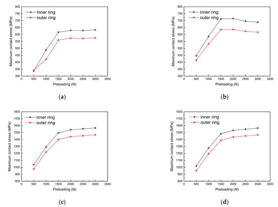
Figure 12.
The relationship curve between maximum contact stress of inner/outer ring and preload of spindle. (a) Rolling bearing 1. (b) Rolling bearing 2. (c) Rolling bearing 3. (d) Rolling bearing 4.
It can be concluded that the maximum contact stress of inner and outer rings of the bearings increases monotonically with the increase of preload. The maximum contact stress of the bearing inner ring is always greater than that of the outer ring. In addition, the maximum contact stress of the second group of bearings installed at the back end of the spindle is larger than that of the first group of bearings.
According to the calculation results, the contact stress of the bearing ring is not only related to the preload force, but also to the installation position of the spindle during serving. On the premise of ensuring high stiffness, the preload of the spindle should not be too large to avoid excessive contact stress, which will affect the bearing service life. When the preload is determined to a certain value, the back-end bearings of the spindle tend to be under greater contact pressure, especially the inner rings of the bearing, so more attention needs to be paid to them during serving.
5. Conclusions
The axial stiffness related to the mechanical properties and the maximum contact stress of the bearings related to the service life of spindle were investigated via a simplified mathematical model in this paper. The following conclusions can be drawn from this study:
- (1)
- The new 2D axisymmetric simulation models of bearing and spindle were established by introducing a virtual rotating structure. The corresponding equivalent material parameters of virtual rotating structure were obtained via a parametric inversed method and the stickout measured result of bearing.
- (2)
- The relationship of the actual maximum contact stress between the roller and the inner/outer ring between the 2D and the 3D bearing model was deduced via the Hertz point and line contact theory of bearing; it can be used to calculate the contact stress of the bearing under different spindle structure and assembly.
- (3)
- The 2D simulation model established in this paper can be used to calculate the stiffness of the spindle and the contact stress of the bearing in the spindle under different bearing structure, spindle structure and spindle assembly parameters.
- (4)
- As the preload of the spindle increases, the axial stiffness of the spindle increases slowly at first, then increases rapidly in the case of the bearing ring being in contact with the spindle spacer sleeve and finally increases very slowly when the contact between the bearing ring and the spindle spacer sleeve is stable.
- (5)
- The maximum contact stress of the bearings’ inner and outer ring is positively correlated with the preload of the spindle. The preload shall be reduced as much as possible under the premise of ensuring that the spindle has a great rigidity to extend its service life.
Author Contributions
Writing—original draft preparation, S.X. and J.L.; writing—review and editing, Y.X. and X.C.; conceptualization and methodology, X.C.; project administration and funding acquisition, P.W. All authors have read and agreed to the published version of the manuscript.
Funding
This work was supported by the Strategic Priority Research Program of the Chinese Academy of Sciences Grant, grant number XDC04000000, and Youth Innovation Promotion Association CAS, grant number 2022186.
Data Availability Statement
Not applicable.
Conflicts of Interest
The authors declare that they have no known competing financial interests or personal relationships that could have appeared to influence the work reported in this paper.
References
- Palmgren, A. Ball and Roller Bearing Engineering, 3rd ed.; Burbank Press: Philadelphia, PA, USA, 1959; pp. 1–12. [Google Scholar]
- Jones, A.B. Ball motion and sliding friction in ball bearings. J. Basic Eng. 1959, 81, 1–12. [Google Scholar] [CrossRef]
- Jones, A.B. A general theory for elastically constrained ball and radial roller bearings under arbitrary load and speed conditions. J. Basic Eng. 1960, 82, 309–320. [Google Scholar] [CrossRef]
- Wang, W.Z.; Hu, L.; Zhang, S.G.; Zhao, Z.Q.; Ai, S.Y. Modeling angular contact ball bearing without raceway control hypothesis. Mech. Mach. Theory 2014, 82, 154–172. [Google Scholar] [CrossRef]
- Gupta, P.K. Dynamics of rolling-element bearings—Part III: Ball bearing analysis. J. Lubr. Technol. 1979, 101, 312–318. [Google Scholar] [CrossRef]
- Gupta, P.K. Dynamics of rolling-element bearings—Part IV: Ball bearing results. J. Lubr. Technol. 1979, 101, 319–326. [Google Scholar] [CrossRef]
- Xi, S.T.; Cao, H.R.; Chen, X.F. Dynamic modeling of spindle bearing system and vibration response investigation. Mech. Syst. Signal Pr. 2019, 114, 486–511. [Google Scholar] [CrossRef]
- Cao, H.; Li, B.; Li, Y.; Kang, T.; Chen, X.F. Model-based error motion prediction and fit clearance optimization for machine tool spindles. Mech. Syst. Signal Pr. 2019, 133, 106252. [Google Scholar] [CrossRef]
- Liu, J.L.; Ma, C.; Wang, S.L. Thermal-structure interaction characteristics of a high-speed spindle bearing system. Int. J. Mach. Tool. Manu. 2019, 137, 42–57. [Google Scholar] [CrossRef]
- Yu, X.K.; Zhao, C.J.; Ge, S.D.; Huang, Q.X. Finite element analysis of axial loaded high speed angular contact ball bearings. Mech. Eng. Auto. 2011, 5, 51–55. [Google Scholar]
- Wang, H.; Dai, S. Study on contact finite element simulation of the high-angular contact thrust ball bearing. Comput. Simul. 2013, 30, 305–309. [Google Scholar]
- Zhang, J.H.; Fang, B.; Zhu, Y.S.; Hong, J. A comparative study and stiffness analysis of angular contact ball bearings under different preload mechanisms. Mech. Mach. Theory 2017, 115, 1–17. [Google Scholar] [CrossRef]
- Jiang, S.Y.; Mao, H.B. Investigation of variable optimum preload for a machine tool spindle. Int. J. Mach. Tool. Manu. 2010, 50, 19–28. [Google Scholar] [CrossRef]
- Li, B.; Zhang, J.B.; Jiang, L.S. A research of shaft modal simulation method based on the preloaded angular contact ball bearing. Appl. Mech. Mater. 2013, 389, 364–370. [Google Scholar] [CrossRef]
- Bian, Q.; Zeng, G.; Zhao, C.J.; Liu, B.Y.; Xiao, Z.G. Kinematics analysis of high-speed angular contact ball bearings based on finite element. J. Mech. Str. 2021, 43, 966–971. [Google Scholar]
- Liu, Y.Q.; Chen, Z.G.; Wang, K.Y.; Zhai, W.M. Non-uniform roller-race contact performance of bearings along width in the rotor-bearing system under dynamic loads. J. Sound Vib. 2022, 538, 117251. [Google Scholar] [CrossRef]
- Li, X.H.; Li, H.F.; Zhang, Y.F.; Hong, J. Investigation of non-uniform preload on the static and rotational performances for spindle bearing system. Int. J. Mach. Tool. Manu. 2016, 106, 11–21. [Google Scholar]
- Ozturk, E.; Kumar, U.; Schmitz, T. Investigation of spindle bearing preload on dynamics and stability limit in milling. CIRP Ann. Manuf. Techn. 2012, 61, 343–346. [Google Scholar] [CrossRef]
- Christian, B.; Stephan, N.; Marcus, G.; Leonardo, C.; Feliciano, G.; Guillermo, M.E.; Lang, D.F. New bearing steel for high-speed applications. MM Sci. J. 2021, 12, 5334–5339. [Google Scholar]
- Hertz, H. On the contact of elastic solids. J. Reine Angew. Math. 1881, 92, 156–171. [Google Scholar]
- Luo, J.W. Analysis and development of rolling bearing. Bearing 2001, 9, 28–31. [Google Scholar]
- Brewe, D.; Hamrock, B. Simplified solution for elliptical-contact deformation between two elastic solids. ASME Tran. J. Lub. Tech. 1977, 101, 231–239. [Google Scholar] [CrossRef]
Disclaimer/Publisher’s Note: The statements, opinions and data contained in all publications are solely those of the individual author(s) and contributor(s) and not of MDPI and/or the editor(s). MDPI and/or the editor(s) disclaim responsibility for any injury to people or property resulting from any ideas, methods, instructions or products referred to in the content. |
© 2023 by the authors. Licensee MDPI, Basel, Switzerland. This article is an open access article distributed under the terms and conditions of the Creative Commons Attribution (CC BY) license (https://creativecommons.org/licenses/by/4.0/).