

Grasping of Solid Industrial Objects Using 3D Registration


Abstract
1. Introduction
- The generation of a model of the object based on a set of point clouds acquired from different points of view. The point clouds are merged by means of a 3D registration procedure based on the ICP algorithm. Once the model is obtained, the grasping pose is selected. It is worth noticing that such a procedure is needed only once.
- The alignment of the obtained model with the current view of the object in order to detect the grasping pose.
- As a difference with respect to expensive 3D scanning systems usually adopted for large production batches, the proposed strategy only requires an off-the-shelf low-cost depth sensor to generate the model and to acquire the current view of the object. Moreover, the proposed system is highly flexible with respect to the position of the object, and it allows one to acquire different views of the object, since the camera is mounted on the wrist of a robot manipulator.
- According to the Industry 4.0 road map, our system is robust to possible failures. In fact, it can detect a potential misalignment between the acquired point cloud and the model. In such a case, the point of view is modified and the whole procedure is restarted.
- While deep-learning-based approaches to object grasping pose detection usually require a huge quantity of data and a high computational burden to train the network, the proposed approach exploits a fast model reconstruction procedure.
2. Related Work
2.1. Object Grasping
- Analytic methods require a knowledge (at least partial) of the object features (e.g., shape, mass, material) and a model of the contact [5].
- Data-driven approaches aim at detecting the grasp pose candidates for the object via empirical investigations [6].
2.2. Three-Dimensional Registration
3. Proposed Approach
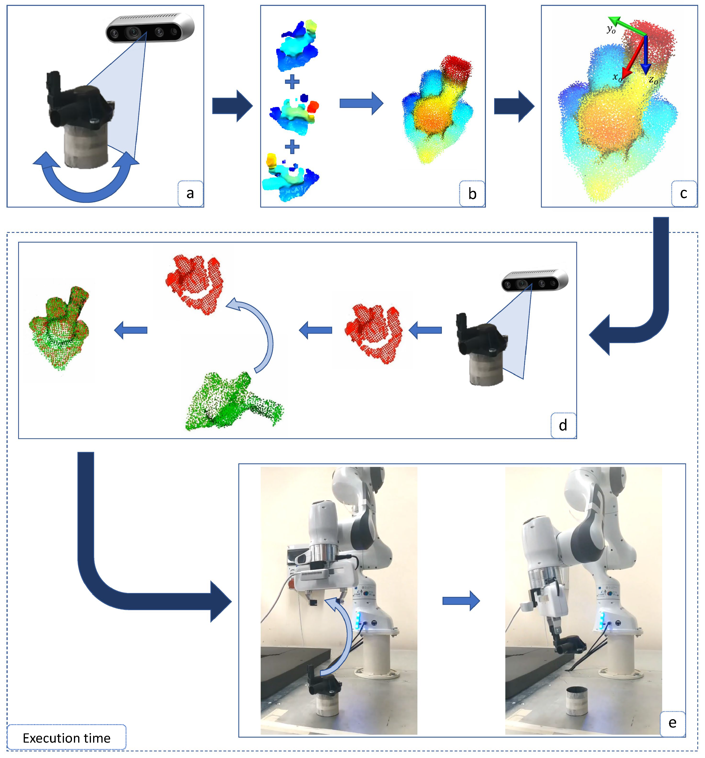
- (a)
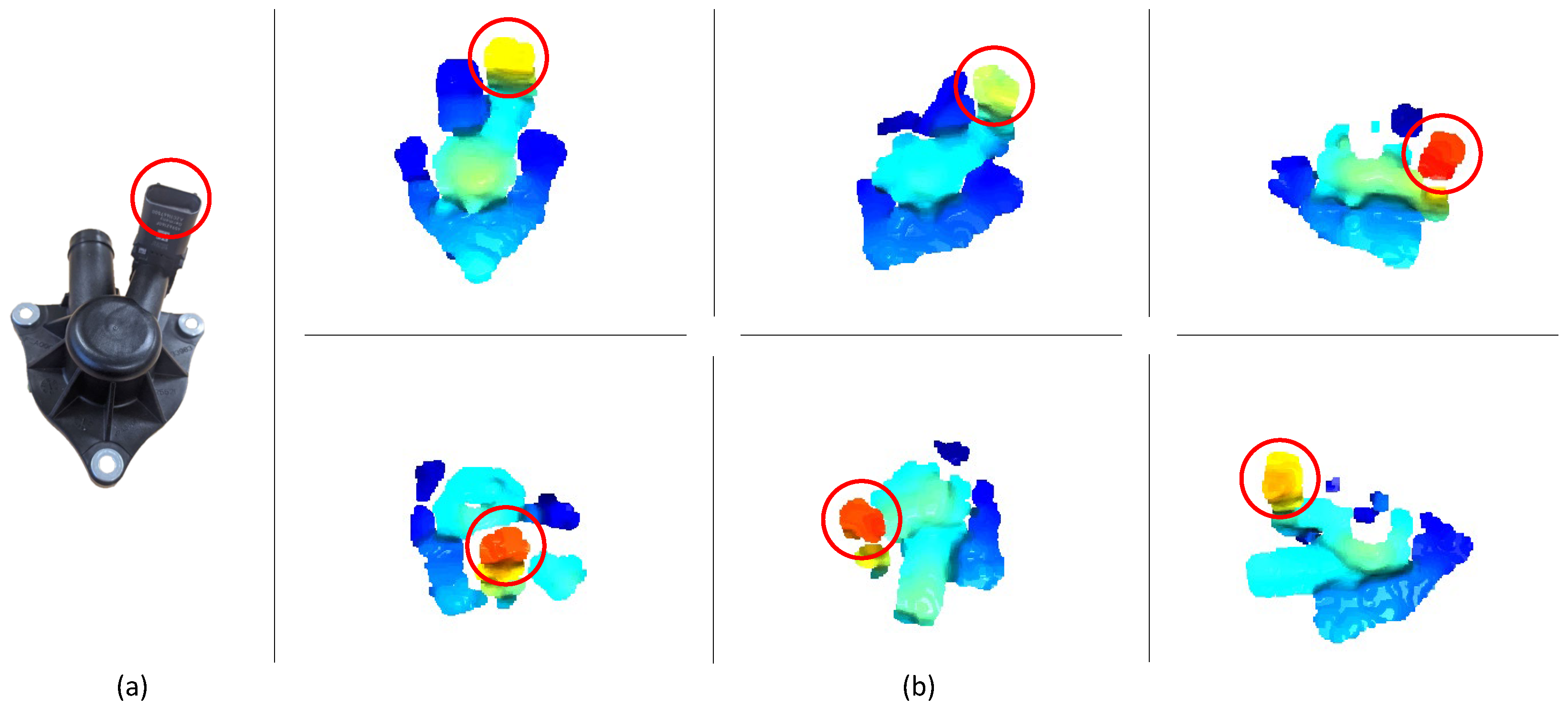
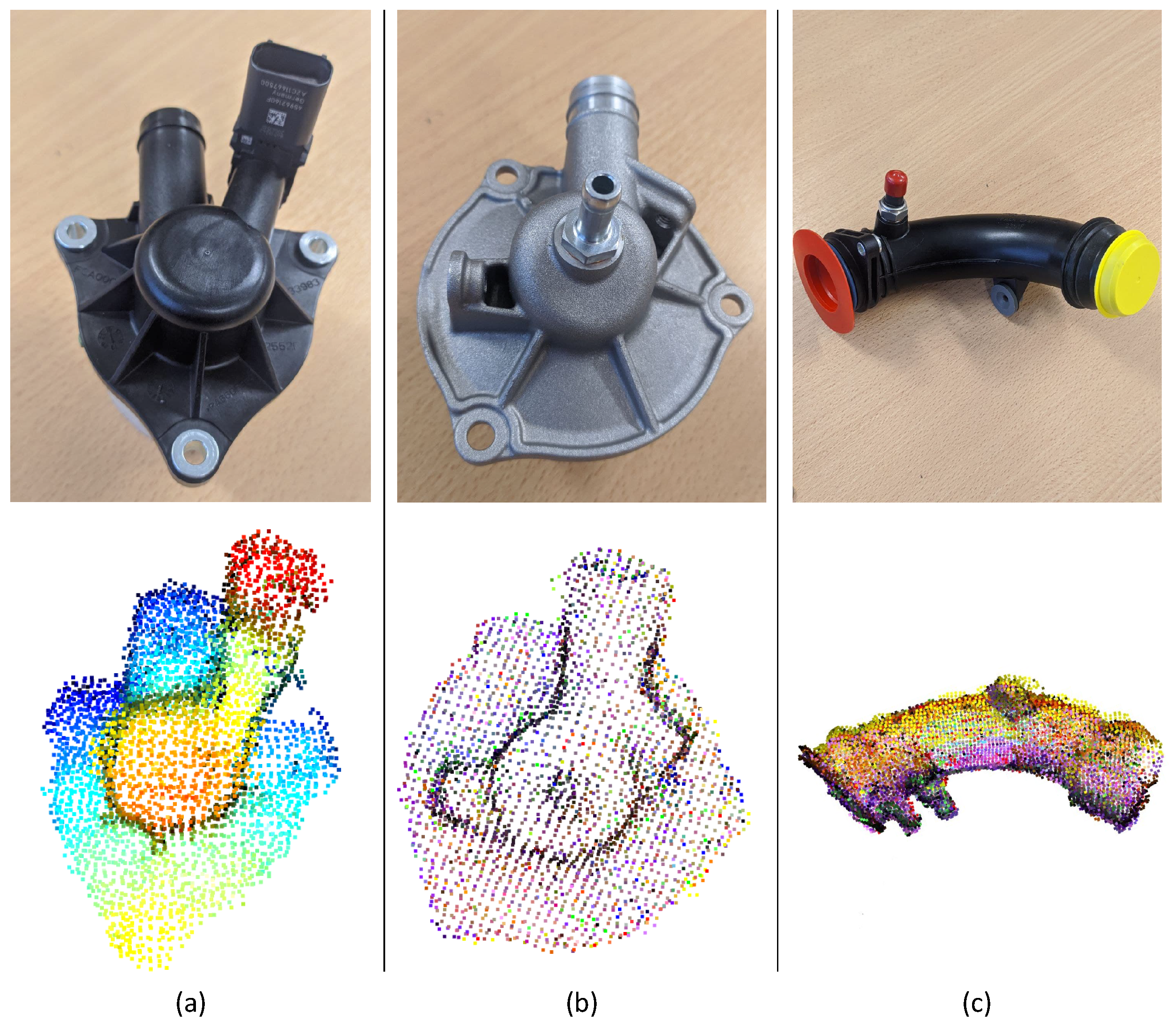
- The 3D data of the object are acquired from different points of view, e.g., by using an RGB-D camera, in order to obtain n different point clouds of various portions of the object.
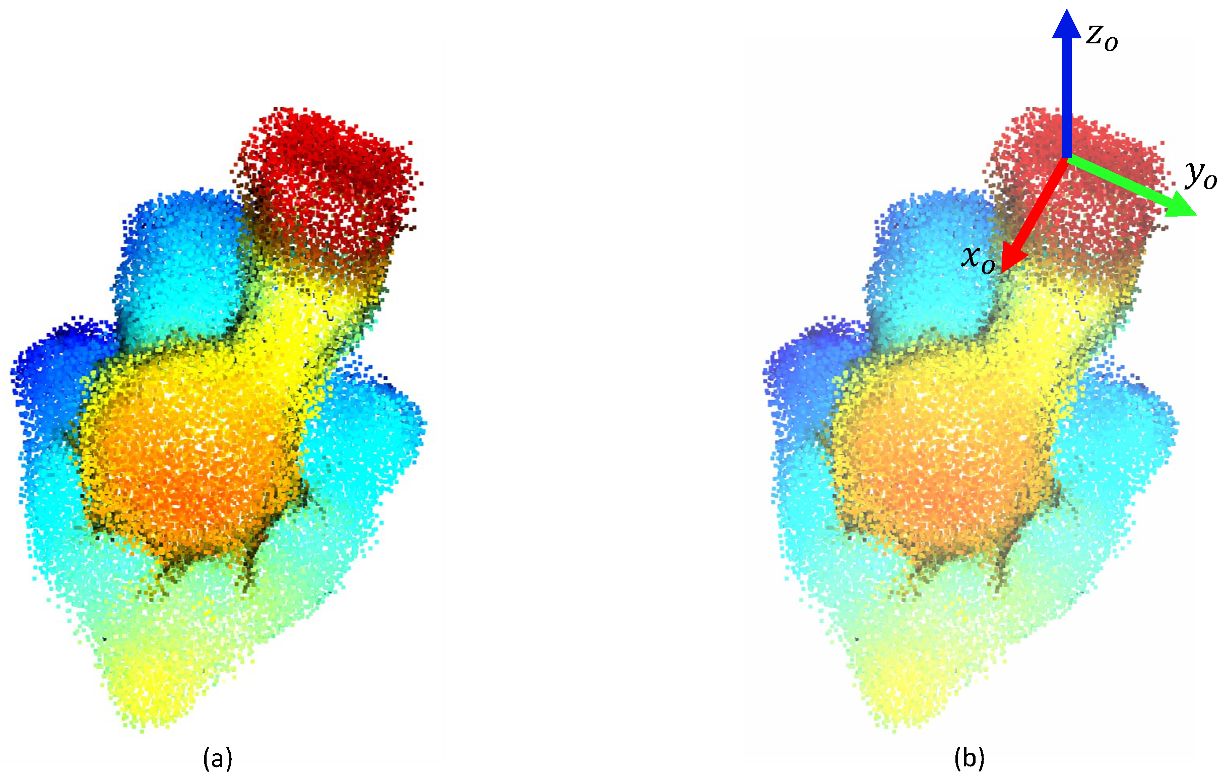
- (b)
- The point clouds are merged to obtain the model of the object surface, through a registration algorithm.
- (c)
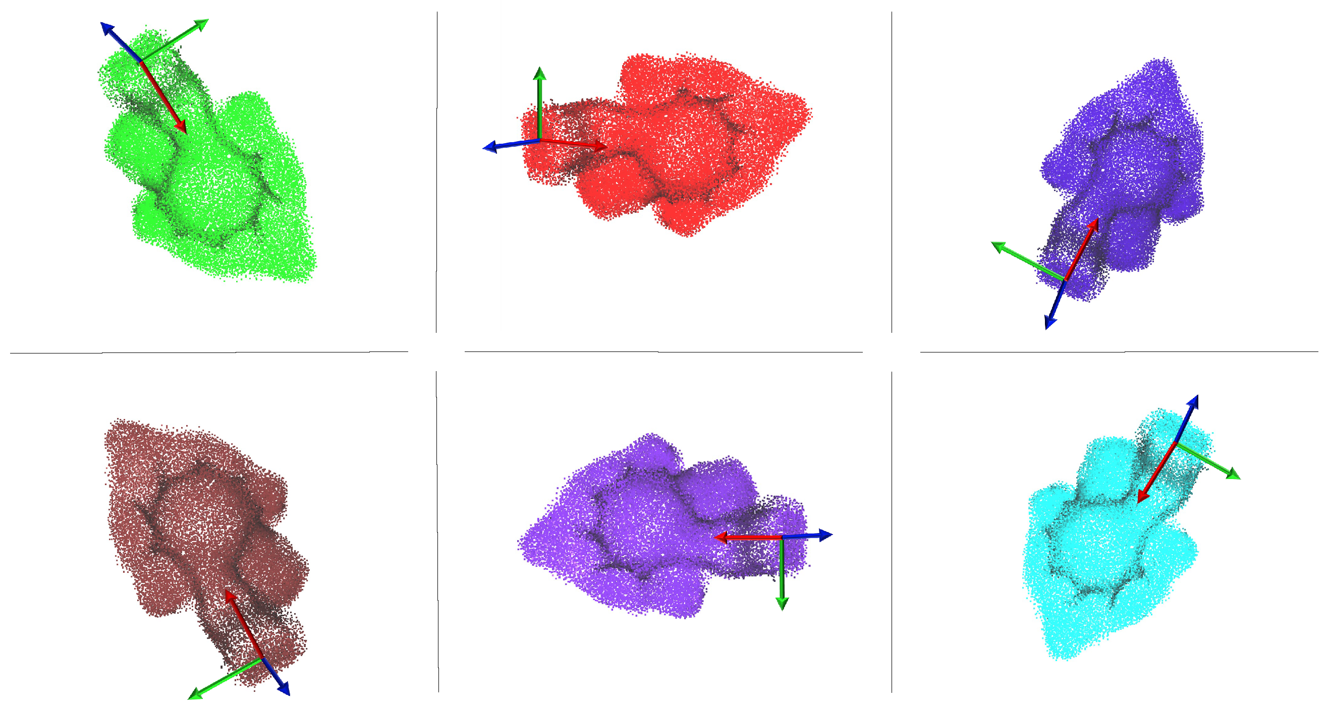
- A frame that represents the best grasping pose for the object is attached to a point of the model built in the previous step. The grasping point is selected on the basis of the object geometry and the available gripper. Since more than a grasping point can be defined for each object, the one closest to the end-effector frame is selected.
- (d)
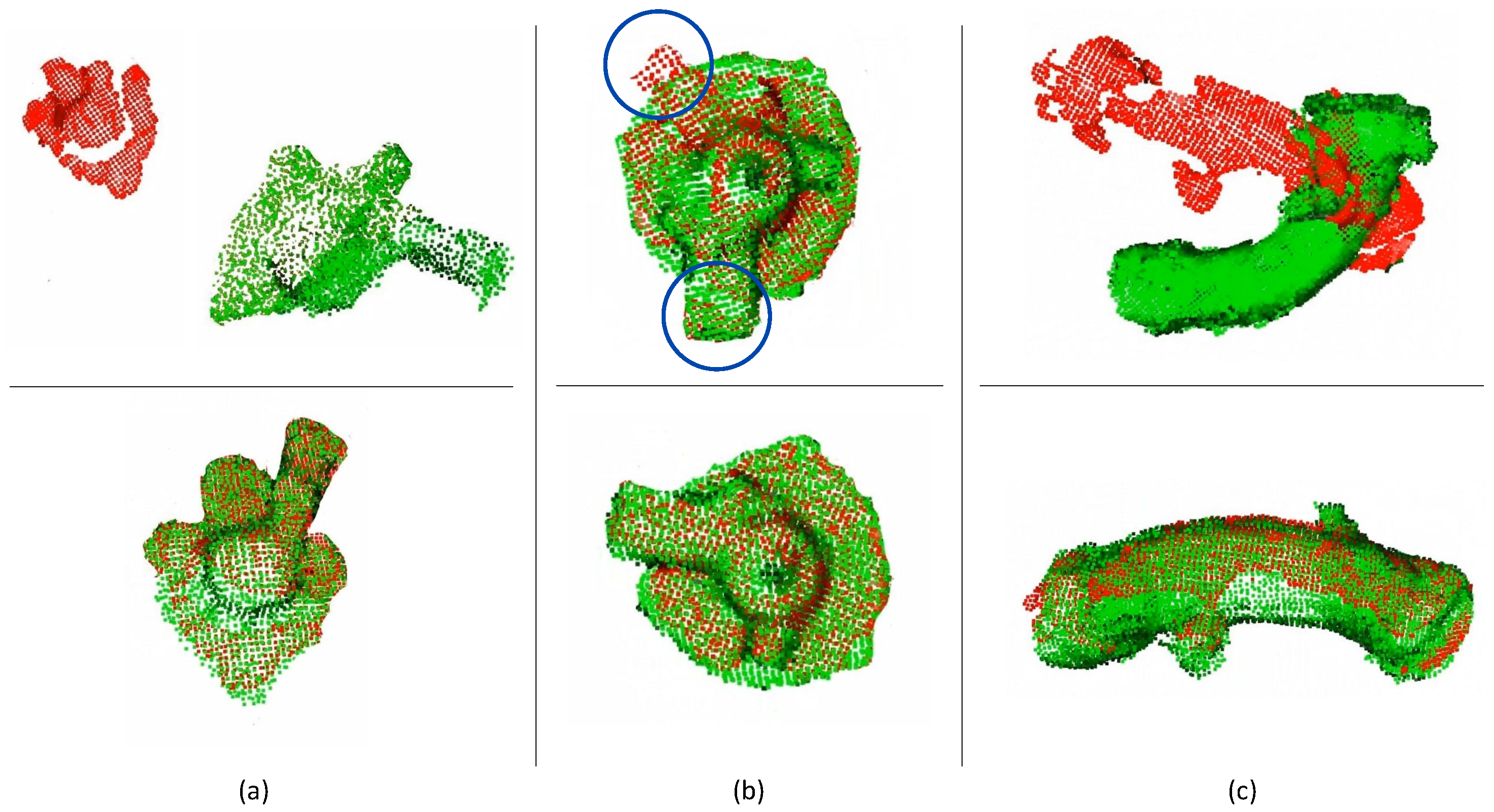
- The model is aligned to the current point cloud, in order to be able to transport the grasp pose on the current object. As a measure of the alignment, a fitness metric is computed. Thus, in the case of a bad alignment, the robot can move the camera in a new position, acquire the object point cloud from a different point of view and repeat the alignment.
- (e)
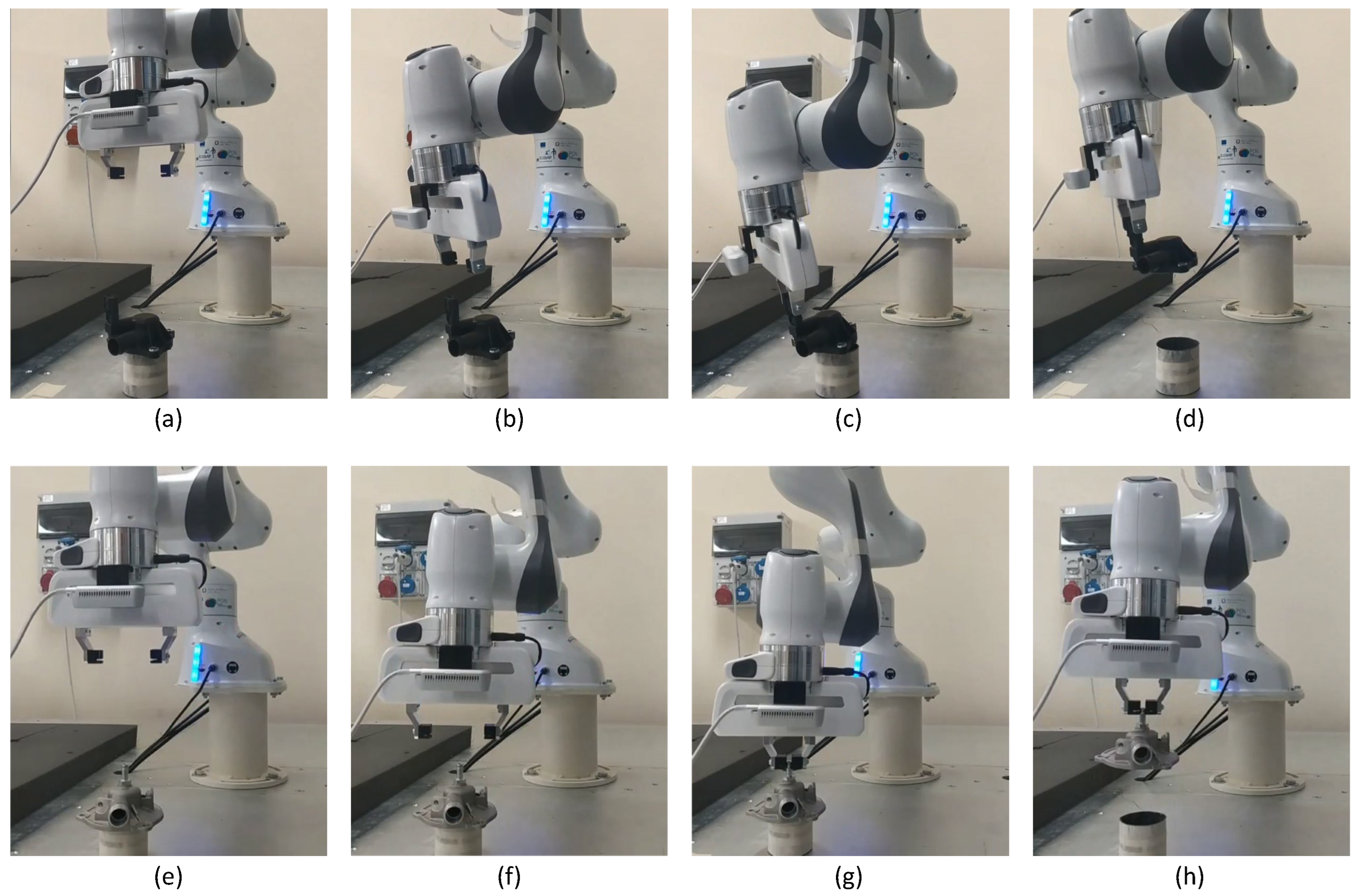
- The current grasp pose is transformed into the robot coordinates frame through the camera–end-effector calibration matrix and the robot is commanded to perform the grasp.

3.1. Object Model Reconstruction
3.2. Grasp Point Estimation
- A set of local features, called fast point feature histograms (FPFH), were extracted from each point of [35];
- The corresponding points of the two point clouds were computed by using a RANSAC (random sample consensus) algorithm [36]: at each iteration, given points randomly extracted from , the corresponding points of were the nearest with respect to the extracted features.
- The transformation matrix computed at the previous step was used as an initial guess for the ICP algorithm aimed at refining the alignment.
3.3. Grasping
4. Implementation
5. Experimental Results
- For each model orientation, a maximum number of 100 iterations was established;
- Two thresholds for the fitness were defined: threshold below which the overlap was considered failed and threshold above which the overlap was considered good enough;
- During the overlapping, if threshold was exceeded, the algorithm stopped and no further comparisons were made;
- If no overlap exceeded threshold , the one with the highest fitness was considered;
- If no overlap exceeded threshold , the algorithm reported a failure.
6. Conclusions
Author Contributions
Funding
Institutional Review Board Statement
Informed Consent Statement
Data Availability Statement
Acknowledgments
Conflicts of Interest
References
- Karabegović, I. Comparative analysis of automation of production process with industrial robots in Asia/Australia and Europe. Int. J. Hum. Cap. Urban Manag. 2017, 2, 29–38. [Google Scholar]
- Weiss, A.; Wortmeier, A.K.; Kubicek, B. Cobots in industry 4.0: A roadmap for future practice studies on human–robot collaboration. IEEE Trans. Hum.-Mach. Syst. 2021, 51, 335–345. [Google Scholar] [CrossRef]
- Ozkul, T. Equipping legacy robots with vision: Performance, availability and accuracy considerations. Int. J. Mechatron. Manuf. Syst. 2009, 2, 331–347. [Google Scholar] [CrossRef]
- Sahbani, A.; El-Khoury, S.; Bidaud, P. An overview of 3D object grasp synthesis algorithms. Robot. Auton. Syst. 2012, 60, 326–336. [Google Scholar] [CrossRef]
- Bicchi, A.; Kumar, V. Robotic grasping and contact: A review. In Proceedings of the 2000 ICRA. Millennium Conference. IEEE International Conference on Robotics and Automation, Symposia Proceedings (Cat. No. 00CH37065), San Francisco, CA, USA, 24–28 April 2000; IEEE: Piscataway, NJ, USA; Volume 1, pp. 348–353. [Google Scholar]
- Bohg, J.; Morales, A.; Asfour, T.; Kragic, D. Data-driven grasp synthesis—A survey. IEEE Trans. Robot. 2013, 30, 289–309. [Google Scholar] [CrossRef]
- Zhang, H.; Tan, J.; Zhao, C.; Liang, Z.; Liu, L.; Zhong, H.; Fan, S. A fast detection and grasping method for mobile manipulator based on improved faster R-CNN. Ind. Robot. Int. J. Robot. Res. Appl. 2020, 47, 167–175. [Google Scholar] [CrossRef]
- Morrison, D.; Corke, P.; Leitner, J. Closing the Loop for Robotic Grasping: A Real-time, Generative Grasp Synthesis Approach. In Proceedings of the Robotics: Science and Systems (RSS), Pittsburgh, PA, USA, 26–30 June 2018. [Google Scholar]
- Morrison, D.; Corke, P.; Leitner, J. Learning robust, real-time, reactive robotic grasping. Int. J. Robot. Res. 2020, 39, 183–201. [Google Scholar] [CrossRef]
- Sileo, M.; Bloisi, D.D.; Pierri, F. Real-time Object Detection and Grasping Using Background Subtraction in an Industrial Scenario. In Proceedings of the 2021 IEEE 6th International Forum on Research and Technology for Society and Industry (RTSI), Virtual, 6–9 September 2021; pp. 283–288. [Google Scholar]
- Bloisi, D.D.; Pennisi, A.; Iocchi, L. Background modeling in the maritime domain. Mach. Vis. Appl. 2014, 25, 1257–1269. [Google Scholar] [CrossRef]
- Asif, U.; Tang, J.; Harrer, S. GraspNet: An Efficient Convolutional Neural Network for Real-time Grasp Detection for Low-powered Devices. In Proceedings of the IJCAI, Stockholm, Sweden, 13–19 July 2018; pp. 4875–4882. [Google Scholar]
- Dune, C.; Marchand, E.; Collowet, C.; Leroux, C. Active rough shape estimation of unknown objects. In Proceedings of the 2008 IEEE/RSJ International Conference on Intelligent Robots and Systems, Nice, France, 22–26 September 2008; pp. 3622–3627. [Google Scholar]
- Kraft, D.; Pugeault, N.; Başeski, E.; Popović, M.; Kragić, D.; Kalkan, S.; Wörgötter, F.; Krüger, N. Birth of the object: Detection of objectness and extraction of object shape through object–action complexes. Int. J. Humanoid Robot. 2008, 5, 247–265. [Google Scholar] [CrossRef]
- Detry, R.; Ek, C.H.; Madry, M.; Piater, J.; Kragic, D. Generalizing grasps across partly similar objects. In Proceedings of the 2012 IEEE International Conference on Robotics and Automation, St. Paul, MN, USA, 14–18 May 2012; pp. 3791–3797. [Google Scholar]
- Dang, H.; Allen, P.K. Semantic grasping: Planning robotic grasps functionally suitable for an object manipulation task. In Proceedings of the 2012 IEEE/RSJ International Conference on Intelligent Robots and Systems, Vilamoura-Algarve, Portugal, 7–12 October 2012; pp. 1311–1317. [Google Scholar]
- Schmidt, P.; Vahrenkamp, N.; Wächter, M.; Asfour, T. Grasping of unknown objects using deep convolutional neural networks based on depth images. In Proceedings of the 2018 IEEE International Conference on Robotics and Automation (ICRA), Brisbane, Australia, 21–25 May 2018; pp. 6831–6838. [Google Scholar]
- Eppner, C.; Brock, O. Grasping unknown objects by exploiting shape adaptability and environmental constraints. In Proceedings of the 2013 IEEE/RSJ International Conference on Intelligent Robots and Systems, Tokyo, Japan, 3–7 November 2013; pp. 4000–4006. [Google Scholar]
- Fischinger, D.; Vincze, M.; Jiang, Y. Learning grasps for unknown objects in cluttered scenes. In Proceedings of the 2013 IEEE International Conference on Robotics and Automation, Karlsruhe, Germany, 6–10 May 2013; pp. 609–616. [Google Scholar]
- Fischinger, D.; Vincze, M. Empty the basket-a shape based learning approach for grasping piles of unknown objects. In Proceedings of the 2012 IEEE/RSJ International Conference on Intelligent Robots and Systems, Vilamoura-Algarve, Portugal, 7–12 October 2012; pp. 2051–2057. [Google Scholar]
- Klingbeil, E.; Rao, D.; Carpenter, B.; Ganapathi, V.; Ng, A.Y.; Khatib, O. Grasping with application to an autonomous checkout robot. In Proceedings of the 2011 IEEE International Conference on Robotics and Automation, Shanghai, China, 9–13 May 2011; pp. 2837–2844. [Google Scholar]
- Bellekens, B.; Spruyt, V.; Berkvens, R.; Penne, R.; Weyn, M. A benchmark survey of rigid 3D point cloud registration algorithms. Int. J. Adv. Intell. Syst. 2015, 8, 118–127. [Google Scholar]
- Nigro, M.; Sileo, M.; Pierri, F.; Genovese, K.; Bloisi, D.D.; Caccavale, F. Peg-in-hole using 3D workpiece reconstruction and CNN-based hole detection. In Proceedings of the 2020 IEEE/RSJ International Conference on Intelligent Robots and Systems (IROS), Virtual, 25–29 October 2020; pp. 4235–4240. [Google Scholar]
- Sutton, M.A.; Orteu, J.J.; Schreier, H. Image Correlation for Shape, Motion and Deformation Measurements: Basic Concepts, Theory and Applications; Springer: New York, NY, USA, 2009. [Google Scholar]
- Chen, Y.; Medioni, G. Object modelling by registration of multiple range images. Image Vis. Comput. 1992, 10, 145–155. [Google Scholar] [CrossRef]
- Valgma, L.; Daneshmand, M.; Anbarjafari, G. Iterative closest point based 3d object reconstruction using rgb-d acquisition devices. In Proceedings of the 2016 24th IEEE Signal Processing and Communication Application Conference (SIU), Zonguldak, Turkey, 16–19 May 2016; pp. 457–460. [Google Scholar]
- Shuai, S.; Ling, Y.; Shihao, L.; Haojie, Z.; Xuhong, T.; Caixing, L.; Aidong, S.; Hanxing, L. Research on 3D surface reconstruction and body size measurement of pigs based on multi-view RGB-D cameras. Comput. Electron. Agric. 2020, 175, 105543. [Google Scholar] [CrossRef]
- Lin, W.; Anwar, A.; Li, Z.; Tong, M.; Qiu, J.; Gao, H. Recognition and pose estimation of auto parts for an autonomous spray painting robot. IEEE Trans. Ind. Inform. 2018, 15, 1709–1719. [Google Scholar] [CrossRef]
- Yang, J.; Li, H.; Campbell, D.; Jia, Y. Go-ICP: A globally optimal solution to 3D ICP point-set registration. IEEE Trans. Pattern Anal. Mach. Intell. 2015, 38, 2241–2254. [Google Scholar] [CrossRef] [PubMed]
- Yang, H.; Shi, J.; Carlone, L. Teaser: Fast and certifiable point cloud registration. IEEE Trans. Robot. 2020, 37, 314–333. [Google Scholar] [CrossRef]
- Choi, S.; Zhou, Q.Y.; Koltun, V. Robust reconstruction of indoor scenes. In Proceedings of the IEEE Conference on Computer Vision and Pattern Recognition, Boston, MA, USA, 7–12 June 2015; pp. 5556–5565. [Google Scholar]
- Nigro, M.; Sileo, M.; Pierri, F.; Bloisi, D.; Caccavale, F. Assembly task execution using visual 3D surface reconstruction: An integrated approach to parts mating. Robot. Comput.-Integr. Manuf. 2023, 81, 102519. [Google Scholar] [CrossRef]
- Siciliano, B.; Sciavicco, L.; Villani, L.; Oriolo, G. Robotics–Modelling, Planning and Control; Springer: London, UK, 2009. [Google Scholar]
- Zhou, Q.Y.; Park, J.; Koltun, V. Open3D: A Modern Library for 3D Data Processing. arXiv 2018, arXiv:1801.09847. [Google Scholar]
- Rusu, R.B.; Blodow, N.; Beetz, M. Fast point feature histograms (FPFH) for 3D registration. In Proceedings of the 2009 IEEE International Conference on Robotics and Automation, Kobe, Japan, 12–17 May 2009; pp. 3212–3217. [Google Scholar]
- Li, H.; Qin, J.; Xiang, X.; Pan, L.; Ma, W.; Xiong, N.N. An efficient image matching algorithm based on adaptive threshold and RANSAC. IEEE Access 2018, 6, 66963–66971. [Google Scholar] [CrossRef]
- Tsai, R.Y.; Lenz, R.K. A new technique for fully autonomous and efficient 3 D robotics hand/eye calibration. IEEE Trans. Robot. Autom. 1989, 5, 345–358. [Google Scholar] [CrossRef]
- Franka Emika Panda. Available online: https://www.franka.de/ (accessed on 15 January 2023).
- Intel Real Sense. Available online: https://www.intelrealsense.com/ (accessed on 23 December 2022).


| Test | ||||||
|---|---|---|---|---|---|---|
| 1 | 1.964 | 5.316 | 5.858 | 0.293 | 0.084 | 0.273 |
| 2 | 4.759 | 1.076 | 4.006 | 0.176 | 0.123 | 0.233 |
| 3 | 8.460 | 1.400 | 1.040 | 0.048 | 0.116 | 0.237 |
| 4 | 0.600 | 0.380 | 0.000 | 0.304 | 0.072 | 0.142 |
| 5 | 2.260 | 2.300 | 8.200 | 0.392 | 0.263 | 0.130 |
| 6 | 0.310 | 3.320 | 6.433 | 0.169 | 0.489 | 0.083 |
| 7 | 5.011 | 1.637 | 5.641 | 0.133 | 0.171 | 0.164 |
| 8 | 4.989 | 1.151 | 4.758 | 0.219 | 0.146 | 0.230 |
| 9 | 1.240 | 1.331 | 5.402 | 0.202 | 0.065 | 0.155 |
| 10 | 4.373 | 0.095 | 10.515 | 0.016 | 0.170 | 0.107 |
| 11 | 5.966 | 1.398 | 3.785 | 0.101 | 0.019 | 0.179 |
| 12 | 1.442 | 4.579 | 5.702 | 0.104 | 0.052 | 0.189 |
| 13 | 4.529 | 1.033 | 10.044 | 0.048 | 0.115 | 0.099 |
| 14 | 2.042 | 1.057 | 3.729 | 0.092 | 0.033 | 0.113 |
| 15 | 3.533 | 1.509 | 2.023 | 0.110 | 0.088 | 0.166 |
| 16 | 2.202 | 5.128 | 3.623 | 0.084 | 0.154 | 0.043 |
| 17 | 4.798 | 3.496 | 7.289 | 0.066 | 0.019 | 0.216 |
| 18 | 7.122 | 2.755 | 13.521 | 0.012 | 0.254 | 0.146 |
| Mean error | 3.644 | 2.164 | 5.643 | 0.143 | 0.135 | 0.161 |
| Standard deviation | 2.219 | 1.542 | 3.299 | 0.103 | 0.110 | 0.059 |
| Test | ||||||
|---|---|---|---|---|---|---|
| 1 | 1.143 | 3.243 | 13.409 | 0.039 | 0.015 | 0.133 |
| 2 | 3.157 | 2.066 | 10.148 | 0.005 | 0.051 | 0.146 |
| 3 | 0.852 | 6.250 | 4.402 | 0.013 | 0.042 | 0.291 |
| 4 | 8.063 | 7.524 | 0.843 | 0.024 | 0.017 | 0.018 |
| 5 | 6.522 | 4.445 | 7.708 | 0.012 | 0.019 | 0.053 |
| 6 | 2.922 | 0.093 | 5.704 | 0.024 | 0.005 | 0.068 |
| 7 | 1.727 | 2.234 | 6.592 | 0.013 | 0.002 | 0.096 |
| 8 | 0.379 | 1.559 | 11.784 | 0.013 | 0.026 | 0.009 |
| 9 | 7.802 | 1.887 | 7.063 | 0.060 | 0.091 | 0.054 |
| 10 | 8.114 | 0.677 | 8.383 | 0.023 | 0.054 | 0.028 |
| 11 | 2.548 | 1.079 | 8.268 | 0.002 | 0.040 | 0.079 |
| 12 | 2.814 | 2.884 | 6.487 | 0.169 | 0.003 | 0.183 |
| 13 | 0.816 | 0.460 | 13.407 | 0.017 | 0.024 | 0.157 |
| 14 | 5.874 | 0.002 | 7.367 | 0.070 | 0.189 | 0.073 |
| 15 | 9.727 | 0.415 | 2.165 | 0.001 | 0.105 | 0.000 |
| 16 | 5.761 | 0.153 | 9.530 | 0.038 | 0.101 | 0.012 |
| 17 | 4.702 | 3.785 | 0.587 | 0.091 | 0.082 | 0.027 |
| 18 | 5.360 | 2.653 | 7.143 | 0.002 | 0.029 | 0.051 |
| Mean error | 4.349 | 2.301 | 7.277 | 0.034 | 0.050 | 0.082 |
| Standard deviation | 2.845 | 2.077 | 3.616 | 0.041 | 0.047 | 0.073 |
Disclaimer/Publisher’s Note: The statements, opinions and data contained in all publications are solely those of the individual author(s) and contributor(s) and not of MDPI and/or the editor(s). MDPI and/or the editor(s) disclaim responsibility for any injury to people or property resulting from any ideas, methods, instructions or products referred to in the content. |
© 2023 by the authors. Licensee MDPI, Basel, Switzerland. This article is an open access article distributed under the terms and conditions of the Creative Commons Attribution (CC BY) license (https://creativecommons.org/licenses/by/4.0/).
Share and Cite
Sileo, M.; Bloisi, D.D.; Pierri, F. Grasping of Solid Industrial Objects Using 3D Registration. Machines 2023, 11, 396. https://doi.org/10.3390/machines11030396
Sileo M, Bloisi DD, Pierri F. Grasping of Solid Industrial Objects Using 3D Registration. Machines. 2023; 11(3):396. https://doi.org/10.3390/machines11030396
Chicago/Turabian StyleSileo, Monica, Domenico Daniele Bloisi, and Francesco Pierri. 2023. "Grasping of Solid Industrial Objects Using 3D Registration" Machines 11, no. 3: 396. https://doi.org/10.3390/machines11030396
APA StyleSileo, M., Bloisi, D. D., & Pierri, F. (2023). Grasping of Solid Industrial Objects Using 3D Registration. Machines, 11(3), 396. https://doi.org/10.3390/machines11030396