1. Introduction
The current state and progress in the area of industrial systems is affected by the implementation of the Industry 4.0 concept in all areas of technical practice. According to the ideas mentioned in the Industry 4.0 concept [
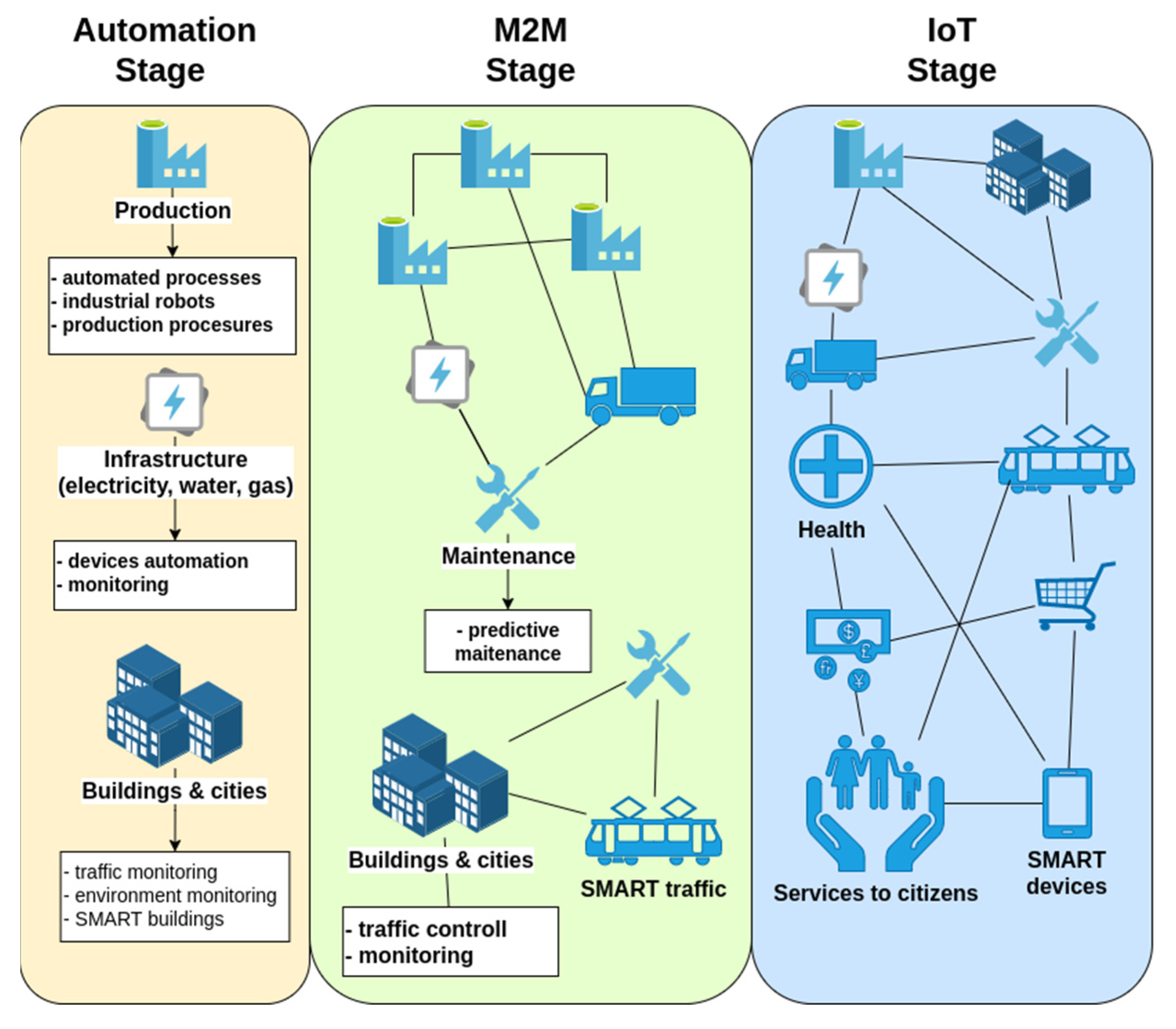
1], the goal is to design and implement intelligent and self-organizing production. This goal can be achieved using the combination of a modern information infrastructure with intelligent autonomous production systems. In addition, there is the impact of globalization on production. In modern production systems, it is necessary to provide access to the systems and production devices using the Internet, while they are isolated by default in classical production systems. One of the key elements of the Industry 4.0 concept is the Smart Factory (SF) [
2]. The entire production system of this kind is made up of devices capable of evaluating measured values and communicating with other devices in its vicinity or using the Internet around the world. From the point of view of communication, these objects contain all layers of the ISO/OSI model (ISO/IEC 7498-1/4)—RM OSI, including the application layer, which enables the execution of various applications in the device’s memory. In the case of non-authorized access to such type of smart equipment, there is a possibility to create a number of applications with various malicious purposes—network scanning, denial of important services, password stealing, etc. The range of possibilities is quite wide, and the damage caused in this way can be fatal. The terms Internet of Things and Edge computing are generally used in the technical literature. In automation networks, the name IoT, due to the requirements for higher security, reliability, and responsiveness than for conventional IoT devices, is replaced with the name Industrial Internet of Things (IIOT) [
3]. Both systems use the same forms of data transfer and the same method of architecture. The main difference between the IoT and IIoT systems is primarily in the possibility of better device management and a higher level of security that the IIoT processes provide. The implementation of the methodology to increase security is a basic condition for the implementation of IIoT systems. With the use of the presented rules for wireless communication of systems, it is possible to increase the overall level of security of IoT elements to a level suitable for use within the Smart Factory.
Regardless of the form of communication, high-quality data transmission in an industrial environment has a fundamental impact on the quality of management, and this affects the smoothness of the production process. Therefore, it is very important to limit the possibility of external disruption to systems and violation of their communication and the entire production process by an unauthorized person. This is also the aim of this work. The main importance of this publication lies in the creation of a universally applicable methodology and procedures for the implementation of security policy within such production systems, taking into account different architectures of production systems and forms of communication. An important part of the work is the specification of communication protocols used in automation, their distribution, the advantages and disadvantages of individual forms of data transmission, and the impact of their use on the overall level of security of industrial systems. Although technologies such as IoT and wireless communication are still only partially used in production practice, currently, wire communication is still the main form of transmission of data and control information.
Furthermore, this work describes the way to implement the architecture of modern production processes considering modern forms of communication. Taking into account the assumed flexibility of production elements and the entire production process in modern production enterprises, the future of industrial communication is mainly about wireless communication in various forms, including its issues. The proposed methodological instructions can be universally applied not only in classic production processes but also in the design of securing the production process of the Smart Factory type on the Internet and wireless communication within the IoT environment.
It is clear that the implementation of safety rules and security principles in Smart Factory systems is necessary, and implementation is greatly complicated by a large number of communication protocols in use at the same time and by the fact that in modern cybernetic systems, often a wireless form of data transmission is preferred. It is also clear that the communication subsystem must be capable of guaranteeing a high transmission capacity and ensuring a high level of reliability and trustworthiness, and it is clear that any wireless form of data transmission is more susceptible to transmission failures and data compromise than metallic and optical communication paths.
So, the key elements of the proposed scheme are:
A clear and simple defined set of rules to achieve a reliable, secure, and technically relevant form of data exchange in all layers of production systems.
A defined set of rules for the implementation of both horizontal and vertical separation of the production process, especially for wireless communication.
The suggested procedure is applicable regardless of the protocol type and the method of communication.
The proposal reflects the appropriate standards in the area of cybernetic security.
Part of this contribution is an example of the application in the model situation.
The problem area of data and cyber security is the subject of a number of available publications. Some authors solve specific narrowly focused problems in the field of security of cybernetic systems, whereas others offer a comprehensive view of the overall approach to security. Among the works that deal with the issue of security in industrial networks globally is the work of the author Ackerman [
4], who in his publication is devoted to the analysis of possible attacks in the industrial control system environment, the security of individual automation protocols, and possible protection against them. The publication also includes instructions for determining risks for individual subsystems, including the specification of the directions on how to develop a security program in a cybernetic system, including rules of industry-adopted common standards. A publication with a very similar scope and focus is the work of the author Krutz [
5]. It describes the issue of cyber security of production systems from the point of view of finding analogies of production communication systems with IT networks, focusing on security and the use of TCP/IP in the industrial automation environment. In addition, it describes the use and security of technologies such as BIG DATA and IIoT within the cyber–physical system and their impact on the safety of critical infrastructure. The author Flaus Jean-Marie [
6] uses a similar description of cyber security in his work. He deals with the issue of security from the point of view of possible attacks on individual components of cyber–physical systems and vulnerabilities in communication protocols and defines methods and tools to secure industrial control systems and specifies the meaning and position of the DMZ zone within the cyber–physical system, together with the application stateful firewall. In addition to the works that deal with the security of industrial systems globally and on a wider scale, there are many works that describe in detail some specific problems in the field of security of modern industrial systems. The security of IoT [
7] and wireless systems are very popular in the literature, while various progressive technologies such as blockchain [
8], artificial intelligence [
9,
10,
11], and others are used to protect them. In the [
10] publication, the author monothematically specializes in the field of IIoT. The book contains a description of the security of wireless communication within the Industrial Internet of Things and describes the entire gamut of IIoT security and practical techniques to build and adopt secure IIoT solutions. In [
12], the authors propose a novel algorithm to identify network errors and anomalies in IoT networks, which uses IDS together with machine learning. The authors Abbas et al. [
9] investigate different attacks on IoT systems and solve the safety and security of IoT systems using machine learning techniques. The use of blockchain technology in IoT networking describes the contribution [
8]. The authors are solving the problem of server authorization in the LoRaWAN communication network. The core of the article is a proposal for a security model for firmware distribution. Another security problem in LoRaWAN communication is elaborated in [
13]. The contribution offers an improvement to the design of the LoRaWAN security model for trusted key management. Generally, wireless communication has considerable reserves in terms of security, and many other authors deal with a similar issue [
7,
14,
15,
16,
17,
18,
19].
In addition to wireless communication, many works are devoted to the security of automation systems and the security of communication within industrial systems. Classic automation protocols are out of the main interest. In principle, they are incapable of communicating outside of the local production process, and communication safety can be ensured physically just by preventing access [
5]. These are mainly modern protocols, capable of communication using TCP/IP and the Internet, such as Ethercat [
20], Modbus/TCP [
21], and OPC-UA [
22], where it is necessary to address communication security. However, the field of industrial system communication security is broad but well-researched [
23,
24,
25].
A special approach to cyber security issues within the concept of Industry 4.0 is worth mentioning, as is represented in the work of Petrenko [
26], who suggests the implementation of immune protection of the Industry 4.0 cybernetic system and suggests the mathematical framework for the immune and self-healing cyber–physical system.
The results in the literature indicate that the area of cybersecurity is extremely important and is undergoing rapid development. In this paper, we focus on the implementation of a method for creating a securely communicating cyber factory in compliance with relevant standards and generally known rules, universally applicable in practice in the design and implementation of modern production facilities.
The procedure for solving the issue of securing such complex systems as Smart Factory and similar cyber systems is complicated. The sequence of steps in this work can be divided into several phases. The first step is the analysis of the current state within the cyber security of cyber–physical systems, mainly from the point of view of the state of security in currently used communication protocols. The next steps are the specification of a possible solution method based on known facts, and then, in the final part, the phase of designing a suitable solution method. Due to the specific situation within production systems, where each solution is unique, the outputs do not contain specific data from the real production system.
3. Cybernetic Systems Communication Protocols
The communication in Smart Factory systems, along with different ways of organizing architecture, is implemented using a number of communication protocols. In a simplified form, they can be relatively easily divided into three significant groups.
They are as follows:
Classic (proprietary) automation protocols, e.g., HART, ProfibusPA, ProfibusDP, DeviceNet, CAN, CAN Open, Modbus, Modbus Plus, Foundation Fieldbus, ASI, Lon Works, and HART;
Industrial protocols based on ethernet, e.g., Profinet, EtherNet/IP, Modbus TCP, EtherCAT, DNP, BAC Net, Sercos III, and TSN;
Wireless protocols (often used in the IoT environment), e.g., BLE, Z-wave, ZigBEE, WirelessHART, 6LoWPAN, IEEE 802.11.xx, and LoraWAN;
Application protocols used for communication within Smart Factory, e.g., MQTT, CoAP, AMQP, DDS, HTTP, and OPC UA.
The given list does not include all kinds of protocols that are actually applied in different implementations. The field of data transmission within industrial systems in wired or wireless form is quite complex, and thus the number of protocols and sub-protocols actually used within different parts of production systems is considerable.
In the case of classic protocols, manufacturers rely on proprietary solutions for transmission (proprietary developed connectors, specific media, defining the entire physical layer, and controlling the transmission of individual bits). The main problem of classic communication protocols is the low level of compatibility. The security of classic protocols is well developed and, due to the absence of compatibility with the Internet, they are very well protected.
3.1. Industrial Protocols Based on Ethernet
The category of Ethernet industrial protocols uses existing technologies known from information systems. The data transmission within the first and second layers of the RM OSI model (physical + line layer) in this case is provided by the well-known Ethernet protocol (the set of IEEE 802.3xx standards—
www.ieee802.org (accessed on 11 December 2022) and for the transmission of information within the third and fourth layers of the OSI model, the TCP/IP protocol is used as an intermediary [
35]. The resistance against threads is lower than the resistance of classic protocols, but this is the price of compatibility.
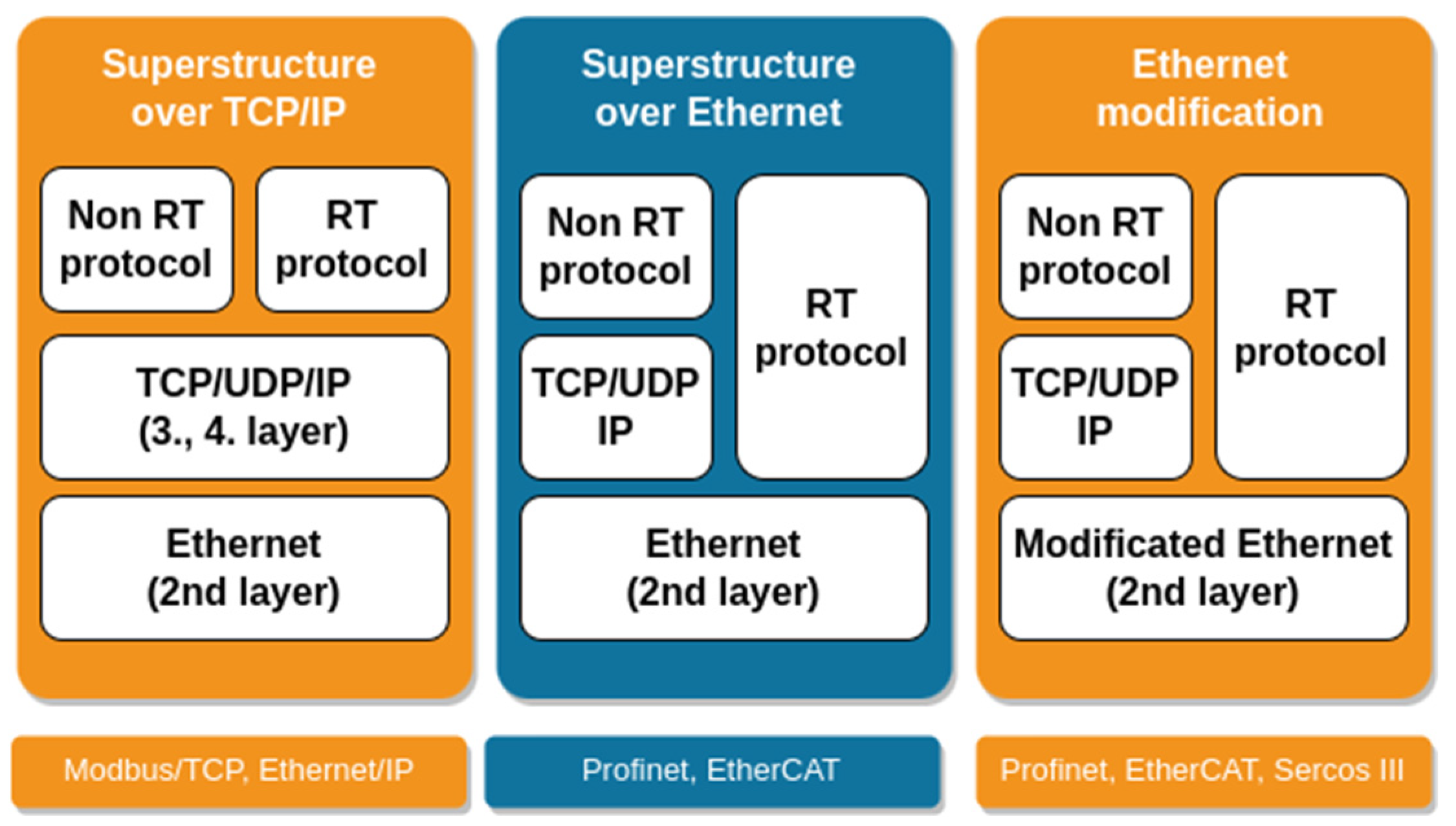
Ethernet industrial protocols often extend TCP/IP/Ethernet communication with additional services [
36], and according to the level of use of TCP/IP, it is possible to divide into three groups:
Superstructure on top of TCP/IP;
Superstructure over Ethernet communication;
Modification of Ethernet communication.
The Profinet protocol has a special meaning to the mentioned protocols (probably the most important in our conditions). This is due to its high penetration in the industry caused by the number of supported systems and a wide range of manufacturers. It is suitable for data communication using industrial Ethernet and is intended for data collection and device control in industrial systems with different access times, in the fastest version close to 1ms (three standards):
TCP/IP transmissions, reaction time approx. 100 ms;
Real-Time Profinet (RT), reaction time 10 ms (10 ms cycle);
IRT Profinet, reaction time 1 ms (1 ms cycle).
The operation of Profinet TCP/IP and RT is based on communication using the Ethernet protocol on the data link layer RM OSI. While the first uses the full services of the TCP/IP protocol, the second (RT) achieves a faster response by bypassing the TCP and IP protocols in the RM OSI network and transport layers (
Figure 4). However, the mentioned solution has the disadvantage that it is not possible to route packets between networks using the RT protocol. The use of protocols is then as follows: Profinet TCP/IP is used for configuration and diagnostics or communication from the local network to the other networks (outside). The Profinet RT protocol runs on the same hardware, but thanks to its faster response, its task is to transfer messages between devices within the local network.
The data transmission process consists of gradual encapsulation from the application layer to the network layer, where the data transfer continues with the transfer and addressing of devices within the local network with the data link protocol for data delivery within the physical layer—Ethernet. The Ethernet protocol is a widely used communication scheme generally in many other cases.
The last-mentioned protocol, the IRT Profinet protocol, is the fastest. The disadvantage is that it requires specialized hardware for its operation (due to the need to process a non-standard data link layer header, as shown in
Figure 5).
A 2-byte “Ethertype” variable is used to identify individual packet types. For RT transmissions, this value is set to the hexadecimal value of 0x8892. The link frame includes the physical address of the destination and source communication node, the data itself, and the checksum.
The Profinet protocol is very well-known and widely used, so it is presented here as an example of a solution for encapsulating data transmission services within cybernetic systems into classical (Internet) transmission systems using available protocols and services. According to this scheme, every modern industry protocol uses the data link layer protocol in a similar way. All the mentioned protocols use the IP layer for device addressing (IP protocol). Some industrial protocols use only TCP to transfer data (Modbus TCP), some use both TCP and UDP (EtherNet/IP), and one (Profinet) uses TCP while having another form of communication that bypasses the TCP/IP layer. This approach eliminates the main disadvantage of classic TCP/IP + ethernet networks: the impossibility of deterministic communication and the impossibility of RT transmission within the network (
Figure 6).
Communication between objects is the basis of implementation in modern cybernetic systems, while the focus is on compatibility with other systems. Therefore, the inevitable trend is to reduce the implementation of classic automation protocols and replace them with protocols compatible with the surrounding environment.
The definition ‘compatibility with other systems’ is mainly meant by the Internet, which is built primarily on the TCP/IP protocol. This effort results in two facts. The first (positive) is the fact that the implementation of TCP/IP within industrial systems results in better compatibility with the surrounding environment. The second fact (negative) is the same from another point of view. The increase in compatibility directly causes a decrease in the data security of industrial systems. This is an important factor, especially for Smart Factory systems and all modern cybernetic systems, where communication is a basic prerequisite for successful implementation.
3.2. Application Protocols in Automation
The communication and data transfer using application protocols can be assigned to the application layer of the RM OSI model (ISO/IEC 7498-1/4). The data transfer directly depends on TCP/IP + Ethernet protocol services. The data of these protocols are transmitted in the “DATA” area of the TCP packet, or in the “DATA” field of an IP datagram. The entire addressing (data delivery) is therefore absolutely dependent on the TCP/IP model. Part of the TCP/IP protocol family is the UDP sub-protocol, which is a simpler implementation of the TCP protocol and creates connectionless communication within the Internet and data networks. The two most used relevant application layer protocols used in cybernetic systems (IoT systems) are AMQP and MQTT [
4]. Both protocols are very similar—to work they require TCP/IP and belong to the application layer of the RM OSI model. In addition to those listed, other protocols with a similar functional principle are used in IoT networks, i.e., CoAP, DDS, XMPP, and OPC UA [
10,
37,
38].
A special case within the mentioned protocols is a relatively frequently used communication standard OPC UA—Open Platform Communication Unified Architecture [
39]. The core of OPC UA is technologies OLE, COM, and DCOM designed by Microsoft Corporation. The main idea of OPC UA is to maximize the compatibility of communication between proprietary control systems and elements of industrial networks of different manufacturers. Of course, with a sufficient level of security. Due to these properties, it is a very commonly used communication framework, especially in modern cybernetic systems and IoT communication networks. The OPC UA protocol is not directly intended to manage time-dependent processes, but rather serves to collect data from the production process and transfer information between individual objects in the production process [
40]. There exist some ideas on how to improve the response time of the OPC UA protocol [
41], use OPC UA in a real-time production control environment [
17], and even direct real-time process control at the lowest level [
42]. However, in a real environment, other proven and more stable forms of communication are currently preferred for managing real-time processes.
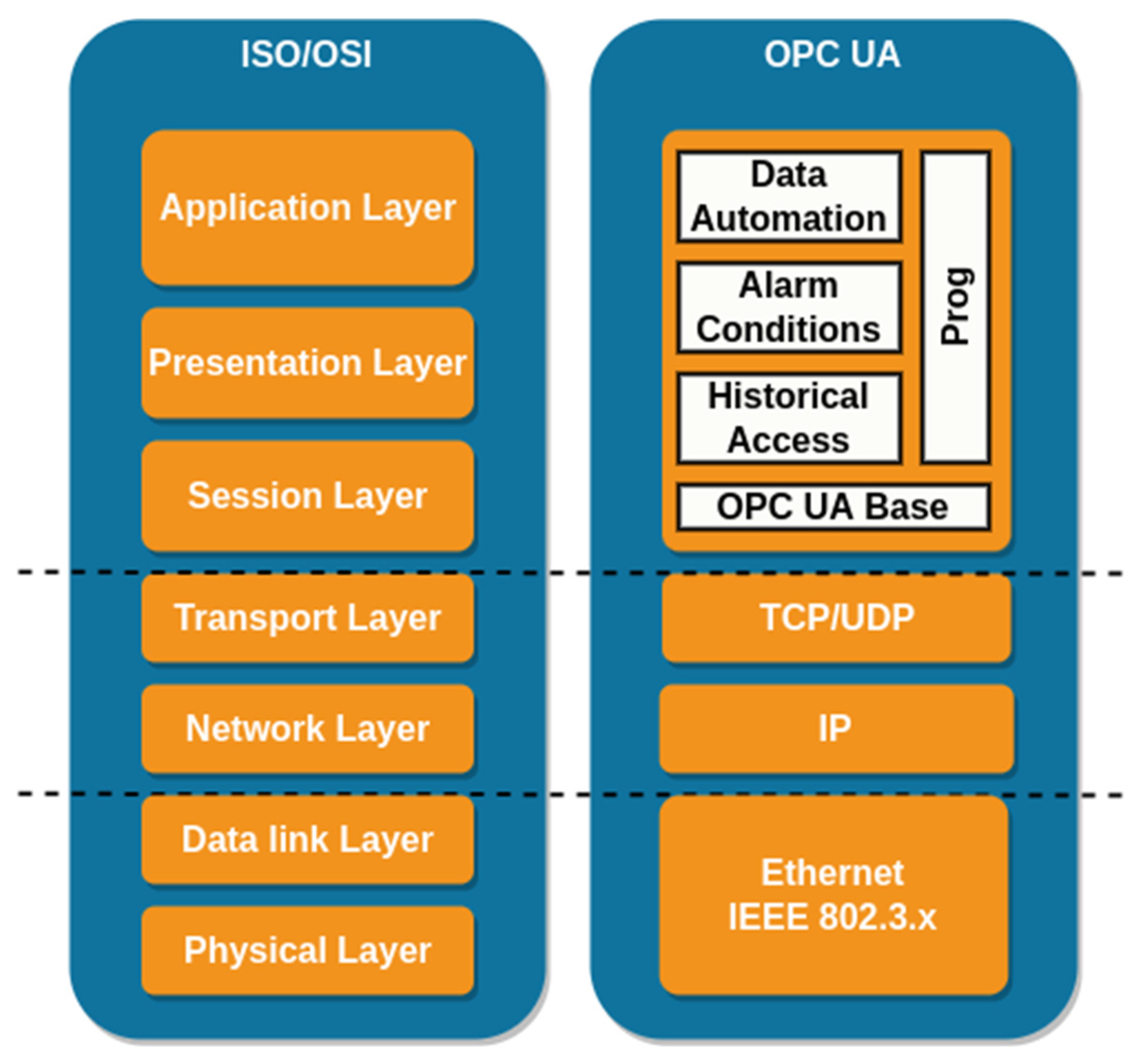
The OPC UA protocol is an open platform-independent communication standard supported by the OPC Foundation and is defined by IEC 62541. From a network communication classification, it is an application protocol, as well as the above-mentioned protocols, with the entire communication stack built in the OPC UA application layer and supplemented with TCP/IP protocol services for the third and fourth layers, or Ethernet on the data link and physical layer (
Figure 7).
The OPC UA security model is at the standard level, so user authentication and rights allocation within the system are possible. Applications running within the network are authorized in the same way as individual clients. Encryption of communication is implemented in the form of asymmetric encryption with a key length of 1024–2048 bits, which is currently considered sufficient protection, although a key with a size of 2048 bits is at the limit of security. Another factor that affects the security level of the OPC UA is the centralization of the certificate management.
3.3. Wireless Communication Protocols
The inclusion of wireless communication and IoT devices in industrial communication networks means increased risks for enterprises. The primary reason is obvious: it is impossible to prevent unauthorized access to the transmission medium. A secondary problem is caused by the nature of IoT technology today. There is considerable development in this area, and a number of new devices and technical solutions have been created. This results in the creation and development of new communication protocols. Some protocols used in IoT or wireless communication mentioned in the previous section can also be included among solutions proven in practice. For example, the year of publication of the IEEE 802.15.4 standard is 2003. The BLE, ZigBee, Z-wave, WirelessHART, and 6LoWPAN protocols were created within the standard. These are among the proven and reliable forms of communication. However, there are also much newer protocols that are actually used in practice. An example is LoraWAN, specified within the LoRa Alliance (
www.lora-alliance.org) in 2015, or LTE-MTC, NB-IoT [
16] defined in 2016. It is definitely not possible to include these communication standards among solutions that have been sufficiently proven in practice. Combined with the impossibility of preventing access to the transmission medium, the result is obvious that wireless and IoT communication within cyber systems poses a significant security risk in terms of communication security. From another point of view, wireless communication is the cornerstone of information transfer within the Smart Factory. The only way is to use verified and safe types of communication protocols.
The IEEE organization deals with the specification of communication standards, while wireless communication is included in the set of standards under the heading IEEE 802.11.x to IEEE 802.15.x. In the field of IoT communication, standards based on IEEE 802.15.4 are most used, that is Bluetooth (Bluetooth Low Energy—BLE), [
43], Z-wave [
44], ZigBee [
45], WirelessHART and ISA 100.11a [
46,
47], or WiFi (IEEE 802.11x). Several other standards are related to the application of wireless technologies in the Smart Factory environment (modern cybernetic production systems are made up of a number of local systems communicating with each other and communication towards other Smart Factories using WAN networks). Within IEEE 802.15.x, there are 10 subgroups for wireless communication [
18], which include the entire issue of connectivity within wireless communication (band allocation, modulation method, frequencies, etc.). As mentioned above, there are a number of protocols commonly used in IoT systems.
The following list clearly shows the most used technologies and communication protocols within the individual functional layers for IoT:
Management of communication infrastructure: 6LowPAN, IPv4, IPv6, RPL;
Object identification in the network: EPC, uCode, I-Code, IPv6, URI, ILNP, UPnP, and SSDP;
Data transfer protocols: WiFi (IEEE 802.11 a/b/g/n/ac/ax), Bluetooth, LPWAN (NB-IoT, LoRaWan, Sigfox), ZigBEE, Z-Wave, XMPP, and LTE;
Network object discovery: Physical Web, mDNS, and DNS-SD;
Data exchange protocols: MQTT, CoAP, AMQP, Websocket, Node, and DDS;
Device management: TR-069, OMA-DM, and LWM2M;
System semantics: JSON-LD, Web Thing Model;
Multilayer Frameworks: Alljoyn, IoTivity, Weave, and Homekitbullet.
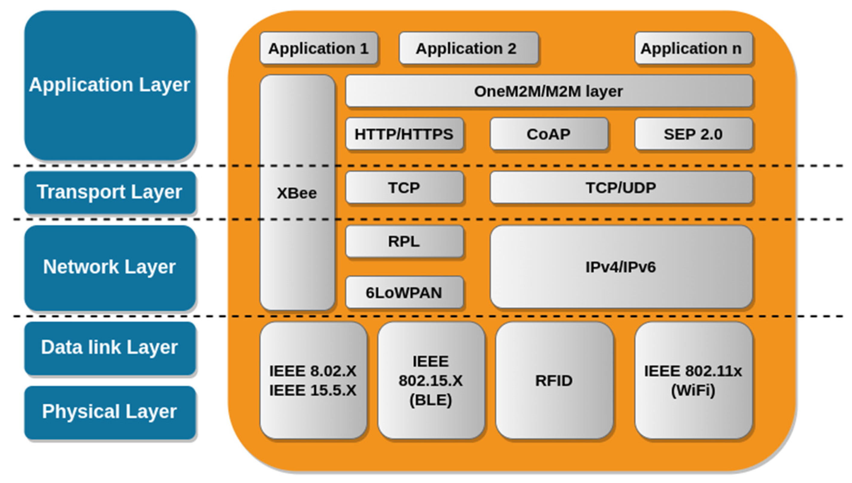
The most used IoT protocols and their position within the layers of the RM OSI model [
3] are shown in the
Figure 8:
Application layer: REST API, JSON-IPSO objects, and binary objects (BOs, BLOs);
Transport layer: CoAP, MQTT, XMPP, AMQP, LLAP, DDS, SOAP, UDP, TCP, and DTLS;
Network layer: 6LoWPAN, IPv6, IPv4, uIP, and NanoIP;
Datalink layer: IEEE 802.15.4, IEEE802.11x, ISO/IEC 18092:2004, NB-IoT, EC-GSM-IoT, Bluetooth, ANT, ISA 100.11a, EnOcean, and LTE-MTC.
In the communication scheme used in the Smart Factory environment, the framework of the IEEE 802.15.4 standards is probably most often used, but alternatively, the 6LoWPAN and LoRaWAN communication protocols are also used. Well-known and frequently used protocols for wireless automation, WirelessHART and ISA 100.11a, are described in the literature as protocols for wireless communication [
19], but essentially, they do not provide the possibility of data transfer within the definition. These are protocols of higher layers, where the physical transfer of data is based on a connection with another protocol suitable for the transfer.
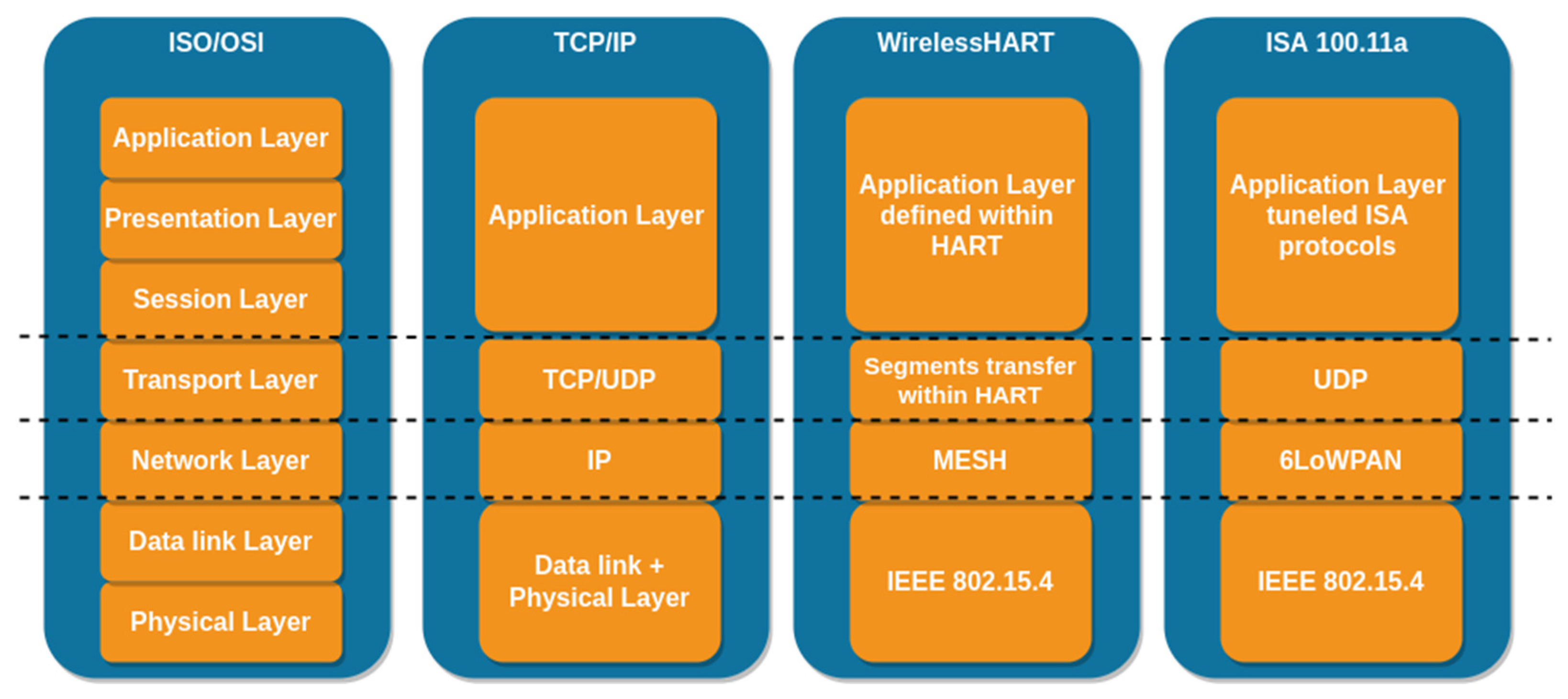
Both WirelessHART and ISA 100.11a are similarly functioning protocols, designed to implement a mesh topology. In this topology, devices within the network can be used to route messages from other devices to their final destination. The WirelessHART protocol performs device addressing at the local level using an 8-byte address (EUI-64) or a 2-byte address (node name). The data transfer and WAN addressing is performed using another communication protocol, the IEEE 802.15.4.
The device addressing and routing within ISA 100.11a communication is handled in a different way, using the 6LoWPAN protocol and the IP protocol in version 6. Therefore, the network layer is based on IETF RFC 4944 (6LoWPAN), which specifies the transmission of IPv6 packets over the IEEE 802.15.4 network, which allows IP connectivity equipment in the field (
Figure 9).
The advantage of the ISA 100.11a standards is that it enables the use of the IPv6 address scheme (128 bits). Usage of this protocol allows the construction of large-scale structures with a large number of devices. However, for physical transmission, both mentioned protocols use the 2.4GHz frequency, Z-wave, and ZigBee (
Figure 9). Therefore, within the framework of stability and security of communication, these protocols share the same level of possible degree of security of communication (encryption of communication, authentication/authorization of individual nodes within the network).
4. Communication Risks of Smart Factory Systems
The Smart Factory production process (and the entire cybernetic system) is formed by a heterogeneous communication structure, where a certain part is implemented using older (bus) communication protocols (Profibus, Profibus PA/DP), and other parts of the Smart Factory communication system are implemented using new protocols, Ethernet industrial protocols, or wireless IoT communication. Each of the systems can also communicate with other production structures and processes (cooperating SF) using a global communication network (Internet).
The emergence of security risks (including the form of security) within the Smart Factory must therefore be divided into at least two groups. These two groups also represent two methods of access to secure communication paths in an industrial environment.
Firstly, bus transmissions and bus data networks. They are specific in that the transmission within such a network is in principle not compatible with the protocols used within WAN networks and thus within the Internet. Due to this “disadvantage”, such networks are physically separated from other communication structures within the enterprise. This physical separation means a substantial “security bonus”, where in principle it is impossible to implement some remote form of attack. The entire infrastructure is owned by an owner, and the level of security is increased by physically preventing access of other persons to the device. However, the disadvantage of such networks is minimal support for data security—there is no possibility of encrypting communication and a minimal possibility of authentication of users and devices. The specificity of these networks is the high resistance of the communication infrastructure against remote attacks and the minimum degree of resistance in case the attack takes place within the local network [
4].
The second group of protocols is more focused on compatibility and transfers within remote systems. There are mainly application protocols, where the actual data transfer takes place using the Internet and the TCP/IP family of protocols (with the exception of some, less-used protocols for data transfer especially in IoT networks, which use their own form of data transfer on the second and third layers of RM OSI). However, it is true that IoT communication is more focused on the transfer of small volumes of data [
48], which is typically the sensing of process parameters with optimization more for the price—energy consumption [
49]. They are generally worse in the field of securing communication; the encryption of communication is energy-efficient and computationally demanding.
The number of types of attacks on information and control systems is considerable; they are implemented at different levels of RM OSI. As is the number of network protection techniques, which is related to the extensive issue of types of attack and defense against them. Generally, attempts to infiltrate a communication network, i.e., “attack”, can be divided into two basic groups. There are passive attacks on the communication network. Their task is to monitor network operations without any modification of transmitted data. The harmfulness consists of the misuse of the data obtained in other activities. Active attacks on the communication network are an attempt to change the transmitted information, posing the possibility of damage to the communication system.
One way to increase security is to focus on the conjugate features of discovered vulnerabilities in the Smart Factory and IoT protocols. A common feature of all mentioned communication protocols is basic vulnerabilities in addressing and data transmission on the Internet. The key element is the TCP/IP protocol. Almost all of the application layer protocols mentioned in the previous section use the TCP/IP protocol for transmission within the third and fourth layers of the RM OSI model and the Ethernet protocol (IEEE 802.3 standard), within the second RM OSI layer. Wireless communication is generally much more vulnerable, but even in this case, it is a transmission using TCP/IP within the third and fourth layers of RM OSI and IEEE 802.15.4 within the first and second layers of RM OSI in most protocols used.
The most known vulnerabilities in the TCP/IP and Ethernet communication stack, according to layers of the RM OSI include:
The given list of possible exploits in the services of the TCP/IP protocols is essentially very brief. In real practice, a number of others are used, based on various combinations of the described vulnerabilities. For example, according to the material available in
Security magazine [
51], 26 different methods have been recorded in practice to implement “Denial of Services” (DOS) and distributed DOS attacks.
The situation is more critical in the case of wireless communication. Because it is not possible to protect the transmission medium, the DOS attacks can be performed quite simply using a signal jammer broadcasting on the given frequency. For example, the LoRaWAN communication protocol is widely used in modern IoT. The work by authors Naidu et al. [
52] discussed the security aspects of the communication of the LoRaWAN protocol.
As a result, several existing security issues have been identified:
The frequencies and channels used are commonly available, so data transmission is extremely difficult to control.
Anyone within the range of the transmitter is able to monitor the communication.
Available devices for the LoRaWAN network do not support any communication encryption.
Packet authorization is not possible (it is not possible to determine in a replay attack whether the commands come from the central control unit or from the attacker).
The problems mentioned can also be identified in other forms of wireless communication, not only in LoRaWAN networks.
5. Protection of Data Transmission in Smart Factory Systems
Protection against several types of attacks on a cyber system can be divided into two main categories. The first category is the physical protection of the transmission system, preventing the physical access of outsiders to the controlled area. Determining how to physically secure access to individual elements belongs to a different field than computer science but preventing physical contact with devices is an equally important aspect.
The second category is a logical form of protection. The method for implementation of logical network protection depends on the place of deployment, and in practice, this can be represented by data encryption, authorization, and authentication of users and systems with a suitable set of passwords and physical elements of active security of communication networks such as communication filtering, e.g., a firewall. Along with the firewall, it is popular to implement into a network many other systems for communication security and attack monitoring. They are systems for attack detection and attack prevention in the communication system, Intrusion Detection System (IDS) and Intrusion Prevention System (IPS), and the Honeypot system [
23]. Probably the most used method of protection is communication filtering using firewalls [
5].
Within modern cybernetic systems, such as IoT networks and Smart Factory production processes, communication takes place primarily between end devices in different layers. Classic firewalls are able to provide the basic level of filtering in the network within the third and fourth layers and are suitable as basic protection, but they are not sufficient to protect this form of data transfer within the Smart Factory or IoT.
The situation is more complicated in the case of using application protocols—an example is the OPC-UA protocol (
Table 1), where communication and transfer of control data take place within the framework of the application, the RM OSI application layer. The solution in this case is to install devices known as application firewalls. In addition to the classic stateful form of filtering, these devices are able to operate on higher RM OSI layers, and thus also on the highest, the application layer. Application firewalls offer a higher level of communication analysis (Deep Packet Inspection). Working within the application layer, such a device compares saved profiles on the normal use of application protocols (data transfer within a specific application on the network) with the actual state, which may indicate malicious activity within the network. If such activity is detected, the firewall may block specific connections to the information system. In practice, they are also known as proxy firewalls (Proxy Gateway), so it is possible to control the content of communication down to the level of commands and data transferred between individual devices. Therefore, the dedicated OPC UA proxy firewall is capable of detecting wrong commands or attempts to violate the security of OPC-UA devices [
53].
The use of proxy firewalls together with stateful firewalls is a commonly used combination to protect communication systems in information networks. In connection with the development of communication within modern industrial enterprises, the application of these devices is very relevant in this area as well.
This method of filtering communication within the cyber system represents the highest level of communication protection. However, the following facts must be included among the disadvantages. First, for each application protocol (service or communication port), it is necessary to create a separate proxy firewall configured exactly for the type of communication expected in the network. Second, it is necessary to remember that such communication control requires some processing time, which results in increased transmission latency. Therefore, this security solution is not suitable for universal application within the Smart Factory.
This problem can be partially solved using a sufficiently powerful system with large computing power. However, such a solution significantly increases the price of the communication infrastructure. In addition to the mentioned ways of implementing filtering within industrial networks, more complex forms of filters are implemented in practice under the name Deep Packet Inspection (DPI) Firewalls. This is due to the fact that the stateful firewall is in principle not able to cover all levels of Smart Factory communication. There exist solutions [
54] that combine a simple stateful firewall together with IDS modules to detect possible attacks. In connection with other systems, it is possible to talk about attack prediction thanks to the use of analytical properties of artificial intelligence [
11], the status packet filter firewall, and IDS.
The combination of the mentioned security devices and technologies into one integrated unit means the creation of a complex solution for the security of industrial systems, e.g., Unified Threat Management (UTM). Such a system aggregates functions such as IDS, IPS, antivirus modules, filtering of transmitted packets (firewall), or the implementation of secure communication channels in the form of VPN and optimization of the use of transmission channels (load balancing). In addition to standard filtering techniques, modern UTM systems also use progressive technologies for the analysis of transmitted data, such as various forms of artificial intelligence [
55]. The communication control mechanism within UTM works on the principle of proxy firewall connection together with data flow inspection on the principle of IDS [
56], as shown on the
Figure 10.
It is clear that a number of solutions and technical means are available to implement in cyber physical systems to increase communication security. However, it is necessary to specify the basic functions of these systems. Institute SANS [
23] has issued the following list of recommended rules (recommended order) for firewalls:
Set filters against spoofing (blocked private addresses, internal addresses appearing from the outside);
Set permission rules for users (e.g., allowing HTTP to a public web server or SMTP to a specific email server);
Set permission rules for device administration and management (e.g., SNMP treatment for network/server management);
Setup the blocking of proprietary, nonstandard, or unused protocols within the Smart Factory internal communication system (blocking OSPF, HSRP, Skype, VTP, etc.);
Set rules for rejection, DENY and warning (notifying system administrator about suspicious data transfer), and ALERT;
Record dropped packets (DENY LOG) for analysis purposes.
According to the mentioned rules and taking into account practical experience in the field of designing cyber systems, available literature sources [
24], and recommendations in the standard of IEC 62443, the generally applicable basic principles of securing cyber systems or Smart Factory can be summarized:
Application of communication filtering in selected places in a suitable form;
Ensuring system inputs;
Deactivation of all processes and functions in the system that are not necessary for the production process;
Deactivation of guest access;
Removal of all unused applications in all systems (stations, servers, PLC, IoT);
Changing all passwords set by the manufacturer and setting the password policy;
Implementation of communication monitoring (IPS);
Installation of antivirus protection for workstations and servers;
Favoring the use of encrypted communication with sufficient key width, if possible;
Minimization of communication inputs to the industrial zone (and below) from external systems (only trusted and verified entities).
In addition to the above list, the following rules can be useful:
All high-critical and medium-critical production systems, whose communication to the outside (to other parts/zones) is necessary, must be secured using a corresponding firewall located at the border of the zone;
All high-critical and medium-critical production systems that only communicate with devices within one zone must be isolated from the external network (from the Internet and other systems);
The management of high- and medium-critical production systems (configuration, structure modification, backup, update, etc.) has priority within the cyber system;
All firewall security policies and rules within zones must be consistent with the overall defined security policy within the Smart Factory;
All security elements and devices within the network must be monitored centrally and backed up according to the backup plan, including all documentation.
6. The Proposal of Cybernetic System Security
In this section, first, the defined rules for the segmentation of the production system [
4] are presented, and then the steps to achieve a secure cybernetic system are presented. In the end, an experimental example of cybernetic system security is presented. The problem area is large in scope, and the proposals are based on the previous text and the literature sources.
The rules defined in the proposal are in accordance with the procedures and rules specified in the mentioned standards (especially the mentioned IEC 62443), and the methodology is also presented in accordance with the Defense-In-Depth strategy [
58] and contains requirements for both horizontal and vertical segmentation of the enterprise architecture.
The security process can be divided into two steps. The first phase is the identification of entities, risks, the impact of risks on the functionality of critical systems, and the separation of the entire cyber system into homogeneous zones from the point of view of the established level. The second phase consists of a more detailed analysis of each zone, determining the required level of security for individual parts, and defining procedures to achieve the required level.
For the first phase, the segmentation of the entire infrastructure into individual separate logical areas (zones) appears to be a suitable solution. Industrial process zoning is well known [
4] (
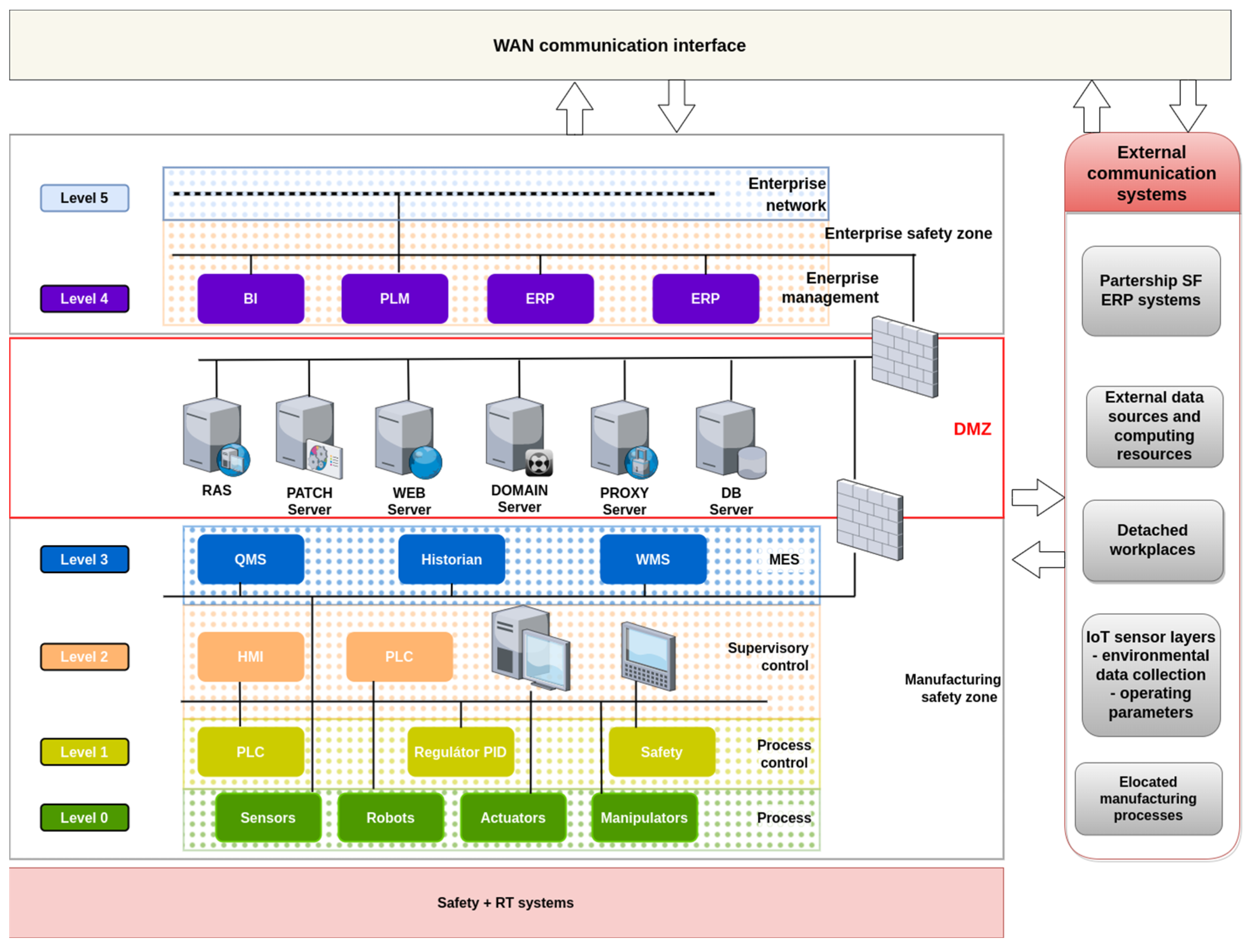
Figure 13).
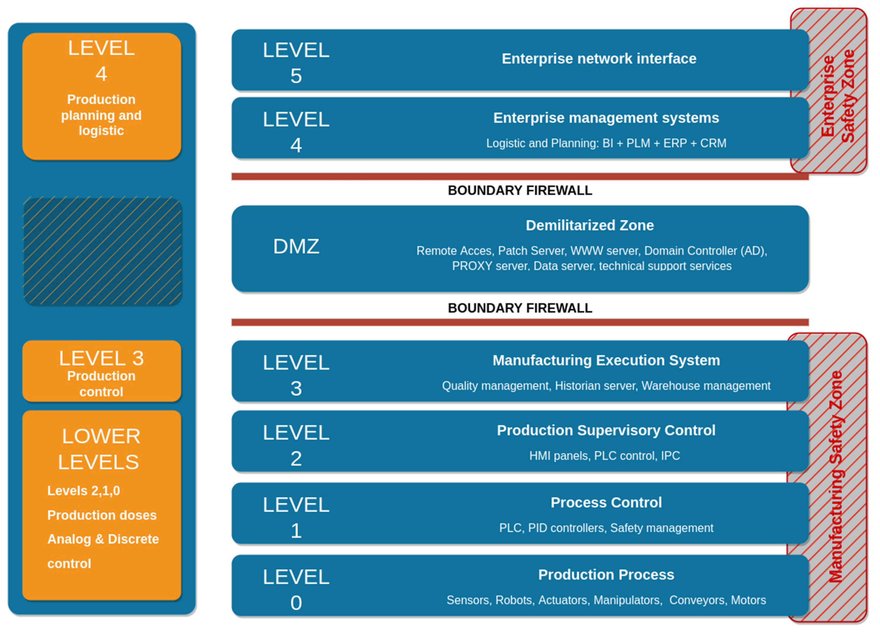
The entire system can be divided according to the Purdue Enterprise Reference Architecture (PERA, ISA-99) [
57], where the manufacturing process is divided into three zones and six logical levels:
Enterprise zone;
Level 5: Enterprise network interface;
Level 4: Logistic and planning (BI + ERP);
Industry Demilitarized zone (DMZ);
Manufacturing zone;
Level 3: MES, manufacturing control;
Level 2: Production supervisory control;
Level 1: Process control;
Level 0: Process.
The lower levels of architecture (levels 3, 2, 1, and 0) are usually time-dependent processes, and thus their separation of the external network in the form of a demilitarized zone appears to be necessary.
The situation can be different in the environment of modern Smart Factories. The objects at the lowest level communicate not only with each other but also transmit information within the higher layers of the corporate structure or directly to the Internet.
The solution is to divide the lower layers into groups of devices according to the degree of possible risk into classes and vertical segmentation of horizontal lines. This gives us a breakdown of the safety of the entire production process according to the functionality of the individual components. This form of division in the production process is the basis of the IEC 62443 standard, and this method of securing industrial networks is also well applicable within the Smart Factory.
For the first phase, the following implementation steps can be proposed:
Identification of all entities and objects entering into communication within the Smart Factory and the entire cyber system.
Dividing the system into individual zones and defining the communication policy between the created zones. It is necessary to create separate zones for:
IoT devices;
Separate zone for IT networks and production networks;
Zone for SCADA;
Separate MES zone;
Separate demilitarized zone;
Separation of communication channels towards other Smart Factories and external systems (I/O interface to the Internet, cloud services, report services, external ERP, etc.).
The division of zones into individual subzones based on the relevance of the type of data transfer and the type of equipment:
Separation of subsystems with temporary connection;
Separation of parts according to the communication protocols used;
Separation by location/location of systems;
Creation of sub-zones according to the physical form of transmission within the RM OSI physical layer (department of wireless communication);
Separation of subsystems with remote connection;
Creation of sub-zones for safety elements.
Determination of the level of risk for individual subsystems, zones, and subzones according to the standard ICE62443, part 3−2) taking into account critical systems according to IEC 62443-3-3.
Identification of zones and subzones and determination of rules for individual zones and subzones so that the minimum requirements for system security are met:
Unique identification of each zone;
Defining zone boundaries (logical/physical);
Determining the interface for communication between zones and defining communication flows (inputs and outputs) to each zone (firewalls within the transition between zones, transparent firewalls);
Elaborate a list of all devices and processes that are part of the zone;
Developing an identification (list) of all processes and zones dependent on the zone;
Set the assumed security level of all zones.
Development of procedures to achieve the required level of security within the system (in zones, subzones, establishment of border policy):
Defining the method of authentication, authorization, and identification of objects within the zone;
Defining the physical security rules of the production system;
Defining the logical security rules of the production system;
Creation of interfaces for communication between zones;
Defining communication flows (inputs and outputs) to each zone (set the firewalls within the transition between zones—transparent firewalls).
Defining the method of maintaining the status of the achieved level of security:
Setting up monitoring of activities and events within individual zones (IPS, log analysis);
Determining the update method (WSUS server) and setting rules for individual objects (zones, subzones, devices);
Defining the archiving of objects within individual zones (backup server, backup management).
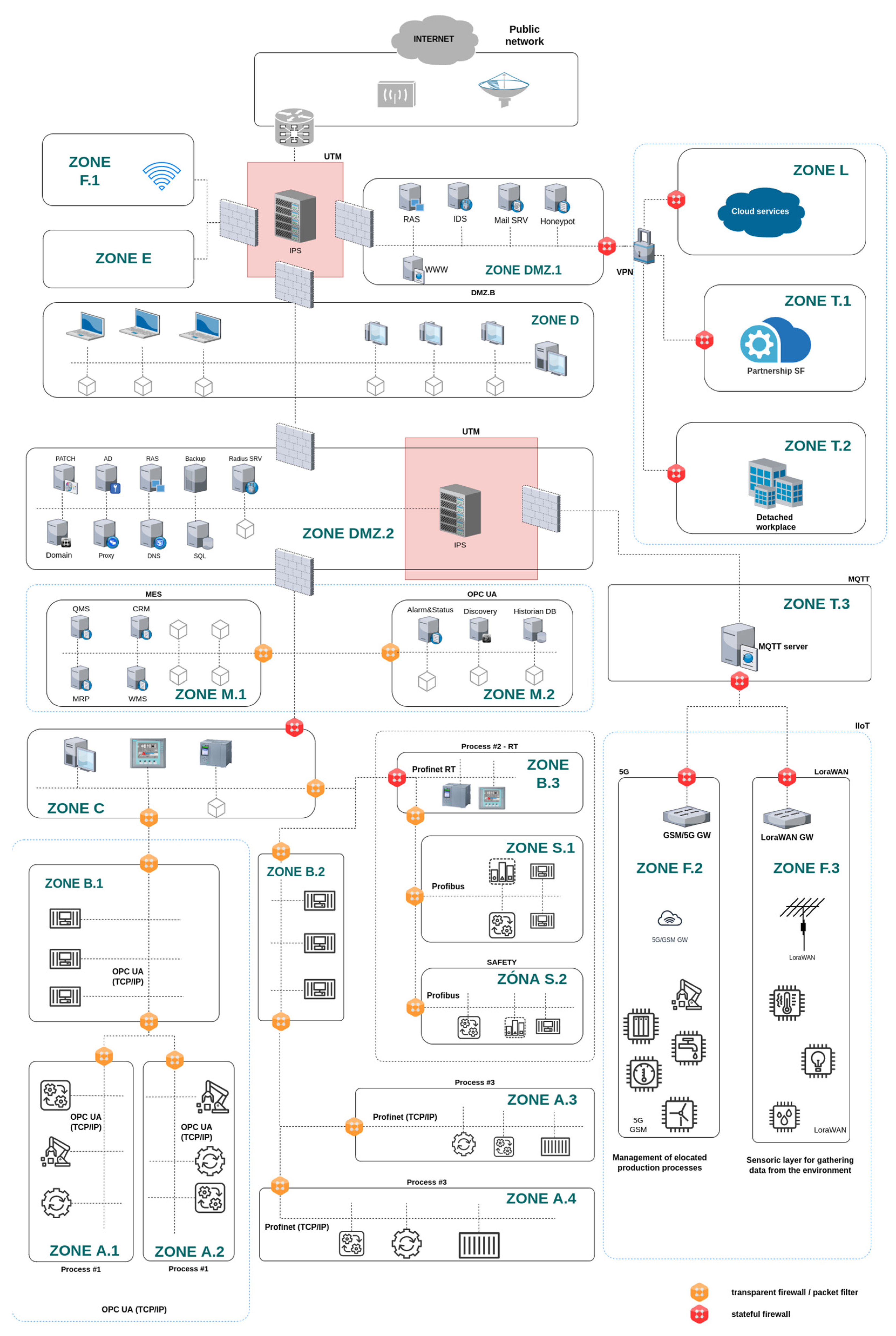
The proposed production process model is represented schematically in
Figure 14. The model is designed in accordance with the layered architecture of industrial systems in an open communication environment, and the entire production process is divided into layers corresponding to individual operations defined within these layers. In principle, it is based on the model according to Ackerman [
4] (
Figure 13).
The entire scheme proposal (
Figure 14) is extended using a safety level zone—time-critical processes and RT communication. The reason is that systems based on communication using wire technology, built on classic protocols suitable for system management, are still part of modern enterprises. The communication security of these networks has certain specific properties, and compatibility with Ethernet technologies is debatable. For such parts of the Smart Factory, it is appropriate to establish a separate zone. This approach is also recommended in the ISA/IEC 62443 standard and is in line with the CPwE concept [
59].
The first point of the proposed procedure is the identification of devices, i.e., a precise description of all devices within the cyber system (Smart Factory).
For evidence of all devices, it can be suggested to use the existing equipment and material registration system, if it is possible due to many recorded parameters. Each device in the network needs to be registered in such a way that it can be exactly identified in the network. This includes location data and is consistent with the creation of zones within complex systems.
Based on the literature sources [
6] and personal experience, the following data are suggested for satisfactory identification:
Device identification (identification code, number, or name);
Device description (router, server, PLC, HMI, tablet, phone, etc.);
Manufacturer and model;
Operating system version and firmware version;
Communication protocols and services running on the device, including their version;
Physical location of the device;
Physical address of the device (MAC address);
Logical address of the device (in the case of IP networks it is the IP address/mask);
Open communication ports;
Access rights;
Implementation form (physical device / virtualized);
Other (device fingerprint, age, time since launch, physical version of the device, etc.).
In addition to physical devices, every cybernetic system /Smart Factory also includes several pieces of software equipment. The software is running not only on computer stations and servers but can be also represented as an application running in HMI, PLC, robots, etc., and must be recorded.
For each installed application, we suggest recording at least the following parameters:
Application name (identification);
Application version;
Allowed users (number and level of access);
Dependencies and communication tunnels within the network (data flow within the application);
Application licensing method (temporary, online, token, open source, etc.);
Date of the last update;
Necessary hardware equipment;
Other (CRC, App-ID, etc.).
The next step after the identification of all objects in the system is important, which is the phase of division of the entire structure into zones. The zone division process is based on many factors—the communication flows, processes performed within the function of the individual elements, the given security policy, etc. In a simplified case, the structure of the enterprise in the form of levels (
Figure 14) can be used as a draft and adapted to zones. This helps to create the basic structure and ensure the horizontal zoning of the cyber system. The next step after the identification of all objects in the system is important, which is the phase of division of the entire structure into zones. The zone division process is based on many factors—the communication flows, processes performed within the function of the individual elements, the given security policy, etc. In a simplified case, the structure of the enterprise in the form of levels (
Figure 12) can be used as a draft and adapted to zones. This helps to create the basic structure and ensure the horizontal zoning of the cyber system.
6.1. Level 0—Process
Level 0 contains a spectrum of elements such as sensors, power elements, manipulators, motors, motor drivers, and so on. The specificity of these devices is the form of communication (often deterministic) and the volume of transmitted data (small volumes of data). They are bound by the environment, and their placement within the production process adapts to the physical process. These are usually a number of devices with varying degrees of communication capability within the network (according to services specified in RM OSI). This is where the impact of IoT implementation in an industrial environment in conjunction with smart sensors is most evident. While classic sensors communicate with control elements in a higher layer, in the form of proprietary protocols, modern sensors support a range of communication protocols designed for the IoT. Another specificity is the possibility of updating—simpler devices within this layer often do not require this form of maintenance throughout their lifetime; functionally more complex “smart” elements are the opposite case. According to the proposed methodology, it is necessary to divide the horizontal zone into subzones according to these criteria and at the same time establish specific communication rules for specific sub-zones. The basic designation of this level will be ZONE A with the designation of subzones ZONE A.x, where x = 1...n. IoT devices will have the basic designation ZONE T, analogously subzones ZONE T.x (x = 1...n). The functionality of elements and devices and the communication between them within this layer is critical to the security of the manufacturing process.
6.2. Level 1—Process Control
The classic architecture of the production process mainly belongs to this layer of logic controllers—PLCs, which ensure the production process through direct communication with sensors and executive members. In the case of a Smart Factory, within this layer, the production process is realized using software elements and a program within the software equipment of IoT devices. Production and control processes are primarily dependent on communication between autonomous elements. The IoT parts are subject to similar conditions as the IoT devices under Level 0 (essentially the same elements). The communication of IoT devices takes place primarily within this level between individual devices. Fewer data flow towards higher levels. The control and supervision of the PLC are mostly dependent on the decisions of the higher layer objects—HMI and IPC. The designation of zones is within the design: ZONE B, analogously subzones ZONE B.x (x = 1...n). The functionality of elements and devices and the communication between them within this layer is equally critical to the security of the manufacturing process.
6.3. Level 2—Production Supervisory Control
A typical representative within this zone is operator interfaces—HMI panels and various control and monitoring systems represented in the form of IPC or workstations. The communication model is mostly dependent on the Ethernet protocol and the TCP/IP protocols. The devices can provide all services within the RM OSI layers. The designation of zones is within the design: ZONE C, analogously subzones ZONE C.x (x = 1...n). Even in this case, ensuring communication within this layer is critical for ensuring the production process.
6.4. Level 3—MES Services
This level is the highest in the hierarchy of production management and at the same time is the last level within the entire model whose functionality elements and communication are critical to the production process. Within this layer, the objects are primarily workstations and servers. Production management is implemented with MES, and services for ensuring the production process are a spectrum of services provided by various servers necessary for MES and the overall functionality of the cyber system/Smart Factory. The following server solutions and network services can be included in this layer: historian server, file server, DNS, WINS, NTP server, WSUS server, backup server, terminal server/RAS, domain server, DHCP server, active directory server, reporting server, MAIL server, WWW server, and more. Considering the number of services that can be included in this level, it is appropriate to split the layer into two: the MES layer (ZONE M, with subzones analogous ZONE M.x (x = 1...n)) and the new zone for other network services—DMZ (demilitarized zone), with labels DMZ.x, (x = 1...n). A good reason for such a division is the difference in the way of communication (the kind of communication protocols and services used) towards the lower layers, i.e., the production process and to the higher layers. MES systems provide support directly for production process equipment; other systems provide data services within the communication network for all layers (DHCP addressing, updates, backup, etc.).
6.5. Level 4—Enterprise Management Level (BI + ERP)
This layer consists primarily of computers and workstations with appropriate software used for management on the highest enterprise level (ERP + BI). Devices in this layer must have secure access to services and devices within the zones “DMZ.x” and “ZONE M.x”. In addition, the “Level 4” devices connect to external systems and cloud services in the Internet environment. The functionality of these devices is not considered critical for the production process (48). The data transfer is typically (about 90%) towards the Internet, commonly with the TCP/IP protocol. The designation of zones is within the design: ZONE D, with subzones similar to ZONE D.x (x = 1...n).
6.6. Level 5—Enterprise IT infrastructure
This layer includes devices that do not have a direct impact on the production process and do not directly read data from the production process. As an example, the B2B and B2C interfaces can be assigned to this level. The functionality of the devices within this layer does not affect the safety and function of the production process. The separation of devices (layers) from the Internet is an important element in any case. The designation of zones is within the design: ZONE E, with subzones similarly ZONE E.x (x = 1...n).
In addition to the above horizontal zones division of the production process and subzones definition is the creation of a special zone. The ‘Safety’ and ‘RT’ processes are special. It is necessary to create a specific communication environment within the entire cyber system. These devices must be separated from the entire communication infrastructure but with the possibility of data transfer and information to higher levels of the cyber system. The designation of zones is within the design: ZONE S, with subzones similar to ZONE S.x (x = 1...n).
Wireless communication deserves a special approach too, mainly IoT communication and IoT devices within the production process. All wireless connections must always be separated by a standalone zone according to process architecture in the form of a subzone within the main structure of the production process or by creating a separate zone connected to the DMZ. In this case, the designation of the wireless communication section will be ZONE F, with analogously subzones ZONE F.x (x = 1...n).
The last two types of zones in the design are made up of devices with a remote connection to the system. They are the following: ZONE T and a zone for cloud services, ZONE L. The subzones are analogously named ZONE T.x (x = 1...n) and ZONE L.X (x = 1...n).
The next stage is determining the level of risk for individual subsystems, zones, and subzones in accordance with the ICE62443 standard part 3-2, with regard to critical systems in accordance with the IEC 62443 part 3-3. This process includes establishing the basic requirements for the system (Fundamental Requirements) and, subsequently, setting the security level for zones and systems (SL2, SL3, SL4). The definition process depends on the actual conditions and the environment in which the security is implemented. If there is a situation where within the zone there are devices that achieve a different level of security, then the entire zone must be adapted to the device from the lowest level of security achieved, or new subzone can be created. The level of sub-zone security can be improved in different ways (adding communication rules, unifying protocols, strengthening the degree of security of operating systems—OS hardening, etc.).
After the process of zone and subzone creation is the next stage, the process of setting the security policy and transition policy at the borders of individual zones and subzones.
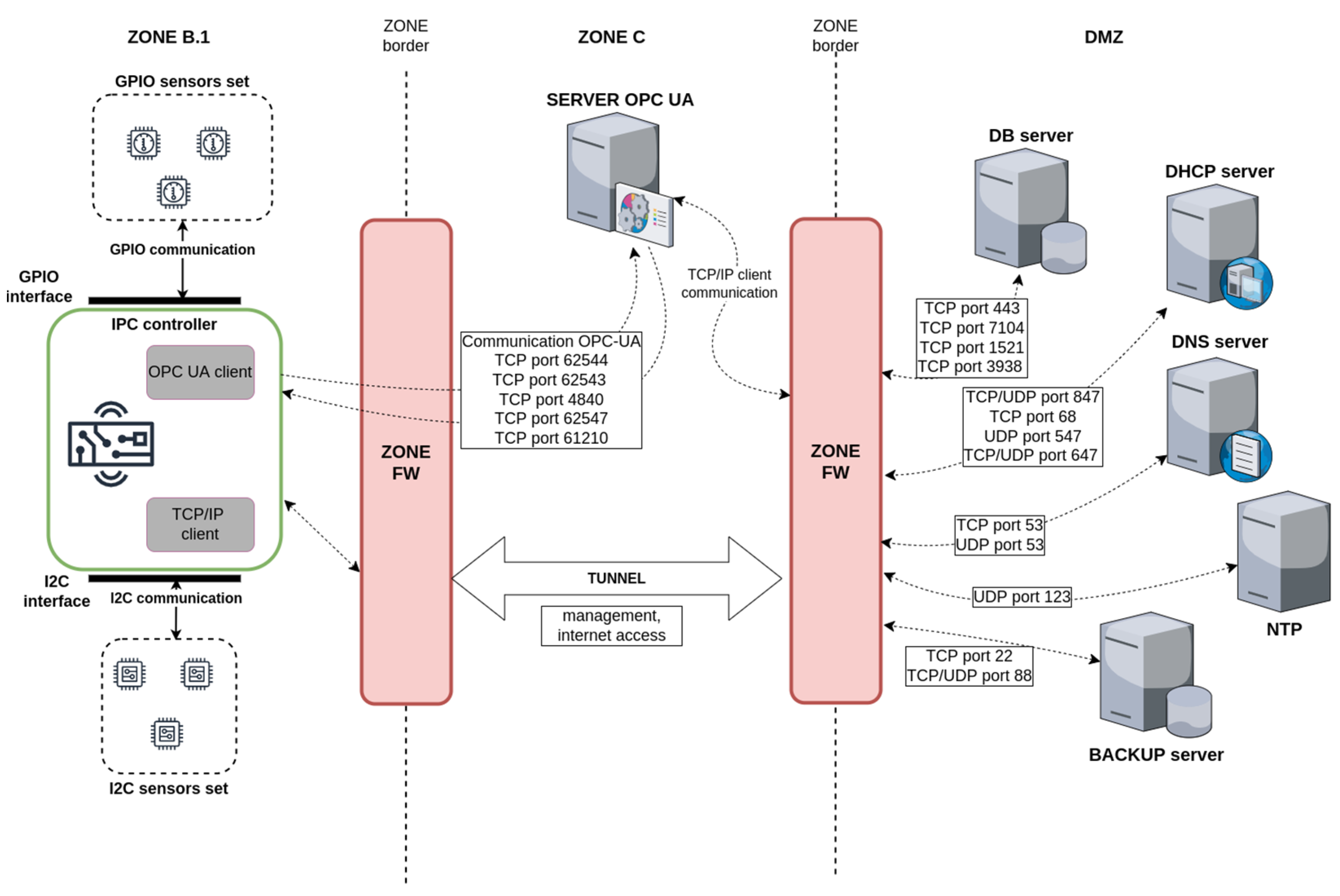
The process of creating security filters between zones within an industrial network is an essential element in securing cyber systems. For successful implementation, it is necessary to know in detail all the communication flows within the running applications for the identified devices and processes. Based on this knowledge, it is possible to create communication interfaces (filters) between individual zones and subzones. The example of communication transfers and common TCP/UDP ports used in OPC-UA communication is shown in
Figure 15.
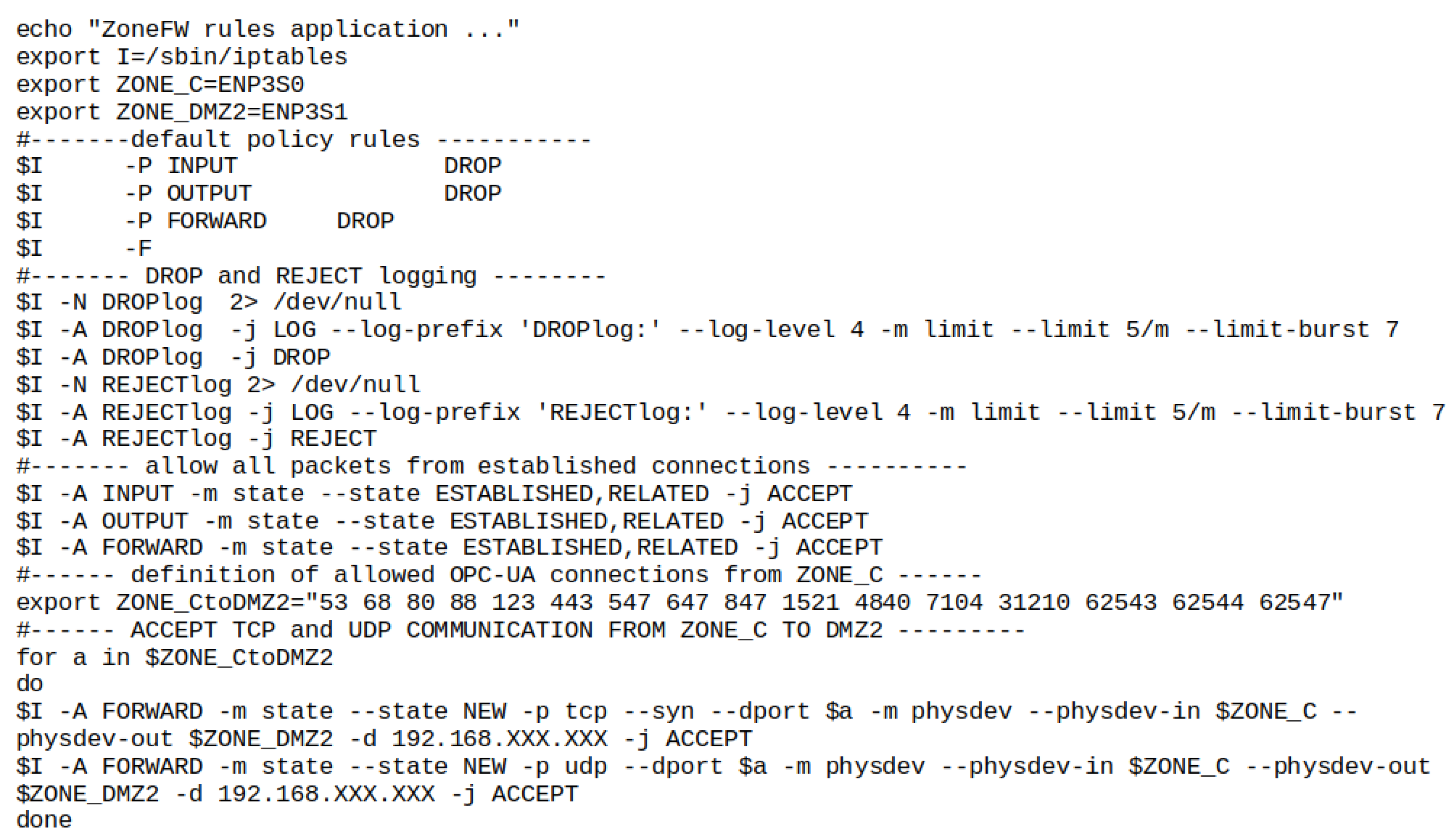
In order to achieve the required level of security, some form of communication control must be applied at the border of each zone. The device ‘Zone Firewall’ can be a different type according to the degree of communication complexity in the system and desired security level. For simple (and fast) communication models, a packet filter is probably sufficient, but in the case of more complex systems, it is necessary to apply stateful firewalls or transparent firewalls. A brief example of the script for creating a stateful firewall for an OPC-UA zone (stateful FW between ZONE C and ZONE DMZ2) is shown in
Figure 16.
To create a simple communication filter on the border between zones, it is possible to use L3 or L2 switches for the connection of individual zones. The functionality of these network devices is suitable for the creation of a simple data communication filter. To implement a higher level of filtering, i.e., a stateful firewall, computing systems based on Linux OS are often used in practice. The advantage of this operating system is the simple implementation of rules directly in the kernel. The mentioned system property is available in the ‘iptables’ command. It is used to set up, maintain, and inspect the tables of IP packet filter rules in the Linux kernel.
The highest level of security is the application firewall, more suitable for higher layers within the cyber factory structure. Their advantage is maximizing the level of communication security, but they are not suitable for use in zones with direct low-level communication between devices and the process layer, due to increased transmission latency and perhaps unnecessarily complex equipment.
A proposal for a possible implementation of a cyber system security methodology is shown in
Figure 17. The design uses the principle of zonal security in a Smart Factory environment and is designed in compliance with the recommended implementation rules.
The division of the system into zones is the key element for the security of the entire system. The solution is the implementation of communication gateways for the control of communication within zones and between individual zones. Two types of such devices are used primarily in the proposed solution. In general, a lower level of security is achieved using simple packet filters (orange color).
The network packet filter provides an adequate level of security, and the control of communication does not cause an increase in the transmission latency within the lower layers when controlling the processes in the system at the RT process level. A higher level of security can be set using stateful firewalls (red color). They provide a higher level of security; however, due to the data processing process, they introduce a time delay in communication. Choosing the right type of gate is specific to the particular device and situation.
An important element in the proposal is the separation of wireless parts of the cyber system (ZONE F.1, ZONE F.2, ZONE F.3) from key areas using the UTM system and demilitarized zones (DMZ.1 and DMZ.2), while individual subsystems are separated from each other using stateful firewalls. The premise of such a solution is that critical time-dependent operations will not be controlled within the IoT.
A special situation within the technological layer is found in the area of the interface between classic protocols and devices (ZONE S.1 and ZONE S.2) with the superior layer for process control (ZONE B.3), where a higher level of security is applied precisely at the interface to MES (ZONE C). This solution is applied due to the lower security option (authentication + authentication), and thus the higher level of vulnerability, of devices within the classical automation part.
The highest security level in the form of a UTM firewall is implemented within the proposal framework at the interface of higher layers and the MES layer. The reason is the need to create a border between cyber system zones that are critical for the production process from higher layers and from interfaces between the Smart Factory and external communication structures (Internet, allocated operations, and the like, etc.).
The specific setting of communication gateways (FW rules) depends primarily on the protocols and services used within the individual parts of the Smart Factory. In real practice, this is a very complex activity, practically unlimited in time during the existence of the production process.
Together with setting the communication rules and layer separation, defining the policy for updating network software components and setting a data and application backup is necessary. Updates to software components are essential to eliminate problems and security threats in cyber systems. Here is the obvious difference between classic automation systems and modern Smart Factories. While in the case of classic automation systems, the software is updated minimally (mostly only when the production process is modified), in the second case, in SF and IoT systems, updating the firmware of devices is a normal work operation. By applying new firmware, it is often possible to increase the functionality and efficiency of the devices and remove existing vulnerabilities that were not known at the time the device was implemented in the system.
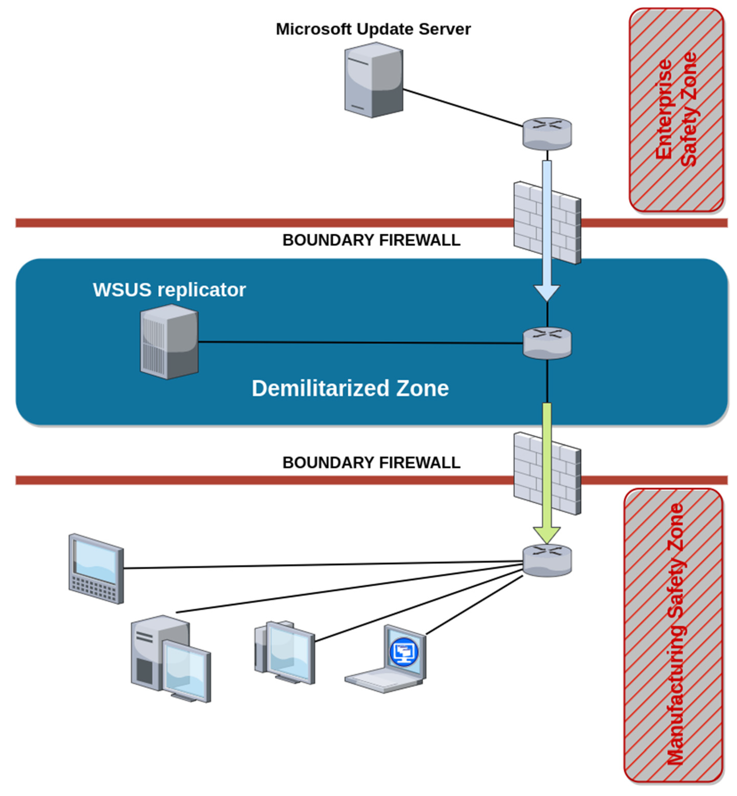
In addition, the update may remove existing software bugs. Because the entire Smart Factory cyber system is a composition of servers and workstations together with elements of industrial automation and IoT intelligent (autonomous) devices, the upgrade process within the enterprise must be adapted to individual zones. For workstation and server operating systems, updates are mostly available as a manufacturer’s service. In the Windows workstation environment, this includes the use of the WSUS replication server in an efficient way (
Figure 18).
For other operating systems, the situation is similar, and updates are available directly for the specific operating system. Other hardware elements and components that are part of the Smart Factory need to be handled individually. The software versions and updates must be part of the software records within Smart Factory. The implementation of a central server with an updated database within the DMZ zone is strongly recommended.
It is also important to define the form of update for individual devices (periodic, automatic, systematic) and to set the plan for the update of critical parts of the production process. This area requires a specific approach (testing dependencies, functionality, system restart plan, etc.).
Within the area of Smart Factory and cyber security, a backup policy must be established, and the objects intended for backup must be defined. Each incident can cause two levels of damage to the systems. A lower level of damage is when it is possible to implement a correction to the original state simply by restarting the affected elements or parts of the cyber system. Higher levels of damage include physical damage to system elements and data. Data backup within the Smart Factory is especially important in the second case. According to our own experience and other sources in the literature [
6], a backup policy must be established, and the objects intended for backup must be defined:
Disk images of workstations and servers;
Configuration files and important databases (accesses, user accounts, alarm ranges, etc.);
Programs and data of all PLCs (source programs);
Configuration parameters and firmware of intelligent sensors and controllers;
Historical records of SCADA systems (historian server);
Firmware of IoT and PLC devices;
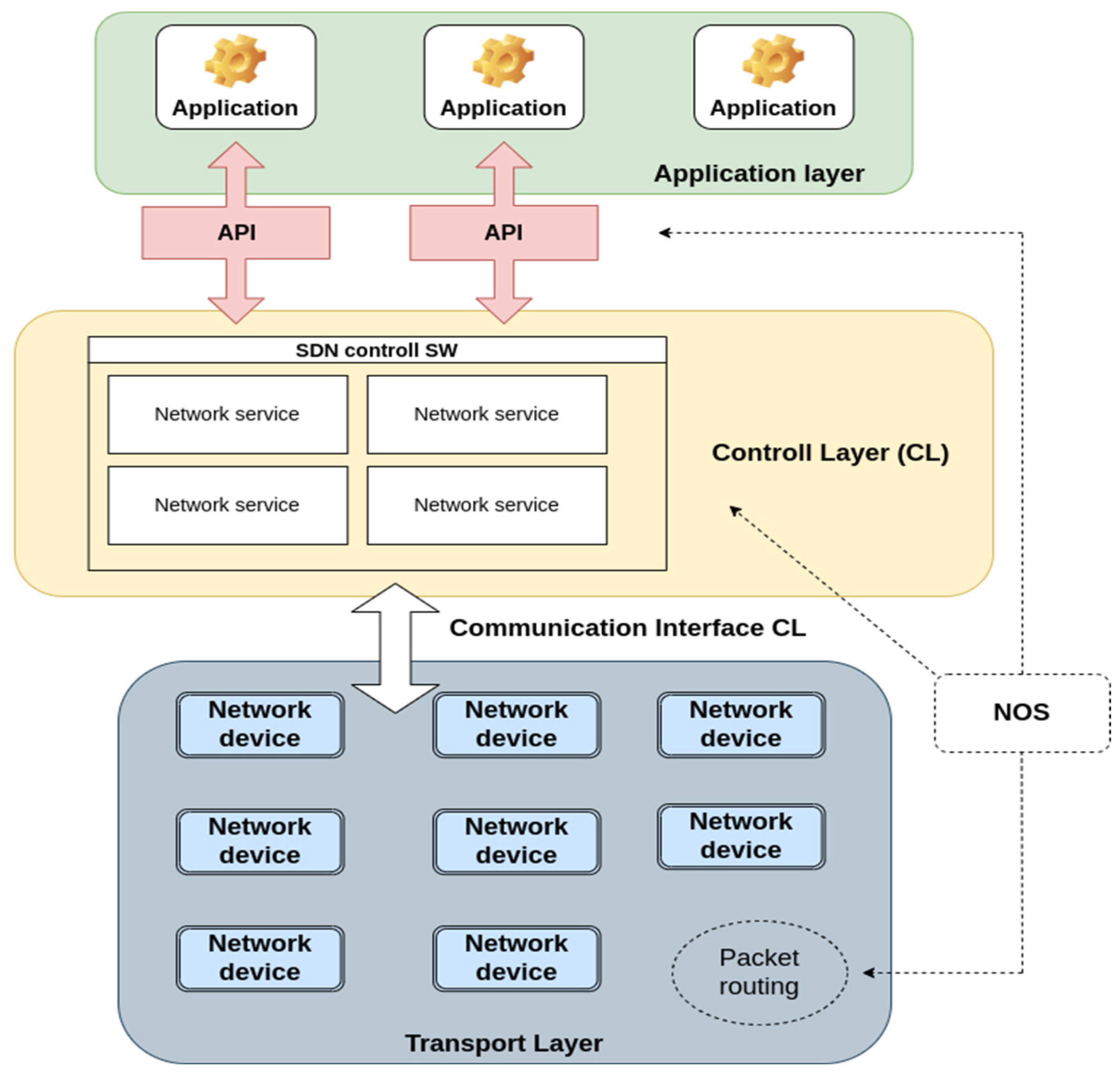
Configuration scripts of key elements of the communication network (routers, switches, VPN servers, firewalls, SDN controllers, etc.).
It is necessary to define the entire backup process: establish the periodicity of archiving, the method of implementation for individual systems (automatic, manual, periodic), the form of data storage and the length of storage of individual archives, and the method of securing sensitive data against misuse. Finally, the backup politics has to respect the 3-2-1 rule, which represents:
First, 3 backups—storage of at least three archives in a chronological sequence;
Second, 2 forms/methods of implementing the archive—storing archives from one time stamp in two different technologies;
Third, 1 version of the archived data is always outside the location of the archived device.
7. Conclusions
The field of cyber systems communication security is very complex due to the number of devices, transmission forms, and the variety of technological solutions in the spectrum of industrial applications. In general, this work summarizes the issue of communication security in the modern production environment.
In the first part of this work, the focus is on the analysis of the most frequently used protocols in the Smart Factory industrial environment. There is a created list of protocols used within the Smart Factory, and they are assigned to individual RM OSI layers to identify common properties. The output is the statement that the overwhelming majority of wired and wireless forms of communication of industrial systems are dependent on the TCP/IP communication protocol. In addition to the TCP/IP communication stack, wired communication of the most widely used protocols also uses the Ethernet protocol within the second layer of the RM OS.
From the aforementioned finding, it is clear that all known protocol-dependent vulnerabilities in the field of IT communication systems are directly applicable to modern industrial enterprises. In connection with the expansion of the use of IoT technologies, the situation is particularly critical in the case of wireless communication. Using the principle of function, wireless networks do not allow the prevention of unauthorized access to the transmission medium. Several wireless technologies use their own way to deliver link frames for transmission within the data link layer. However, these are proprietary solutions with a lot of room for a potential attacker.
The outcome is the fact that industrial systems are more vulnerable than information systems, and it is necessary to use active security means (firewall, IDS, IPS, Honey Pot) to protect them, even to a greater extent than in ordinary IT. The reason is that many new standards are used in automation, the infrastructure of modern facilities is considerably heterogeneous, the frequency of updates is minimal or none, and potential damages and risks are significant.
The main contribution of this article is the proposal of a new approach to making a modern production system using a form of process and systems separation with security elements. The methodology is presented in the form of simple and clear rules, and the rules are styled as a list.
This proposal is notable because it creates separate zones for each system within the production process, similar to sandboxing of applications within computing systems. A key element is the implementation of specialized firewall technology to establish strict rules for the flow of communication between zones. The advantage of the proposed architecture is the fact that with such an architecture it is practically impossible to infect the communication paths of the entire production process—every part of the production system is isolated from the other parts and the communication is strictly defined using firewalls, and special focus is given to the separation of wireless communication and external systems.
For many types of firewalls, the use of two technologies is suggested. In lower layers of the industrial communication system, it is convenient to use simple and fast packet filters because of the processing delay and the RT communication request. At the border between zones without RT communication, the use of a more sophisticated form of data processing, i.e., a stateful firewall, is suggested. The greatest attention should be paid to the interface between the IT network and industrial systems. A suitable solution is to install the UTM system, including IDS, IPS, and antivirus systems. The same approach can be suggested to the external workplaces department, partnership Smart Factory, parts of the production process with wireless communication, and IoT, respectively.
One part of this work is the proposal of a generally applicable set of rules, the ap-plication of which makes it possible to implement a communication-safe production system in the Internet environment. The given list of rules reflects the recommendations in existing norms and standards in the field of cyber systems security, together with the principles recommended in a number of related professional literature, including knowledge and comments based on personal experience gained from many years of experience in the field of IT communication and industrial systems. It is obvious that similar rules are set in all communication systems to achieve a higher level of security, but the list is adapted for application in the Smart Factory area.
A general example of the application of the proposed methodology is given in the final part of this article. Within the proposal, the work presents a model example of the separation of objects within the Smart Factory, together with an example of creating a communication filter (stateful firewall and DMZ zones) in an OPC-UA environment using Linux iptables configuration script. Everything is summarized in a given scheme, together with a detailed description of the implementation of the rules for individual zones in the cyber system. Although it is implemented on a theoretical level, it is applicable within the spectrum of real solutions in production practice and gives a usable example of the production process separation in the Smart Factory. In conclusion, all of the outputs (i.e., the methodology proposal and security rules) reflect the existing literature sources and standards.
The truth is that the problem area treated in this work is subject to rapid development, and the specific validity of the mentioned rules is time-limited by the development of new and the existence of current communication standards in cybernetic networks. Nevertheless, the conceptualized methodological rules are currently up-to-date and, in a general form, can be reliably used in the future.
