Article

Temperature Rise Calculation of the High Speed Magnetic Suspension Motor Based on Bidirectional Electromagnetic–Thermal–Fluid Coupling Analysis

School of Mechanical, Electrical & Information Engineering, Shandong University, Weihai 264200, China
*
Author to whom correspondence should be addressed.
Machines 2023, 11(3), 364; https://doi.org/10.3390/machines11030364
Submission received: 11 February 2023 / Revised: 3 March 2023 / Accepted: 6 March 2023 / Published: 7 March 2023
(This article belongs to the Special Issue Electrical Machines and Drives: Modeling, Simulation and Testing)

Abstract

:
In order to accurately analyze the temperature distribution of a high-speed magnetic suspension amorphous motor, a multi-physical coupling method, including flow field, electromagnetic field and temperature field, is proposed. The electromagnetic loss obtained by electromagnetic analysis is directly mapped to the temperature field and input to the boundary conditions of the flow field for several coupled iterations. This paper compares the thermal analysis results of two different temperature rise calculation methods, analyzes the temperature distribution of magnetic suspension amorphous motor under different working conditions, and discusses the simulation results and the measured results. The error between the multi-field coupling simulation results and the experimental results is less than 10 °C, and the error of the traditional temperature rise analysis method is 30 °C, which verifies the superiority of the proposed coupling analysis method in improving the calculation accuracy of motor temperature rise, and has important significance for the accurate prediction of motor temperature rise in the design stage.

1. Introduction

Magnetic suspension amorphous motor (MSAM) adopts magnetic suspension bearing-less technology to avoid mechanical friction loss between traditional mechanical bearings and the rotor, reduce heat, and further improve efficiency. Therefore, it is widely used in high-speed centrifuges, flywheel energy storage, and other important facilities and equipment, and it also has a good application prospect in the aerospace field [1]. However, because of its high power density and small heat dissipation area, the heat dissipation of the motor is a very serious challenge. Especially for the MSAM, the rotor is not in contact with the rest of the machine. If there is no cooling convection, the heat generated by eddy current loss will accumulate in the rotor, causing irreversible demagnetization, affecting the torque and performance of the motor, and leading to unstable operation of the motor [2,3,4,5]. Therefore, the effective heat dissipation of the MSAM is very important. An accurate evaluation of loss and its distribution is the basis of accurate analysis of temperature rise, which requires a more accurate temperature rise calculation method in the motor design stage, so as to adopt appropriate methods to cool the motor heat dissipation.
Relevant scholars at home and abroad have fully studied the solution method of the motor temperature field and accumulated valuable reference experience. At present, the calculation methods of motor temperature field mainly include the traditional empirical formula (TEM), lumped parameter thermal network (LPTN), finite element method (FEM), electromagnetic-thermal-fluid coupling (ETFC). The LPTN method is used to approximate the temperature field of the motor. The field is divided into several unit nodes. Based on the thermal resistance and temperature rise transfer in Fourier heat conduction law, the temperature field distribution of the motor is calculated by adopting a principle similar to Ohm’s law [6]. However, if the precision of the motor temperature field is required to be high, the number of nodes and thermal resistance in the small network must be greatly increased by adopting the equivalent network rule, which greatly increases the workload of the motor temperature rise [7,8]. On this basis, some scholars use finite element software to divide the solution domain of the motor into several small units, forming a discrete solution model. By applying certain boundary conditions and parameters, the temperature distribution of each part of the motor is obtained [9,10]. The biggest limitation is that the software uses an empirical algorithm to calculate the convective boundary, and the accuracy needs to be improved [11]. Some scholars also use the method of loading uniform loss density to combine the electromagnetic field and temperature field to analyze the temperature field of the motor [12]. However, in fact, motor thermal analysis is a reflection of the interaction of the electromagnetic field, temperature field and fluid field, and cannot be simply superimposed. Because the rise in temperature has a certain influence on material characteristics, the loss distribution, and flow field conditions, electromagnetic (EM) loss determines the heat source of the temperature field [13,14,15]. Therefore, for the electromagnetic heating phenomenon under high-speed operation of the MSAM, it is not suitable for the single FEM analysis, nor is it suitable for the TEM. In order to obtain accurate temperature field results, multi-physical field coupling analysis must be carried out. In [16], a multi-physical field simulation method based on an ETFC iterative solution is proposed. The EM model is established to solve the electromagnetic loss, and the interaction effect between the motors is considered. The convection conditions are simulated by computational fluid dynamics (CFD) software. However, the effect of temperature on the properties of magnets has not been fully discussed. Therefore, in order to obtain accurate temperature field analysis results, it is necessary to fully investigate the influence of temperature on the electromagnetic properties of motor materials, and combine multi-physical field coupling analysis to improve the analysis accuracy.
In this paper, the loss and temperature rise characteristics of a MSAM are studied in detail. The EM method is used to consider the influence of temperature on the electromagnetic characteristics of magnets in detail, and the iron loss, copper loss, and eddy current loss of magnets are analyzed. At the same time, combined with the CFD analysis of the flow field, the influence of the motor speed on the cooling air speed and the air friction loss is analyzed. Based on the ANSYS platform, the data transfer is realized, which not only considers the non-uniformity of the loss distribution of each part in the actual operation of the motor, but also solves the difficulties and errors in the definition of the heat transfer boundary conditions, and improves the accuracy of the calculation results of the motor loss and temperature rise.

2. Models and Methods

2.1. Physical Model

The 3D structure of the machine is shown in Figure 1. The MSAM used in this paper is mainly composed of an amorphous stator, rotor, cooling fan, housing, and so on. The rotor is supported by active magnetic bearings, and there are no additional bearings on the rotor. Under the premise of satisfying the strength, increasing the width of air gap is conducive to cooling the rotor and reducing the air friction loss. Achieve better cooling and motor reliability while increasing speed. The stator core is made of amorphous alloy material. Amorphous alloy material, as a new type of magnetic conductivity material, has the characteristics of low coercivity, high saturation magnetic density, high permeability, and low loss. The application in the motor stator core can significantly reduce the loss of the motor at high speed and high frequency [17,18]. The use of samarium cobalt (Sm2Co17) magnet material, with a working temperature up to 350 °C, can reduce the risk of permanent magnet demagnetization under high-speed operation. The rotor adopts a sleeve structure to ensure that the permanent magnet is not damaged under high-speed working intensity. The basic design parameters are shown in Table 1.

2.2. Mathematic Model

In the process of motor temperature rise analysis, according to the law of heat exchange, when the change of thermal conductivity with temperature is not considered, the mathematical model of the 3D temperature field calculation can be expressed as [3]
ρ c T t = λ 2 T x 2 + 2 T y 2 + 2 T z 2 + ρ q
λ T x n x + T y n y + T z n z = α T w T f
where ρ is density; c is specific heat; T is temperature; t is time; λ is thermal conductivity; q is heat production rate; nx, ny, and nz are normal vectors; α is the convective heat transfer coefficient; Tw is the temperature of solid; and Tf is the temperature of fluid.
In the fluid field, continuity equations and equations of motion are used to calculate the velocity distribution of the fluid [19]:
ρ t + ( ρ μ j ) x j = 0
ρ μ t + ρ μ j μ x j = x j μ μ x j + ρ f x p x
ρ T t + ρ μ j T x j = x j λ c v . T x j + ρ q + T / c v
where ρ is fluid density, μ is kinematic viscosity, P is fluid pressure, subscript j is spatial direction, q is heat production rate, T is temperature, and Cv is constant volume ideal gas heat capacity.
To sum up, it can be seen that they are mutually coupled and correlated and cannot be analyzed independently. Thermal analysis requires heat source from EM analysis and cooling boundary conditions from CFD analysis. At the same time, EM analysis and CFD analysis are also affected by temperature field. They must be repeated and iterated on the basis of data interaction to achieve the accurate solution of the temperature rise.

2.3. Methods

2.3.1. Meshing and Boundary Conditions

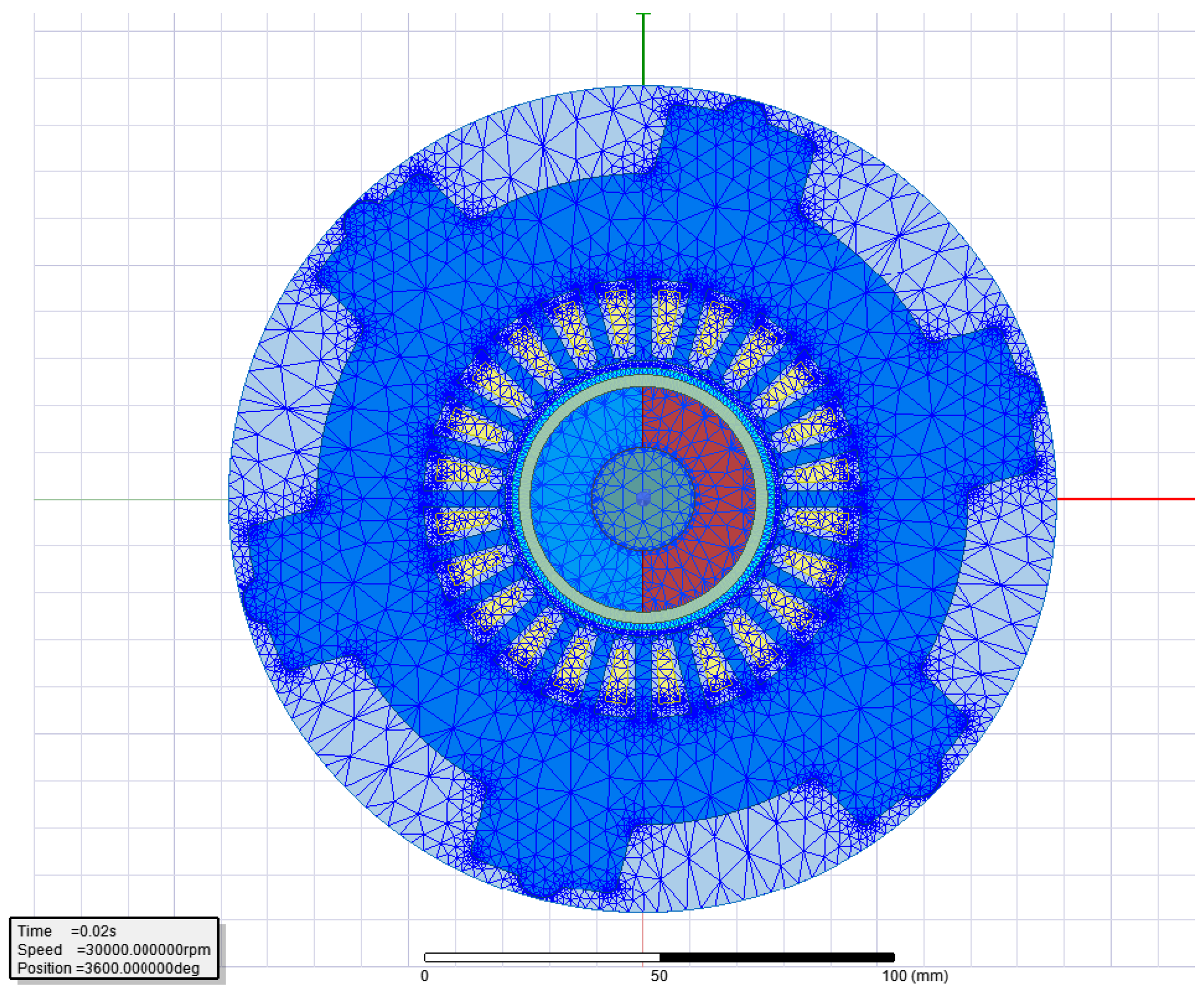
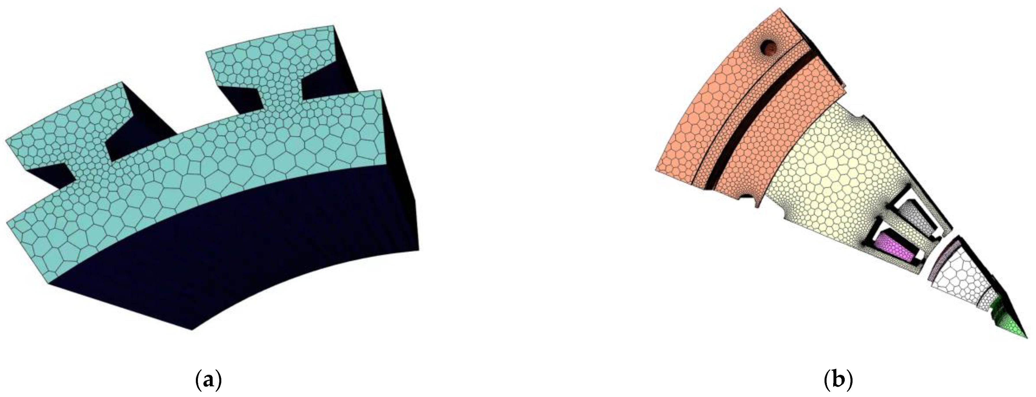
The key to temperature distribution analysis by finite element software is to divide the model in Mesh. Figure 2 shows the 2D grid of electromagnetic field analysis, and Figure 3 shows the grid division of the solution domain of the internal flow field of the magnetic suspension amorphous motor. The minimum mesh size is 0.5 mm and the maximum mesh size is 10 mm. According to the characteristics of different parts of the model, different partition methods are selected to discretize the solution model so as to obtain more accurate analysis results. In order to ensure that the loss data solved in the electromagnetic field is completely transferred to the temperature field, the three-dimensional model of the motor in the electromagnetic field and the temperature field should be exactly the same.
  • Considering the symmetry and heat transfer characteristics of the motor structure, as well as the requirements of the computer hardware, the 1/12 region of the motor is taken as the research object in order to improve the analysis efficiency.
  • In the solution domain of the temperature field analysis, the inlet boundary condition is the air speed of the cooling fan, and the cooling air speed varies with the motor speed. At 30 krpm, the inlet air speed is 70 m/s, the outlet is set as the pressure outlet boundary condition, the outlet pressure is 1 standard atmosphere, and the ambient temperature is 26.5 °C.
  • When the high speed motor speed becomes larger, the internal air Reynolds number is much higher for turbulent flow. Therefore, the standard k-ε model is used to solve the flow field. The rotor and air gap interface is the moving boundary, and the speed at the interface is set as the rotor speed.
  • The amorphous stator core, winding, rotor core, and permanent magnet in the solution domain are all heat sources. Due to the relatively low surface temperature of the external motor housing, the influence of radiation heat transfer is ignored.
  • The performance parameters of the materials used in each part of the motor are shown in Table 2. Since Fluent simulation can simulate the actual test environment of the motor, the parameter of convective heat transfer coefficient does not need input. Only parameters such as boundary conditions and material properties of the motor need to be input into the temperature field model.

2.3.2. Calculation of the Heat Source of the Electromagnetic Field

The electromagnetic loss generated during the operation of the motor is dissipated in the form of heat energy and becomes the heat source during the main operation of the motor, which mainly includes iron loss, copper loss, and eddy current loss. Accurate analysis of electromagnetic field is the premise of accurate calculation of temperature rise. When the temperature rises, the electromagnetic characteristics of some materials will change, leading to the change of electromagnetic parameters of the motor. The influence of temperature on remanent (Br) and coercive force (Hc) are given as (6) and (7). The copper loss of windings subjected to temperature change can be expressed as (8) [20,21]:
B r t = 1 + T P M T 0 α B r / 100 1 I L / 100 B r 0
H C t = 1 + T P M T 0 α C j / 100 1 I L / 100 H c 0
P C u = i = 1 3 I i 2 R a 1 + α T T 0
where Br0 and Hc0 are the remanence and coercivity at ambient temperature T0; αBr and αCj are the reversible temperature coefficients of Br and Hc; IL is the irreversible loss rate of Br; TPM is the working temperature of the magnet; T0 is the initial winding temperature; Ra is the initial resistance; α is the resistance temperature coefficient; Ii is the effective value of i phase current; and T is the true temperature value when the motor is working.
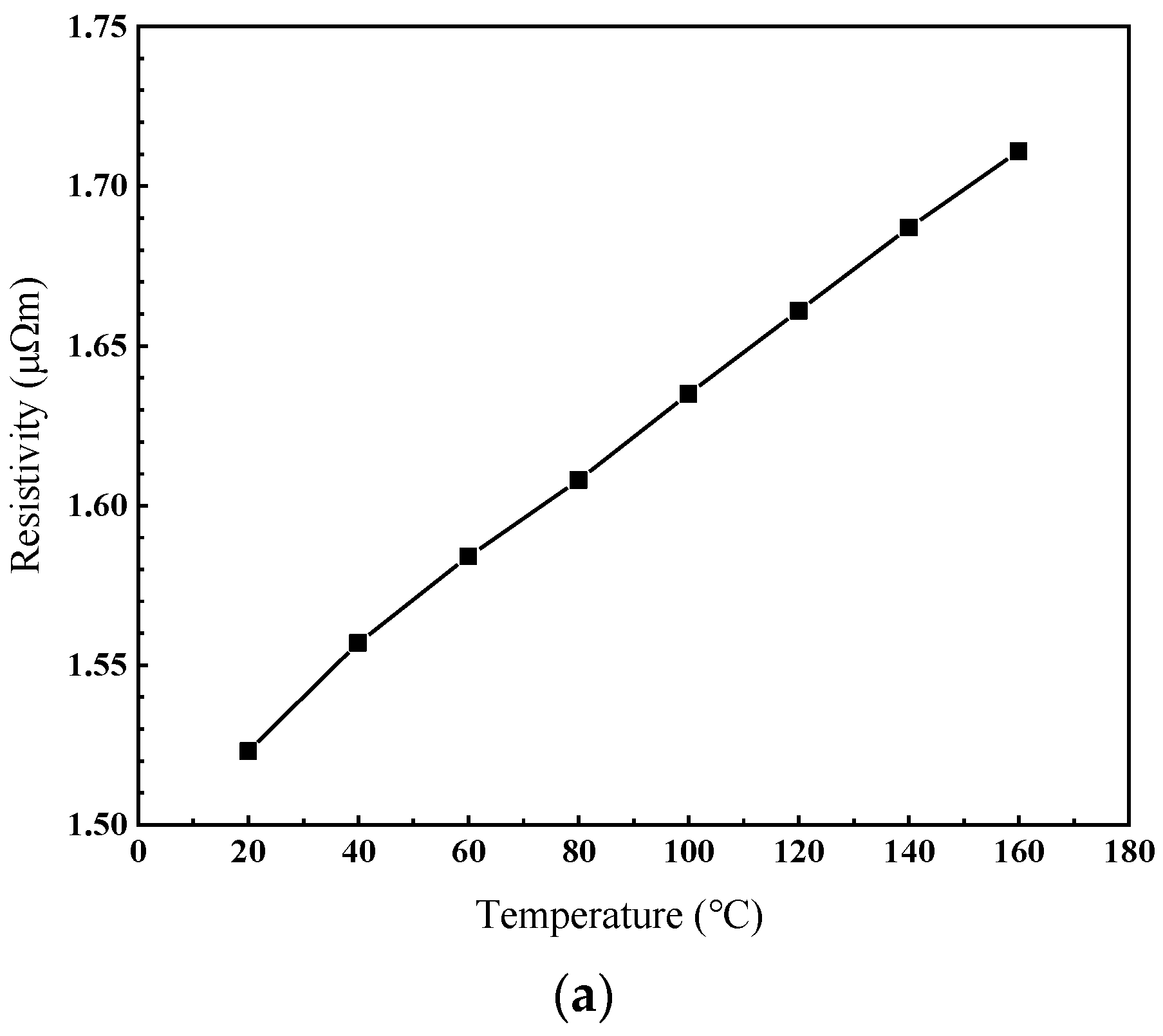
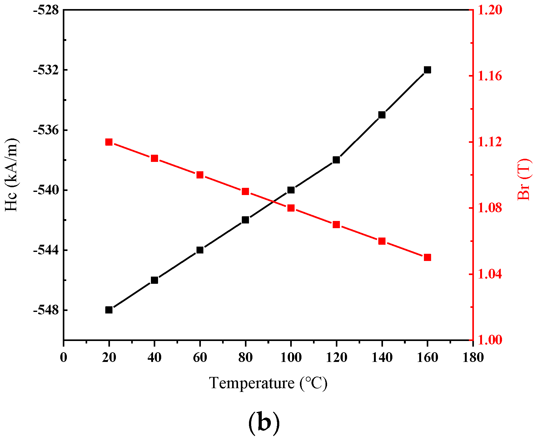
Figure 4a shows the change of winding resistivity with temperature. It can be seen that when the temperature increases from 20 °C to 16 °C, the resistivity of copper increases nearly twice. In addition, the change trend is approximately linear, mainly because the temperature coefficient of samarium cobalt material is small, and the control current of the motor does not increase significantly with the increase in temperature, while the winding resistance of the motor increases linearly with the increase of temperature. Figure 4b shows the changes of remanence and coercivity of permanent magnet with temperature. It can be seen that the influence of temperature on the permanent magnet is very significant, which will lead to irreversible demagnetization. In this paper, the motor stator core is selected as 1K101 amorphous alloy material. In the usual motor design work, the actual working temperature of the motor core material will be in the low temperature area of the amorphous material, and the physical properties of the material will not change significantly. Therefore, in this paper, it is assumed that the magnetic permeability of the core material of the motor does not change with temperature [22].
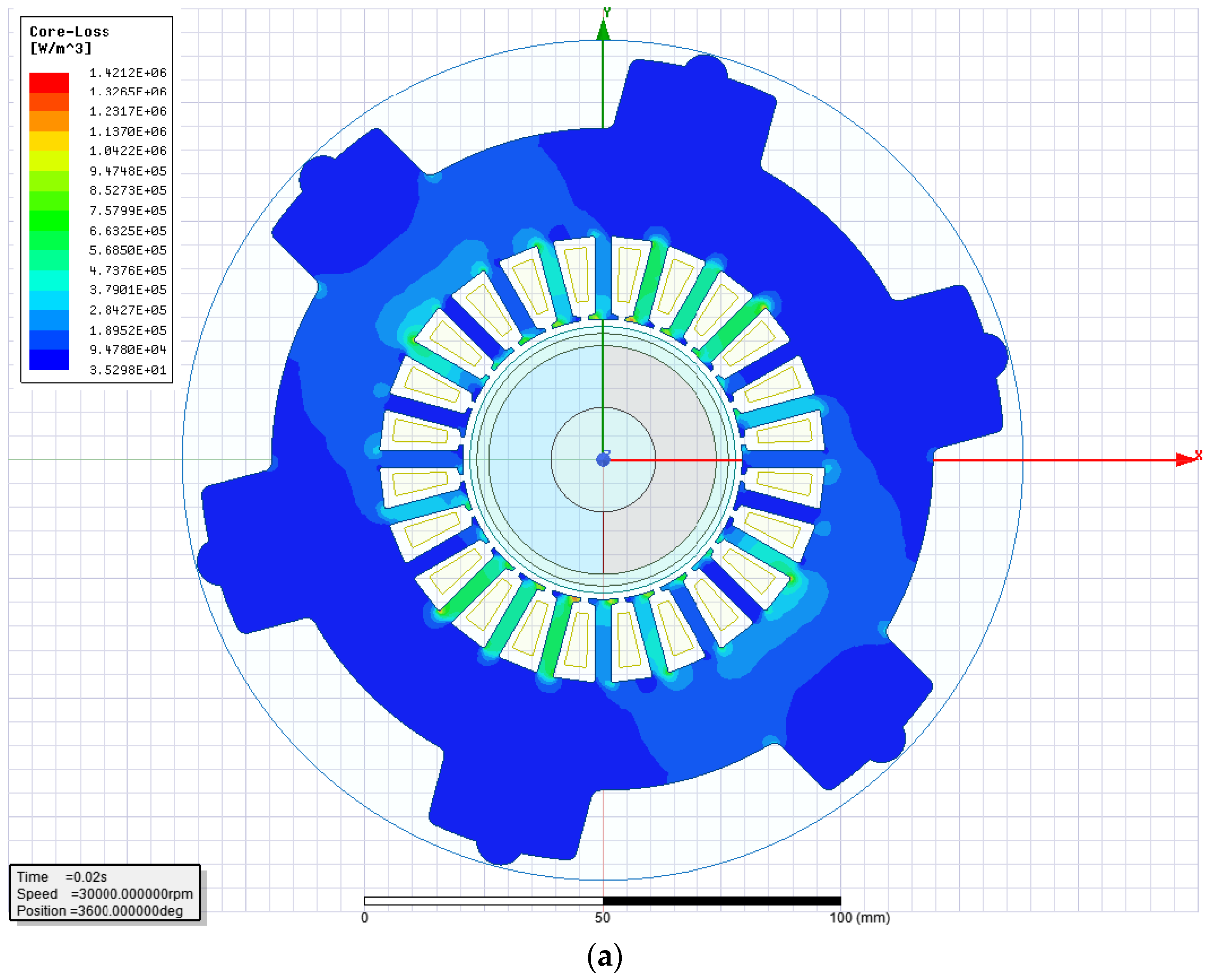
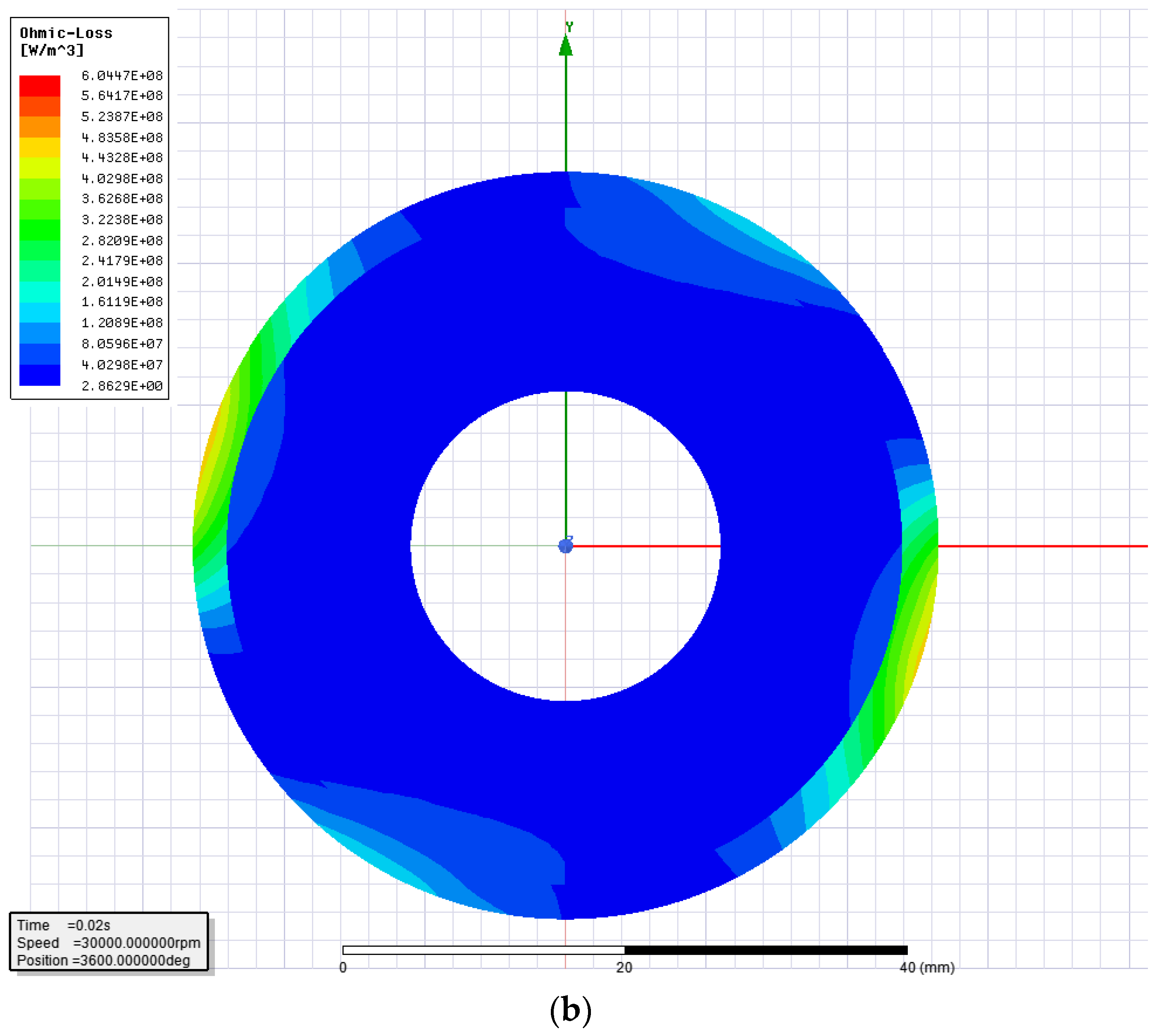
The density distribution of the stator and permanent magnet by the EM analysis method is shown in Figure 5. It can be seen that the motor loss is not evenly distributed in the actual operation process. It can be seen from Figure 5a that the loss density generated by the stator teeth is much larger than that of the stator yoke. Figure 5b shows that the eddy current loss on the surface of the permanent magnet sleeve is greater than that inside the permanent magnet. The titanium alloy material used in this paper shields the eddy current loss inside the permanent magnet to some extent, so the eddy current loss in the permanent magnet is less [23]. It can be seen that the conventional temperature rise analysis method cannot reflect the actual temperature distribution directly.

2.3.3. Calculation of Cooling Conditions for the Flow Field

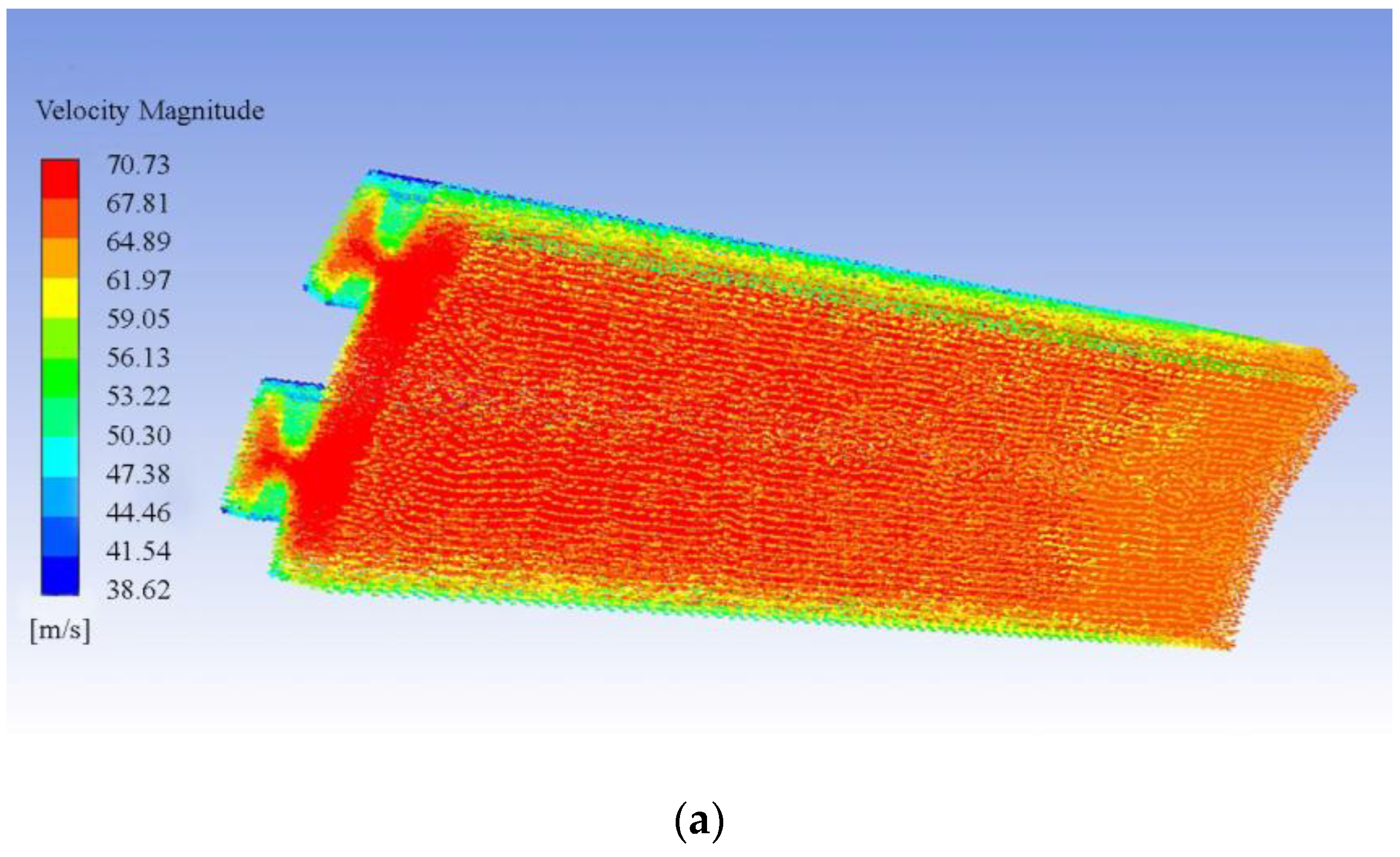
The internal temperature rise of the motor is affected by the loss of each part on the one hand, and related to the cooling capacity of the cooling medium on the other hand. CFD is used to simulate the cooling air speed generated by the cooling fan when the magnetic suspension motor is rotating. In the fluid analysis process, material performance is considered to be independent of temperature, and the velocity distribution of the air gap part is finally obtained through analysis, as shown in Figure 6. It can be seen that there is an obvious stratification in the velocity at the air gap. The velocity near the rotor and the turbulent region in the middle is 70 m/s, while the velocity in the laminar flow region near the stator is 38 m/s.
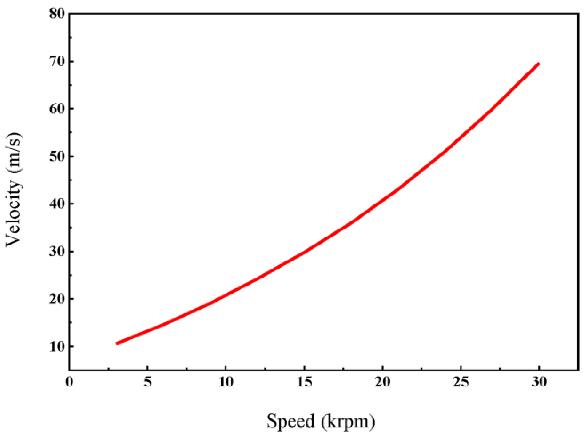
When the cooling fan rotates with the motor, it can be seen from Figure 7 that the speed increases from 3k rpm to 30k rpm, the maximum speed of the cooling air in the air gap increases from 10 m/s to 70 m/s, with an almost exponential growth. However, with the increase in rotational speed, the air friction loss also increases. The air friction loss caused by the friction between the outer surface and the air during high-speed operation of the rotor of the magnetic levitation motor is calculated as [2]:
P A ir = k C f π ρ a ω 3 r 4 L a
where k is the surface roughness; ρa is the gas density; ω is the rotor running angular speed; r is the rotor radius; La is the rotor core length.
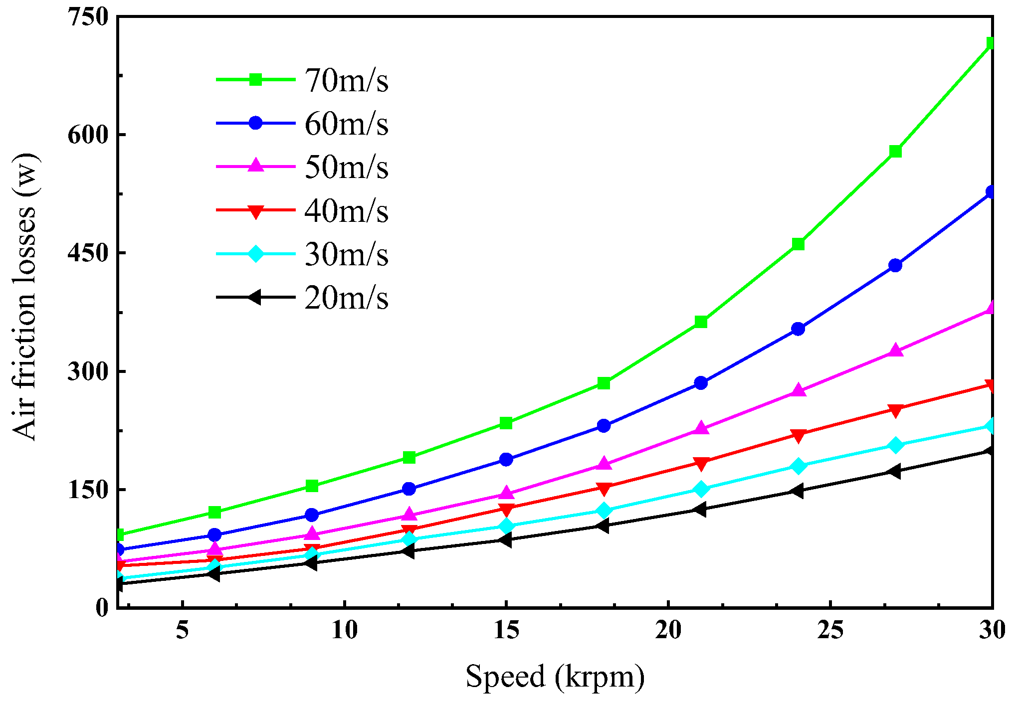
It can be seen from Figure 8, under the condition of the same cooling air speed, with the increase in motor speed, the air friction loss in the machine gradually increases, and the increasing gradient is larger and larger. At high speed, when the cooling air speed increased from 40 m/s to 70 m/s, the air friction loss value increased by more than 3 times, so in the motor for air cooling, there should be a combination of all aspects of the factors, not only the cooling air speed.

2.3.4. Coupled Iterative Analysis

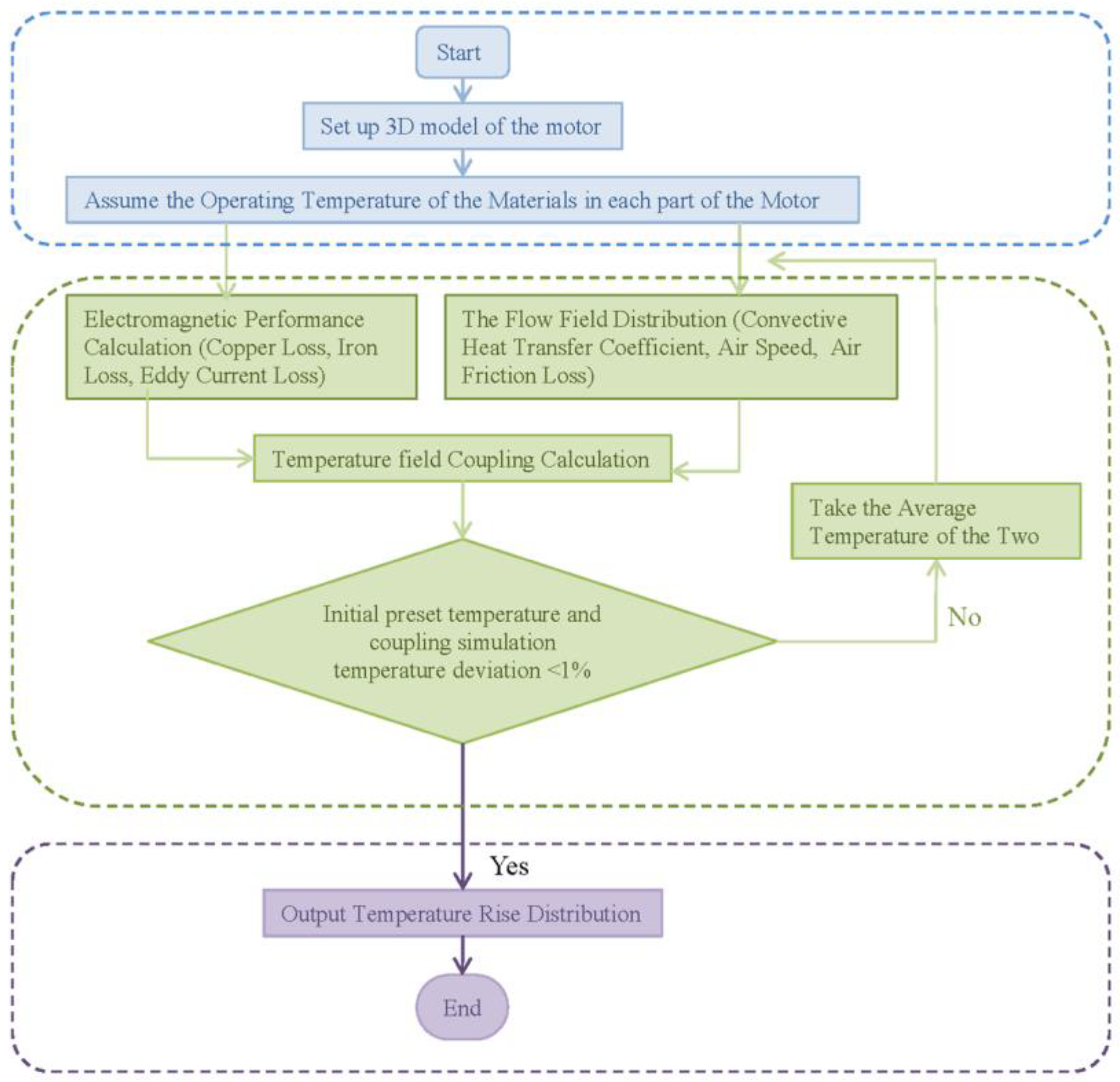
During the coupling analysis process, the initial temperature of the materials of each part of the motor in the initial state should be determined first, and then the losses of each part of the motor should be calculated according to the magnetic field distribution and the parameters of the prototype. The flow condition of the motor in the flow field is analyzed, and the convective condition and cooling boundary of the temperature field are obtained. The loss will be mapped as a heat source to the motor temperature field solution domain, and the boundary conditions obtained by the flow field will be input, and the solver will simulate the motor temperature rise process at this step size, so as to determine the overall distribution of motor temperature at the next moment. According to the new temperature distribution of the motor, considering the changes of various parameters of the motor material and flow state affected by temperature, the distribution of the electromagnetic field and flow field of the motor are recalculated, and the cycle from the electromagnetic field flow field to the temperature field is repeated. The calculation is carried out until the predetermined solution time is reached and the calculation is finished. Finally, the temperature rise curve of the motor in operation and the temperature field distribution at each time can be obtained. The specific coupling flow is shown in Figure 9.
The electromagnetic heat flow coupling iterative calculation is carried out according to the flow chart in Figure 9, and the coupling iterative analysis is carried out for the motor under the working condition of 35 kw and 30 krpm. The iterative data is shown in Table 3. It can be seen that after nine iterations, the error between the initial preset temperature and the final coupled iteration temperature is less than 1%. At this time, the overall temperature of all parts of the motor is below 110 °C, the highest temperature of the winding part is 109 °C, the highest temperature of the permanent magnet is 80 °C, and the highest temperature of the stator is 108 °C.

3. Results

3.1. Comparison with the Traditional Temperature Rise Analysis Method

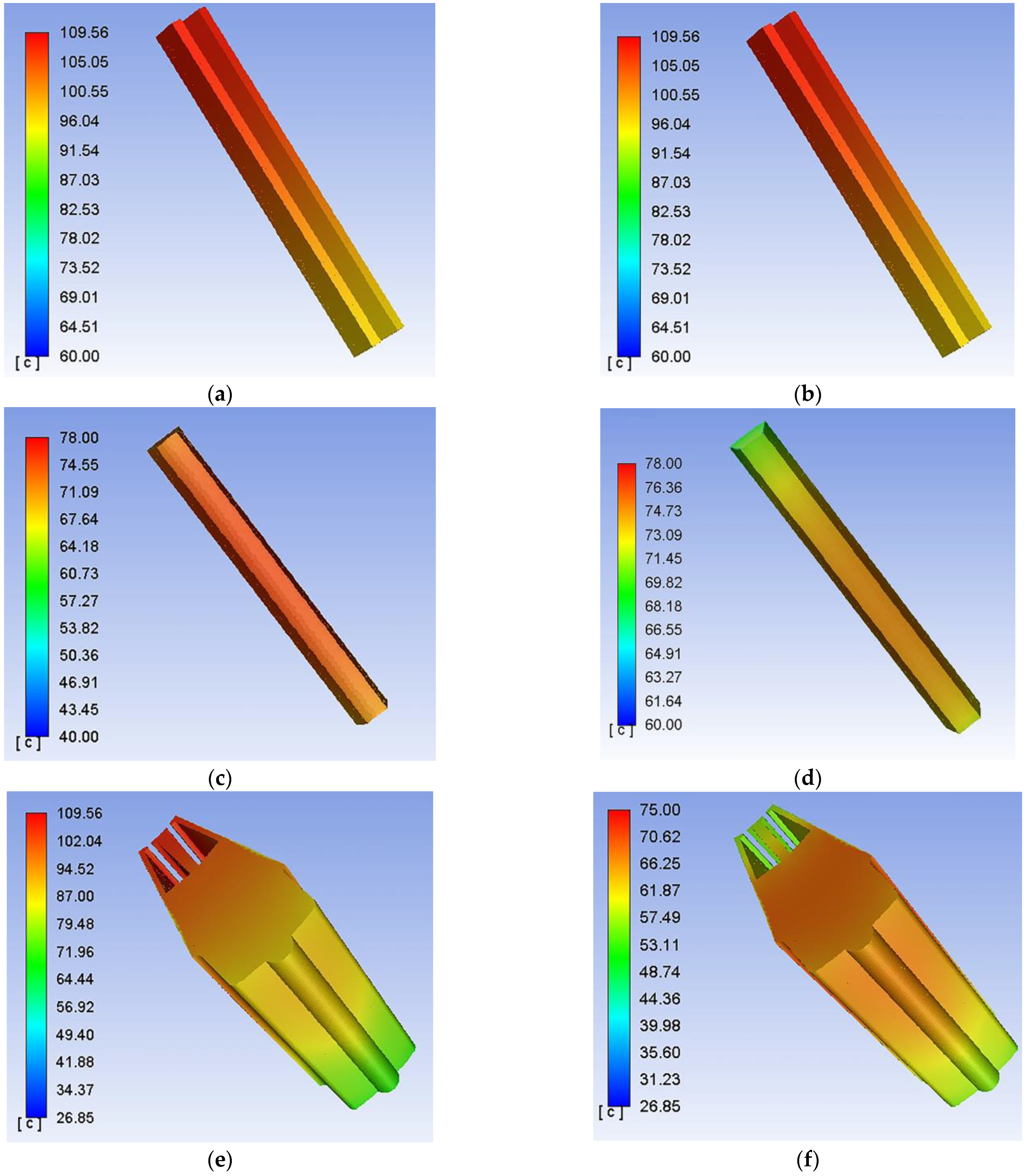
The temperature analysis results of the motor at 30 krpm are shown in Figure 10. By comparing the finite element coupling simulation method with the traditional temperature field analysis method, it can be seen that although the overall temperature of the motor is not very different, the temperature distribution of each part is. It can be seen from the ETFC method that the highest temperature of the stator appears at the stator slot, and the highest temperature of the permanent magnet appears at the surface. Combined with Figure 5, it can be seen that the loss density generated in these two places is relatively high, so the temperature rise is also relatively large. However, traditional method of temperature rise analysis show the opposite result, that is, the stator teeth and permanent magnet surface temperatures are relatively low. This is why the traditional method of temperature rise analysis assumes that the heat source is uniformly distributed in the process of analysis. Where the cooling air is in contact with, the heat loss is fast, so the temperature is low, which is not consistent with the temperature distribution in the actual operation of the motor. The results show that the temperature rise analysis of the ETFC analysis method is closer to the actual situation of motor operation.

3.2. Temperature Rise Analysis under Different Working Conditions

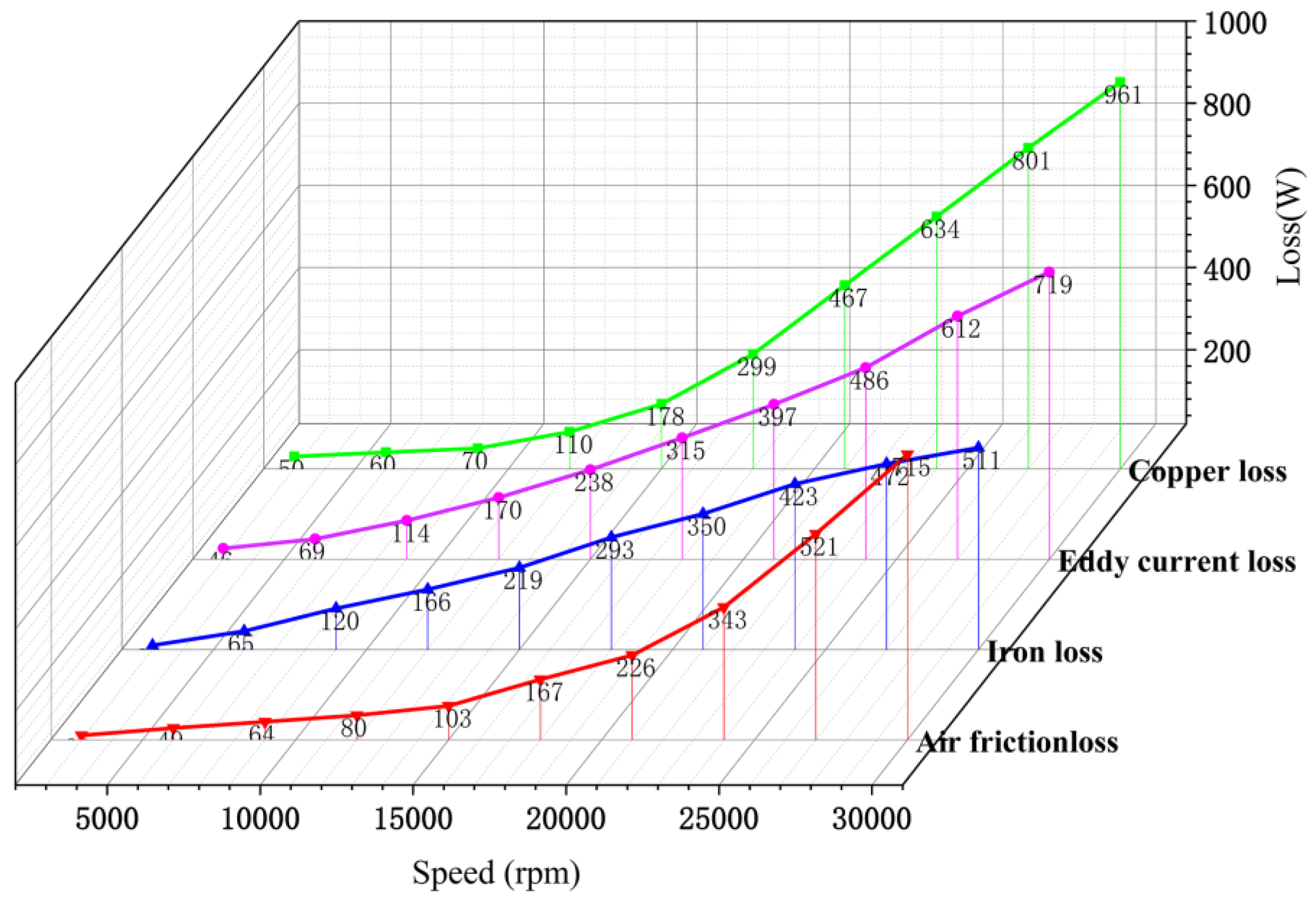
In order to further verify the applicability of the method in different working conditions, the temperature distribution of the motor at 3000 rpm~30,000 rpm was analyzed, respectively. Under different working conditions, the electromagnetic parameters of each part of the material are different, resulting in different losses. Through multiple coupling iterations, the loss distribution under different rotational speeds is obtained, as shown in Figure 11. It can be seen that with the increase in rotational speed, the loss almost increases exponentially, and the heat generated is also amorphous.
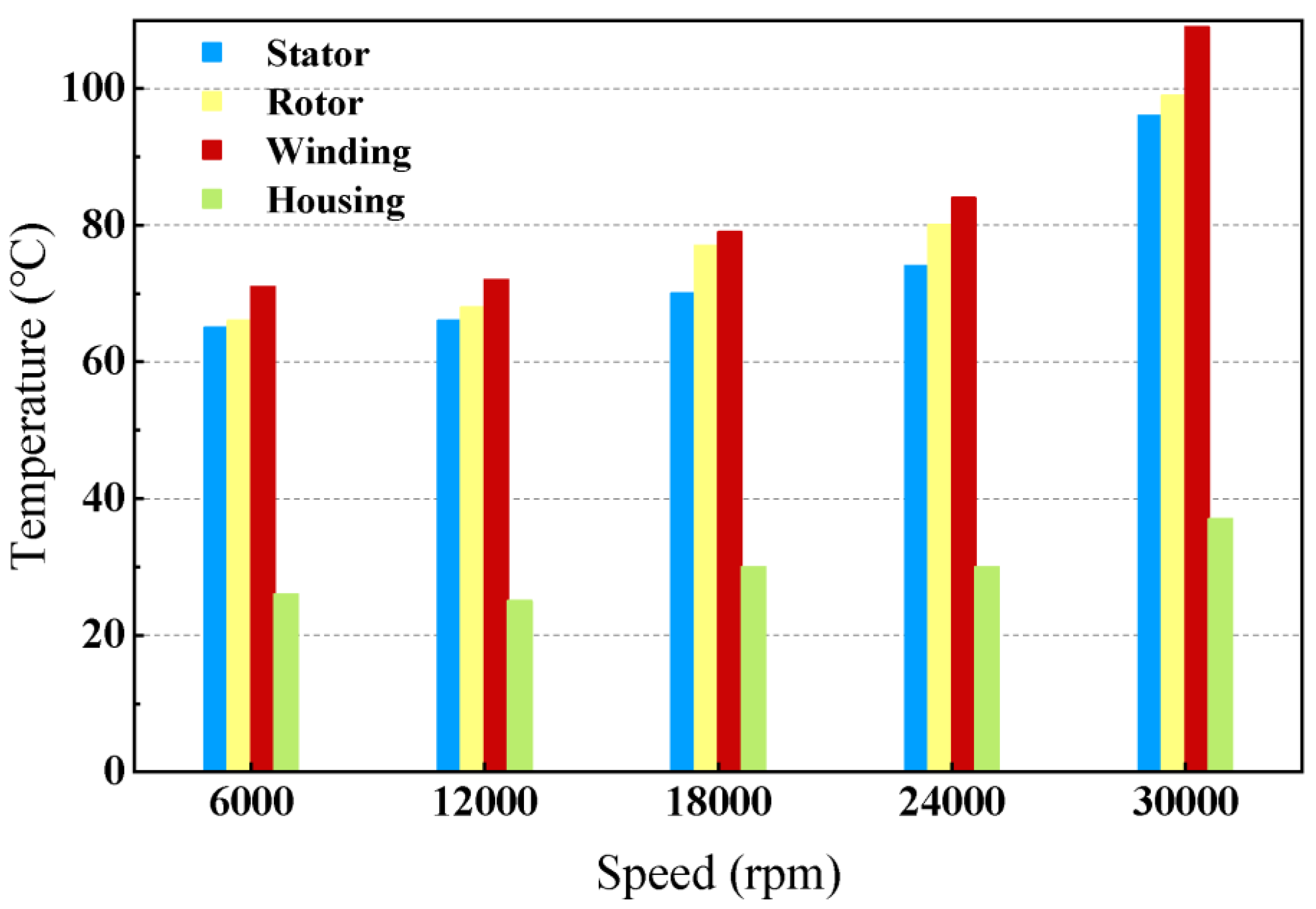
Finally, the temperature distribution of the motor at different speeds is shown in Figure 12. It can be seen that the overall temperature distribution of the motor is relatively stable under the condition of low rotational speed. Although the heat production will increase with the increase in rotational speed, the increase of cooling wind speed can also effectively reduce the temperature of the motor. However, as the rotational speed increases to more than 24 krpm, the loss density increases almost exponentially, so the temperature of the motor also increases relatively. For a high-speed and high-power motor, it is very important to choose a good cooling method.

3.3. Experimental Verification

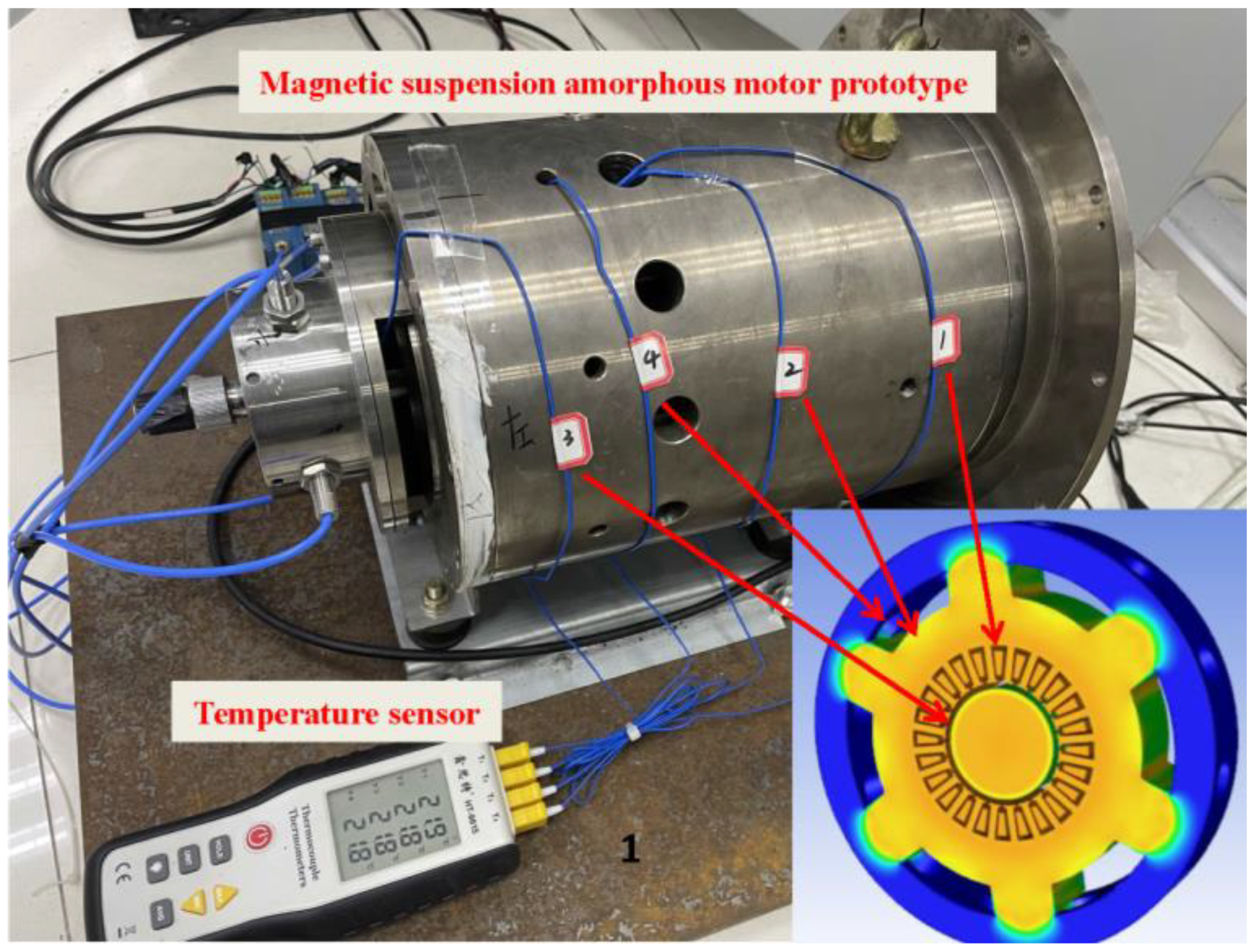
In order to verify the accuracy of the simulation results, an experimental platform is built for the temperature rise experiment. In the manufacturing process of the prototype, the thermal resistance temperature sensor is embedded in the winding end, stator, and rotor position for convenient measurement. The test platform is shown in Figure 13. Four key parts are selected for measurement. Where, site 1 is the winding surface, site 2 is the stator yoke, site 3 is the outer surface of the rotor, and site 4 is the housing.
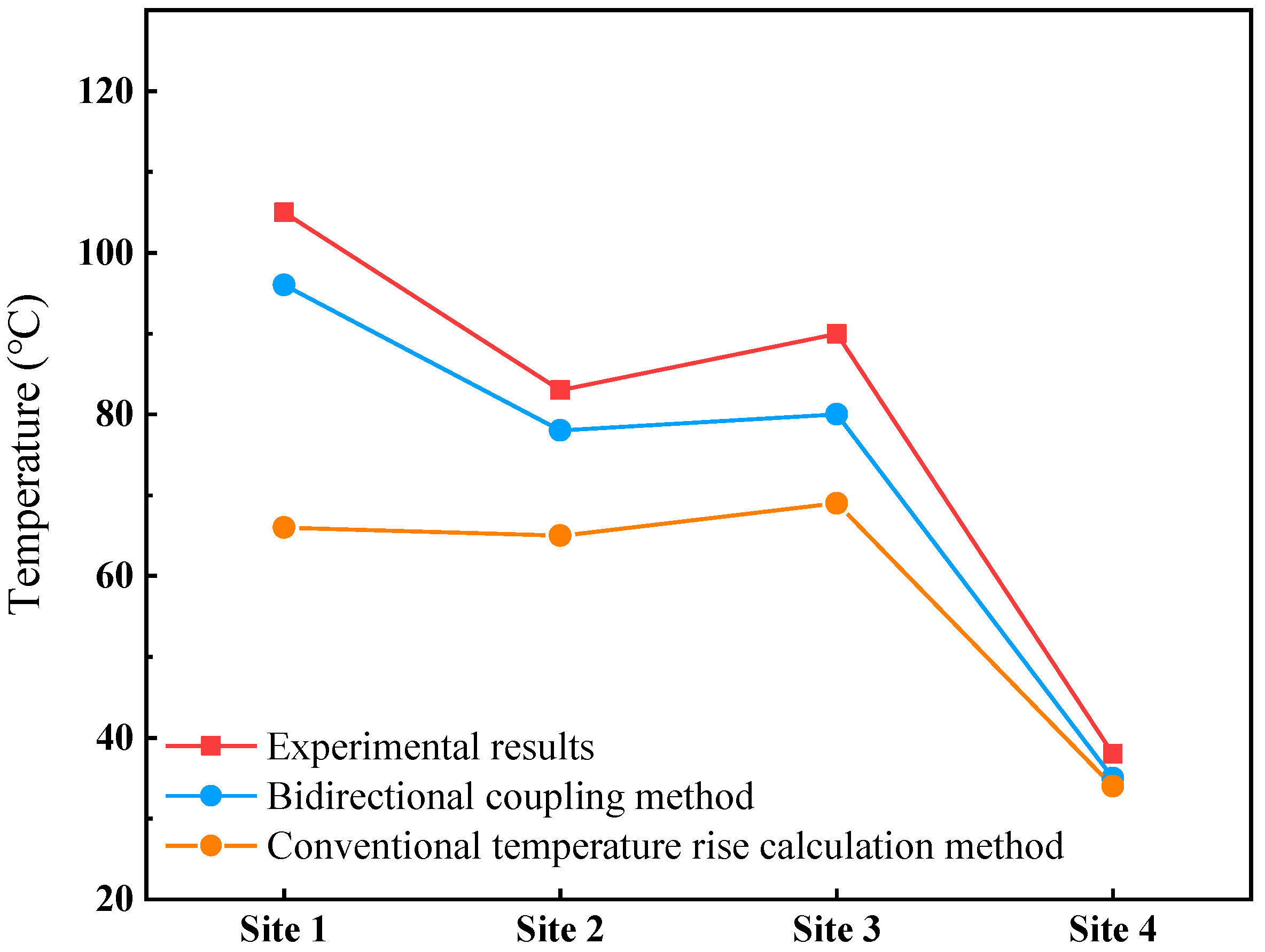
The temperature rise of the MSAM used in this paper is essentially stable after 96 min of operation. The experimental results of this paper are the average of the six test results, and the comparison between simulation and experimental results is shown in Figure 14. It can be seen from the experimental results that the temperature rise of the motor mainly occurs at site 1, where the temperature is 105 °C, site 2 is 85 °C, site 3 is 90 °C, and site 4 is 38 °C. Compared with the experimental and simulation results, it can be seen that for the ETFC method, the overall error is less than 10 °C. The rotor error at site 3 is larger because the use of magnetic suspension support increases the difficulty of rotor measurement. The error at site 1 is 6 °C, because the winding structure is derived from the equivalent winding, there is an error with the actual structure, but the above errors are within the allowable range. As can be seen from the results of the traditional temperature rise analysis method, the maximum error of site 1 and site 3 is 30 °C. Combined with Figure 10, it can be seen that the traditional temperature rise analysis method is not consistent with the actual temperature, so the error is large.
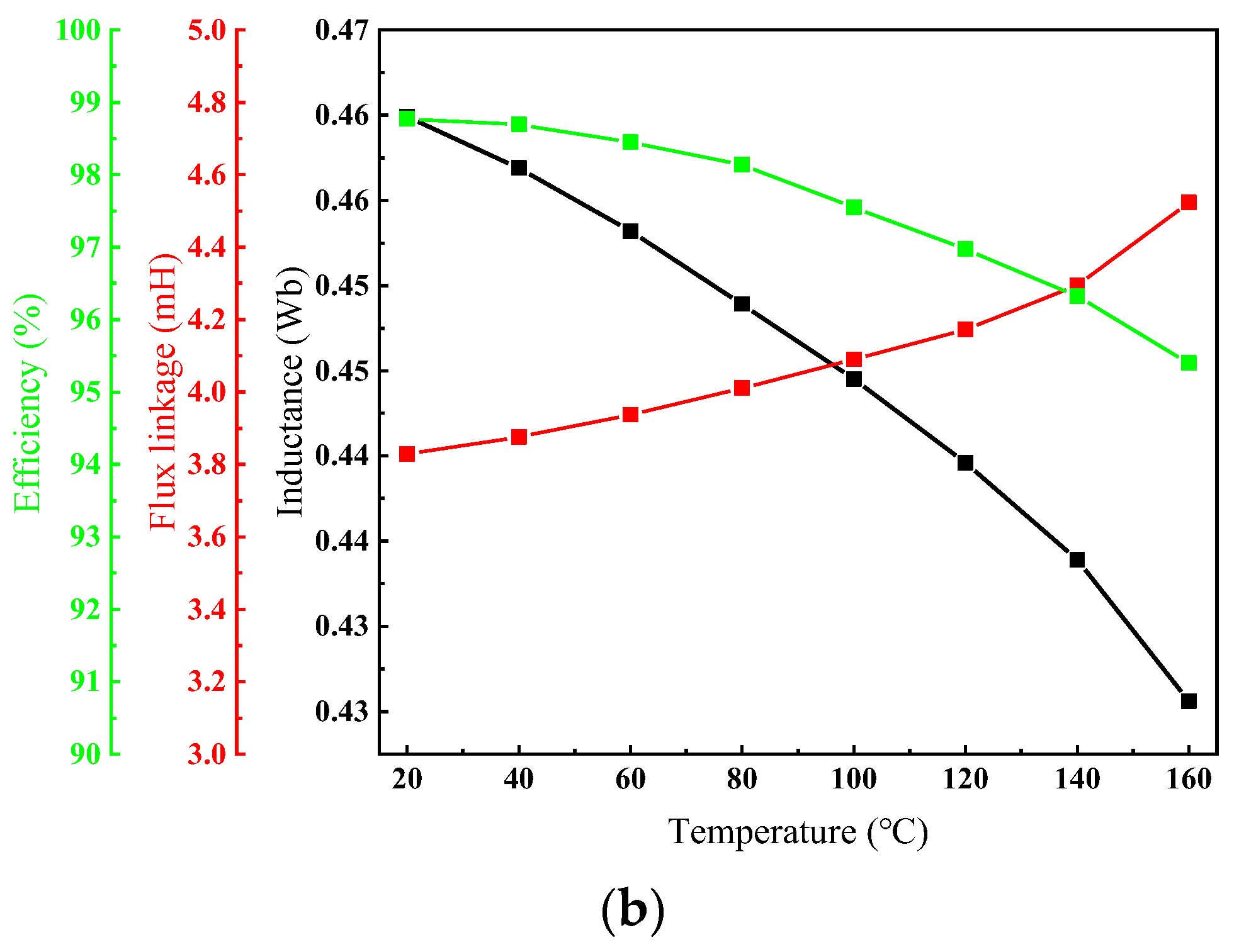
The temperature characteristics of the motor at different temperatures are tested, as shown in Figure 15. Figure 15a shows that when the temperature increases from 20 °C to 160 °C, the no-load back electromotive force and radial air gap magnetic density of the motor are reduced by 12% and 10%, respectively, and the winding current increases by 3%. As shown in Figure 15b, the inductance of the motor increases, but the flux and the efficiency of the motor both decrease, and the efficiency decreases by 3%. It can be seen that the effect of temperature on the performance of the motor is very important. Therefore, the cooling of high-speed and high-power motors cannot be ignored.

4. Conclusions

In this paper, the loss and thermal performances of a high-speed magnetic suspension amorphous motor are studied by using the magneto-heat flow coupling method, and the accuracy of simulation results is verified by the experimental results.
  • Updating the electromagnetic properties of materials through multiple coupling iterations is the key to improve the precision of motor loss analysis.
  • Compared with the traditional thermal analysis method, the coupling method can achieve accurate data transmission, and the analysis results are closer to the actual operation of the motor.
  • With the increase in the cooling rate, air friction loss will increase rapidly. However, for the magnetic levitation motor, due to the increase in air gap width, axial cooling air is sufficient, and forced air cooling can effectively cool the motor rotor.
  • The temperature rise measurement shows that the coupling temperature analysis results are in good agreement with the test results, and the overall error is less than 10 °C. The analysis results of this paper are of great significance to improve the analysis accuracy of motor loss and temperature rise and to accurately predict the temperature rise in the motor design stage.

Author Contributions

Conceptualization, X.H. and G.S.; methodology, X.H.; software, Y.L.; formal analysis, X.H.; investigation, X.H.; resources, L.W.; writing—original draft preparation, X.H.; writing—review and editing, G.S., Y.L., J.Y. and Y.S.; supervision, Y.S.; project administration, L.W.; funding acquisition, L.W. All authors have read and agreed to the published version of the manuscript.

Funding

This research was supported by the National Key Research and Development Program of China (No. 2021YFB3500205), the Key Research and Development Plan of Shandong Province (No. 2021CXGC010309, No. 2022CXGC020307) and Natural Science Foundation of Shandong Province [project No. ZR2020ME119].

Data Availability Statement

Not applicable.

Conflicts of Interest

The authors declare no conflict of interest.

References

  1. Ren, X.; Le, Y.; Han, B. System Electromagnetic Loss Analysis and Temperature Field Estimate of a Magnetically Suspended Motor. Prog. Electromagn. Res. M 2017, 55, 51–61. [Google Scholar] [CrossRef] [Green Version]
  2. Huang, Z.; Fang, J.; Liu, X.; Han, B. Loss Calculation and Thermal Analysis of Rotors Supported by Active Magnetic Bearings for High-Speed Permanent-Magnet Electrical Machines. IEEE Trans. Ind. Electron. 2016, 63, 2027–2035. [Google Scholar] [CrossRef]
  3. Dong, B.; Wang, K.; Han, B.; Zheng, S. Thermal Analysis and Experimental Validation of a 30 kW 60,000 r/min High-Speed Permanent Magnet Motor with Magnetic Bearings. IEEE Access 2019, 7, 92184–92192. [Google Scholar] [CrossRef]
  4. Liu, X.; Liu, G.; Han, B. A Loss Separation Method of a High-Speed Magnetic Levitated PMSM Based on Drag System Experiment without Torque Meter. IEEE Trans. Ind. Electron. 2019, 66, 2976–2986. [Google Scholar] [CrossRef]
  5. Hu, Y.; Chen, B.; Jia, J.; Zhang, X.; Liu, J. Design and Analysis of Cooling System for High Speed PM Synchronous Motor with Magnetic Bearings. In Proceedings of the 2018 21st International Conference on Electrical Machines and Systems (ICEMS), Jeju, Republic of Korea, 7–10 October 2018; pp. 228–233. [Google Scholar]
  6. Cai, X.; Cheng, M.; Zhu, S.; Zhang, J. Thermal Modeling of Flux-Switching Permanent-Magnet Machines Considering Anisotropic Conductivity and Thermal Contact Resistance. IEEE Trans. Ind. Electron. 2016, 63, 3355–3365. [Google Scholar] [CrossRef]
  7. Souhil, S.; Harmand, S.; Laloy, D. Study of the thermal behavior of a synchronous motor with permanent magnets. Int. J. Eng. 2009, 3, 229–256. [Google Scholar]
  8. Rostami, N.; Feyzi, M. Lumped-Parameter Thermal Model for Axial Flux Permanent Magnet Machines. IEEE Trans. Magn. 2013, 49, 1178–1184. [Google Scholar] [CrossRef]
  9. Armor, A.; Chari, M. Heat flow in the stator core of large turbine-generators, by the method of three-dimensional finite elements part Ⅱ: Temperature distribution in the stator iron. IEEE Trans. Power Appar. Syst. 1976, 95, 1657–1668. [Google Scholar] [CrossRef]
  10. Joo, D.; Cho, J.H.; Woo, K.; Kim, B.T.; Kim, D.K. Electromagnetic Field and Thermal Linked Analysis of Interior Permaanent-Magnet Synchronous Motor for Agricultural Electric Vehicle. IEEE Trans. Magn. 2011, 47, 4242–4245. [Google Scholar] [CrossRef]
  11. Li, G.; Ojeda, J.; Hoang, E.; Gabsi, M.; Lecrivain, M. Thermal–electromagnetic analysis for driving cycles of embedded flux-switching permanent-magnet motors. IEEE Trans. Veh. Technol. 2012, 61, 140–151. [Google Scholar] [CrossRef] [Green Version]
  12. Tang, H.; Zhang, M.; Dong, Y.; Li, W.; Li, L. Influence of the opening width of stator semiclosed slot and the dimension of the closed slot on the magnetic field distribution and temperature field of the permanent magnet synchronous motor. IET Electr. Power Appl. 2020, 14, 1642–1652. [Google Scholar] [CrossRef]
  13. Jungreuthmayer, C.; Bäuml, T.; Ganchev, M.; Kapeller, H.; Haumer, A. A Detailed Heat and Fluid Flow Analysis of an Internal Permanent Magnet Synchronous Machine by Means of Computational Fluid Dynamics. IEEE Trans. Ind. Electron. 2012, 59, 4568–4578. [Google Scholar] [CrossRef]
  14. Li, W.; Qiu, H.; Zhang, X.; Yi, R. Influence of Copper Plating on Electromagnetic and Temperature Fields in a High-Speed Permanent-Magnet Generator. IEEE Trans. Magn. 2012, 48, 2247–2253. [Google Scholar]
  15. Chen, S.; Zhang, Q.; He, B.; Hui, D.; Huang, S. Thermal Analysis of High Density Permanent Magnet Synchronous Motor Based on Multi Physical Domain Coupling Simulation. J. Electr. Eng. Technol. 2017, 12, 91–99. [Google Scholar] [CrossRef] [Green Version]
  16. Shafigh, N.; Huang, Z.; Andreas, K.; Oskar, W.; Mats, L. Thermal Modeling of Directly Cooled Electric Machines Using Lumped Parameter and Limited CFD Analysis. IEEE Trans. Energy Convers. 2013, 28, 979–990. [Google Scholar]
  17. Tong, W.; Dai, S.; Wu, S.; Tang, R. Performance Comparison Between an Amorphous Metal PMSM and a Silicon Steel PMSM. IEEE Trans. Magn. 2019, 55, 1–5. [Google Scholar] [CrossRef]
  18. Shotaro, O.; Nicolas, D.; Yoshiyuki, K.; Masaharu, I.; Keisuke, F. Core Loss Reduction of an Interior Permanent-Magnet Synchronous Motor Using Amorphous Stator Core. IEEE Trans. Magn. 2016, 52, 2261–2268. [Google Scholar]
  19. Liu, X.; Yu, H.; Shi, Z.; Xia, T.; Hu, M. Electromagnetic-fluid-thermal field calculation and analysis of a permanent magnet linear motor. Appl. Therm. Eng. 2018, 129, 802–811. [Google Scholar] [CrossRef]
  20. Jiang, Y.; Wang, D.; Chen, J.; Zhang, Q.; Xuan, T. Electromagnetic-Thermal-Fluidic Analysis of Permanent Magnet Synchronous Machine by Bidirectional Method. IEEE Trans. Magn. 2018, 54, 1–5. [Google Scholar] [CrossRef]
  21. Wrobel, R.; Staton, D.; Lock, R.; Booker, J.; Drury, D. Winding Design for Minimum Power Loss and Low-Cost Manufacture in Application to Fixed-Speed PM Generator. IEEE Trans. Ind. Appl. 2015, 51, 3773–3782. [Google Scholar] [CrossRef] [Green Version]
  22. Yang, M.; Li, Y.; Yang, Q.; Lin, Z.; Yue, S.; Wang, H. Magnetic Properties Measurement and Analysis of High Frequency Core Materials Considering Temperature Effect. IEEE Trans. Appl. Supercond. 2020, 30, 1–5. [Google Scholar] [CrossRef]
  23. Han, T.; Wang, Y.; Shen, J. Analysis and Experiment Method of Influence of Retaining Sleeve Structures and Materials on Rotor Eddy Current Loss in High-Speed PM Motors. IEEE Trans. Ind. Appl. 2020, 56, 4889–4895. [Google Scholar] [CrossRef]
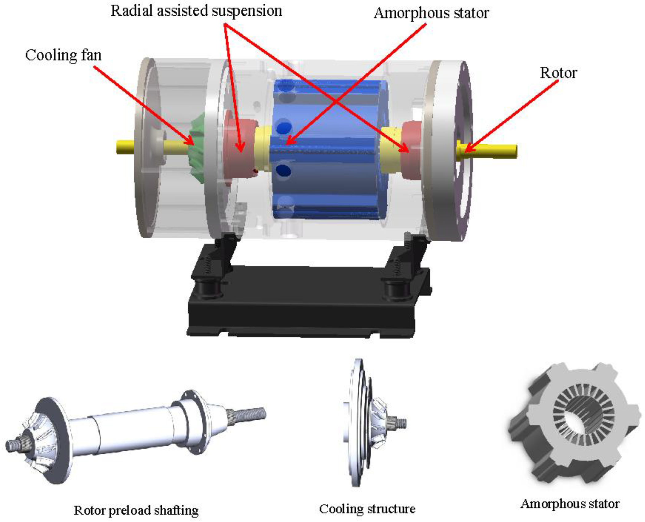
Figure 1. Motor structure.
Machines 11 00364 g001
Figure 2. Two-dimensional electromagnetic model grid.
Machines 11 00364 g002
Figure 3. Three-dimensional mesh: (a) air gap structure grid; (b) motor thermal analysis grid.
Machines 11 00364 g003
Figure 4. The motor structure: (a) effect of temperature on the resistivity of copper; (b) effects of temperature on Br and Hc of permanent magnets.
Machines 11 00364 g004aMachines 11 00364 g004b
Figure 5. Loss density distribution: (a) stator iron loss density distribution; (b) eddy current loss density distribution of permanent magnet.
Machines 11 00364 g005aMachines 11 00364 g005b
Figure 6. Distribution of air gap speed: (a) axial distribution; (b) radial distribution.
Machines 11 00364 g006aMachines 11 00364 g006b
Figure 7. Cooling air speed at different rotational speeds.
Machines 11 00364 g007
Figure 8. Air friction loss at different rotation speeds and cooling air speeds.
Machines 11 00364 g008
Figure 9. Coupling analysis process.
Machines 11 00364 g009
Figure 10. Temperature distribution of each part of the motor: (a) winding temperature obtained by CTFC method; (b) winding temperature obtained by conventional temperature rise calculation method; (c) magnet temperature obtained by CTFC method; (d) magnet temperature obtained by conventional temperature rise calculation method; (e) stator temperature obtained by CTFC method; (f) stator temperature obtained by conventional temperature rise calculation method.
Machines 11 00364 g010
Figure 11. Loss distribution at different speeds.
Machines 11 00364 g011
Figure 12. Temperature distribution at different speeds.
Machines 11 00364 g012
Figure 13. Temperature rise experiment platform.
Machines 11 00364 g013
Figure 14. Comparison of experimental and simulation results.
Machines 11 00364 g014
Figure 15. Effect of temperature on motor performance: (a) No-load performance; (b) Load performance.
Machines 11 00364 g015aMachines 11 00364 g015b
Table 1. Main design parameters of the motor.
ParametersValue
Rated power/kW37.5
Rated speed/rpm30,000
Rated voltage/V380
Winding layersingle
Slot number24
Stator outer diameter mm139
Stator inter diameter/mm58.85
Rotor outer diameter/mm53
Rotor inter diameter/mm22
Poles number2
Table 2. Motor material parameters.
ParametersMaterialsDensity
(kg/m3)
Heat Capacity J/(kg•K)Specific Thermal Conductivity (W/m/K)
StatorAmorphous718043018
MagnetTi-alloy45006128
Rotor sleeveSm2Co17830050023
WindingCopper8930386400
HousingSteel785050015
StatorAmorphous718043018
Table 3. Coupling iteration result.
Number of Iterations6789
Initial preset temperatureMagnet72.775.57777.5
Stator102.4105.7107.6108.3
Winding102106108109
Coupling simulation temperatureMagnet78.378.57878
Stator109109.5109108
Winding110110110109
error7.7%3.9%1.3%0.7%
Disclaimer/Publisher’s Note: The statements, opinions and data contained in all publications are solely those of the individual author(s) and contributor(s) and not of MDPI and/or the editor(s). MDPI and/or the editor(s) disclaim responsibility for any injury to people or property resulting from any ideas, methods, instructions or products referred to in the content.