Article

Research on Multi-Body Collision Dynamics of Ball Cage Flexible Drill Pipe Considering Borehole Curvature

1
College of Pipeline and Civil Engineering, China University of Petroleum (East China), Qingdao 266580, China
2
CNPC Tianjin Bo-Xing Engineering Science &Technology Co., Ltd., Tianjin 300451, China
*
Author to whom correspondence should be addressed.
Machines 2023, 11(3), 357; https://doi.org/10.3390/machines11030357
Submission received: 6 February 2023 / Revised: 28 February 2023 / Accepted: 3 March 2023 / Published: 6 March 2023
(This article belongs to the Section Electromechanical Energy Conversion Systems)

Abstract

:
A ball cage flexible drill pipe is a new type of ultra-short-radius drilling tool, which consists of multiple flexible joints hinged together. During the drilling process, the flexible members will come into contact and wear, which reduces the efficiency of load transfer. The multi-body collision contact dynamics model was proposed to study the performance of the ball cage flexible drill pipe. The method considered the influence of the borehole curvature. The kinematic equations of the ball cage flexible drill pipe were established. The Lankarani–Nikravesh collisional contact model was used to characterize the normal contact force, and the Coulomb friction model was used to describe the tangential contact force. The multi-body motion state of the flexible drill pipe was simulated, the contact force distribution of the flexible drill pipe during the motion cycle was analyzed, and the influence of the borehole curvature radius on the size of the flexible joints and the contact force was studied. The results show that the running form of the ball cage flexible drill pipe shows a “folded” shape compared with the initial form; the contact force of different flexible joints is in a state of fluctuation; the normal contact force is much larger than the tangential contact force; the matching relationship between the borehole curvature and the length and radius of the flexible joints is derived, which provides criteria for the design of the flexible joints to ensure the reliability of the flexible drill pipe in large curvature borehole; the borehole curvature has an important influence on the collision contact force and load transfer efficiency of flexible drill pipe.

1. Introduction

Ultra-short-radius drilling technology is a new efficient skill for developing special oil–gas reservoirs and the remaining oil in old fields [1]. The basic principle is that the drilling pressure and torque are transferred to the drill bit by the flexible drilling tool under the action of the whipstocks to form a new borehole with a curvature radius of 1~3 m. The flexible drilling tool consists of a guide tube, a flexible drill pipe, and a drill bit (as shown in Figure 1); the guide tube can produce a certain degree of lateral bending when subjected to axial force, which guides the movement of the flexible drill pipe and transmits the drilling pressure to the drill bit through the lower connector; the flexible drill pipe is hinged by multiple flexible joints, which can bend with the guide tube and transmit the torque to the drill bit through the lower connector.
Currently, artificial intelligence is proving to be a real enabler in the evolution of the oil and gas industry. Artificial intelligence has significant advantages in structure and material performance prediction [2,3], performance prediction under different working conditions [4], the optimization of structure design, response prediction under different driving schemes [5], etc. Artificial intelligence can be used to optimize the structure and predict the performance of ultra-short-radius drilling technology in the application process so that it can play a more important role in the development of special oil and gas reservoirs and the remaining oil of old oil fields.
A flexible drill pipe is a key structure for realizing ultra-short-radius lateral drilling, which consists of multiple flexible joints hinged together. Experts from home and abroad have developed different types of flexible drill pipes. Cao [1] et al. designed an ultra-short-radius radial horizontal drilling tool, which consists of a high-strength flexible drill pipe, a follow-up pipe, and a positioning whipstock. Luo [6] established a nonlinear finite element model of the universal flexible drill pipe and analyzed the dynamic characteristics of the flexible drill pipe and the guide tube. Our group [7] developed a new type of ball cage flexible drill pipe, and the structure of the flexible joint is shown in Figure 2. The ball cage flexible joint is the most important structure of the ball cage flexible drill pipe, which consists of the ball seat, ball cage, ball key, and ball head. The outer surface of the ball head has six arc-shaped grooves as the inner race of the ball key, and the corresponding six arc-shaped grooves on the inner surface of the ball seat connected to it are the outer race of the ball key, and the ball key inside the race is installed in the square hole of the ball cage, constraining the six ball keys to be in the same plane of motion. The drilling torque is input from the ball head and output through the ball key and ball seat to drive the rotation of the flexible drill pipe.
In the process of drilling, there is an angle between the flexible joints because of the well inclination angle, and internal multi-body collision contact is bound to occur; meanwhile, the flexible joints are prone to eccentric rotation and have frictional resistance with the external guide tube, which reduces the torque transfer efficiency. It may also cause the strength failure of the flexible drill pipe if the contact force is too large. Therefore, it is important to study the collision contact characteristics of flexible drill pipes during the drilling process. However, the collision contact of flexible joints is a complex multi-body nonlinear and stochastic multidirectional contact problem, which is challenging to study.
Ball cage flexible joints are structures with gaps, and collision contact forces are often described by a continuous contact force model, which equates the multi-body collision to a spring-damped model, and two colliding objects can simulate the collision by setting the stiffness and penetration depth [8]. Hunt [9] combined Hertz contact theory with the momentum theorem and introduced the collision recovery coefficient to establish a collision contact force model containing a nonlinear spring damping term. A more accurate collision contact force model (L-N collision contact model) was obtained by Lankarani and Nikravesh [10]. Luka [11] and Alexander [12] et al. considered the existence of a hinge gap between multi-bodies and developed a contact collision force model with a pin slot gap based on the L-N contact model. The above collision force models were established based on the point contact theory, which is only applicable to working conditions with a small contact area and a recovery coefficient close to 1. For this reason, Bai [13] and Wang [14] improved the L-N collision contact model for a large gap mechanism and proposed a new collision contact model applicable to working conditions with a small working load and a material recovery coefficient. The above collision contact model was established to provide a reference for the collision contact analysis of the ball cage flexible drill pipe in this paper. Manzoli [15] proposes a new approach to describe 2D frictional contact problems based on the use of coupling finite elements (CFEs) and a combined contact/friction damage constitutive model. The proposed constitutive model is able to describe the frictional slippage and separation between the bodies. Yue [16] developed a modified Coulomb friction contact model, which considers tangential strength and normal adhesion, and gives intensive numerical examples to investigate the effects of contact parameters on contact behaviors and examine the effectiveness of the proposed approach. Kimata [17] presented an advanced analysis based on dynamics, in which the frictional forces were considered, and carried out numerical analyses of a ball fixed joint (BJ) and a double offset joint (DOJ). Wang [18] developed the dynamic performance of a 4-SPS/CU parallel mechanism considering a spherical joint with clearance and proposed the three-dimensional (3D) wear property of the socket based on Archard’s wear model. Marques [19] analyzed the role of friction modeling in the dynamic response of a multi-body system, as well as addressed the importance of friction model selection for accurately describing friction-related phenomena. Chen [20] solved the linear and nonlinear dynamic characteristics of coupled vibration differential equations, and analyzed the influence rules of dynamic load, tooth surface friction, loading speed, and load on the transmission system. Muvengei [21] investigated the parametric effects of differently located frictionless revolute clearance joints on the overall dynamic characteristics of a multi-body system. A typical planar slider–crank mechanism was used as a demonstration case, in which the effects of clearance size and the input speed on the dynamic response of the mechanism with a revolute clearance joint between the crank and connecting rod and between the connecting rod and slider are separately investigated with comprehensive observations numerically presented. The above research method is very helpful for the collision dynamics analysis of ball cage flexible drill pipes. Luo [6,22,23] combined 3D beam elements, universal joint elements, rigid beam elements, and beam–beam contact elements to establish a two-layer contact nonlinear finite element model of the flexible drilling tool in the wellbore. The dynamic relaxation method was introduced for numerical solutions. The mechanical analysis of the flexible drilling tool under the four-hole inclinations in the oblique section is carried out. Liu [24] analyzed the first titanium alloy drill pipe failure accident that occurred during the drilling of an ultra-short-radius horizontal well in China and conducted physical and chemical analysis, microstructure observation, SEM, full-scale torsion tests, and FEA. A flexible drill pipe is a new type of drilling tool. Research on the multi-body collision dynamics model and contact force of ball cage flexible drill pipes considering wellbore curvature is less extensive.
A ball cage flexible drill pipe is the key to realizing ultra-short-radius drilling technology. The articulated structure between multiple flexible subjoints can form a very small radius of curvature during drilling. Based on this feature, ultra-short-radius drilling technology can achieve accurate directional production in the process of oil and gas reservoir exploitation and has higher efficiency than conventional drilling technology. Therefore, the study of ball cage flexible drill pipes has important theoretical and practical significance.
In this paper, the kinematic equations of the ball cage universal joint are established according to the structural characteristics of the ball cage universal joint flexible drill pipe. The kinematic equations of the flexible drill pipe are established considering the influence of borehole curvature. The motion trail and contact force distribution of the flexible drill pipe during drilling are studied, and the influence of borehole curvature on the flexible joint length and contact force is explored to provide a basis for optimizing the parameters of flexible joint structures and drilling operations.
The remainder of this paper is organized and laid out as follows. Section 2 describes the multi-body collision dynamics model of the ball cage flexible drill pipe; Section 3 studies the multi-body motion behavior of the flexible drill pipe; Section 4 analyzes the influence of borehole curvature; and Section 5 summarizes the paper and gives a conclusion.

2. Multi-Body Dynamics Model of Flexible Drill Pipe

2.1. Geometry Equation of Ball Cage Universal Joint

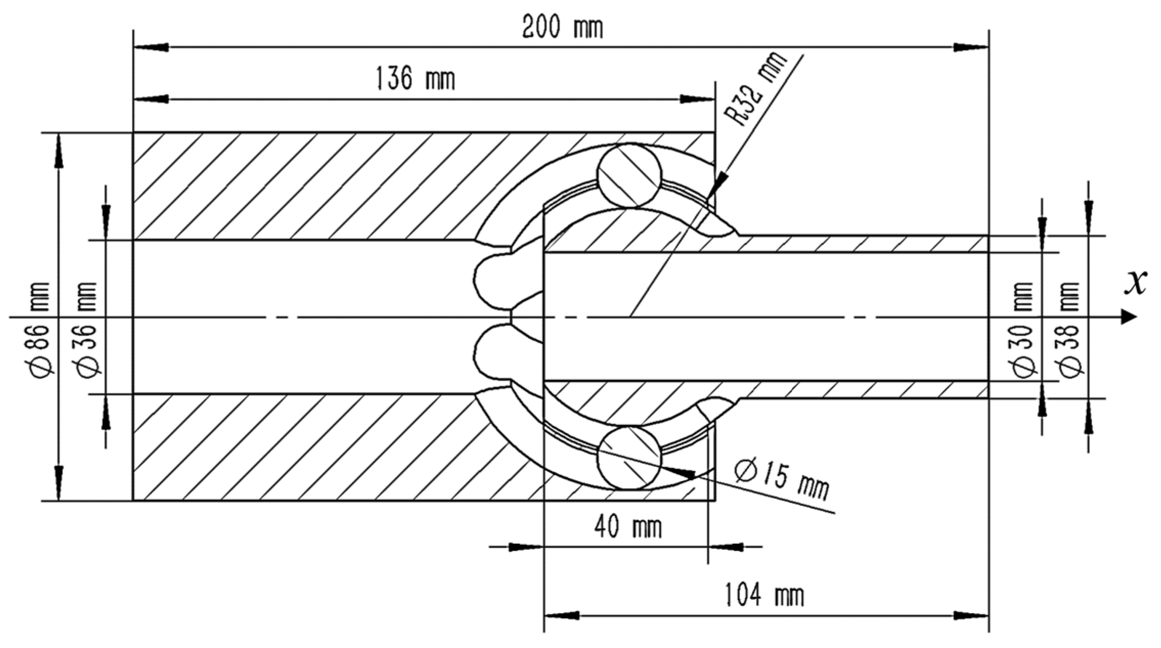
A new type of flexible drilling pipe is developed in this paper, and the structural parameters of the ball cage flexible joint are shown in Figure 3.
According to the geometric relationship between the components of the ball cage universal joint shown in Figure 4, the geometric equations of the contact points of the ball key and the inner race and the ball key and the outer race are established as follows.
In order to describe the internal motion of the ball cage universal joint accurately, the motion equations of the contact point between the ball key and the flexible drill pipe need to be established.
l b = ( l b , x l b , y l b , z ) = D C 1 { B 1 { A 1 ( 0 P C R b 0 ) } ( 0 δ sin β 2 0 ) }
l b i = ( l b i , x l b i , y l b i , z ) = D C 1 { B 1 { A 1 ( 0 r b cos θ b i r b sin θ b i ) ( 0 P C R b 0 ) } ( 0 δ sin β 2 0 ) }
l b o = ( l b o , x l b o , y l b o , z ) = D C 1 { B 1 { A 1 ( 0 r b cos θ b o r b sin θ b o ) ( 0 P C R b 0 ) } ( 0 δ sin β 2 0 ) }
where
A = ( cos ( γ ) sin ( γ ) 0 sin ( γ ) cos ( γ ) 0 0 0 1 ) , B = ( 1 0 0 0 cos ( φ ) sin ( φ ) 0 sin ( φ ) cos ( φ ) ) , C = ( cos ( β 2 ) sin ( β 2 ) 0 sin ( β 2 ) cos ( β 2 ) 0 0 0 1 ) , D = ( cos ( β ) sin ( β ) 0 sin ( β ) cos ( β ) 0 0 0 1 ) .
where β (°) is the working angle of the universal joint; γ (°) is the angle between the inner race pitch radius and the outer race pitch radius; δ (mm) is the distance between the center of the inner race pitch circle and the center of the outer race pitch circle; PCRb (mm) is the pitch radius of the ball set rotation center; rb (mm) is the diameter of the ball key; φ (°) is the rotation angle of the universal joint; θbi is the contact angle between the ball key and the outer race; θbo (°) is the contact angle between the ball key and the inner race; l b (mm) is the relative coordinate vector of the ball center; l b i (mm) is the coordinate vector of the contact point between the ball key and the inner race; l b o (mm) is the coordinate vector of the contact point between the ball key and the outer race.

2.2. Kinematic Equation of Flexible Drill Pipe

The flexible drill pipe is simplified to n hinged joints of length l. The geometric coordinates of the flexible drill pipe are established within the borehole structure, in which the curvature radius of the borehole is R. The point Oi is the mass center of the joint (its number is i), and Di is the geometric center of the ball head. XiYiZi is the local coordinate system established with Oi as the center, as shown in Figure 5.
The coordinates of the center of mass Oi (Xi, Yi, Zi) of the i-th flexible joint are
X i = l 2 sin φ i sin θ i + k = 1 i l sin φ k 1 sin θ k 1 Y i = l 2 sin φ i cos θ i + k = 1 i l sin φ k 1 cos θ k 1 Z i = l 2 l cos φ i + k = 1 i l cos φ k 1 }
where Xi, Yi, and Zi (mm) are the Cartesian coordinates of the flexible joint mass center; θi (°) is the angle between the joint and the y-axis in the xoy plane; and φi (°) is the angle between the joint and the z-axis.
The velocity of the mass center can be obtained by the derivative of Equation (4):
v x i = l 2 sin θ i cos φ i φ ˙ i + l 2 cos θ i sin φ i θ ˙ i + k = 1 i l sin θ k 1 cos φ k 1 φ ˙ k 1 + k = 1 i l cos θ k 1 sin φ k 1 θ ˙ k 1 v y i = l 2 cos θ i cos φ i φ ˙ i l 2 sin θ i sin φ i θ ˙ i + k = 1 i l cos θ k 1 cos φ k 1 φ ˙ k 1 k = 1 i l sin θ k 1 sin φ k 1 θ ˙ k 1 v z i = l 2 sin φ i φ ˙ i k = 1 i l sin φ k 1 φ ˙ k 1 }
where vxi, vyi, and vzi (mm/s) are the mass center velocity of the flexible joint; θi (°) is the angle between the joint and the y-axis in the xoy plane; φi (°) is the angle between the joint and the z-axis; θ ˙ i (°/s) is the angular velocity around the y-axis in the xoy plane of the joint; and φ ˙ i (°/s) is the angular velocity around the z-axis of the joint.

2.3. Dynamics Model of Contact

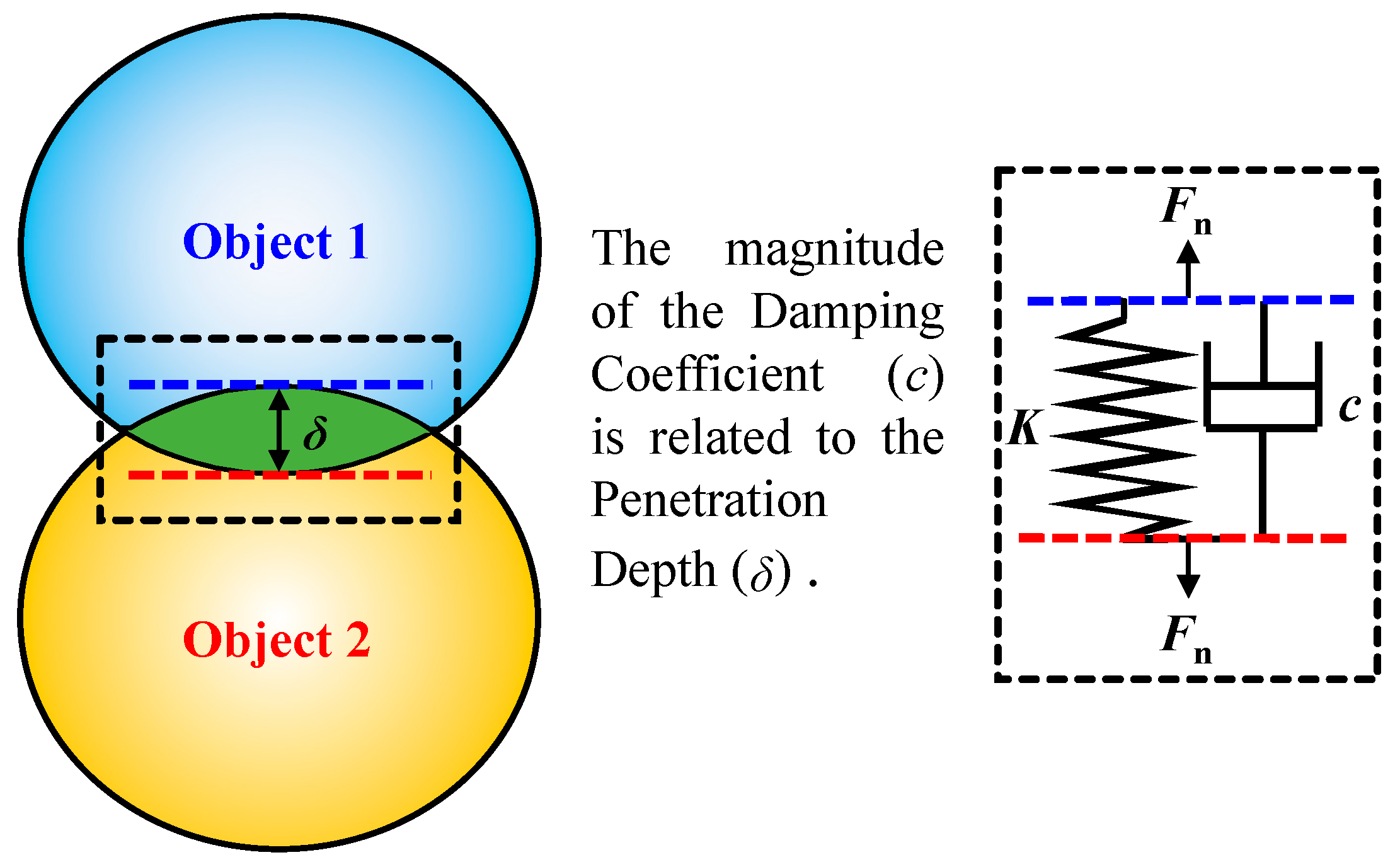
The selection of a suitable collision contact model is the key to the multi-body dynamics analysis of flexible drill pipes because multiple contact pairs exist in the ball cage flexible drill pipe structure. In this paper, the Lankarani–Nikravesh nonlinear collisional contact force model (as shown in Figure 6) based on the impact function is used to characterize the normal contact force [6], which is
F n = K δ n + c ( δ ) δ ˙
where K is the contact stiffness coefficient, which is 1 × 10⁵ N/mm; n is the elastic force index, which is 2.2; δ is the penetration depth of the contact surface, which is 0.1 mm; and c is the contact damping coefficient, which is 10.0 N. s/mm.
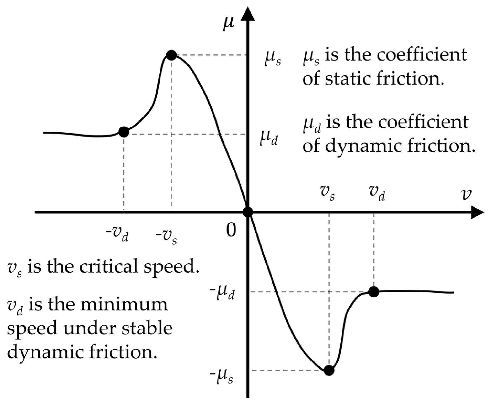
The tangential contact force also has a great influence on the motion of the flexible drill pipe, and a modified Coulomb friction model (as shown in Figure 7) is used in this paper to simulate the tangential friction at the contact point.
The function relationship among frictional force Ft, relative velocity v, and normal contact force Fn is
F t = { c d F n sign ( v ) step ( v , v s , μ s , v s , μ s ) | v | < v s c d F n sign ( v ) step ( | v | , v s , μ s , v d , μ d ) v s | v | v d c d F n sign ( v ) μ d | v | v d
where Ft, N; v, mm/s; Fn, N; cd is correction factor c d = ( v t v s ) / ( v d v s ) ; vt (mm/s) is the instantaneous tangential relative speed; μs is the coefficient of static friction between the flexible drill pipe and the guide tube, which is 0.3, and the coefficient of static friction inside the flexible drill pipe is 0.1 due to the presence of lubricant; μd is the coefficient of dynamic friction between the flexible drill pipe and the guide tube, which is 0.1, and the coefficient of dynamic friction inside the flexible drill pipe is 0.01; vs is the critical speed, which is 100 mm/s; and vd is the minimum speed under stable dynamic friction, which is 1000 mm/s.

3. Analysis of Flexible Drill Pipe Collision Contact

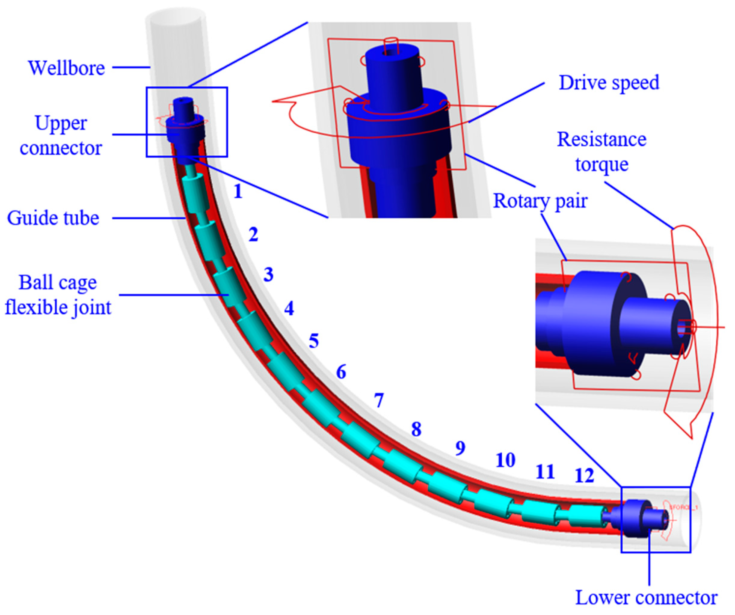
The ball cage flexible drill pipe is composed of an upper connector, a ball cage flexible joint, and a lower connector. The torsional driving force is transmitted to the flexible drill pipe through the upper connector and then to the drill bit through the lower joint. A multi-body dynamics model of the flexible drill pipe is established in the borehole with a curvature radius R, as shown in Figure 8. The borehole curvature radius R is 1.5 m, the flexible drill pipe consists of 12 flexible joints, and the geometric parameters of each component are shown in Table 1. The material of the guide pipe and flexible drill pipe in the model is 35CrMo, for which the density is 76.93 kg/m3, Young’s modulus is 210 GPa, and Poisson’s ratio is 0.3.
The guiding tube is restrained by fixed sub-constraints according to the structural characteristics and working conditions of the ball cage flexible joint. The rotating sub-constraint and driving speed are applied to the upper connector to simulate the guiding action of the guide tube and drilling torque; the rotating sub-constraint and resisting moment (1.8 kN.m) are applied to the lower connector to simulate the guiding action of the guide tube and drilling resistance; and the overall gravitational acceleration of the model is 9.8 m/s2.
The internal contact settings of each component of the ball cage flexible drill pipe are shown in Table 2.

3.1. Motion Trail of Flexible Joint

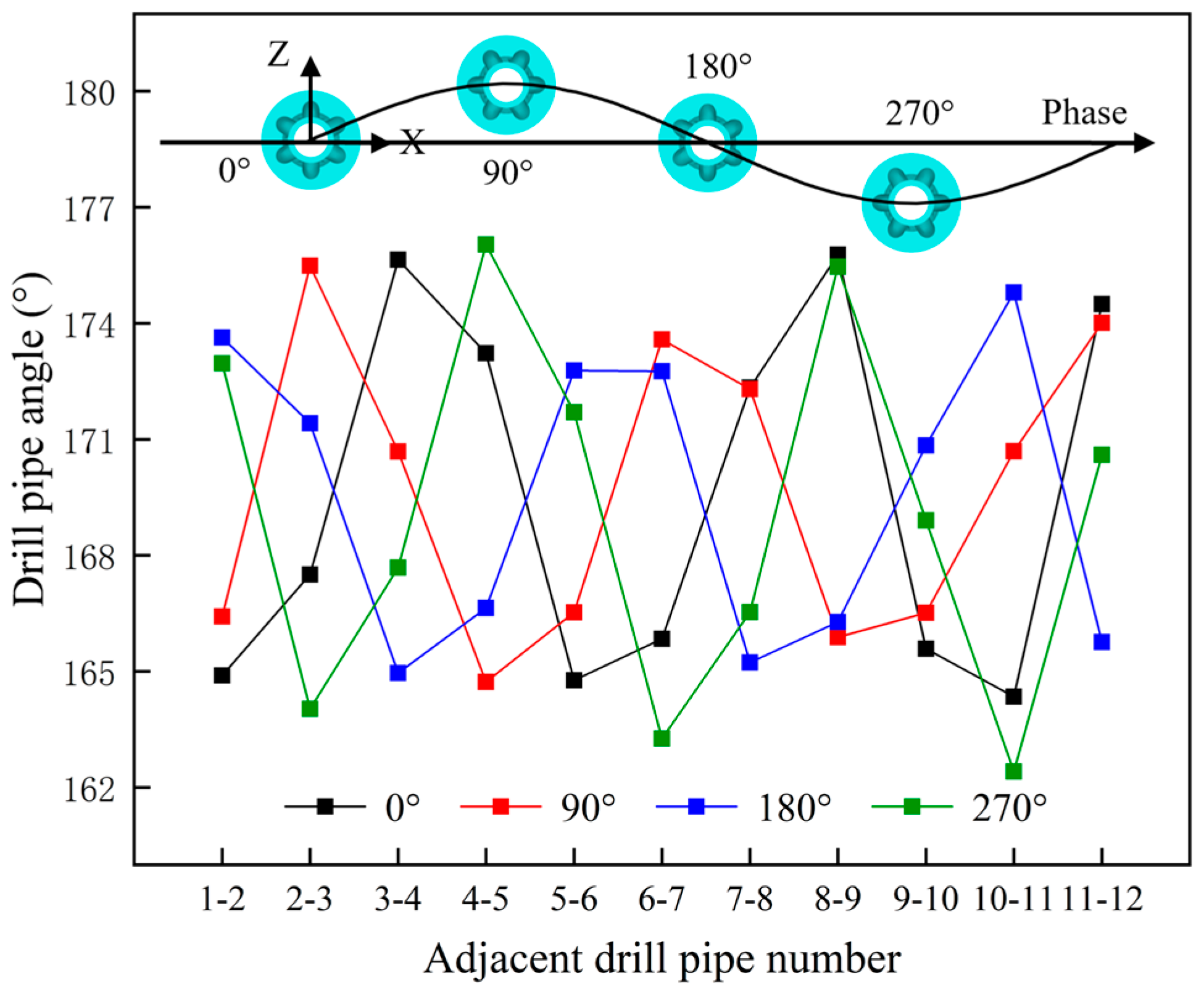
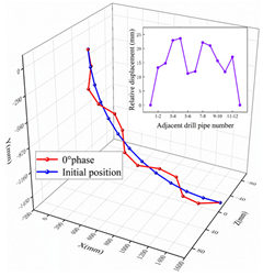
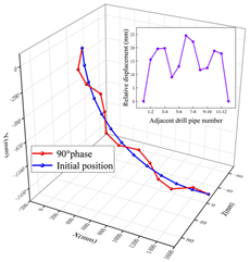
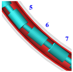
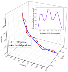
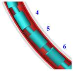
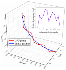
The multi-body motion state of the flexible drill pipe at different moments is obtained by applying a driving speed of 100 r/min to the upper connector, setting the simulation duration to 1.8 s, and setting the step size to 0.001 s. Four phase (0°, 90°, 180°, and 270°) moments in one cycle are selected after the flexible drill pipe enters the stable rotation state. Additionally, the motion behavior of the flexible joint in the guide tube is obtained. Table 3 shows the positions of the flexible drill pipe ball head and ball seat at the moments of phase 0°, 90°, 180°, and 270°, respectively. Figure 9 shows the angle of adjacent flexible joints.
According to Table 3 and Figure 9, the amplitude of movement and the relative angle of the rotation of the flexible drill pipe connected with the upper and lower connectors is small, while the nearer to the middle part, the larger the amplitude of movement is, which is because the upper and lower connectors are fixed in the center of mass under the support of the guide tube, which limits the movement of the joints at both ends; the change in the relative angle of rotation of the flexible joint is not large, so it can be considered that the influence of the self-weight of the flexible joint on the movement is small.

3.2. Analysis of the Contact between the Flexible Joint and the Guide Tube

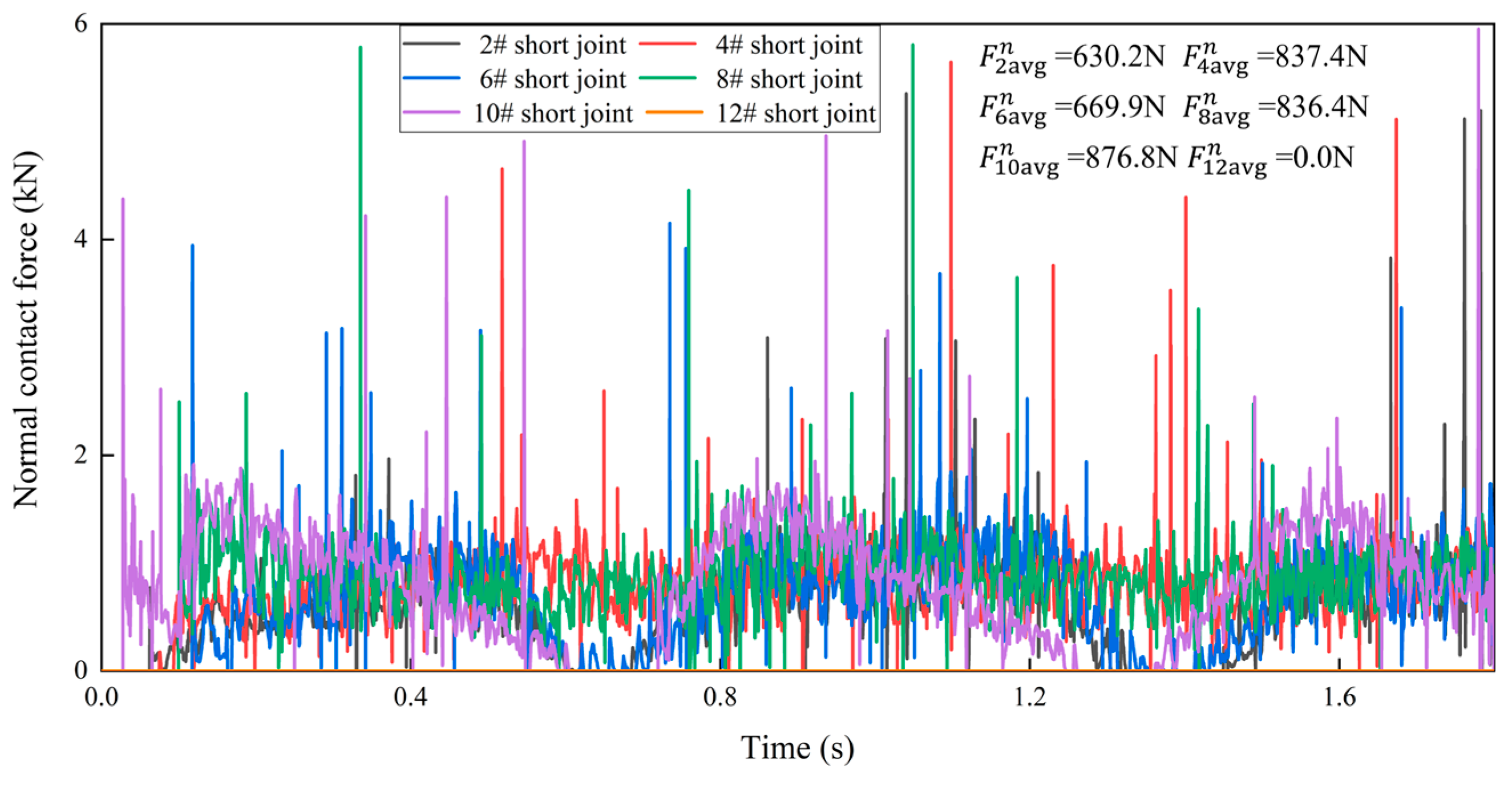
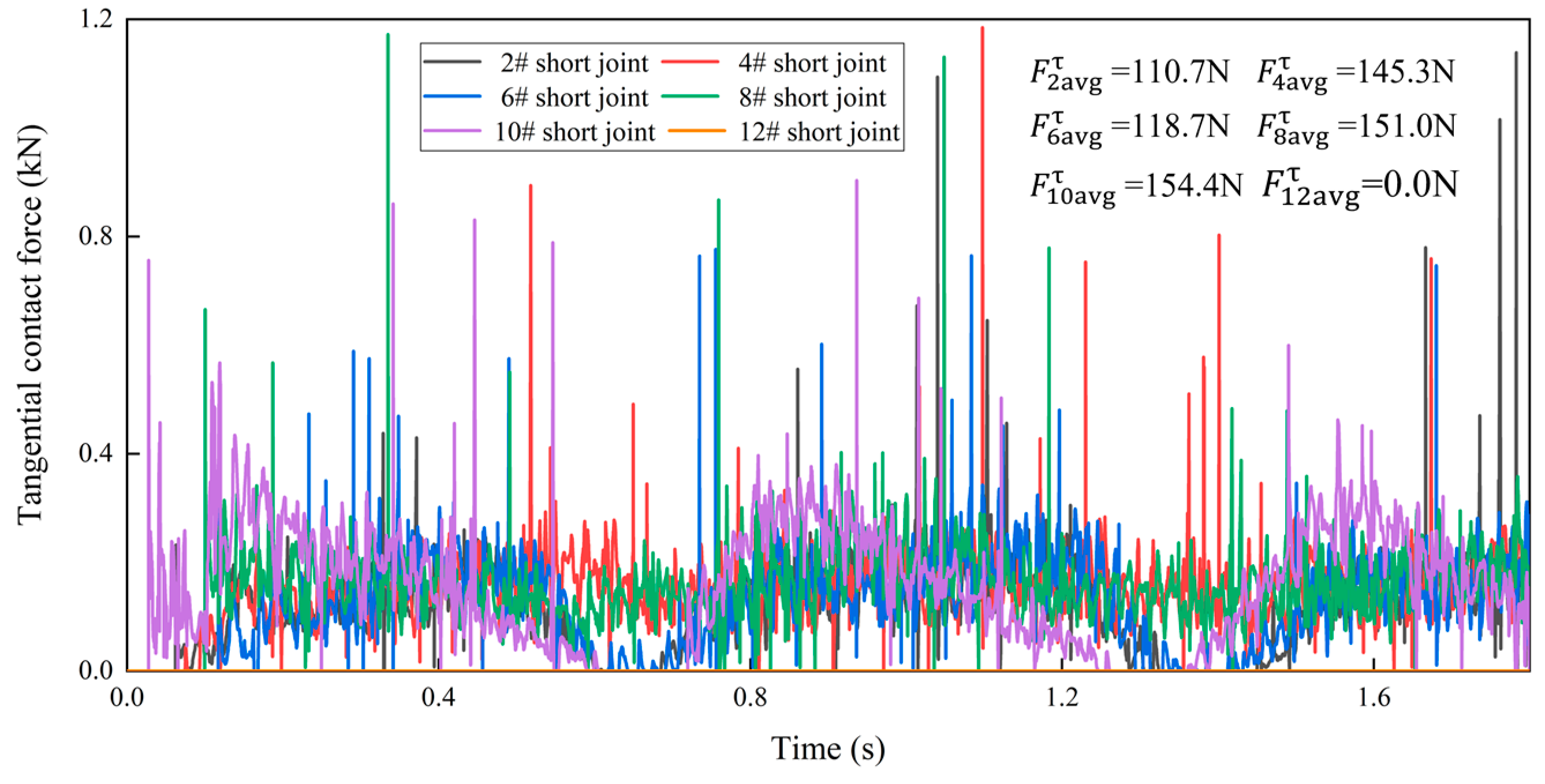
The flexible joint collides with the guide tube and makes frictional contact during the rotation. Five flexible joints (2#, 4#, 6#, 8#, and 10#) are selected from top to bottom, and their contact forces with the guide tube are analyzed; the evolution of the tangential and normal contact forces with time is shown in Figure 10 and Figure 11.
According to Figure 10 and Figure 11, the contact force of different flexible joints is in a state of fluctuation, and the average normal contact force of the flexible joint is 7.1 kN, which is much larger than the average tangential contact force of 1.4 kN, so the main contact of the flexible joint on the guide tube is normal impact force; flexible joint 10# (well slope angle is 75°) has the highest peak and average contact force on the guide tube, which are 5952.9 N and 876.8 N, respectively; and the average contact force between flexible joint 12# and the guide tube is 0 N.
This is because the centers of mass of the upper and lower connectors are fixed, the centripetal force is larger while the well slope angle is between 30° and 70° under the influence of the gravity of the flexible joint, and the contact force between the flexible joint and the guide tube is also larger.
The flexible joint in contact with the lower connector has a small rotation and does not make contact with the guide tube, so the average contact force is 0 N.

3.3. Analysis of Flexible Drill Pipe Internal Contact

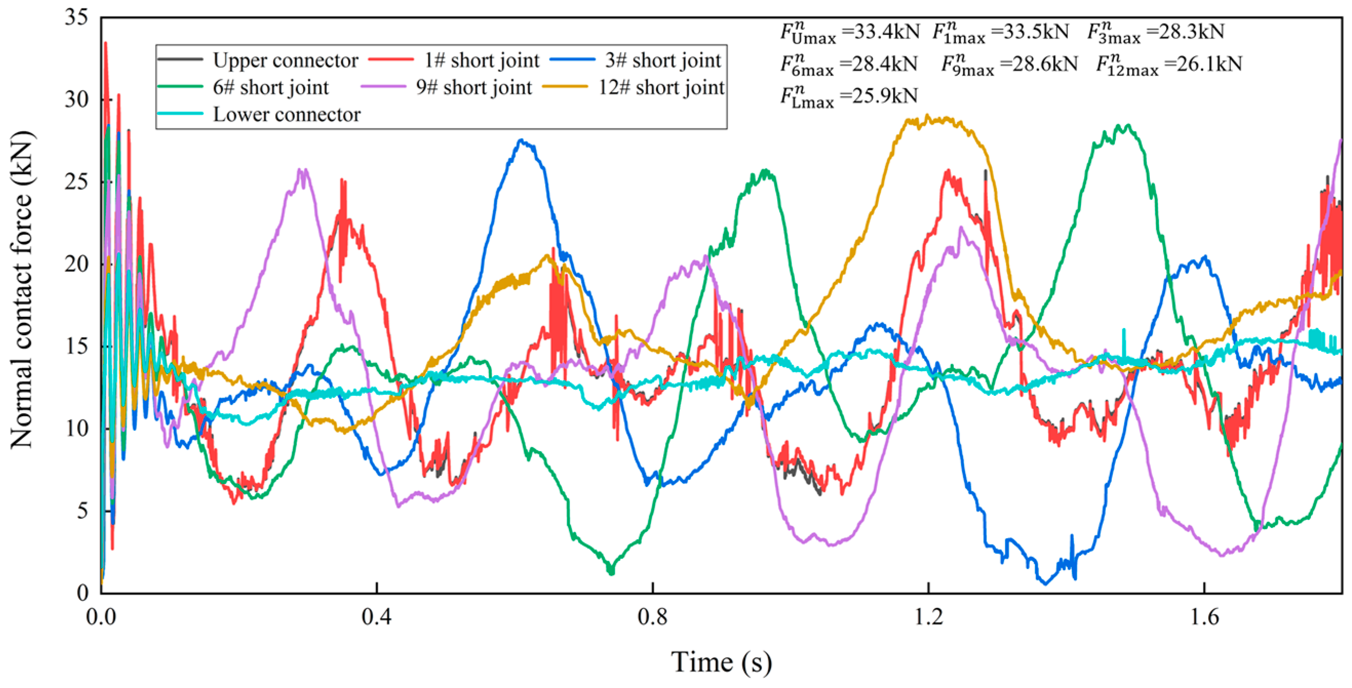
The maximum contact force between the ball seat and ball cage of the flexible drill pipe is 23.8 kN during the rotation, and the value between the ball cage and ball key is 5.8 kN, while the value between the ball seat and ball key is much larger than the above two values, which is 33.5 kN. Additionally, the contact force between the adjacent ball seat and ball head and the other components is approximately equal, so the contact analysis between the ball seat and the ball key is used to study the contact behavior inside the flexible drill pipe in this paper.
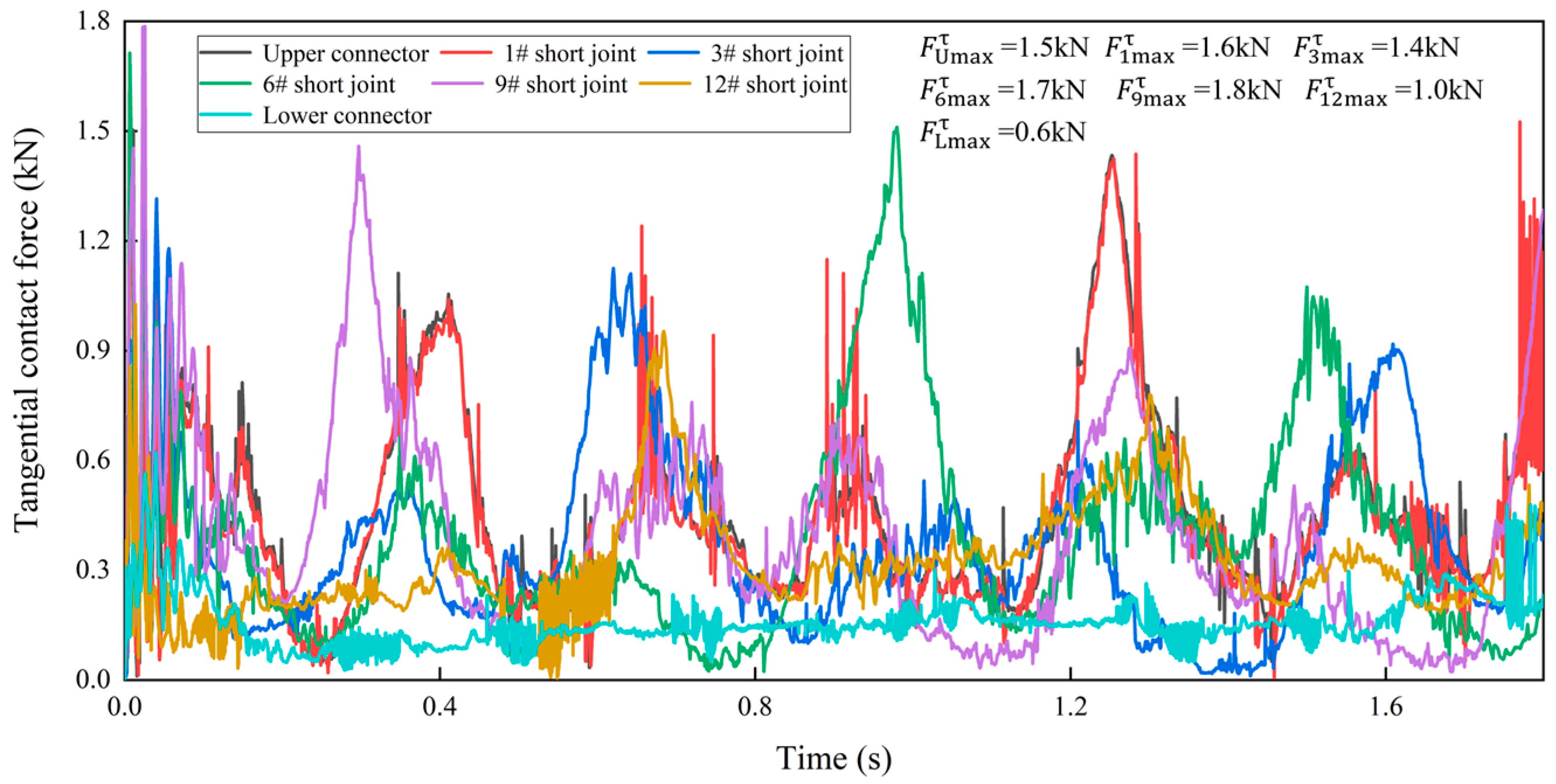
The contact forces between the different components of the flexible drill pipe and ball key are shown in Figure 12 and Figure 13. According to the figures, it can be obtained that the contact force between the different flexible joints and ball key changes periodically, and the maximum normal contact force is 33.5 kN, which is much larger than the maximum tangential contact force of 1.8 kN. This is due to the fact that the ball key contact is rolling friction and has the effect of lubricant, the friction coefficient is small, and the tangential contact force is smaller. The normal contact force of the acceleration stage is larger than the stable stage because of the inertia force; therefore, the peak normal contact force between the flexible joint and the ball key appears in the 1# flexible joint.

4. Parameter Influence

4.1. Influence of Borehole Curvature on the Length of Flexible Joint

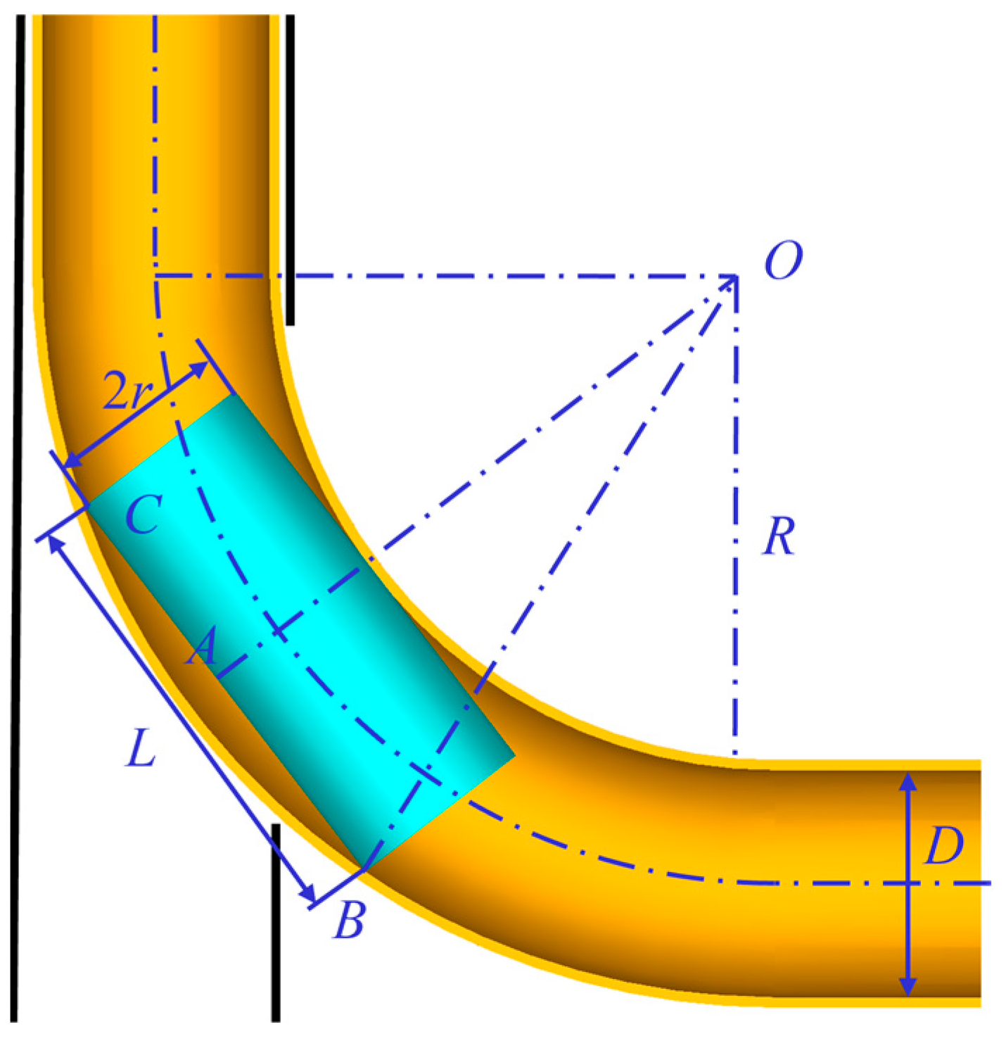
The length and radius of the flexible joint are determined by the borehole curvature. Each flexible joint is assumed to be rigid body, and a geometric relationship can be established, as shown in Figure 14. In the right triangle OAB, the geometric relationship between the length and radius of the flexible joint, the curvature radius of the borehole, and the inner diameter of the guide tube can be expressed as:
( L 2 ) 2 + ( R D 2 + 2 r ) 2 = ( R + D 2 ) 2
The length L of the flexible joint can be expressed as:
L = 2 2 R D 4 R r + 2 D r 4 r 2
where R (mm) is the curvature radius of the borehole; D (mm) is the inner diameter of the guide tube; and r (mm) is the radius of the flexible joint.
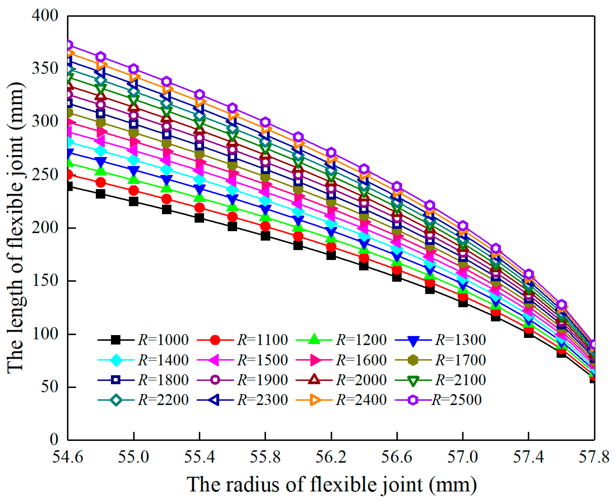
According to Equation (9), the mathematical relationship among the flexible joint length, radius, and curvature radius can be obtained, as shown in Figure 15. Additionally, this can be a criterion for the design of flexible joint length and radius to ensure the reliability of flexible joints in small curvature radius boreholes. In addition, the length of the flexible joint decreases as its radius increases, and a negative quadratic polynomial correlation is shown.

4.2. Influence of Borehole Curvature on Collision Contact Force

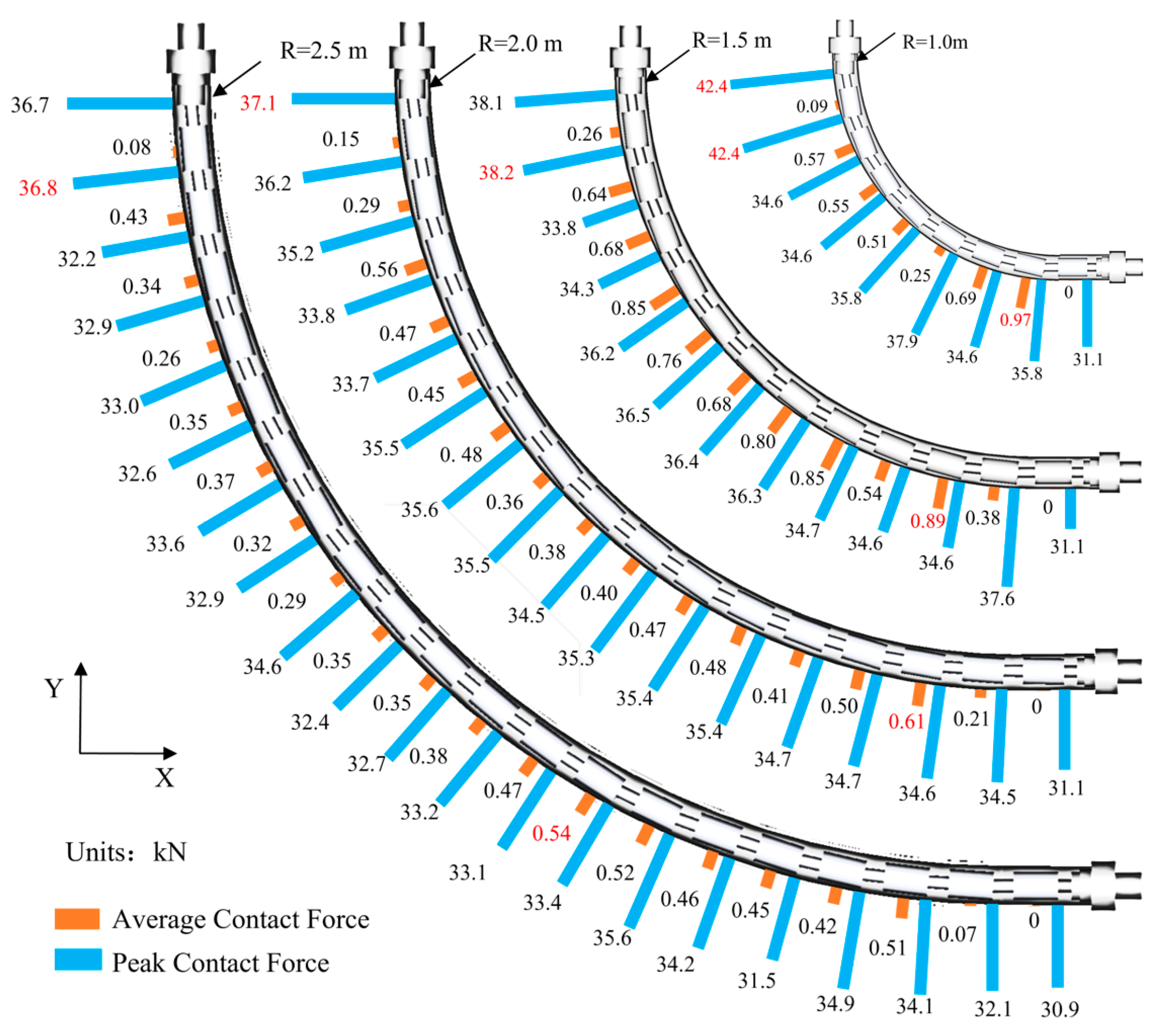
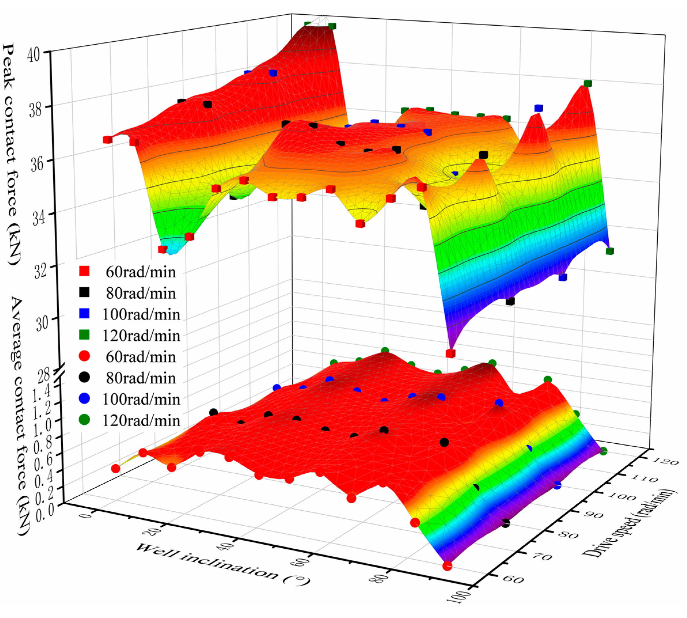
The average contact force between the flexible joint and the guide pipe and the peak contact force between the flexible drill pipe and ball key are obtained when the radius of borehole curvature gradually increases from 1.0 m to 2.5 m, as shown in Figure 16.
According to Figure 16, the maximum average contact force between the flexible drill pipe and the guide tube under different borehole radius conditions occurs at the well slope angle between 50° and 80°. The maximum average contact force is 0.97 kN, and the well slope angle is 78° when the borehole radius is 1.0 m. The maximum average contact force is 0.25 kN, and the well slope angle is 58° when the borehole radius is 2.5 m. Therefore, the extreme value of the average contact force between the flexible drill pipe and the guide tube gradually increases as the borehole radius decreases. The reason is that the smaller the borehole radius is, the larger the angle between adjacent flexible joints is, and the larger the rotational inertia of the flexible joints is, the greater the chance of collision between the flexible joints and the guide tube, and the greater the contact force will be.
The peak contact force between the flexible drill pipe and ball key under different borehole radii occurs at the upper joint head or 1# flexible joint, according to the results of the analysis in Figure 16. The peak contact force is 42.4 kN, and the borehole slope angles are 0° and 7.5° when the borehole radius is 1.0 m; the peak contact force is 36.8 kN, and the borehole slope angle is 4.5° when the borehole radius is 2.5 m. The angle between adjacent flexible joints and the inertial resistance will be larger, and the peak contact force between the flexible drill pipe and the ball key will gradually increase as the borehole radius becomes smaller.

4.3. Influence of Drive Speed

When the driving speed of the upper connector is 60 r/min, 80 r/min, 100 r/min, or 120 r/min, the average contact force between the flexible joint and the guide tube, and the peak contact force between the flexible joint and the ball key are analyzed, as shown in Figure 17.
The maximum value of the average contact force at different driving speeds occurs between 60° and 75° of well deviation. The maximum average contact force of the flexible drill pipe with a driving speed of 60 r/min is 0.79 kN, and the well inclination angle is 75°. The maximum average contact force of the flexible drill pipe with a driving speed of 120 r/min is 0.92 kN, and the well inclination angle is 60°. It can be seen that with the increase in driving speed, the maximum value of the average contact force between the flexible drill pipe and the guide tube gradually increases. As the driving speed increases, the collision between the flexible joint and the guide tube will be more intense, and the average contact force will also be greater.
The peak contact force of different drive speeds appears at the upper connector or 1# flexible joint. The peak contact force of the flexible drill pipe with a driving speed of 60 r/min is 36.7 kN, and the well inclination angles are 0° and 7.5°. The peak contact force of the flexible drill pipe with a driving speed of 120 r/min is 39.7 kN, and the well deviation angles are 0° and 7.5°. It can be seen that with the increase in driving speed, the peak contact force between the flexible drill pipe and the guide tube gradually increases. As the driving speed increases, the collision between the flexible joint and the guide tube intensifies, and greater contact force will also be generated between the flexible drill pipe and the ball key.
According to the simulation results, we can study the motion trajectory of the flexible drill pipe with different structural dimensions, driving pressures, and driving speeds; establish the relationship model between different parameters and the motion characteristics of flexible joint; and control the drilling trajectory by changing the control parameters to maintain the given drilling direction.

5. Conclusions

In order to propose a reference for the optimization of the flexible drill pipe structure, the kinematic behavior and the collision contact characteristics of the flexible joint were analyzed in this paper. The following conclusions were obtained:
(1)
The deformation of the ball-cage flexible drill pipe shows a “folded” shape compared to the initial form, and the nearer to the middle, the greater the degree of “fold”.
(2)
The contact force between the flexible drill pipe and the guide tube is randomly distributed, and the change in collision contact force is closely related to the borehole curvature radius. When the borehole curvature radius decreases, the contact force increases significantly, and the drilling load loss is very high. The contact force of different flexible joints is in a fluctuation state, and the normal contact force of flexible joints is much larger than the tangential contact force.
(3)
The geometric relationship among borehole curvature, flexible joint length, and radius is derived, which provides criteria for the flexible joint size design to ensure the reliability of a flexible drill pipe in large curvature boreholes.
(4)
The driving speed is positively related to the average contact force between the flexible drill pipe and the guide tube and the peak contact force between the flexible drill pipe and the ball key.
The results can provide ideas for the design and wear analysis of flexible drilling tools used in ultra-short radii. However, the proposed method is limited to rigid body dynamics. More new theoretical findings related to rigid-flexible multi-body dynamics should be considered in future studies.

Author Contributions

Writing—original draft, X.Z., Y.X. (Yingpeng Xu), C.M., W.Z., G.Y. and B.Z.; writing—review and editing, X.Z., Y.X. (Yuanbo Xia), G.Y. and B.Z. All authors have read and agreed to the published version of the manuscript.

Funding

This work was supported by the National Key Research and Development Program of China (no. 2019YFC1509204) and the Independent Innovation Research Program of China University of Petroleum (East China) (no. 27RA2215005).

Data Availability Statement

The data presented in this study are available in this article.

Conflicts of Interest

The authors declare no conflict of interest.

References

  1. Cao, X.; Zhang, C.; Zhang, C. A Kind of Ultra-Short Radius Radial Horizontal Drilling and Completion Tool and Drilling and Completion Technology. China Patent CN100567695C, 9 December 2009. [Google Scholar]
  2. Moustafa, E.B.; Elsheikh, A. Predicting Characteristics of Dissimilar Laser Welded Polymeric Joints Using a Multi-Layer Perceptrons Model Coupled with Archimedes Optimizer. Polymers 2023, 15, 233. [Google Scholar] [CrossRef]
  3. Khoshaim, A.B.; Moustafa, E.B.; Bafakeeh, O.T.; Elsheikh, A.H. An Optimized Multilayer Perceptrons Model Using GreyWolf Optimizer to Predict Mechanical and Microstructural Properties of Friction Stir Processed Aluminum Alloy Reinforced by Nanoparticles. Coatings 2021, 11, 1476. [Google Scholar] [CrossRef]
  4. Elsheikh, A. Bistable Morphing Composites for Energy-Harvesting Applications. Polymers 2022, 14, 1893. [Google Scholar] [CrossRef]
  5. Elsheikh, A.H.; El-Said, E.M.; Abd Elaziz, M.; Fujii, M.; El-Tahan, H.R. Water distillation tower: Experimental investigation, economic assessment, and performance prediction using optimized machine-learning model. J. Clean. Prod. 2023, 388, 135896. [Google Scholar] [CrossRef]
  6. Luo, M.; Xu, T.; Jiang, J.; Chi, X.; Wang, J.; Xue, S. Two-layer Contact Nonlinear Mechanical Analysis of Flexible Drilling Tool in The Wellbore. Comput. Model. Eng. Sci. 2020, 123, 75–100. [Google Scholar] [CrossRef]
  7. Zhu, X.; Xu, Y.; Zhou, W.; Ye, G.; Zhou, B. Research on Parameter Design Method and Motion Characteristics of a Ball Cage Flexible Joint. Energies 2022, 15, 7591. [Google Scholar] [CrossRef]
  8. Bai, Z.F. Research on Dynamic Characteristic of Mechanism with Joint Clearance; Harbin Institute of Technology: Harbin, China, 2011. [Google Scholar]
  9. Hunt, K.H.; Crossley, F.R. Coefficient of restitution interpreted as damping in vibroimpact. J. Appl. Mech. 1975, 42, 440–445. [Google Scholar] [CrossRef]
  10. Lankarani, H.M.; Nikravesh, P.E. A contact force model with hysteresis damping for impact analysis of multibody systems. J. Mech. Des. 1990, 112, 369–376. [Google Scholar] [CrossRef]
  11. Luka, S.; Janko, S.; Miha, B. A validated model for a pin-slot clearance joint. Nonlinear Dyn. 2017, 88, 131–143. [Google Scholar] [CrossRef]
  12. Alexander, G.; Bernd, S. Modeling planar slider-crank mechanisms with clearance joints in recurdyn. Multibody Syst. Dyn. 2014, 31, 127–145. [Google Scholar] [CrossRef]
  13. Bai, Z.F.; Zhao, Y. Dynamics modeling and quantification analysis of multibody systems including revolute clearance joints. Precis. Eng. 2012, 36, 554–567. [Google Scholar] [CrossRef]
  14. Wang, X.P.; Liu, G.; Ma, S.J. Dynamic analysis of planar mechanical systems with clearance joints using a new nonlinear contact force model. J. Mech. Sci. Technol. 2016, 30, 1537–1545. [Google Scholar] [CrossRef]
  15. Manzoli, O.L.; Tosati, M.; Rodrigues, E.A.; Bitencourt, L.A. Computational modeling of 2D frictional contact problems based on the use of coupling finite elements and combined contact/friction damage constitutive model. Finite Elem. Anal. Des. 2022, 199, 103658. [Google Scholar] [CrossRef]
  16. Yue, J.; Liu, G.-R.; Li, M.; Niu, R. A cell-based smoothed finite element method for multi-body contact analysis using linear complementarity formulation. Int. J. Solids Struct. 2018, 141, 110–126. [Google Scholar] [CrossRef]
  17. Kimata, K.; Nagatani, H.; Imoto, M.; Kohara, T. Numerical analyses and experiments on the characteristics of ball-type constant-velocity joints. JSME Int. J. 2004, 47, 746–754. [Google Scholar] [CrossRef] [Green Version]
  18. Wang, G.; Liu, H.; Deng, P.; Yin, K.; Zhang, G. Dynamic analysis of 4-SPS/CU parallel mechanism considering three-dimensional wear of spherical joint with clearance. J. Tribol. 2017, 139, 021608. [Google Scholar] [CrossRef]
  19. Marques, F.; Flores, P.; Claro, J.C.P.; Lankarani, H.M. Modeling and analysis of friction including rolling effects in multibody dynamics: A review. Multibody Syst. Dyn. 2019, 45, 223–244. [Google Scholar] [CrossRef]
  20. Chen, X.; Hu, Q.; Xu, Z.; Zhu, C. Numerical modeling and dynamic characteristics study of coupling vibration of multistage face gearsplanetary transmission. Mech. Sci. 2019, 10, 475–495. [Google Scholar] [CrossRef]
  21. Onesmus, M.; John, K.; Bernard, I. Numerical study of parametric effects on the dynamic response of planar multi-body systems with differently located frictionless revolute clearance joints. Mech. Mach. Theory 2012, 53, 30–49. [Google Scholar] [CrossRef]
  22. Luo, M.; Xu, T.; Wang, J.; Li, Q.Z.; Zhang, J.H. Contact nonlinear finite element analysis of controllable universal joint flexible slender in tube. J. China Univ. Pet. (Ed. Nat. Sci.) 2019, 43, 75–81. [Google Scholar] [CrossRef]
  23. Luo, G.; Zou, L.; Huang, Y.; Gong, M. Study on material removal and surface quality in titanium alloy grinding with alumina hollow-sphere abrasive belt. China Mech. Eng. 2020, 15, 1798–1807. [Google Scholar] [CrossRef]
  24. Liu, Q.; Tong, K.; Zhu, G.-C.; Tan, Y.; Zhang, J.; Xu, X.; Li, X.; Song, S.-Y. Investigation of fracture causes of the titanium alloy drill pipe in ultra-short radius horizontal well drilling. Eng. Fail. Anal. 2022, 140, 106516. [Google Scholar] [CrossRef]
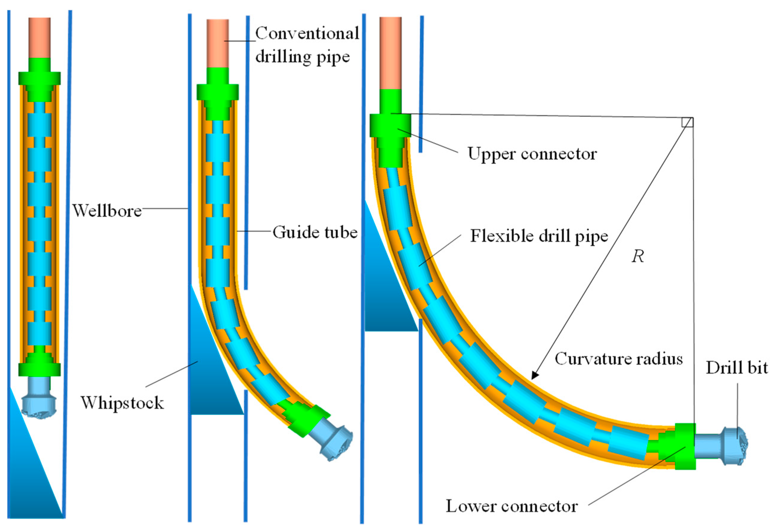
Figure 1. Structure of flexible drill tool.
Machines 11 00357 g001
Figure 2. Structure of ball cage flexible joint.
Machines 11 00357 g002
Figure 3. Structural parameters of ball cage flexible joint.
Machines 11 00357 g003
Figure 4. Geometric relationship of components in the ball cage universal joint.
Machines 11 00357 g004
Figure 5. Local coordinate system of the universal joint.
Machines 11 00357 g005
Figure 6. Normal contact force model.
Machines 11 00357 g006
Figure 7. Coulomb friction model.
Machines 11 00357 g007
Figure 8. Multi-body dynamics model flexible drill pipe.
Machines 11 00357 g008
Figure 9. Angle between adjacent flexible joints.
Machines 11 00357 g009
Figure 10. Variation curve of normal contact force between flexible drill pipe and guide tube.
Machines 11 00357 g010
Figure 11. Variation curve of tangential contact force between flexible drill pipe and guide tube.
Machines 11 00357 g011
Figure 12. Normal contact force between upper and lower connectors and ball key, and 1#, 3#, 6#, 9#, 12# flexible drill pipe and ball key.
Machines 11 00357 g012
Figure 13. Tangential contact force between upper and lower connectors and ball key, and 1#, 3#, 6#, 9#, 12# flexible drill pipe and ball key.
Machines 11 00357 g013
Figure 14. The dimensional relationship of the flexible joint.
Machines 11 00357 g014
Figure 15. Variation curve of length of flexible joint with different radii.
Machines 11 00357 g015
Figure 16. Distribution of flexible drill pipe contact force with different borehole radii.
Machines 11 00357 g016
Figure 17. Contact force change curve of flexible drill pipe at different driving speeds.
Machines 11 00357 g017
Table 1. Geometric parameters of the model.
NumberNameExternal Diameter/mmInner Diameter/mmLength/mm
1Wellbore-124-
2Guide tube121116750 π
3Upper/lower connector12230200
4Flexible joint8630200
5Ball head6230104
6Ball cage646240
7Ball key15--
8Ball seat8664136
Table 2. Contact relationship of each component of flexible drill pipe.
ComponentUpper ConnectorBall CageFlexible Joint
Ball cageCollision friction contact--
Ball head Collision friction contact
Ball keyCollision friction contactCollision friction contact
Lower connector Collision friction contact
Guide tube Collision friction contact
Table 3. Flexible joint geometry at different moments.
Position and Relative Displacement of
Flexible Drill Pipe
Shape of Flexible Joint
Machines 11 00357 i001Machines 11 00357 i002
Joint number with maximum deformation Adjacent included angleRange of motion
4#173.2°23.6 mm
90°Machines 11 00357 i003Machines 11 00357 i004
Joint number with maximum deformation Adjacent included angleRange of motion
6#173.6°24.5 mm
180°Machines 11 00357 i005Machines 11 00357 i006
Joint number with maximum deformation Adjacent included angleRange of motion
5#172.8°25.0 mm
270°Machines 11 00357 i007Machines 11 00357 i008
Joint number with maximum deformation Adjacent included angleRange of motion
4#25.3 mm176.0°
Disclaimer/Publisher’s Note: The statements, opinions and data contained in all publications are solely those of the individual author(s) and contributor(s) and not of MDPI and/or the editor(s). MDPI and/or the editor(s) disclaim responsibility for any injury to people or property resulting from any ideas, methods, instructions or products referred to in the content.