Article

Analysis of the Causes of Damage to the Stabilisation Actuator of the Cap Piece of the Powered Roof Supports and a Proposal to Reduce the Effects

1
Center of Hydraulics DOH Ltd., ul. Konstytucji 147, 41-906 Bytom, Poland
2
Polska Grupa Górnicza S.A., ul. Powstańców 30, 40-039 Katowice, Poland
Machines 2023, 11(2), 194; https://doi.org/10.3390/machines11020194
Submission received: 21 December 2022 / Revised: 23 January 2023 / Accepted: 24 January 2023 / Published: 1 February 2023
(This article belongs to the Section Automation and Control Systems)

Abstract

:
The mining and geological conditions in which coal mining is carried out are highly variable, which results in dynamic rock manifestations. These include rock mass dynamic failure (seismicity), causing dynamic impacts and also quasi-static rock movements that do not result in seismicity but increases pressure in the powered roof support. The paper analyses the resulting damage to the stabilisation actuator of the cap piece. The analysis was carried out based on the research results conducted in real conditions (a mining longwall). This research study aims to obtain information about the pressure created in hydraulic actuators. Exceeding the design pressure limits caused damage to the bolt holes of the cap piece actuator. The pressure in the sub-piston space of the hydraulic prop was also analysed. The previous research conducted on mechanically powered roof supports focused mainly on bench tests. The results of the analysis carried out under real testing conditions currently comprise the starting point for the development of a new method to reduce adverse effects. Under the mining and geological conditions where the research was carried out, a high load on the roof’s side was under the load applied directly on the powered roof support. The load of the test’s results identified problems related to the safety valve in the sub-piston space of the actuators as it did not reach its opening time during the build up of the load.

1. Introduction

The development of operational and environmental safety systems in global coal longwall mining has been described previously in the author’s work [1]. This was based on the influence of mining factors using mathematical modelling, and the use of an algorithm was proposed. This allowed the prediction of the probable behaviour of the impact of mining factors. A bench study on the development of mechanical structure was described in the following paper [2]. They obtained the design of a prototype of the longwall support intended for energy recovery. In the coal mining process, emphasis is currently placed on the development of powered roof support structure in terms of new technical solutions. This is carried out in order to be innovative and to meet the basic condition of improving safety for difficult working conditions. Such a proposal was made by the authors in a publication [3]. Continuous improvements in mechanical support design for deteriorating conditions are currently one of the most topical issues [4]. Powered roof supports should be multifunctional, which was explained in the research paper [5]. However, each powered roof support should be assessed before using it for underground mining [6]. The above-cited works of the author currently represent the global direction of the development of powered roof supports.
Global underground coal mining, related to underground coal mining or open pit mining for other raw materials [7,8,9], seeks newer, safer, and cost-effective technical solutions [10,11,12]. To develop new technical solutions [13,14,15,16], conducting scientific research is necessary [17,18,19]. Scientific research for underground mining [20,21,22] can be divided into three research categories The first category is a simulation study [23,24,25,26] used to confirm the validity of an adopted concept. The second category consists of site tests [27,28,29]. Research on the prototype was carried out [30,31,32] to confirm its construction assumptions. The third category comprises research conducted for in situ conditions [33,34,35,36]. Positive in situ testing results obtained from the third research category allow assessing the usefulness of the developed technology [37,38,39,40].
However, which research zone is the most important is not specified in the literature [41,42]. Based on the review of publications on innovative [43] solutions, it can be concluded that research on real conditions is the most important [44] and includes two research categories. The first category comprises in situ research confirming the adoption of the concept and validating adopted assumptions [45,46]. The second category comprises conducting research in order to learn the causes of damage behaviour. This may include the aim of developing a new solution or proposing changes [47]. This paper focusses on the second category of research in the third research zone, which is research in real conditions.
In a wall complex, basic machines are a combine mining machine and a scraper conveyor [48]. The purpose of the combine mining machine is to cut coal, while the conveyor’s role is to transport the spoil. On the other hand, the powered roof support is needed to secure coal exploitation, including machinery and equipment. The mechanically powered roof support also protects working people. The role of the powered roof support in the complex is of the greatest importance [49]. The role of the powered roof support in the complex contributes to a high degree of safety [50]. This paper considers in situ test conditions to learn the damaging causes for the powered roof support actuator.
The construction of the powered roof support (see Figure 1) comprises a lemniscate mechanism (1). The base of the powered roof support is the stringer (2), in which the hydraulic props (3) are mounted. To move the conveyor and attach the powered roof support, we use a sliding system (4) with the actuator. This solution cooperates with a mechanical stringer that is mounted by a lift on a bolt connecting the stringers. The main element of the sliding system is the beam fixed between the stringer and the conveyor. The basic assembly for securing the working zone and the passageway is the cap piece (5). It pivotally attaches to the shield (6) with bolts. The cap piece is supported by two hydraulic props and is stabilised in the desired position by the cap piece’s support actuator (7).
All movements of the powered roof support are carried out by hydraulic controls [51]. The pressure on the powered roof support is controlled by the safety valves of the valve block located on the cylinders of the prop. The cycle of the operation of the powered roof support begins in the offset state. The conveyor is then extended to an extreme position at the face of the wall. The harvester in this position enables the cut. Immediately twice after the harvester passes, the section of the powered roof support is attached to the conveyor. After the harvester has travelled a sufficient distance, the retraction actuator switches to a conveyor-pushing position [52,53,54].
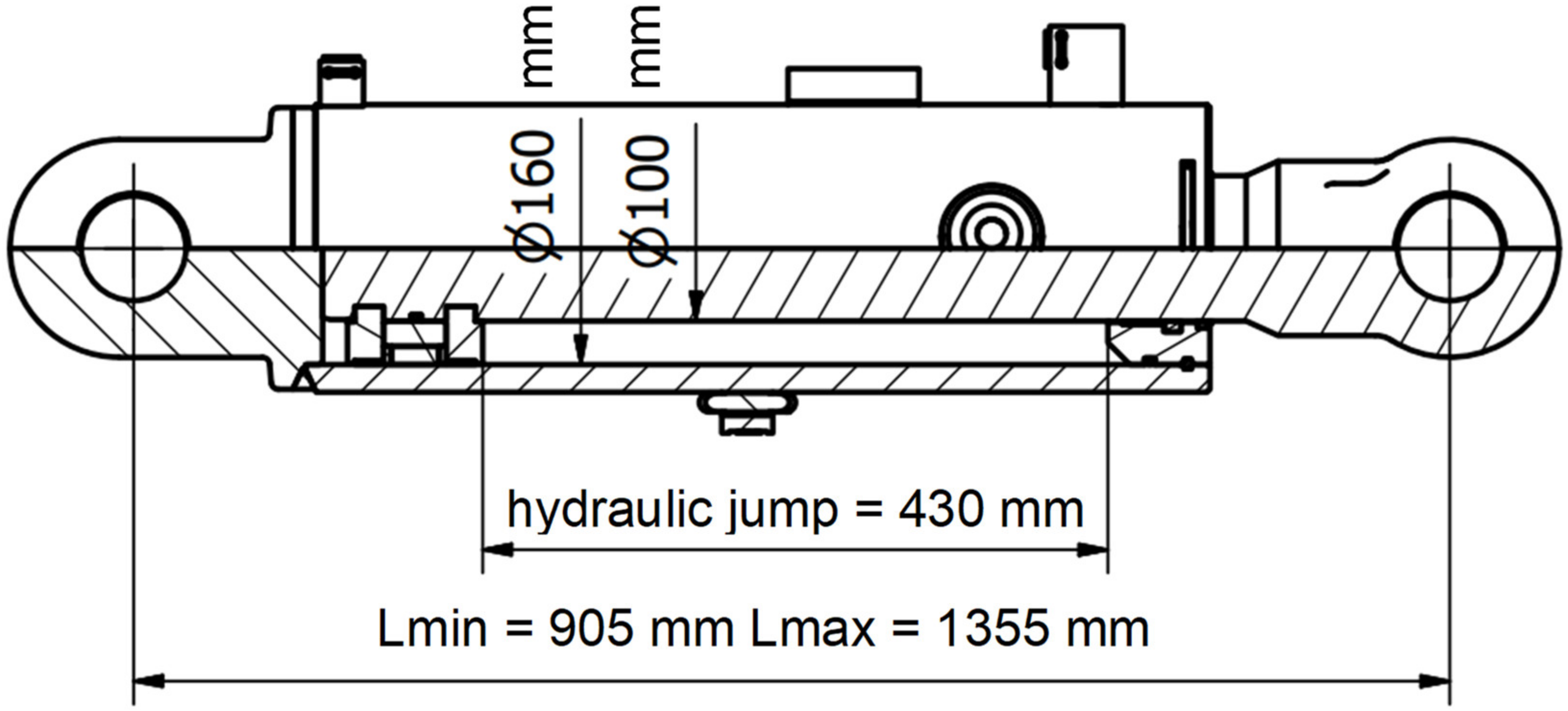
The subject of the research analysis is the cap piece’s support actuator (see Figure 2). It is used to set the angle of the cap piece relative to the shield and is characterised by bilateral action, pressing the front of the cap piece to the roof. This actuator is connected by a piston rod with a shield and a cylinder with the cap piece. Its task is to stabilise the mutual position of the cap piece and the shield while ensuring the stability of the powered roof support in the resting mode (i.e., unloaded). The cap piece’s support actuator consists of a piston and a cylinder with bolt holes for fixing the cap piece and the shield. Both working areas are protected by safety valves set at an opening pressure of 39 MPa.
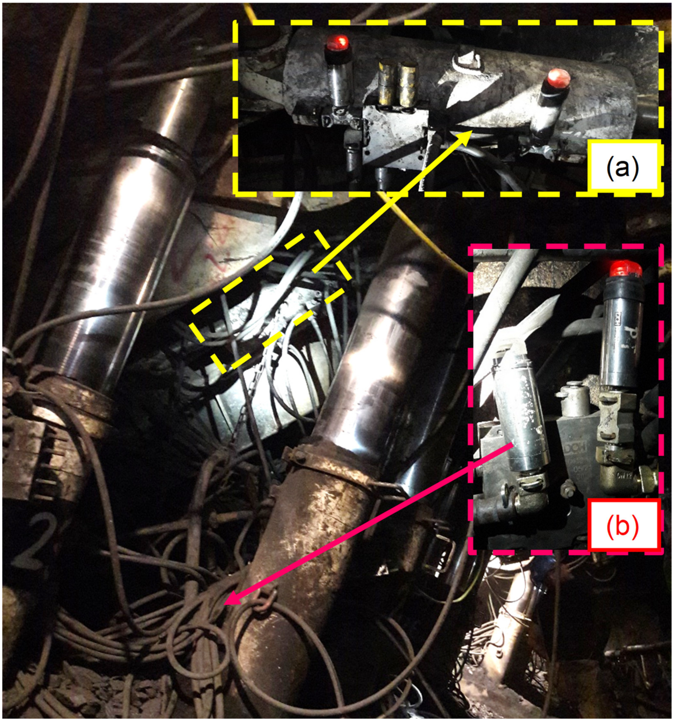
The observations were carried out along the mining longwall to investigate frequent damage to the power hydraulics, which prompted the investigation of the phenomenon in which the floor support actuator fails. For this purpose, measurements of the pressure generated in the cylinder of the canopy support caused by the violent impact of the rock mass began. Therefore, the purpose of this study is to obtain information about the pressure generated; for this purpose, a measuring and recording system was installed. This research analysis aims to present research findings and an effective engineering approach.

2. Materials and Methods

The cap piece’s support is used in the powered roof supports and spreads between the ceiling (5) and the shield (6) (see Figure 1). The location of the cap piece’s support in the powered roof support is shown in Figure 1. The over-piston space operates when the powered roof support is clamped, and the sub-piston space operates when the powered roof support raises. The basic technical data of the analysed support are presented in Table 1. The cap piece’s support is a double-acting actuator in which the over-piston space has been enlarged (Figure 2). For the proper operation of the powered roof support, the over-piston and under-piston forces are required to be similar:
PT = PN, N
  • where
  • PN—over-piston operation of the cap piece’s support;
  • PT—sub-piston operation of the cap piece’s support.
PrpSpPNSn, N
  • where
  • Prp—sub-piston working pressure, MPa;
  • Sp = Π 4 D2—sub-piston working surface, m2;
  • Prn—over-piston working pressure, MPa;
  • Sn = Π 4 (D2d2)—over-piston working surface, m2;
  • D—cylinder’s diameter, m;
  • d—piston rod’s diameter, m.
The formulae above show that the operating values of the pressure in the sub-piston and over-piston spaces are different. The clamping speed of the support is several times lower than the clamping speed of the hydraulic props and is a consequence of its location in the powered roof support. The conditions mentioned above significantly impact the selection of support protections.
The cap piece’s support is not resistant to dynamic loads due to the small column of liquid under the piston. There are particular difficult working conditions that occur in the over-piston space. For the proper operation of the powered roof support when there is a risk of rock mass shocks, the protections against dynamic overloads should be properly selected. This has a significant impact on the failure-free operation of the cap piece’s support, as well as the bolt’s connections.

3. Results

The behavior of rocks in the vicinity of a longwall mining pit, especially the roof rocks, depends on the formation of the rock mass. It is also influenced by the depth of the mined seam. Under given mining conditions, the behavior of the rock, and especially the extent to which changes occur, depends on the technology used to select the seam. The behavior of the rocks is influenced by the speed of the progress of the runout and the length of time the rocks remain unprotected after being shielded. The behavior of the rock also depends on the impact on the exposed casing protecting the longwall workings. The behavior of rock in the excavation surroundings proceeds differently in the start-up stage of a longwall mining operation and in the stage of steady-state excavation. As the longwall starts up, conditions and factors affecting the behavior of the rock surrounding the forming pit change as the longwall progresses. The effect of these factors intensifies successively with an increase in the distance of the front face of the selected deposit from the line of its initial location. The commissioning of the wall ends as a result of the formation of the base floor [43]. The behavior of the floor rocks significantly affected the damage shown in Figure 3.
The task of the powered roof support is to ensure that coal is safely and undisturbed by the rock mass from the mining pit. Meeting these requirements can be done with the correct selection of it, taking into account mining and geological conditions and parameters of the longwall. The selection of the powered roof support should be preceded by a thorough understanding of geological-mining conditions to determine the class of the roof and the compressive strength of the bedrock. The powered roof support influences the behavior of an excavation (so-called roof steering) by acting on it with an appropriate force called support. There are three types of support in the different phases of the powered roof support lining cycle [44].
The first support that a set of mechanized longwall lining develops at the moment of spreading is the initial support (PW). It results from the current supply pressure in the supply line. The second is the nominal support (PN), which is the maximum support that a set of powered roof support can achieve under static loading. It depends on the opening pressure of the safety valves in the support system of the hydraulic supports of the powered roof support set. The third is working support (PR). This is the bearing capacity that of the powered roof support set is currently achieving under the rock mass pressure. Its value is between the initial support and the working support. Therefore, for the proper operation of the excavation, the powered roof support must have the appropriate working support specified. Which is largely influenced by the height of the pit and the type of roof rock. It is also important to have a proper relationship between the initial support and the nominal support [44].
  • PW = PR = PN (1)
  • where
  • PW—initial suport,
  • PR—operating support,
  • PN—nominal support capacity.
If the initial support (PW) is too high, it may happen that the working support (PR) required for proper guidance of the mine workings is less than the initial support (PW). Damage to the mine workings may then occur. The result of which may be crushing of the roof rocks by the pressure of the canopy of the powered roof support during the expansion of the casing. The nominal bearing capacity (PN) affects the workability of coal in the ground. As the nominal bearing capacity (PN) of the powered roof support increases, the pressure of the rock mass on the coal bed near the face of the longwall decreases. This results in an increase in the power demand for mining the talus, the feed speed of the shearer decreases. The result could be a decrease in the productivity of the longwall complex. Analyzed tests on the failure of the actuator of the support of the roof support of the powered roof support verified the actual supportability.
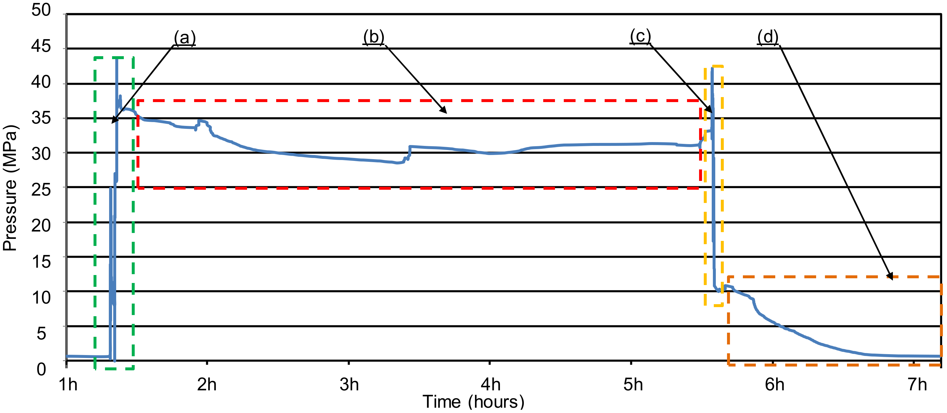
The cycle of the powered roof support work presented in fig:machines-11-00194-f004 is characterized by a change in pressure. The start of the mechanized longwall lining with working support can be seen in fig:machines-11-00194-f004 in parts (a), (c), (e). The increase in pressure in the actuator assembly is caused by the load from the rock mass. In fig:machines-11-00194-f004, part (c) shows the largest increase in pressure in the hydraulic prop of the powered roof support. On the other hand, such a high value of operating support did not cause the safety valve to open. Which is, among other things, the result of the resulting damage. On the other hand, the depicted phases of the powered roof support operation in fig:machines-11-00194-f004 in parts (b) and (d) describe the work of the hydraulic prop consisting of sliding and extending at a certain pressure. The timing of the various phases of the powered roof support operation seen in Figure 4 is variable. The resulting pressure also depends on the type of safety valve and the speed of the prop sliding.
The resulting phenomenon that applies the load of rocks on the powered roof support occurs in the case of very low-strength cap pieces at completely damaged safe rocks. The behaviour of the powered roof support under such loads depends on the weight of the rock mass, which is indicated by the measurement of pressure in the sub-piston space of the powered roof support hydraulic prop. The static value of the load generated in the longwall excavation is lower than the working bearing capacity and does not cause dynamic phenomena. Exceeding the working values led to the tightening of the powered roof support, which triggered the protections. In the powered roof support, this means triggering the safety valves by pressure drops.
The process of clamping the powered roof support resulted from the weight of the loose rock masses introduced upon the roof. Braking becomes difficult due to the hysteresis of the working valves or excess pressure safety valves. Another difficulty is the need to slow down rock masses that are already in motion. An interruption of the clamping process for this load is only possible in the event of a decrease in the weight of the rock mass due to the formation of an intrinsic natural roof. If the load is maintained above the working capacity, the powered roof support is completely clamped, with overloading consequences in the structure.
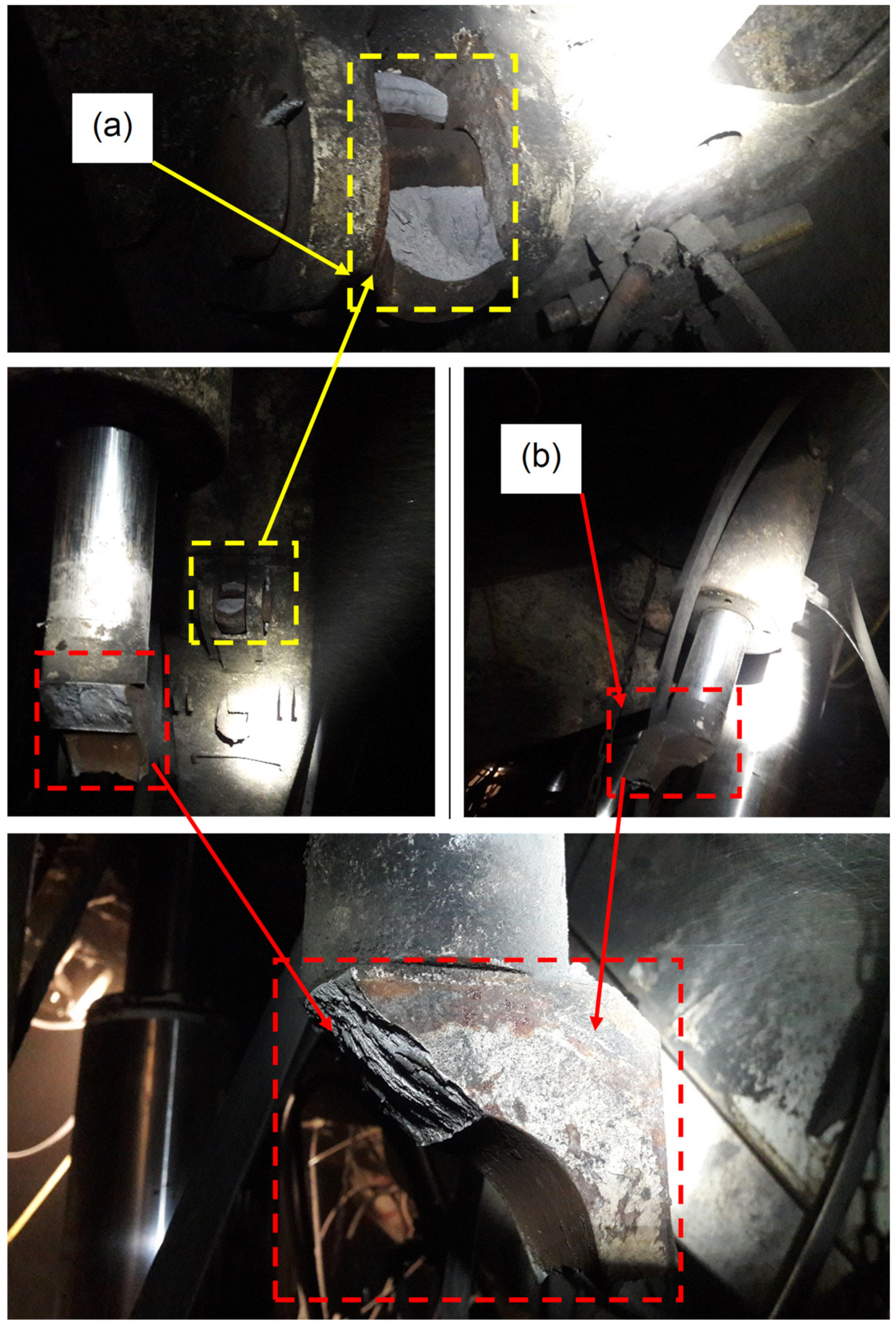
The resulting damage in the structure of the cap piece’s support actuator was in the range of the bolt holes fixing the support actuator between the cap piece’s structure and the shield (see Figure 3). The rupture of the bolt holes could have been caused by a failure to maintain the appropriate geometry of the spacing of the powered roof support section in the wall’s excavation. The problem resulting from the geometry of the expansion of the powered roof support was influenced by the workings of the rock mass. The recorded pressure in the sub-piston space of the hydraulic prop was exceeded twice with respect to its nominal work (see Figure 4). The pressure measurement in the sub-piston space of the prop, where the sampling was 100/1 s, shows that the load transfer was concentrated in the structure of the cap piece’s support actuator (see Figure 5). Specifically, it causes the bolt holes securing the support actuator to tear.

4. Discussion

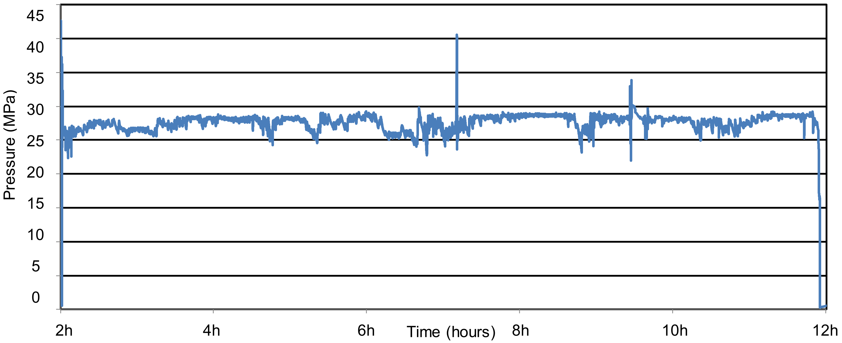
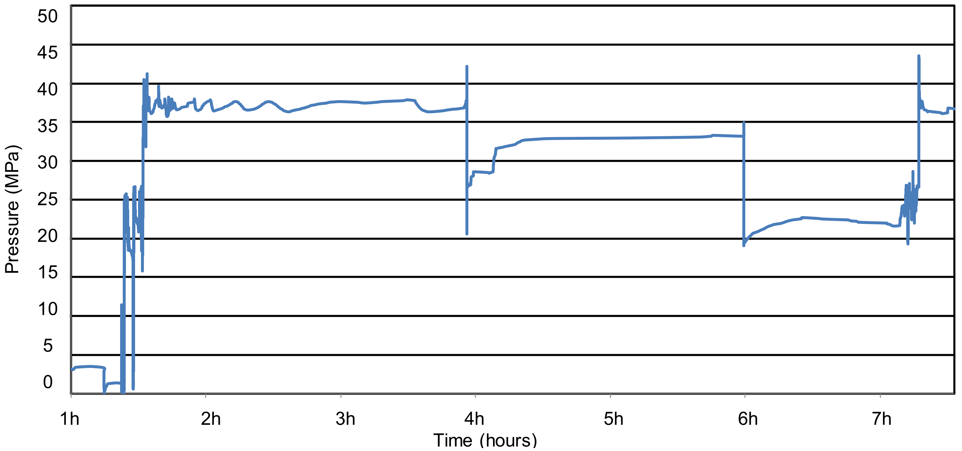
The analysed pressure increase (see Figure 6, Figure 7, Figure 8 and Figure 9) in the cap piece’s support actuator of the powered roof support resulted from the sudden clamping of the excavation. The settling of the roof probably caused this sudden clamping, resulting in a raised coal bed. The size of the bed’s settling and its course over time may vary. It may depend on the type of coal bed (coal and surrounding rocks), size, and method of its exploitation. The resulting local refraction, breakage, or cracking of the rock layer may have affected the powered roof support with a mass impactor. The analysed case in terms of damage to the cap piece’s support actuator may have caused an impact or loaded the powered roof support statically before the rock mass’s impact, the weight of which does not exceed the nominal load capacity. The excess weight should not exceed the nominal bearing capacity; the excess weight may trigger the safety valves of the support actuator or hydraulic props. If the nominal bearing capacity is exceeded, the powered roof support may be clamped, resulting in a loss of excavation functionality. In the analysed case, the nominal bearing capacity can also be exceeded due to the weight gain that is directly supported by the powered roof support.
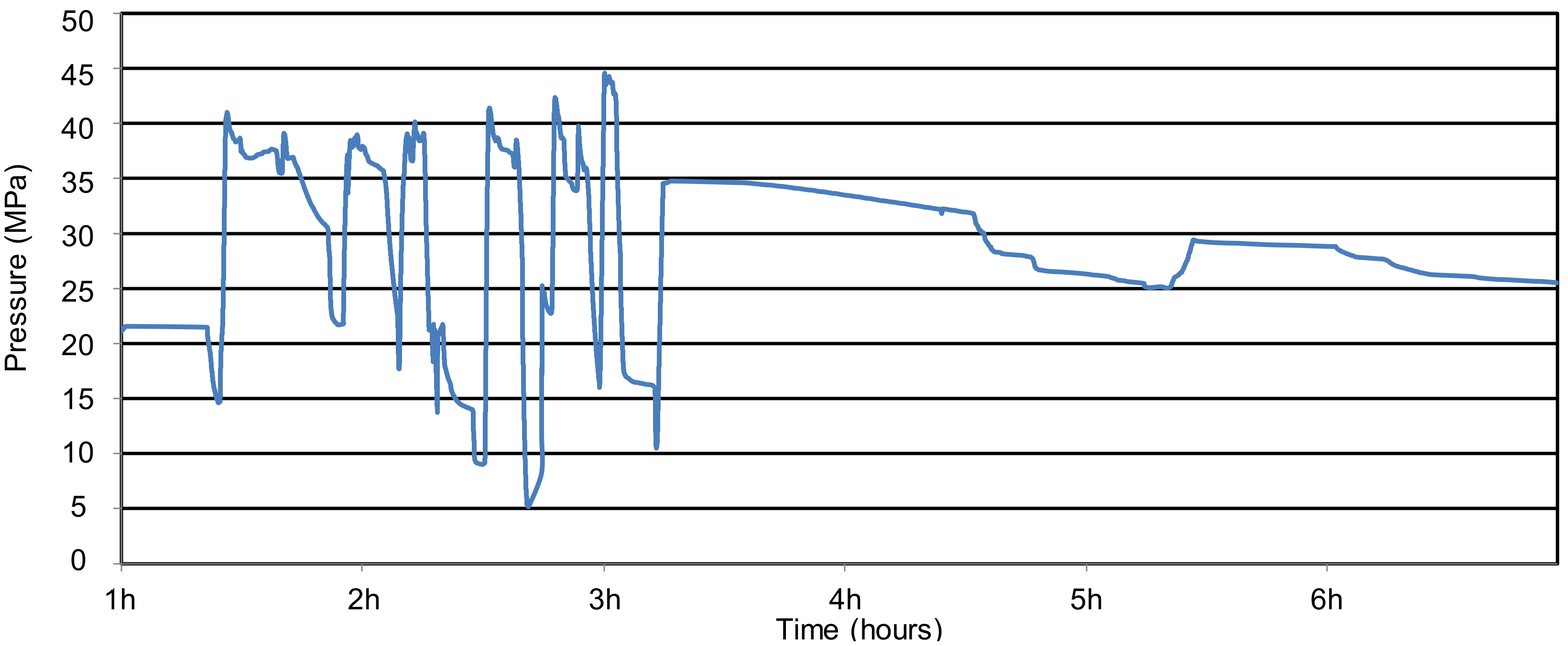
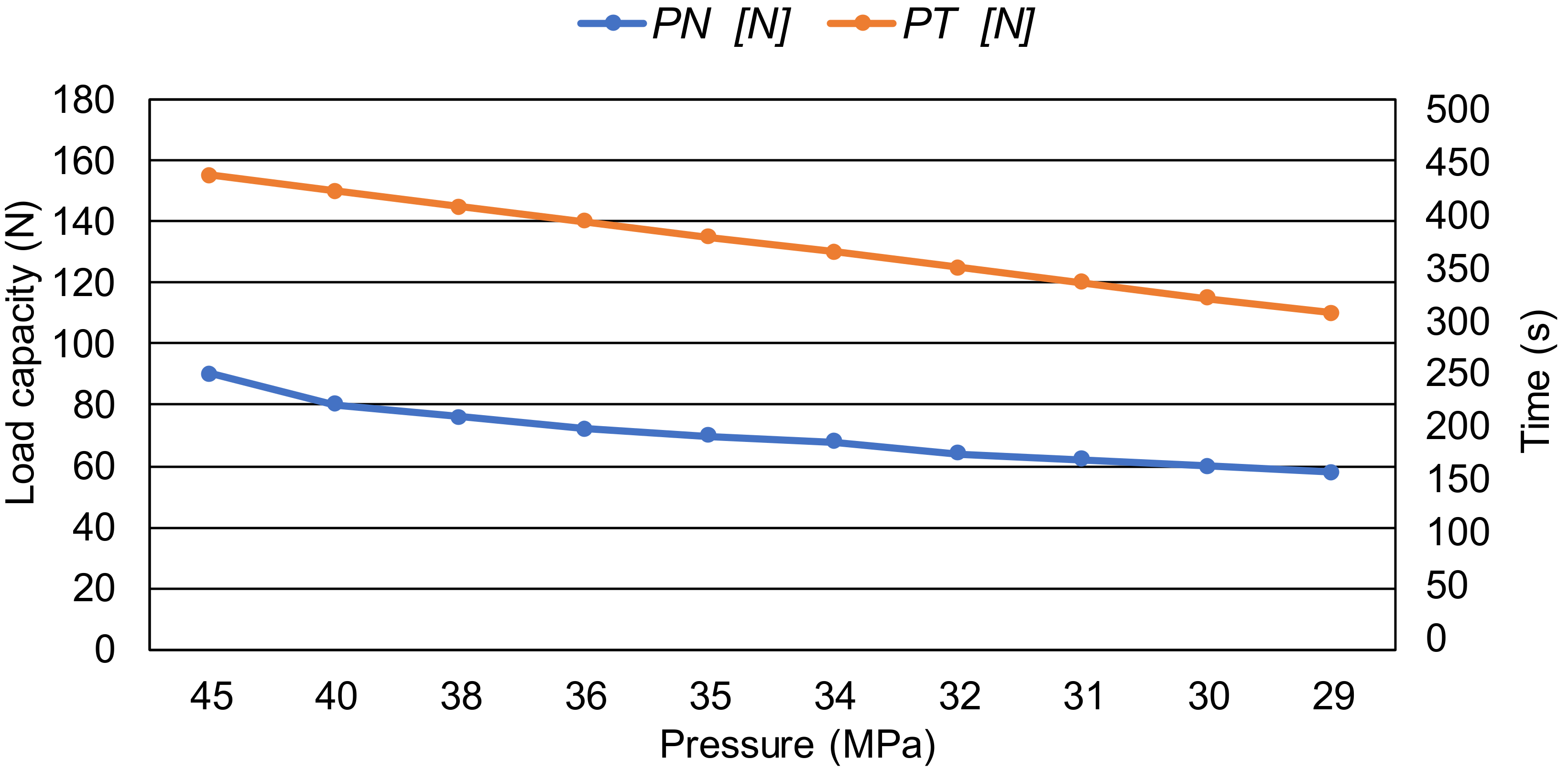
The recorded pressure in the sub-piston space (see Figure 8 and Figure 9) of the hydraulic prop shows that the operating parameters have been exceeded. Based on relation (1) comparing the over-lock operation of the floor-support actuator with the under-lock operation, the results of the obtained calculations are presented in Table 2 and illustrated in Figure 10.
The analysis of the described effects in the cap piece’s support actuator of the powered roof support was a consequence of the adverse impact of the rock mass. The result of this adverse impact of the rock mass on the support was the cracking of bolt holes, fixing it within the structure (see Figure 3). This dominant damage influenced the geometry of the powered roof support. No other damage was recorded in the powered roof support’s structure and the hydraulic props. The effects in the longwall workings indicate that the permissible amount of loading that can be carried by the mechanical roof support has been exceeded.
The effect of the unfavourable impact of the rock mass occurred when the strength of the rock mass surrounding the excavation was exceeded. The value and nature of dynamic loads in the analysed case are currently unknown. This was due to several reasons, the most important of which was the lack of sufficiently accurate calculation methods that would be accountable for all types of impacts with respect to rock masses on powered roof supports, as well as technical and organisational difficulties for conducting research in mines.
During the operation of a longwall workings, changes may occur in the rocks surrounding the workings. Which are characterized by slow changes gradually intensifying in an abrupt manner which probably affected the damage to the powered roof support structure. They result from the relaxation of rocks, starting from the load surface. These changes are called static, and the end result of this type of change can be delamination and crushing of the rocks. The powered roof support takes the load partly on the canopy and partly on the caving shield. On the other hand, the largest one is taken over by the support actuator, which connects the canopy with the caving shield. In the research analyzed, it was recognized that the most sensitive structural component of powered roof support is the roof support actuator. The roof support actuator determines the geometric behavior of the powered roof support structure during the mining longwall operation.

5. Conclusions

The difficulties in determining where and when a dynamic load on a mechanical the powered roof support occurs greatly restricts the ability to measure actual loads.
This is a significant limitation in determining what requirements a powered roof support should meet and what form of construction it should have. The impact of the rock mass in the excavation directly impacted the damage inflicted upon the cap piece’s support actuator of the powered roof support.
Based on these insights, measurements, and calculations, it can be concluded that it is possible to significantly reduce these effects by observing the following principles:
(1)
Under conditions in which a high adverse impact of the rock mass can be predicted, four props are used on the powered roof support with or without a shield.
(2)
The prop structure and the hydraulic support actuator should be adapted to carry an increased load.
(3)
Safety relief valves should be used as additional protection for the hydraulic prop and the cap piece’s support actuator.
(4)
The cap piece’s support actuator should have a safety relief valve protecting at least the over-piston space.
(5)
The capacity of the safety relief valve should be adjusted to the working surface of the cap piece’s support actuator.
(6)
Tests should be carried out with respect to the hydraulic power elements of powered roof supports in stations under static and dynamic load.
The observations of the effects of the powered roof support should involve the adverse impact of the rock mass.
The above conclusions were drawn from the research analysis. The test results obtained determined how the powered roof support should be prepared for subsequent tests. This research analysis aimed to explain the possible causes of damage to the cap piece’s actuator that is adversely loaded by a rock mass.

Funding

This research received no external funding.

Institutional Review Board Statement

Not applicable.

Informed Consent Statement

Not applicable.

Data Availability Statement

Not applicable.

Conflicts of Interest

The authors declare no conflict of interest.

References

  1. Khayrutdinov, M.M.; Golik, V.I.; Aleksakhin, A.V.; Trushina, E.V.; Lazareva, N.V.; Aleksakhina, Y.V. Proposal of an Algorithm for Choice of a Development System for Operational and Environmental Safety in Mining. Resources 2022, 11, 88. [Google Scholar] [CrossRef]
  2. Gabov, V.V.; Zadkov, D.A.; Babyr, N.V.; Xie, F. Nonimpact rock pressure regulation with energy recovery into the hydraulic system of the longwall powered support. Eurasian Min. 2021, 36, 55–59. [Google Scholar] [CrossRef]
  3. Babyr, N.; Babyr, K. To improve the contact adaptability of mechanical roof support. E3S Web Conf. 2021, 266, 03015. [Google Scholar] [CrossRef]
  4. Babyr, N.V.; Korolev, A.I.; Neupokoeva, T.V. Enhancement of powered cleaning equipment with the view of mining and geological conditions. IOP Conf. Ser. Earth Environ. Sci. 2018, 194, 032004. [Google Scholar] [CrossRef]
  5. Buevich, V.V.; Gabov, V.V.; Zadkov, D.A.; Vasileva, P.A. Adaptation of the mechanized roof support to changeable rock pressure. Eurasian Min. 2015, 2, 11–14. [Google Scholar] [CrossRef]
  6. Gabov, V.V.; Zadkov, D.A.; Stebnev, A.V. Evaluation of structure and variables within performance rating of hydraulically powered roof sup-port legs with smooth roof control. Eurasian Min. 2016, 2, 37–40. [Google Scholar]
  7. Bortnowski, P.; Gładysiewicz, L.; Król, R.; Ozdoba, M. Energy Efficiency Analysis of Copper Ore Ball Mill Drive Systems. Energies 2021, 14, 1786. [Google Scholar] [CrossRef]
  8. Bardzinski, P.; Jurdziak, L.; Kawalec, W.; Król, R. Copper ore quality tracking in a belt conveyor system using simulation tools. Nat. Resour. Res. 2020, 29, 1031–1040. [Google Scholar] [CrossRef]
  9. Kumar, R.; Singh, A.K.; Mishra, A.K.; Singh, R. Underground mining of thick coal seams. Int. J. Min. Sci. Technol. 2015, 25, 885–896. [Google Scholar] [CrossRef]
  10. Skrzypkowski, K.; Korzeniowski, W.; Zagórski, K.; Zagórska, A. Modified Rock Bolt Support for Mining Method with Controlled Roof Bending. Energies 2020, 13, 1868. [Google Scholar] [CrossRef]
  11. Prostański, D. Empirical Models of Zones Protecting Against Coal Dust Explosion. Arch. Min. Sci. 2017, 62, 611–619. [Google Scholar] [CrossRef] [Green Version]
  12. Adach-Pawelus, K.; Pawelus, D. Influence of Driving Direction on the Stability of a Group of Headings Located in a Field of High Horizontal Stresses in the Polish Underground Copper Mines. Energies 2021, 14, 5955. [Google Scholar] [CrossRef]
  13. Qiao, S.; Zhang, Z.; Zhu, Z.; Zhang, K. Influence of cutting angle on mechanical properties of rock cutting by conical pick based on finite element analysis. J. Min. Sci. 2021, 28, 161–173. [Google Scholar] [CrossRef]
  14. Ji, Y.; Ren, T.; Wynne, P.; Wan, Z.; Zhaoyang, M.; Wang, Z. A comparative study of dust control practices in Chinese and Australian longwall coal mines. Int. J. Min. Sci. Technol. 2016, 25, 687–706. [Google Scholar] [CrossRef]
  15. Kotwica, K.; Stopka, G.; Kalita, M.; Bałaga, D.; Siegmund, M. Impact of Geometry of Toothed Segments of the Innovative KOMTRACK Longwall Shearer Haulage System on Load and Slip during the Travel of a Track Wheel. Energies 2021, 14, 2720. [Google Scholar] [CrossRef]
  16. Ralston, J.C.; Reid, D.C.; Dunn, M.T.; Hainsworth, D.W. Longwall automation: Delivering enabling technology to achieve safer and more productive underground mining. Int. J. Min. Sci. Technol. 2015, 25, 865–876. [Google Scholar] [CrossRef]
  17. Bajda, M.; Błażej, R.; Hardygóra, M. Optimizing splice geometry in multiply conveyor belts with respect to stress in adhesive bonds. Min. Sci. 2018, 25, 195–206. [Google Scholar]
  18. Wajs, J.; Trybała, P.; Górniak-Zimroz, J.; Krupa-Kurzynowska, J.; Kasza, D. Modern Solution for Fast and Accurate Inventorization of Open-Pit Mines by the Active Remote Sensing Technique—Case Study of Mikoszów Granite Mine (Lower Silesia, SW Poland). Energies 2021, 14, 6853. [Google Scholar] [CrossRef]
  19. Ziętek, B.; Banasiewicz, A.; Zimroz, R.; Szrek, J.; Gola, S. A Portable Environmental Data-Monitoring System for Air Hazard Evaluation in Deep Underground Mines. Energies 2020, 13, 6331. [Google Scholar] [CrossRef]
  20. Peng, S.S.; Feng, D.; Cheng, J.; Yang, L. Automation in U.S. longwall coal mining: A state-of-the-art review. Int. J. Min. Sci. Technol. 2019, 29, 151–159. [Google Scholar] [CrossRef]
  21. Hamříková, R.; Dlouhá, D. Video tutorials for students of the master’s program. In Open Education as a Way to a Knowledge Society; DisCo, Centre for Higher Education Studies: Praha, Czech Republic, 2017; pp. 446–451. [Google Scholar]
  22. Jixiong, Z.; Spearing, A.J.S.; Xiexing, M.; Shuai, G.; Qiang, S. Green coal mining technique integrating mining-dressing-gas draining-backfilling-mining. Int. J. Min. Sci. Technol. 2017, 27, 17–27. [Google Scholar]
  23. Juganda, A.; Strebinger, C.; Brune, J.F.; Bogin, G.E. Discrete modeling of a longwall coal mine gob for CFD simulation. Int. J. Min. Sci. Technol. 2020, 30, 463–469. [Google Scholar] [CrossRef]
  24. Toraño, J.; Diego, I.; Menéndez, M.; Gent, M. A finite element method (FEM)—Fuzzy logic (Soft Computing)—Virtual reality model approach in a coalface longwall mining simulation. Autom. Constr. 2008, 17, 413–424. [Google Scholar] [CrossRef]
  25. Huaiwei, R.; Desheng, Z.; Shixin, G.; Kai, Z.; Chenyang, X.; Ming, H.; Tijian, L. Dynamic impact experiment and response characteristics analysis for 1:2 reduced-scale model of hydraulic support. Int. J. Min. Sci. Technol. 2021, 3, 347–356. [Google Scholar]
  26. Hu, S.; Ma, L.; Guo, J.; Yang, P. Support-surrounding rock relationship and top-coal movement laws in large dip angle fully-mechanized caving face. Int. J. Min. Sci. Technol. 2018, 28, 533–539. [Google Scholar]
  27. Dlouhá, D.; Kozlová, K. Knowledge assessment of student’s high school mathematics. In Proceedings of the 18th Conference on Applied Mathematics, Bratislava, Slovakia, 5–7 February 2019; Volume 1, pp. 243–252. [Google Scholar]
  28. Dubovský, V.; Dlouhá, D.; Pospíšil, L. The calibration of evaporation models against the Penman-Monteith equation on lake Most. Sustainability 2021, 13, 313. [Google Scholar] [CrossRef]
  29. Bazaluk, O.; Velychkovych, A.; Ropyak, L.; Pashechko, M.; Pryhorovska, T.; Lozynskyi, V. Influence of Heavy Weight Drill Pipe Material and Drill Bit Manufacturing Errors on Stress State of Steel Blades. Energies 2021, 14, 4198. [Google Scholar] [CrossRef]
  30. Dlouhá, D.; Pokorný, J.; Dlouhá, K. Necessity of knowledge about math in safety engineering. In E-Learning: Unlocking the Gate to Education around the Globe; DisCo, Center for Higher Education Studies: Praha, Czech Republic, 2019; pp. 380–386. [Google Scholar]
  31. Dlouhá, D.; Dubovský, V.; Pospíšil, L. Optimal calibration of evaporation models against Penman-Monteith equatíon. Water 2021, 13, 1484. [Google Scholar] [CrossRef]
  32. Doroszuk, B.; Król, R. Analysis of conveyor belt wear caused by material acceleration in transfer station. Min. Sci. 2019, 26, 189–201. [Google Scholar] [CrossRef]
  33. Buyalich, G.; Byakov, M.; Buyalich, K.; Shtenin, E. Development of Powered Support Hydraulic Legs with Improved Performance. E3S Web Conf. 2019, 105, 3025. [Google Scholar] [CrossRef]
  34. Uth, F.; Polnik, B.; Kurpiel, W.; Baltes, R.; Kriegsch, P.; Clause, E. An innovate person detection system based on thermal imaging cameras dedicate for underground belt conveyors. Min. Sci. 2019, 26, 263–276. [Google Scholar]
  35. Dlouhá, D.; Hamříková, R. Our experience with the involvement of students in the creation of study materials. In Proceedings of the 17th Conference on Applied Mathematics, Bratislava, Slovakia, 6–8 February 2018; Volume 1, pp. 301–308. [Google Scholar]
  36. Zimroz, P.; Trybała, P.; Wróblewski, A.; Góralczyk, M.; Szrek, J.; Wójcik, A.; Zimroz, R. Application of UAV in Search and Rescue Actions in Underground Mine—A Specific Sound Detection in Noisy Acoustic Signal. Energies 2021, 14, 3725. [Google Scholar] [CrossRef]
  37. Dlouhá, D.; Hamříková, R. Interactive distance materials of mathematics for VŠB-TU Ostrava. In Overcoming the Challenges and the Barriers in Open Education; DisCo, Centre for Higher Education Studies: Praha, Czech Republic, 2018; pp. 67–72. [Google Scholar]
  38. Pokorny, J.; Dlouhá, D.; Kucera, P. Study of the necessity of use virtual origin in assessment of selected fire plume characteristics. MM Sci. J. 2016, 5, 1424–1428. [Google Scholar] [CrossRef]
  39. Pokorny, J.; Mozer, V.; Malerova, L.; Dlouhá, D.; Wilkinson, P. A simplified method for establishing safe available evacuation time based on a descending smoke layer. Commun. Sci. Lett. Univ. Zilina 2018, 20, 28–34. [Google Scholar] [CrossRef]
  40. Wang, J.; Wang, Z. Systematic principles of surrounding rock control in longwall mining within thick coal seams. Int. J. Min. Sci. Technol. 2019, 29, 591–598. [Google Scholar] [CrossRef]
  41. Stoiński, K. Mining Roof Support in Hazardous Conditions of Mining Tremors. Collective Work for Editing Kazimierza Stoińskiego; The Central Mining Institute: Katowice, Poland, 2018. [Google Scholar]
  42. Dlouhá, D.; Dubovský, V. The improvement of the lake Most evaporation estimates. Inżynieria Miner. 2019, 21, 159–164. [Google Scholar]
  43. Świątek, J.; Janoszek, T.; Cichy, T.; Stoiński, K. Computational Fluid Dynamics Simulations for Investigation of the Damage Causes in Safety Elements of Powered Roof Supports—A Case Study. Energies 2021, 14, 1027. [Google Scholar] [CrossRef]
  44. Rajwa, S.; Janoszek, T.; Prusek, S. Influence of canopy ratio of powered roof support on longwall working stability—A case study. Int. J. Min. Sci. Technol. 2019, 29, 591–598. [Google Scholar] [CrossRef]
  45. Buyalich, G.; Buyalich, K.; Byakov, M. Factors Determining the Size of Sealing Clearance in Hydraulic Legs of Powered Supports. E3S Web Conf. 2017, 21, 3018. [Google Scholar] [CrossRef]
  46. Huang, P.; Spearing, S.; Ju, F.; Jessu, K.V.; Wang, Z.; Ning, P. Control Effects of Five Common Solid Waste Backfilling Materials on In Situ Strata of Gob. Energies 2019, 12, 154. [Google Scholar] [CrossRef]
  47. Buyalich, G.; Byakov, M.; Buyalich, K. Factors Determining Operation of Lip Seal in the Sealed Gap of the Hydraulic Props of Powered Supports. E3S Web Conf. 2017, 41, 1045. [Google Scholar] [CrossRef]
  48. Wang, X.; Xu, J.; Zhu, W.; Li, Y. Roof pre-blasting to prevent support crushing and water inrush accidents. Int. J. Min. Sci. Technol. 2012, 22, 379–384. [Google Scholar]
  49. Juárez-Ferreras, R.; González-Nicieza, C.; Menéndez-Díaz, A.; Álvarez-Vigil, A.E.; Álvarez-Fernández, M.I. Measurement and analysis of the roof pressure on hydraulic props in longwall. Int. J. Coal Geol. 2008, 75, 49–62. [Google Scholar] [CrossRef]
  50. Klishin, V.I.; Klishin, S.V. Coal Extraction from Thick Flat and Steep Beds. J. Min. Sci. 2010, 46, 149–159. [Google Scholar] [CrossRef]
  51. Ralston, J.C.; Hargrave, C.O.; Dunn, M.T. Longwall automation: Trends, challenges and opportunities. Int. J. Min. Sci. Technol. 2017, 27, 733–739. [Google Scholar] [CrossRef]
  52. Stoiński, K.; Mika, M. Dynamics of Hydraulic Leg of Powered Longwall Support. J. Min. Sci. 2003, 39, 72–77. [Google Scholar] [CrossRef]
  53. Frith, R.C. A holistic examination of the load rating design of longwall shields after more than half a century of mechanised longwall mining. Int. J. Min. Sci. Technol. 2015, 26, 199–208. [Google Scholar] [CrossRef]
  54. Zhao, X.; Li, F.; Li, Y.; Fan, Y. Fatigue Behavior of a Box-Type Welded Structure of Hydraulic Support Used in Coal Mine. Materials 2015, 8, 6609–6622. [Google Scholar] [CrossRef] [Green Version]
Figure 1. Scheme of a powered roof support with a ceiling support actuator: maximum expansion (a), lemniscate mechanism (1), floor base (2), hydraulic props (3), beam of sliding system (4), canopy (5), shield support (6), ceiling support actuator (7), and minimal expansion (b).
Machines 11 00194 g001aMachines 11 00194 g001b
Figure 2. Cross-section view of the actuator of the powered roof support.
Machines 11 00194 g002
Figure 3. View of the resulting damage to the canopy support actuator in the longwall: (a) a fragment of a broken bolt hole of the support actuator structure and (b) broken bolt hole of the support actuator.
Machines 11 00194 g003
Figure 4. Measuring the pressure in the over-piston space when the housing is loaded: (a) operation of the housing with working supports, (b) cycle of shifting sections of mechanized housing, (c) obtained working support during the lapping of the housing, (d) time of moving the section to a new position, and (e) working capacity within the limits of normal operation.
Machines 11 00194 g004
Figure 5. View of the arrangement of measurement sensors: (a) sensors placed in the actuator of the ceiling support and (b) sensors placed in the hydraulic prop.
Machines 11 00194 g005
Figure 6. Measuring the pressure in the cylinder of the canopy supports during the sudden clamping of the excavation.
Machines 11 00194 g006
Figure 7. Measurement analysis for the obtained pressure during the operation of the floor support actuator: section expansion time (a), working support (b), the moment when the actuator is damaged (c), and loss of required pressure due to damage (d).
Machines 11 00194 g007
Figure 8. Pressure behaviour during the loading of mechanised casing from the rock mass.
Machines 11 00194 g008
Figure 9. Registered excess of the nominal support.
Machines 11 00194 g009
Figure 10. Comparison between the over-lock operation of the floor-support actuator and the under-lock operation.
Machines 11 00194 g010
Table 1. Basic data of the analysed actuator of the powered roof support.
Technical Specifications
Diameter of the cylinder160 mm
Internal diameter80 mm
Minimum length840 mm
Maximum length1300 mm
Jump460 mm
Supply pressure250–320 MPa r
Operating pressure380 MPa
Push force at supply pressure502–643 kN
Push force at operating pressure764 kN
Pulling force at supply pressure377–482 kN
Pulling force at operating pressure573 kN
Table 2. The results of the operation of the canopy support actuator in the longwall.
Sn
(m2)
Sp
(m2)
Prp
(MPa)
Prn
(MPa)
PN
(N)
PT
(N)
0.50.2453190155
0.50.2403080150
0.50.2382976145
0.50.2362872140
0.50.2352770135
0.50.2342668130
0.50.2322564125
0.50.2312462120
0.50.2302360115
0.50.2292258110
Disclaimer/Publisher’s Note: The statements, opinions and data contained in all publications are solely those of the individual author(s) and contributor(s) and not of MDPI and/or the editor(s). MDPI and/or the editor(s) disclaim responsibility for any injury to people or property resulting from any ideas, methods, instructions or products referred to in the content.