Article

Rejection of Synchronous Vibrations of AMB System Using Nonlinear Adaptive Control Algorithm with a Novel Frequency Estimator

1
Institute of Nuclear and New Energy Technology, Tsinghua University, Beijing 100084, China
2
Collaborative Innovation Center of Advanced Nuclear Energy Technology, Beijing 100084, China
3
The Key Laboratory of Advanced Reactor Engineering and Safety, Ministry of Education, Beijing 100084, China
*
Author to whom correspondence should be addressed.
Machines 2023, 11(2), 188; https://doi.org/10.3390/machines11020188
Submission received: 30 November 2022 / Revised: 28 December 2022 / Accepted: 8 January 2023 / Published: 31 January 2023
(This article belongs to the Special Issue Selected Papers from CITC2022)

Abstract

:
This paper focuses on the synchronous vibration suppression of an active magnetic bearing (AMB) system without a rotating speed sensor. One of the most intractable problems with AMB systems is the synchronous vibration caused by the mass imbalance of the rotor. Moreover, practically all existing unbalance control algorithms require the rotating speed sensor to determine rotation speed. However, in some unique applications, it is impossible to install and use the rotating speed sensor as intended. This study provided a nonlinear adaptive control (NAC) algorithm and a modified frequency estimator to address the above issues. The proposed approach can suppress current and displacement vibrations by regulating the control structure. The frequency estimator calculates the rotating speed based on the position of the rotor at different moments, which has a quick response time, high precision, and effective tracking. The NAC algorithm can achieve unbalanced control based on the period iteration strategy. Additionally, the Lyapunov method is used to demonstrate the stability of the NAC algorithm. Finally, the experimental and simulation results also confirm the effectiveness and reliability of the overall control scheme. The results from simulations and experiments indicate that the novel frequency estimator can track the speed accurately and that its error can be regulated to within ± 0.05 Hz. The overall control schema can reduce the displacement vibration’s amplitude by 72.2% and the current vibration’s amplitude by 65.6%.

1. Introduction

The active magnetic bearing (AMB) utilizes the controllable electromagnetic force to realize the non-contact motion control of the rotor. Compared with traditional mechanical bearings, AMB has two characteristics. The first is no mechanical contact, which brings numerous benefits, including micro-friction, no wear, low power consumption, high rotating speed, no lubrication, and no sealing. Second characteristic is that the AMB system’s dynamic performance is controllable, allowing for the employment of online control algorithms for shock absorption and vibration isolation. Besides, we can also use AMB to identify unknown structural characteristics. These advantages make AMB systems widely used in various industries, including the military, ultra-clean vacuum environments, the oil and gas industry, machine tools, etc. [1,2,3,4,5,6,7].
However, due to machining and assembly errors, uneven density, and corrosion, the rotor often has a mass imbalance. The mass imbalance is the primary source of excitation for the AMB system [8]. It will cause a misalignment of the rotor’s geometric and inertial axis. And it will also result in deflection and internal stress on the rotor, causing the rotor, stator, and base to vibrate, which will reduce the efficiency of the system and even lead to various accidents in severe cases. Therefore, the suppression of the unbalance vibrations is a key issue in the AMB system.
Dynamic balancing is typically utilized to lessen the mass imbalance. However, this approach has significant time-consuming and complex procedures as drawbacks. Fortunately, the AMB has active control qualities, which implies that the online unbalance control algorithms can suppress the unbalanced vibration. The unbalance control has been widely studied since the 1980s. The two classifications used to categorize the existing unbalance control methods are unbalance compensation and automatic balancing. The former is to keep the rotor rotating around its geometric axis. These methods are suitable for high-precision occasions. However, when the rotating speed is too high, it will lead to saturation of the power amplifiers. The latter is to force the rotor to rotate around the inertia axis. These methods have the advantages of lowering house vibration, preventing amplifier saturation, minimizing reactive power loss, and passing rigid mode critical speed [9,10].
Advanced nonlinear control techniques are employed in the unbalanced control of AMB systems to address the drawbacks of linear controllers, such as the waterbed effect [11,12,13]. The sliding mode control scheme with global invariance was proposed in [14] to optimize the performance of the auto-centering control of the AMB system. Tung et al. [15] used a fuzzy gain tuning mechanism to realize the unbalance vibration suppression. However, these control algorithms are usually complicated to implement. The notch filter [16,17,18] is widely employed in unbalance vibration control of AMB systems due to its advantages of simplicity, independence from the mathematical model, strong practicability, and reduced calculation. Peng proposed two modified notch filters in references [19] and [20]. An optimal notch filter was designed to realize synchronous vibration control for a magnetically suspended centrifugal compressor [19]. However, this method needs to calculate the optimal phase angle corresponding to different rotating speeds, and the implementation is complicated. A two-stage notch filter was proposed for synchronous vibration control of the magnetically suspended rotor system [20]. Herzog et al. [21] designed a generalized multi-variable notch filter to reject the unbalance vibration, which revises the poor stability problems with conventional notch filters and presents a unified view for both the “notch filter” approach and the “adaptive feed-forward compensation” scheme. Moreover, this method needs to calculate the parameter matrix at different rotating speeds in advance and store it in the look-up table. However, the notch filter may affect the closed-loop stability of the AMB system.
The adaptive feed-forward compensation approach, when compared to the notch filter, not only has the benefits of the notch filter but also resides in the outer loop of the control loop, maintaining the closed-loop system’s stability margin [22]. Direct and indirect adaptive feed-forward vibration controllers (AFVCs) have been designed to accomplish both displacement nulling and current nulling [23]. Analogously, Turker et al. [24] realized the displacement nulling and current nulling based on the recursive least square technique. However, the approaches suggested in references [23,24] are both vulnerable to local optimums. Zhou et al. [25] utilized the least mean square (LMS) method to track the displacement vibration phase and the influence coefficient algorithm to compensate for the synchronous vibration. However, this control scheme is complicated. Zhu et al. [26,27,28] implemented the unbalance compensation using the recursive seeking algorithm, the variable step size real-time iterative seeking algorithm, and the variable angle compensation algorithm, respectively. He et al. [29] used the iterative learning control (ILC) method based on the frequency domain approach to suppress the unbalance vibration for the MIMO AMB system. Nonami et al. [30] proposed a Fourier coefficient adaptation algorithm to suppress the unbalance vibrations of the AMB system. However, this algorithm’s sampling period (iteration period) is constant, which lessens the method’s robustness.
Most of the above-stated methods require the rotating speed of the rotor to be determined by the rotating speed sensor. However, the speed sensor’s dependability is limited, and a significant inaccuracy might arise in a high-temperature, high-pressure environment. Moreover, the rotating speed sensor might not be able to be installed ordinarily due to the restricted space inside the mechanical structure. In general, it is feasible to estimate the rotational speed using the vibration signals of the AMB system. Yang et al. [31] designed a quadrature phase locked loop algorithm to obtain the rotating speed. However, the error of this method is relatively large. Wu et al. [32] designed a phase shift second-order generalized integrator frequency-locked loop to achieve the rotating speed observation. However, this algorithm will be affected by the harmonic components. Reference [30] designed a frequency estimation algorithm to calculate the rotating speed. However, the effect of the frequency estimation is closely related to the initial value of the difference equation. Vahedforough et al. [22] used a modified adaptive observer method to estimate the rotating speed of the rotor and combined it with the AFB algorithm to reject the unbalance vibration. However, this frequency tracker possesses a slow convergence rate. An adaptive notch filter [33,34] was used to estimate the rotating speed of the AMB system. However, these algorithms are sensitive to noise. Bodson [35] gave a detailed overview of available approaches for the estimation of an unknown frequency. The methods include the extended Kalman filter, neural network theory, adaptive notch filter, fast Fourier transform, and phase-lock loop (PLC). However, in terms of robustness, accuracy, and tracking performance, the aforementioned frequency estimation algorithms are challenging to simultaneously meet the requirements of the unbalance control of the AMB system.
Aiming at the limitations of previous research, this paper proposes a nonlinear adaptive control (NAC) algorithm combined with a novel frequency estimator to suppress the synchronous vibrations of the AMB system. This control method can achieve automatic balancing and unbalance compensation by switching the control structure. The frequency estimator calculates the rotating speed based on the position of the rotor. Therefore, its response time is short, and its tracking performance is excellent. Different from the reference [28], the NAC algorithm’s iteration period is adaptively adjusted by the rotating speed and iteration parameter, which makes the algorithm more adaptive. Firstly, this paper describes the 4-DOF AMB rigid rotor model. Then, the overall structure of the strategy with the frequency estimator and NAC algorithm is presented. Meanwhile, the principles of the frequency estimator and the NAC algorithm are analyzed. Moreover, the stability of the NAC algorithm is proven by the Lyapunov method. Finally, simulations and experiments are performed to demonstrate the reliability of the overall control scheme.

2. Dynamic Model of 4-DOF AMB Rotor System

As shown in Figure 1, a typical AMB system includes a shaft, power amplifiers, sensors, a controller, radial and axial magnetic bearings, etc. In this work, the rotating speed of the rotor is lower than its first bending critical frequency. Therefore, the rotor of the AMB system in this work can be regarded as a rigid rotor. In Figure 1, O x y z is the fixed coordinate system; G and I are the geometric and inertial centers, respectively; and l g and l i are the geometric axis and inertial axis of the rotor, respectively.
The dynamic model of the rotor can be expressed as follows:
M q ¨ i + G q ˙ i = B u f
where M is the mass matrix, G is the gyroscopic matrix, u f = f x A f x B f y A f y B T is the electromagnetic force vector, and q i = β i ,   x i , α i ,   y i T is the generalized coordinate vector of the inertial center I .
Since the rotor moves in a small range near the equilibrium point, u f can be treated linearly as follows:
u f = K s q b + K i i
where q b = x b A ,   x b B ,   y b A ,   y b B T is the generalized coordinate vector of the rotor dis- placement on the upper and lower AMB planes, K s = diag K s A ,   K s B ,   K s A ,   K s B is the displacement negative stiffness matrix, K i = diag K i A ,   K i B ,   K i A ,   K i B is the current stiffness matrix, and i = i x A ,   i x B ,   i y A ,   i y B T is the control current vector.
Based on the geometric relationship shown in Figure 1, we can get:
q b = a 1 0 0 b 1 0 0 0 0 a 1 0 0 b 1 q c = B T q c             q s e = c 1 0 0 d 1 0 0 0 0 c 1 0 0 d 1 q c = C q c
where q c = β c ,   x c , α c ,   y c T is the generalized coordinate vector of the geometric center G, and q s e = x s e A   , x s e B , y s e A , y s e B T is the generalized coordinate vector of the rotor displacement on the upper and lower displacement sensor planes.
When the rotor possesses the mass imbalance, the relationship between q c and q i can be written as follows:
q i = q c + δ sin Ω t + ξ e cos Ω t + φ δ cos Ω t + ξ e sin Ω t + φ
where δ and e are the dynamic and static imbalances, respectively, and ξ and φ are the initial phases of the dynamic and static imbalances, respectively.
Substituting Equations (2)–(4) into (1), the dynamic model of the geometric center of the rotor with mass imbalance can be written as follows:
M q ¨ c + G q ˙ c = B K s B T q c + B K i i + Δ f
where Equation (6) is as follows:
Δ f = J t J z Ω 2 δ sin Ω t + ξ m Ω 2 e cos Ω t + φ J z J t Ω 2 δ cos Ω t + ξ m Ω 2 e sin Ω t + φ
Because of the existence of K s , the open-loop system depicted in Equation (5) is unstable. Hence, the closed-loop feedback control is used to achieve stability. The block diagram of the closed-loop AMB system is shown in Figure 2, where G c is the feedback controller, G w is the power amplifier matrix, and K se is the displacement sensor gain matrix.

3. Concrete Implementation of NAC Algorithm with the Frequency Estimator

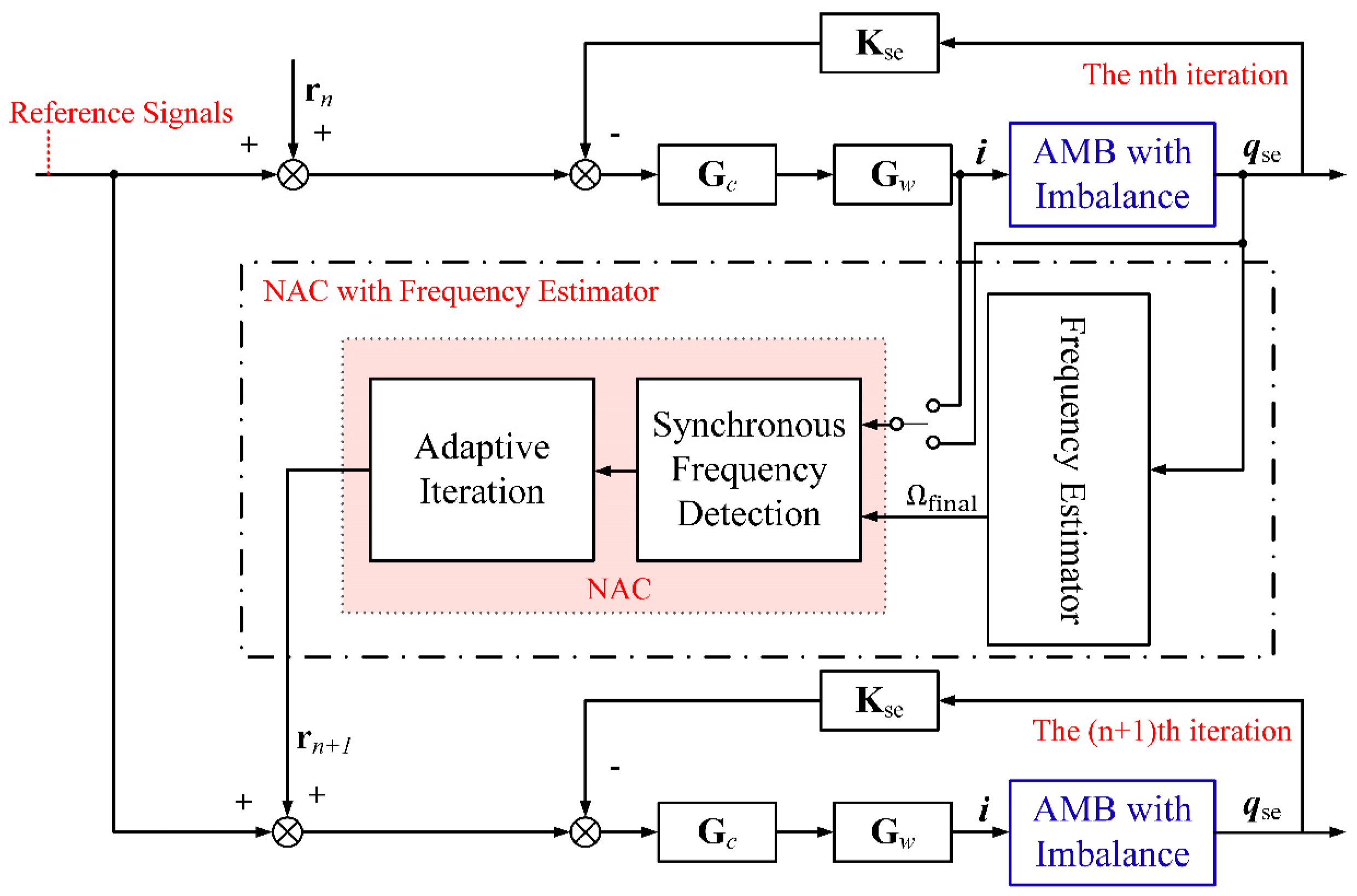
In order to eliminate the unbalance vibration caused by the disturbance shown in Equation (6), this note designed an NAC algorithm combined with a novel frequency estimator. The overall algorithm structure is shown in Figure 3. Firstly, the frequency estimator module can accurately calculate the rotating speed of the rotor and achieve speed tracking based on displacement sensors signals. Then, the NAC algorithm takes the current and displacement vibration signals as the suppression targets, respectively, and realizes the automatic balancing and unbalance compensation.

3.1. Frequency Estimator

Actually, the unbalanced vibration signals themselves contain the rotating speed information. Therefore, we can use the online algorithm to calculate the rotating speed of the vibration signal. The rotating speed signal must exhibit real-time, high precision, and dependability properties for the AMB system’s unbalance control, which places strict demands on the frequency estimator.
The novel frequency estimator proposed in this note is to simulate the working principle of the rotating speed sensor. As shown in Figure 4, the rotor performs synchronous positive precession in the air gap of AMB. Here, P k = x k ,   y k T and P k m = x k m ,   y k m T are the rotor position vectors at times k and k + 1 , where k is the sampling time. Next, we can determine the angle difference Δ θ according to the positions of the rotor P k and P k m , as follows:
Δ θ = tan 1 P k × P k m 2 P k · P k m
As well, the rotating speed can be written as follows:
Ω e Δ θ m · T s = 1 m · T s · tan 1 P k × P k m 2 P k · P k m
where m is the time difference between the two rotor position vectors, T s is the sampling period, and and × denote the dot product and cross product of vectors, respectively.
Usually, the displacement vibration signals not only contain synchronous components but also include noise and harmonic components. As a result, Ω e will undoubtedly depart from the genuine rotating speed value, indicating that Ω e contains an error. This work designs a double-loop filtering module (DLFM) and a real-time reference averaging module (RRAM) to enhance the accuracy and robustness of the frequency estimator. Figure 5 depicts the flow chart of the frequency estimator, where the core principle of the initial estimation module (IEM) is Equation (8).
As illustrated in Figure 5, the DLFM based on a dual-loop filtering structure can significantly minimize the error of Ω e . Moreover, the DLFM requires a small amount of calculation and is convenient for development and application. However, there may be gross errors in the output of DLFM due to the harmonic components. The RRAM can effectively identify and remove gross errors in real time. And it can also further improve the precision of the frequency estimator. Finally, the output of the frequency estimator, Ω f i n a l , can be utilized to suppress imbalanced vibrations.

3.2. NAC Algorithm

The NAC algorithm contains two parts: synchronous frequency detection and adaptive iteration. The input of the NAC algorithm is the displacement or current error signals. Here, we use e k = e x A ,   e x B T to denote the error signal.

3.2.1. Synchronous Frequency Detection

As mentioned above, in addition to the synchronous components, e k also contains noise and harmonic interference. The synchronous frequency detection can calculate the synchronous DC components of the error signal e k . This method can adapt to the applications where the speed varies with time. In addition, it is a simple and easy-to-implement method based on the Fourier analysis, as follows:
e c n = p = n 1 λ + 1 λ n k = 1 N p e p k cos ψ p k p = n 1 λ + 1 λ n N p
e s n = p = n 1 λ + 1 λ n k = 1 N p e p k sin ψ p k p = n 1 λ + 1 λ n N p
where e c n = ( e c A n ,   e c B n ) T and e s n = e s A n ,   e s B n T are the synchronous DC components in the n th iteration period, n is the number of iterations, p is the count of the rotation periods, N p is the number of sampling points in the p th rotation period, and e p k is the displacement or current error signal in the p th rotation period. Finally, ψ p k is the rotor phase, which we can obtain by interpolation, as follows:
ψ p k = ψ p k 1 + 2 π Ω f i n a l T s
If ψ p k is greater than 2 π , we assume that the rotor rotates once, then p = p + 1 and ψ p 0 = 0 . Equations (9) and (10) state that the NAC algorithm’s iteration period is equal to λ times the rotation period, where λ is an integer greater than zero. Therefore, the rotational speed and λ are both used to modify the iterative period. Changing λ in the right way can enhance the anti-interference performance of the algorithm.

3.2.2. Adaptive Iteration

The adaptive iteration module takes the synchronous DC components e c n and e s n as the objective function and makes them converge to zero. Define a n = a A n ,   a B n T and b n = b A n ,   b B n T are the Fourier coefficients of the feed-forward compensation signals, which can be expressed as follows:
r ψ p k = a A n 1 sin ψ p k + b A n 1 cos ψ p k a B n 1 sin ψ p k + b B n 1 cos ψ p k a A n 1 cos ψ p k b A n 1 sin ψ p k a B n 1 cos ψ p k b B n 1 sin ψ p k
The adaptive law is as following:
a A n + 1 = a A n w a A n + 1 e c A n + 1 a B n + 1 = a B n w a B n + 1 e c B n + 1 b A n + 1 = b A n w b A n + 1 e s A n + 1 b B n + 1 = b B n w b B n + 1 e s B n + 1
where w a A , w a B , w b A and w b B are the iteration factors, which can be written as follows:
w a A n + 1 = w a A n s g n e c A 2 n e c A 2 n + 1 w a B n + 1 = w a B n s g n e c B 2 n e c B 2 n + 1 w b A n + 1 = w b A n s g n e s A 2 n e s A 2 n + 1 w b B n + 1 = w b B n s g n e s B 2 n e s B 2 n + 1
The initial iteration parameters are as follows:
( a A 0 a B 0 b A 0 b B 0 ) = 0 0 0 0 ( e c A 0 e c A 0 e s A 0 e s B 0 ) = 0 0 0 0 ( w a A 0 w a B 0 w b A 0 w b B 0 ) = w 0 w 0 w 0 w 0
where w 0 is the initial value of the iteration factor, which affects the iteration step size of the NAC algorithm. Moreover, the NAC algorithm proposed in this note is nonlinear, and w 0 has a perceptible effect on the stability of the algorithm.

3.3. Asymptotic Stability of the NAC Algorithm

It is crucial for the AMB system to operate steadily and dependably. The above analyses show that the w 0 affects the asymptotic stability of the algorithm. Therefore, it is essential to analyze the effect of w 0 on the asymptotic stability of the NAC algorithm. Actually, the acceleration and deceleration time of the rotor is much larger than the processing time of the digital control system. As a result, it is only necessary to prove the asymptotic stability of the algorithm at a steady-state speed. When the rotor is slender, the gyroscopic effect can be ignored, and the rotor movements in the radial x and y directions can be approximated as decoupled. Taking e x A = x s e A as an instance, after adding the overall control scheme, it can be written as follows:
e x A = Π r a A sin Ω t + ϱ r + b A cos Ω t + ϱ r Π d a d A sin Ω t + ϱ d + b d A cos Ω t + ϱ d
where a d A and b d A are the Fourier coefficients of disturbance signal at the A end. As shown in Figure 2, define G r x j Ω = Π r e j ϱ r to be the transfer function from the feed-forward compensation signal to the displacement signal, and G d x j Ω = Π d e j ϱ d to be the transfer function from the disturbance signal to the displacement signal.
Substituting Equation (16) into Equations (9) and (10), we can get:
e c A n = 1 2 Π r b A cos ϱ r + Υ c A + Π r a A sin ϱ r e s A n = 1 2 Π r a A cos ϱ r + Υ s A Π r b A sin ϱ r
where Υ cA and Υ s A are the DC components of the disturbance signal, which can be written as follows:
Υ c A = Π d b d A cos ϱ d + Π d a d A sin ϱ d Υ s A = Π d a d A cos ϱ d Π d b d A sin ϱ d
Based on the adaptive iteration, we can get:
e c A n + 1 = e c A n 1 2 Π r w b A n e c A n cos ϱ r + w a A n e s A n sin ϱ r e s A n + 1 = e s A n + 1 2 Π r w b A n e c A n sin ϱ r w a A n e s A n cos ϱ r
The Lyapunov method is used to prove the asymptotic stability of the NAC algorithm. Here, we construct the Lyapunov function as follows:
Γ A n = e c A n 2 + e s A n 2
According to the Lyapunov stability theorem, the asymptotic stability condition is Γ A n 0 and Γ A n + 1 Γ A n < 0 . Obviously, the first condition is satisfied for the second, as follows:
Γ A n + 1 Γ A n = 1 4 Π r 2 w b A n e c A n sin ϱ r w a A n e s A n cos ϱ r 2     + 1 4 Π r 2 w b A n e c A n cos ϱ r + w a A n e s A n sin ϱ r 2     + Π r w b A n e s A e c A n sin ϱ r w a A n e s A 2 n cos ϱ r     Π r w a A n e s A e c A n sin ϱ r + w b A n e c A 2 n cos ϱ r
In the NAC algorithm, the iteration factors were w a A n = w b A n , and w a A n = | w b A n = w 0 | . Therefore, the Equation (21) can be rewritten as follows:
Γ A n 1 Γ A n = e s A n 2 + e c A n 2 1 4 Π r 2 w a A n 2 Π r w a A n cos ϱ r
The stability condition of the NAC algorithm is as follows:
1 4 Π r 2 w a A n 2 Π r w a A n cos ϱ r < 0
Based on Equation (23), as long as w 0 < 4 cos ϱ r Π r , the asymptotic stability of the NAC algorithm can be guaranteed. Similarly, when e x A = i x A , the asymptotic stability condition is w 0 < 4 cos ς r Ξ r . Define G r i j Ω = Ξ r e j ς r to be the transfer function from the feed-forward compensation signal to the current signal. This subsection analyzes the asymptotic stability of the NAC algorithm and derives the stability conditions when the error signal is the displacement or current signal, respectively.

4. Simulation and Experimentation

4.1. Simulation

This paper conducted a series of simulations to verify the effectiveness of the overall control scheme. The parameters of the simulation model are shown in Table 1. The rotating speed is set to 6000 rpm, which is close to the second-order rigid mode of the rotor. The vibration amplitude of the rotor is relatively large at this time. The maximum number of iteration steps set in the simulation is 1000 steps. The controller sampling frequency is set to 10 kHz. The eccentricity of the rotor is set to 0.01 m. The effect of the frequency estimator and the NAC algorithm is as follows.
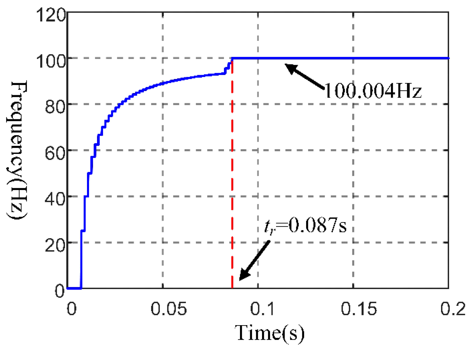
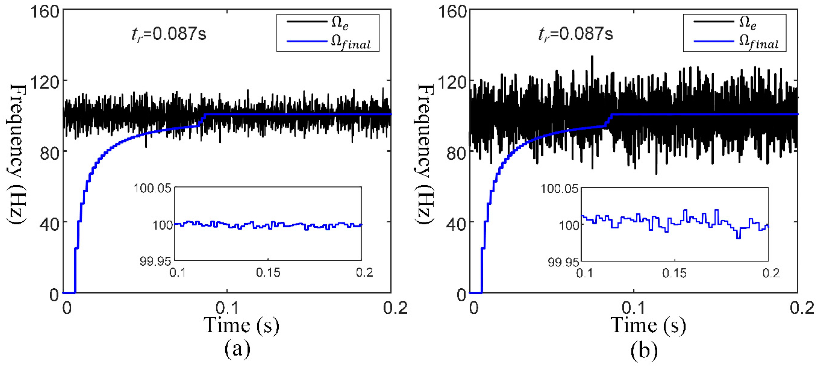
Figure 6 and Figure 7 show the simulation results of the frequency estimator. Define t r as the response time. Figure 6 shows the response curve of the frequency estimator, and t r is 0.087 s. Moreover, the response curve is characterized by a sudden increase toward the end of the response. The convergence result of the frequency estimator is 100.004 Hz, and the calculation error is within ± 0.01 Hz. In order to verify the noise immunity of the frequency estimator, the displacement signals with signal-to-noise (SNR) ratio of 13 dB and 20 dB are used as the input signals of the frequency estimator in this paper. As shown in Figure 7, Ω e is the output of the IEM, and its response time is zero. The error of Ω e is substantially less when SNR is 20 dB than when it is 13 dB. Moreover, the error of f i n a l is much smaller than that of Ω e , and is within ± 0.05 Hz. Besides, the response times corresponding to the two cases in Figure 7 are consistent with the corresponding response times in Figure 6, indicating that the response time of the frequency estimator is not affected by the noise.
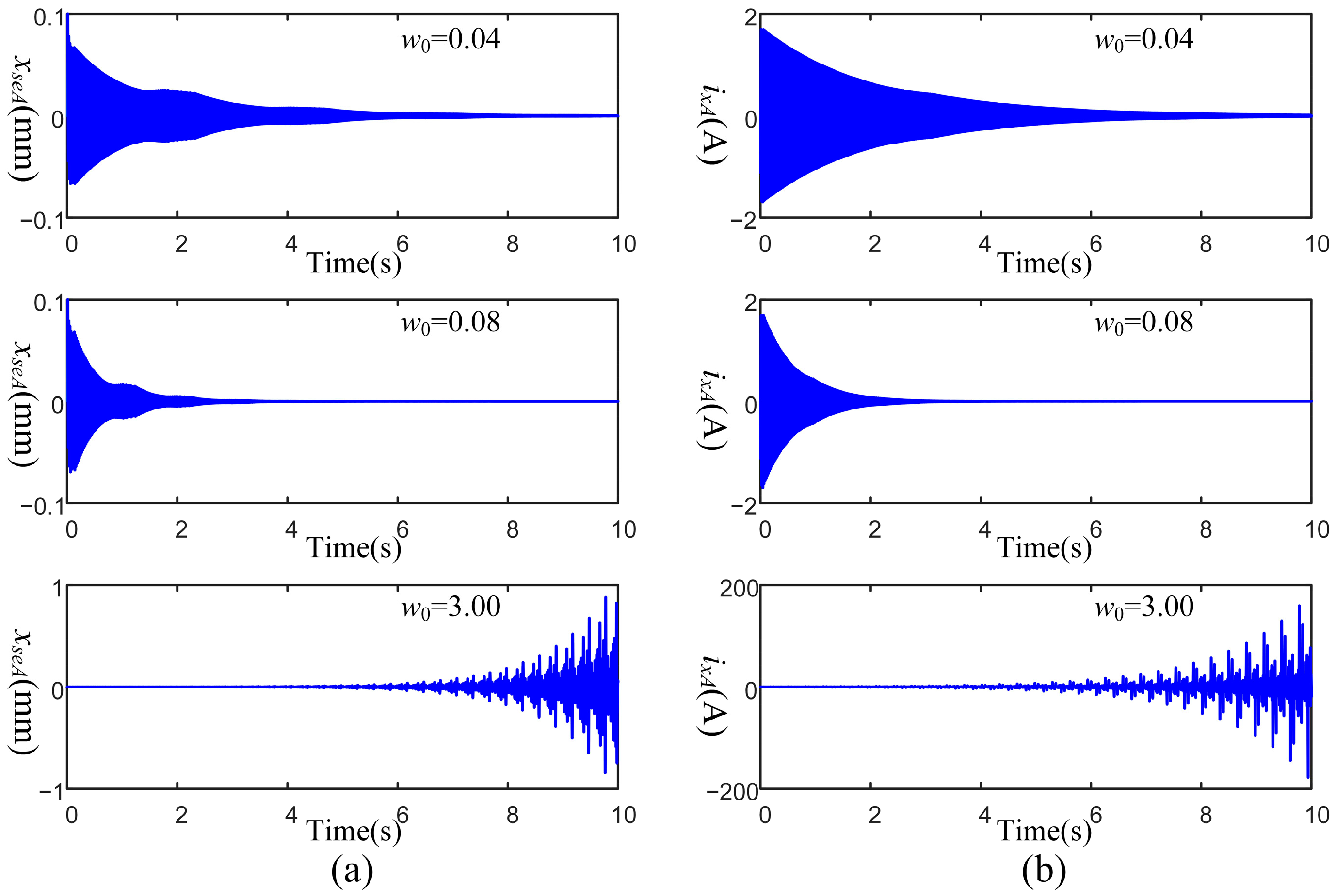
The simulation results of the overall control scheme are shown in Figure 8. The NAC algorithm uses the rotating speed calculated by the novel frequency estimator to realize displacement vibration elimination and current vibration elimination, respectively. As shown in Figure 8a, the convergence time of the displacement vibration amplitude will be shortened when the initial iteration factor is large. However, once the initial iteration factor exceeds the stability range, the system will become unstable, and the vibration amplitude will diverge. Similarly, the current vibration elimination also has such a phenomenon, which is consistent with the previous theoretical analyses.

4.2. Experiment

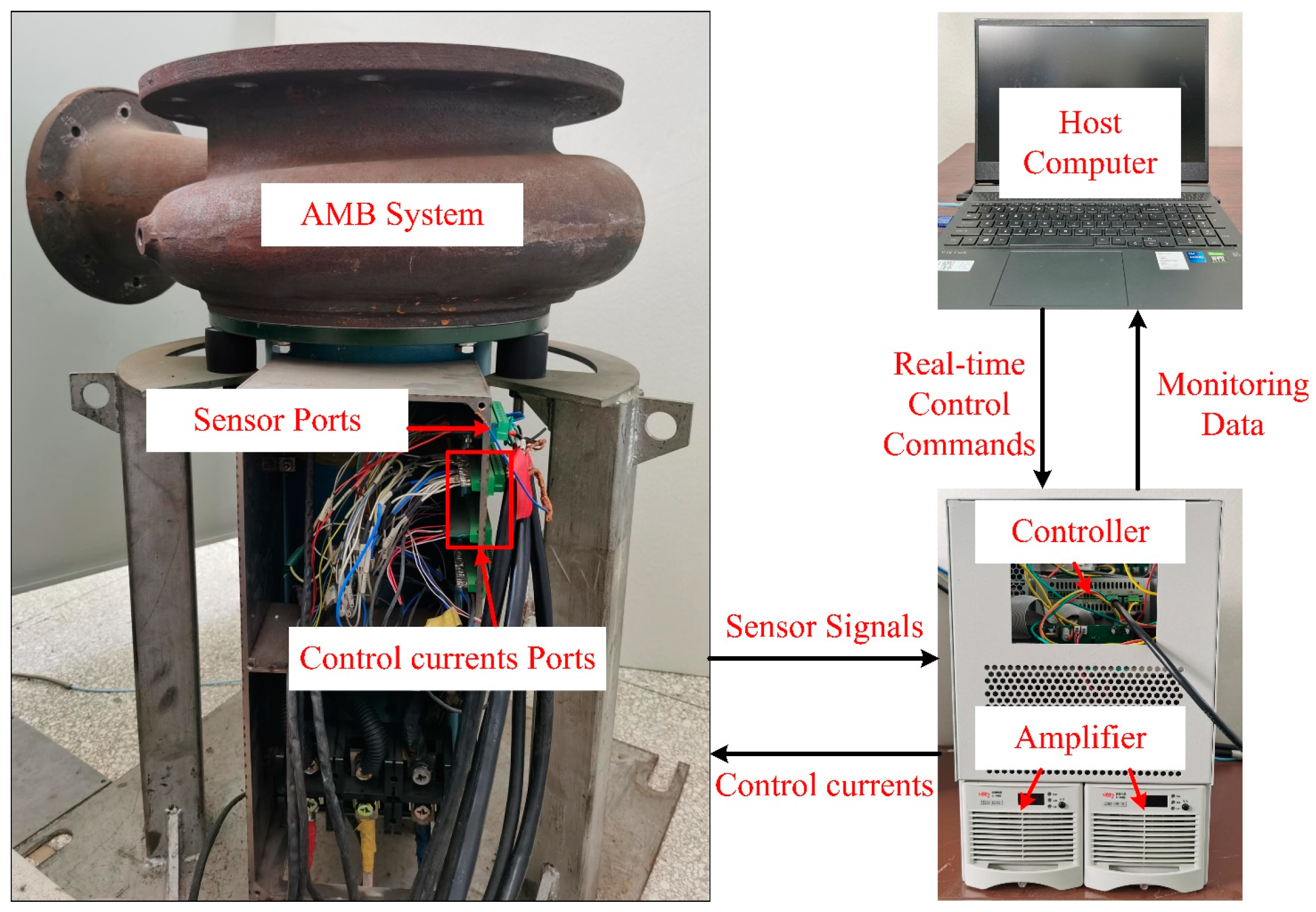
The effectiveness of the proposed algorithm is verified in an actual AMB system. As shown in Figure 9, the experimental device is a magnetically suspended compressor, whose parameters have been shown in Table 1. The rotor is placed vertically and has blades on top. This setup has two sets of 16-pole radial AMBs, and one set of axial AMBs mounted on the end of the rotor. The displacement sensors are eddy current sensors, which are installed near the radial AMBs and axial AMB to measure the displacement of the rotor. The control software is stored in the DSP chip-based digital control system.
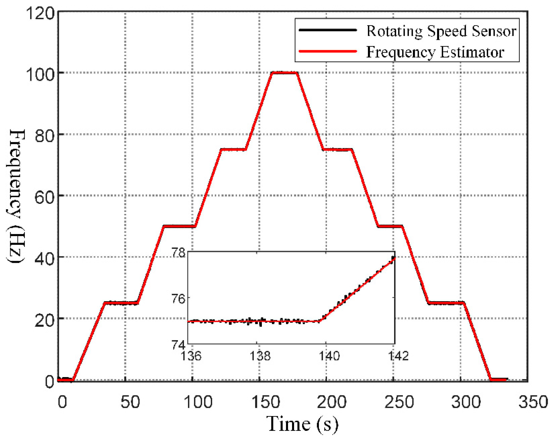
We used the rotating speed sensor as a control group to improve the experimental results’ dependability. The rotating speed is set to increase from 0 Hz to 100 Hz (6000 RPM), and then to decrease from 100 Hz to 0 Hz. Figure 10 shows the experimental results of the rotating speed sensor compared to the frequency estimator when the rotating speed varies in a straight line with time. The black line represents the rotating speed measured by the rotating speed sensor, and the red line represents the rotating speed calculated by the frequency estimator. Since the response time of the frequency estimator is extremely short, it has already completed the response when the rotor is in a suspended state. As shown in Figure 10, the frequency estimator and rotating speed sensor are almost perfectly synchronized.
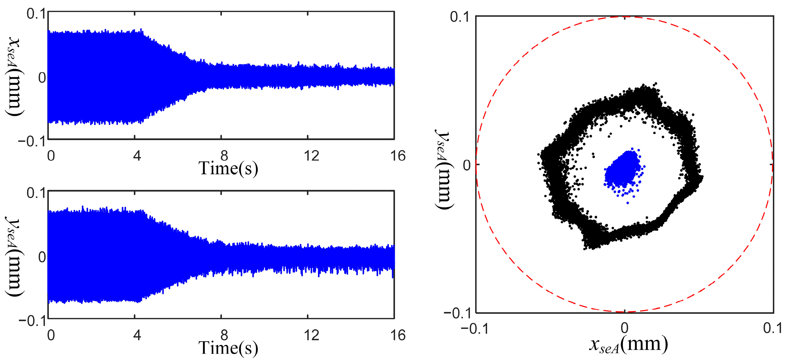
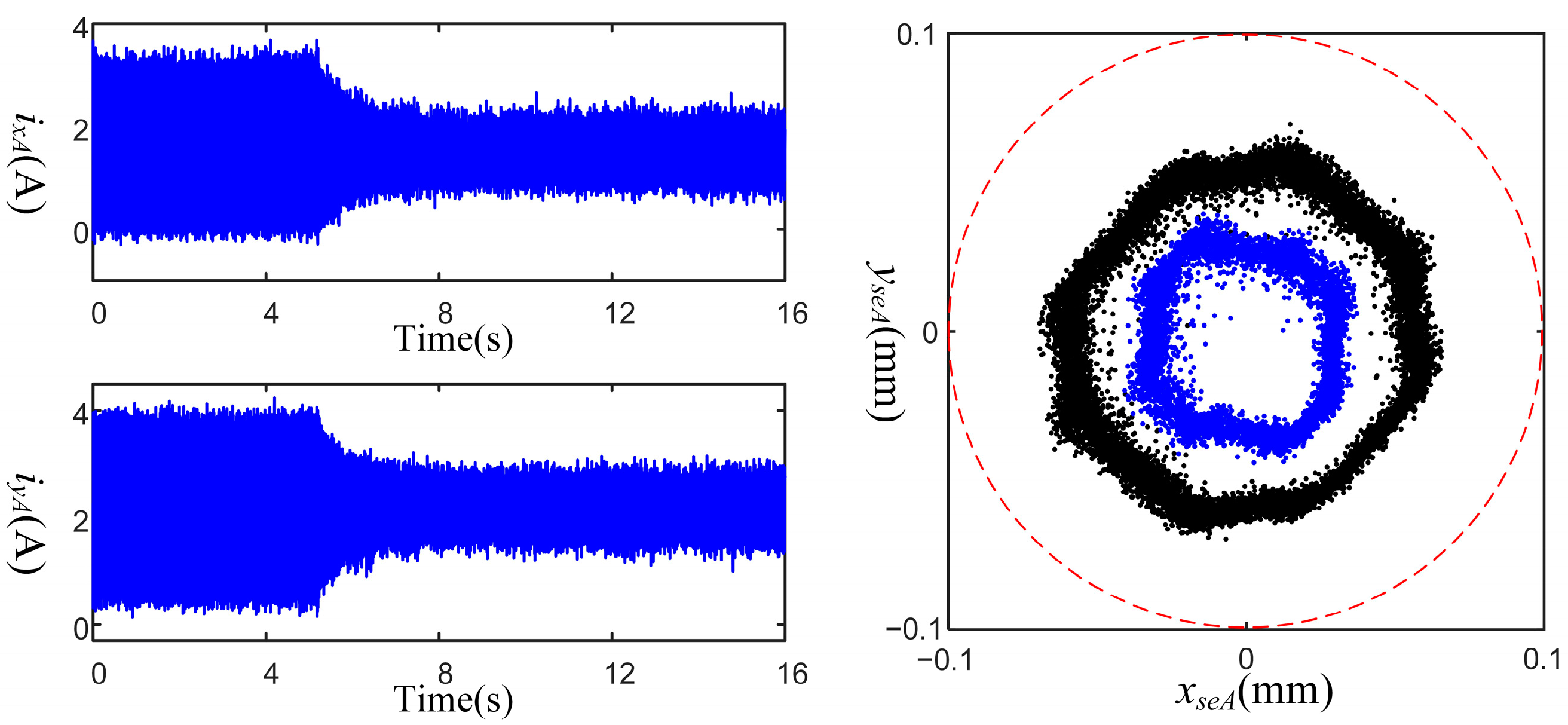
The effectiveness of the overall control scheme in displacement vibration suppression and current vibration suppression at a steady-state speed is verified. The rotating speed is 6000 rpm (100 Hz), which is close to the second-order rigid mode of the rotor. The initial iteration factor is set to 0.08. Figure 11 and Figure 12 show the experimental results of displacement vibration elimination and current vibration elimination, respectively, and the comparison results of the A-end trajectories before and after convergence in these two cases. As shown in Figure 11, after applying the control, the displacement vibration amplitude converges quickly within 3.7 s, and the contrast of the A-end trajectories before and after convergence is obvious. In Figure 12, the current vibration amplitude converges within 2.8 s. According to the simulation results, both displacement vibration and current vibration converge in 3.2 s when the initial iteration factor is 0.08. The simulation and experimental results are nearly identical. And at the same time, we can see that the trajectory of the A-end has also shrunk. When the current vibrations are suppressed, the electromagnetic force vibrations will also be suppressed to a large extent, which is equivalent to automatic balance. In this case, the rotor will rotate around its inertial axis, and the displacement vibrations will show signs of reduction.
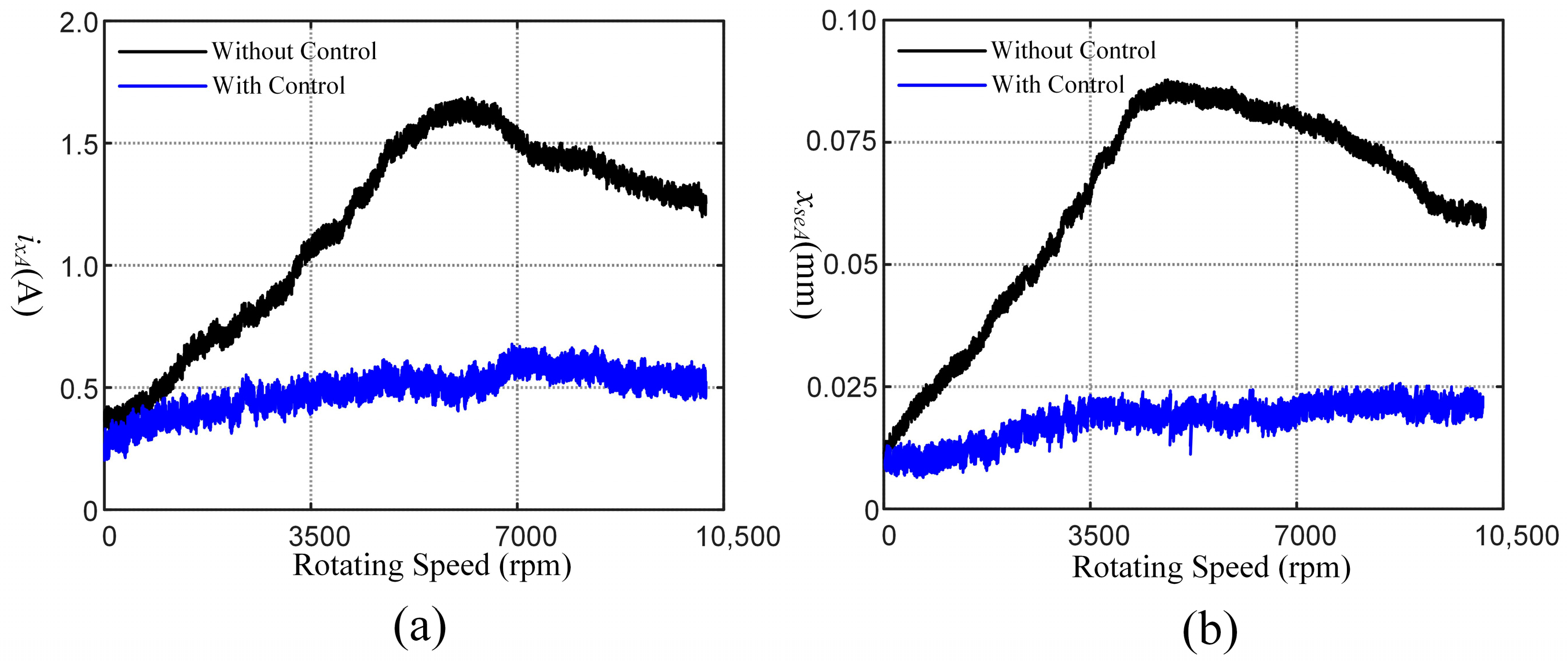
The overall control scheme’s validity is confirmed under the time-varying rotating speed. The initial iteration factor is 0.08. The rotating speed increases from 0 rpm to 10,500 rpm at an acceleration of 60 rpm· s 1 . Figure 13 shows the current and displacement vibration amplitudes with and without control. The amplitudes of current and displacement vibrations are significantly reduced after applying control. Moreover, the overall control scheme performs well in the rigid mode frequency region. Figure 11, Figure 12 and Figure 13 show much noise. Poor grounding or age of the test bench’s insulated cable may be to blame for signal noise. Noise may cause errors in the calculation of synchronous energy, thereby affecting the performance of the control algorithm. In the overall control scheme, we set multiple low-pass filters to reduce the impact of the noise on the AMB system.

5. Discussion

Firstly, the simulations show that the frequency estimator has a short response time and significant precision and robustness, which allow it to control the error within ± 0.05 Hz even in the presence of noise. Moreover, the experiments show that the frequency estimator has excellent tracking performance. Then, simulations and experiments verified the effectiveness and reliability of the overall control scheme to suppress the current and displacement vibrations. The simulation results show that the larger the initial iteration factor, the faster the algorithm converges, but when it exceeds the stability threshold, the algorithm becomes unstable. This is consistent with the asymptotic stability theory described in Section 3. The experimental results also confirm the effectiveness of the algorithm in the rotating speed range of 0–10,500 rpm. These results show that the control scheme proposed in this paper provides a new perspective on speed estimation, which further improves the performance of the AMB system and expands its application.

6. Conclusions

The control scheme proposed in this paper can effectively suppress displacement and current vibrations without the rotating speed sensor. The frequency estimator contains three modules, which has the advantages of a short response time, high precision and robustness, and significant tracking performance. The NAC algorithm takes synchronous DC components as the objective function and suppresses the current and displacement vibrations based on the periodic iteration strategy. In addition, the stability of the NAC algorithm is proved by the Lyapunov method. Finally, the simulation and experimental results demonstrate the effectiveness of the overall control scheme. However, the premise of the control scheme still assumes that the rotor is rigid. If the rotor speed is near the flexible region, the system will generate a phase delay, which will affect the performance of the proposed method. Therefore, the corresponding research work on vibration control in the flexible region will be further carried out in the future.

Author Contributions

Conceptualization, X.B. and N.M.; methodology, X.B. and N.M.; software, N.M. and X.B.; validation, X.B., N.M. and Z.S.; formal analysis, X.B.; investigation, X.B.; resources, Z.S. and L.S.; data curation, X.B.; writing—original draft preparation, X.B.; writing—review and editing, X.L. and Y.Z.; visualization, X.B.; supervision, Z.S.; project administration, Z.S.; funding acquisition, Z.S. and L.S. All authors have read and agreed to the published version of the manuscript.

Funding

This research was funded by National S&T Major Project of China, grant number No. ZX069; and The National High Technology Research and Development Program of China, grant number 2014AA052701.

Data Availability Statement

Not applicable.

Conflicts of Interest

The authors declare no conflict of interest.

References

  1. Dai, R.; Zhang, F.G.; Wang, H.J. Characteristics and Key Technical Issues of High-Speed Motors. Chin. J. Turbomach. 2019, 61, 59–66. [Google Scholar]
  2. Yin, H.; Liu, L. Progress of Active Magnetic Bearings in Compressors and Blowers. Chin. J. Turbomach. 2019, 61, 88–94. [Google Scholar]
  3. Numanoy, N.; Srisertpol, J. Vibration Reduction of an Overhung Rotor Supported by an Active Magnetic Bearing Using a Decoupling Control System. Machines 2019, 7, 73. [Google Scholar] [CrossRef] [Green Version]
  4. Zheng, L.; Nie, W.; Xiang, B. Vibration Analysis and Active Control of Rotor Shaft in Magnetically Suspended Air-Blower. Machines 2022, 10, 570. [Google Scholar] [CrossRef]
  5. Schweitzer, G.; Maslen, E.H. Magnetic Bearings: Theory, Design, and Application to Rotating Machinery; Springer: Berlin, Germany, 2009; pp. 15–36. [Google Scholar]
  6. Mystkowski, A. Mu-Synthesis for Magnetic Bearings of Flywheel. In PAMM: Proceedings in Applied Mathematics and Mechanics; WILEY-VCH Verlag: Berlin, Germany, 2009. [Google Scholar]
  7. Mystkowski, A.; Pawluszewicz, E. Nonlinear Position-Flux Zero-Bias Control for AMB System with Disturbance. Appl. Comput. Electrom. 2017, 32, 650–656. [Google Scholar]
  8. Zhao, Y.; Liu, X.; Yang, G.; Shi, Z.; Zhao, L. Analysis of the Relationship Between the Maximum Bearing Capacity of Axial AMB and the Rotational Speed Based on the Comprehensive Material Strength and Other Factors. Chin. J. Turbomach. 2020, 62, 53–58. [Google Scholar]
  9. Liu, L.; Wang, Y. On Nonlinear PID Control of Active Electromagnetic Bearing System with Variable Parameters. Chin. J. Turbomach. 2019, 61, 55–60. [Google Scholar]
  10. Zhao, Y.; Gong, H. Research on Recovery Strategy for the Horizontal AMB Rotor Drop Process. Chin. J. Turbomach. 2020, 62, 38–45. [Google Scholar]
  11. Chen, S.Y.; Lin, G.J. Robust nonsingular terminal sliding-mode control for nonlinear magnetic bearing system. IEEE Trans. Ind. Electron. 2011, 19, 636–643. [Google Scholar] [CrossRef]
  12. Chuhmann, T.; Hofmann, W. Improving operational performance of active magnetic bearings using Kalman filter and state feedback control. IEEE Trans. Ind. Electron. 2012, 59, 821–829. [Google Scholar] [CrossRef]
  13. Beltran-Carbajal, F.; Silva-Navarro, G.; Arias-Montiel, M. Active unbalance control of rotor systems using on-line algebraic identification methods. Asian J. Contr. 2013, 15, 1627–1637. [Google Scholar] [CrossRef]
  14. Jang, M.J.; Chen, C.L. Sliding mode control for active magnetic bearing system with flexible rotor. J. Franklin I. 2005, 342, 401–419. [Google Scholar] [CrossRef]
  15. Tung, P.-C.; Tsai, M.-T. Design of model-based unbalance compensator with fuzzy gain tuning mechanism for an active magnetic bearing system. Expert Syst. Appl. 2011, 38, 12861–12868. [Google Scholar] [CrossRef]
  16. Zheng, S.; Chen, Q.; Ren, H. Active balancing control of AMB-rotor systems using a phase-shift notch filter connected in parallel mode. IEEE Trans. Ind. Electron. 2016, 63, 3777–3785. [Google Scholar] [CrossRef]
  17. Peng, C.; Zhu, M.; Wang, Y.; Jiang, J. Phase-based video measurement for active vibration suppression performance of the magnetically suspended rotor system. IEEE Trans. Ind. Electron. 2021, 68, 1497–1505. [Google Scholar] [CrossRef]
  18. Xu, X.; Chen, S.; Zhang, Y. Automatic balancing of AMB systems using plural notch filter and adaptive synchronous compensation. J. Sound Vib. 2016, 374, 29–42. [Google Scholar] [CrossRef]
  19. Peng, C.; He, J.; Zhu, M.; Deng, Z.; Zhen, Z.; Liu, Q. Optimal synchronous vibration control for magnetically suspended centrifugal compressor. Mech. Syst. Signal Process. 2019, 132, 776–789. [Google Scholar] [CrossRef]
  20. Peng, C.; Zhu, M. A two-stage synchronous vibration control for magnetically suspended rotor system in the full speed range. IEEE Trans. Ind. Electron. 2020, 67, 480–489. [Google Scholar] [CrossRef]
  21. Herzog, R.; Buhler, P. Unbalance compensation using generalized notch filters in the multivariable feedback of magnetic bearings. IEEE Trans. Contr. Syst. Technol. 1996, 4, 580–586. [Google Scholar] [CrossRef]
  22. Vahedforough, E.; Shafai, B. Estimation and rejection of unknown sinusoidal disturbances using a generalized adaptive forced balancing method. In Proceedings of the 2007 American Control Conference, New York, NY, USA, 11–13 July 2007. [Google Scholar]
  23. Shi, J.; Zmood, R. Synchronous disturbance attenuation in magnetic bearing systems using adaptive compensating signals. Control Eng. Pract. 2004, 12, 283–290. [Google Scholar] [CrossRef]
  24. Turker, E.; Harvey, A. Improving active magnetic bearing system performance using recursive least square method. In Proceedings of the TENCON 2006—2006 IEEE Region 10 Conference, Hong Kong, China, 14–17 November 2006. [Google Scholar]
  25. Zhou, J.; Wu, H.; Wang, W.; Hu, Y.; Guo, X.; Song, C. Online unbalance compensation of a maglev rotor with two active magnetic bearings based on the LMS algorithm and the influence coefficient method. Mech. Syst. Signal Process. 2022, 166, 108460. [Google Scholar]
  26. Jiang, K.; Zhu, C. Unbalance compensation by recursive seeking unbalance mass position in active magnetic bearing rotor system. IEEE Trans. Ind. Electron. 2015, 62, 5655–5664. [Google Scholar]
  27. Mao, C.; Zhu, C. Unbalance compensation for active magnetic bearing rotor system using a variable step size real-time iterative seeking algorithm. IEEE Trans. Ind. Electron. 2018, 65, 4177–4186. [Google Scholar]
  28. Gong, L.; Zhu, C. Synchronous vibration control for magnetically suspended rotor system using a variable angle compensation algorithm. IEEE Trans. Ind. Electron. 2021, 68, 6547–6559. [Google Scholar] [CrossRef]
  29. He, Y.; Shi, L. Unbalance compensation of a full-scale test rig designed for htr-10gt: A frequency-domain approach based on iterative learning control. Sci. Technol. Nucl. Ins. 2017, 2017, 3126738. [Google Scholar] [CrossRef] [Green Version]
  30. Nonami, K.; Fan, Q.F.; Ueyama, H. Unbalance vibration control of magnetic bearing systems using adaptive algorithm with disturbance frequency estimation. JSME Int. J. 1998, 41, 220–226. [Google Scholar] [CrossRef] [Green Version]
  31. Yang, R.D.; Pei, W.Z.; Yang, Y.Q.; Deng, Z.Q.; Peng, C. A novel method for rotational speed observation of magnetically suspended high speed motor using quadrature phase-locked-loop. IEEE Sens. J. 2022, 22, 8604–8613. [Google Scholar] [CrossRef]
  32. Wu, H.T.; Zhou, J.; Zhang, Y.; Han, X.M. Adaptive auto balancing of magnetically suspended rotor based on second order generalized integrator frequency locked loop. Proc. CSEE 2021, 41, 1505–1514. [Google Scholar]
  33. Chen, Q.; Liu, G.; Han, B.C. Suppression of imbalance vibration in AMB-rotor systems using adaptive frequency estimator. IEEE Trans. Ind. Electron. 2015, 62, 7696–7705. [Google Scholar] [CrossRef]
  34. Li, J.L.; Liu, G.; Cui, P.L.; Zheng, S.Q. Suppression of harmonic vibration in AMB-rotor systems using double-input adaptive frequency estimator. IEEE Trans. Ind. Electron. 2022, 69, 2986–2995. [Google Scholar] [CrossRef]
  35. Bodson, M. Rejection of periodic disturbances of unknown and time-varying frequency. Int. J. Adapt. Control Signal Process. 2005, 15, 67–88. [Google Scholar] [CrossRef]
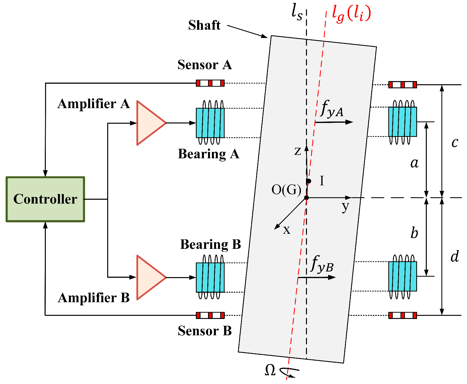
Figure 1. Diagram of the structure of the radial 4-dof AMB system.
Machines 11 00188 g001
Figure 2. Block diagram of the AMB system with mass imbalance.
Machines 11 00188 g002
Figure 3. Block diagram of the overall algorithm structure.
Machines 11 00188 g003
Figure 4. Rotating speed evaluation.
Machines 11 00188 g004
Figure 5. Flow chart of the frequency estimator.
Machines 11 00188 g005
Figure 6. Simulation result of the novel frequency estimator.
Machines 11 00188 g006
Figure 7. Noise immunity of the novel frequency estimator: (a) SNR = 20 dB; (b) SNR = 13 dB.
Machines 11 00188 g007
Figure 8. Simulation results of the NAC algorithm: (a) Displacement vibration elimination with different initial iteration factors; (b) Current vibration elimination with different initial iteration factors.
Machines 11 00188 g008
Figure 9. Experimental setup of the AMB system.
Machines 11 00188 g009
Figure 10. Experimental results of the frequency estimator.
Machines 11 00188 g010
Figure 11. Experimental results of displacement vibration elimination.
Machines 11 00188 g011
Figure 12. Experimental results of current vibration elimination.
Machines 11 00188 g012
Figure 13. Experimental results of the overall control scheme in full rotating speed range: (a) Current vibration amplitude without and with control; (b) Displacement vibration amplitude without and with control.
Machines 11 00188 g013
Table 1. Simulation parameters.
ParameterValueUnit
m 32.45kg
J t 0.88kg m 2
J z 0.05kg m 2
K s A = K s B −35,428.09 N m 1
K i A = K i B 18.35319 N A 1
K s e A = K s e B 30,000 V m 1
a 0.41m
b −0.39m
c 0.48m
d −0.47m
Disclaimer/Publisher’s Note: The statements, opinions and data contained in all publications are solely those of the individual author(s) and contributor(s) and not of MDPI and/or the editor(s). MDPI and/or the editor(s) disclaim responsibility for any injury to people or property resulting from any ideas, methods, instructions or products referred to in the content.