Article

Design of Quasi-Halbach Permanent-Magnet Vernier Machine for Direct-Drive Urban Vehicle Application

by
Walid Guendouz
1,2,*,
Abdelmounaim Tounzi
1 and
Toufik Rekioua
2
1
Arts et Metiers Institute of Technology, University of Lille, L2EP, Univ. Lille, Centrale Lille, Junia, ULR 2697-L2EP Lille, France
2
Laboratoire de Technologie Industrielle et de l’Information, Faculté de Technologie, Université de Bejaia, Bejaia 06000, Algeria
*
Author to whom correspondence should be addressed.
Machines 2023, 11(2), 136; https://doi.org/10.3390/machines11020136
Submission received: 30 November 2022 / Revised: 13 January 2023 / Accepted: 17 January 2023 / Published: 19 January 2023

Abstract

:
Removing the gearbox from the single-motor configuration of an electric vehicle (EV) would improve motor-to-wheel efficiency by preventing mechanical losses, thus extending the autonomy of the EV. To this end, a permanent-magnet Vernier machine (PMVM) is designed to ensure such operation. This machine avoids the high volume and large pole-pair number of the armature winding since its operating principle resembles that of a synchronous machine with an integrated magnetic gear. Therefore, such a structure achieves low-speed and high-torque operation at standard supply frequencies. From the specification of an urban vehicle, the required specification for direct-drive operation is first determined. On this basis, an initial prototype of a Vernier Machine with permanent magnets in the rotor that can replace the traction part (motor + gearbox) is designed and sized. This first prototype uses radial contiguous surface-mounted magnets and its performance is then analyzed using finite element analysis (FEA), showing a relatively high torque ripple ratio. The rotor magnets are then arranged in a quasi-Halbach configuration and simulations are performed with different stator slot openings and different ratios of the tangential part of the magnet in order to quantify the effect of each of these two quantities in terms of average torque, torque ripples and harmonics of the back-electromotive force at no load. Since the design and optimization of this motor is finite element-assisted, a coupling process between FEA Flux software and Altair HyperStudy is implemented for optimization. This method has the advantages of high accuracy of the magnetic flux densities and electromagnetic torque estimates, and especially the torque ripples. The optimization process leads to a prototype with an average torque value that meets the specification, along with a torque ripple ratio below 5% and a high power factor, while keeping the same amount of magnet and copper.

1. Introduction

In recent years, climate and energy issues have led to the unprecedented development of electric vehicles. Indeed, as transport is one of the sectors with high greenhouse gas emissions, the use of electric traction instead of combustion engines would make it possible to limit these emissions. This development also aligns with increasingly strong demand from users, which has led manufacturers to invest in various research projects to increase the reliability of vehicles while reducing their price. Within this broad context, the electric powertrain is a key point to meet the requirements of an efficient EV. The electric powertrain is usually a combination of an electrical and a mechanical subsystem. The electrical system consists of energy sources (batteries or fuel cells) to power receivers (one or more electric traction motors and auxiliaries). The mechanical system is usually a clutch, a transmission and a differential.
Today, the electric vehicle powertrain is the one that is experiencing the most rapid technological innovation and change. The configuration of the architecture depends on the required size and application of the electric vehicles, knowing that the main characteristics that must be fulfilled are the performance, compactness, weight and cost of the EV. There can be many configurations of drive systems, as shown in [1,2,3,4]. Two main configurations of the powertrain can be identified: the “distributed” and “single-engine” configurations [5].
The first configuration completely eliminates mechanical transmission parts such as the mechanical drive shaft and differential, and is driven directly by gearless motors housed in the wheel hubs, including power electronics. The differential action required for cornering is achieved electronically by the two electric motors, but this obviously requires as many electronic converters as motors, and there is a risk of accidents due to sharp cornering and uncontrolled braking [6,7,8,9]. There are many publications on such gearless motor-wheel drive systems that use external-rotor synchronous magnet motors [10] manufactured for high-torque and low-speed applications, hence the design complexity and, therefore, the price of the electric motor [11]. The increase in wheel mass due to the motors also constitutes a problem since this causes high friction with the ground. A large amount of energy is then lost in the form of heat, leading to rapid tire wear.
The second configuration uses a single traction machine that is placed either with the driveshaft or without the driveline placed directly on the front or rear axle. This structure is the most-used in EV as it prevents weight and bulk. It generally uses high-speed machines [12,13,14] but presents the disadvantages of gearing in terms of mechanical transmission loss, acoustic noise and the need for regular lubrication [15]. One solution to the latter is to switch the engine and the gearbox, with a single or multiple gear, with a single engine directly feeding the wheels via the differential. This eliminates mechanical losses due to gear friction in the gearbox, thus increasing the efficiency of the configuration. This solution has mainly been studied using permanent-magnet synchronous machines (PMSM) with large numbers of poles, and hence, a large diameter, because of the need for high torque at relatively low speed [16,17]. However, these characteristics would also be fulfilled by Vernier permanent-magnet machines (PMVMs) with reduced diameters. These structures are well known for their low-speed and high-torque operation at standard supply frequencies [18,19] while avoiding high pole pairs of the armature winding. Indeed, their operating principle is equivalent to that of PMSM, integrating a magnetic gear, and thus, increasing the torque [20]. In [21], the authors show that PMVM can reach almost three times that of an equivalent conventional synchronous machine with the same current and volume. Some of these machines have already been used as in-wheel direct drive [22]. In [23], a new structure with a double stator and double rotor for in-wheel application has been studied and analyzed to improve the torque density and the torque ripples. However, such a machine remains quite complicated to manufacture. In a previous study [24], different prototypes of PMVM with internal rotors were studied, showing interesting performance in terms of power factor and average torque, but the torque ripple ratio remained of high value. One solution to reducing this torque ripple consists of skewing the PM of the rotor [25], but this has the disadvantage of reducing the average torque. Another solution could be the use of rotor topologies with U-shaped and V-shaped magnets [26,27], but this is still complex to realize. Lastly, Halbach matrix magnets [28] can also be used to reduce the torque ripple. In addition, this configuration reduces the flux leakage between the PM poles, thus slightly increasing the torque density.
The present work deals with the study of an inner-rotor PM Vernier machine with a quasi-Halbach configuration of the magnets. The effects of the tangential part with respect to the rotor pole pitch on the machine performance (average torque and ripple rate) are evaluated via numerical modeling on the basis of finite element analysis (FEA). Based on an analytical approach with radial PM magnetization, a prototype is first designed and sized according to the specifications of an urban traction application. The rotor magnets are then arranged in a quasi-Halbach configuration and simulations are carried out with different stator slot openings and different ratios of the tangential part of the magnet in order to quantify the sensitivity effect of these two variables in terms of average torque, torque ripples and harmonics of the back-electromotive force at no-load. As the design and optimization of this motor are finite element-assisted, a coupling process is carried out between FEA Flux software and Altair HyperStudy for direct optimization using the GA single-objective algorithm [29]. This method has the advantage of the magnetic flux densities and electromagnetic torque estimates, and especially the torque ripples, being more accurate. The aim is to verify whether it is possible for the same amount of magnet and copper to obtain a structure that combines high torque with low ripple and sinusoidal no-load electromagnetic voltage.
This paper is organized as follows. The second part is devoted to an introduction of the operating principle of the PM Vernier machine, followed by the relationships between the pole pairs and the number of stator teeth to be respected. Then, a prototype of an internal-rotor PMVM for a direct-drive electric vehicle is designed on the basis of a given urban vehicle specification. The topology and dimensioning of the designed prototype with joined magnets are validated through the results obtained using a 2D finite element (FE) model. On the basis of this first prototype, the rotor magnets are divided into tangential and radial parts to obtain a quasi-Halbach configuration. Different ratios of this subdivision, along with the stator slot opening, are then evaluated in terms of the average torque and ripple rate, on the one hand, and the first, third and fifth harmonics of the no-load electromotive force, on the other hand, as well as the cogging torque and the power factor, in order to analyze the sensitivity of each parameter on the different motor performances. Lastly, we perform GA mono-objective optimization, taking the torque ripple ratio as a constraint to maximize the average torque, which is the objective function.

2. Machine Principle

In the PM Vernier machine, electromagnetic energy conversion is performed thanks to the interaction of the armature magnetic field of the ps pole pairs with that of the rotating magnets of the pr pole pairs. As the pole-pair numbers of the two magnetic fields are different, the variation in the air gap permeance due to the Ns stator slots is of great importance. Indeed, it modulates the two fields so that they can interact. This can be achieved through an adequate choice of the pole pairs and stator slot numbers.
Under the assumption of very high permeability of the magnetic material, the whole magnetic energy Wem of a PM Vernier machine is located in the only airgap and can be expressed as follows:
W e m = 1 2 0 2 π Ω e 2 ( θ s , θ ) P ( θ s ) d θ s
Where θ s represents a given position in the airgap with respect to a fixed stator axis and θ is the relative position of the rotor with respect to the stator. P represents the air gap permeance, whose expression is given by:
P ( θ s ) = P 0 + j = 1 P j s   ( j N s θ s )
where P0 and Pjs are coefficient functions of the geometric parameters of the airgap, and Ωe is the magnetic potential difference. It is constituted by the sum of the magnetomotive force (mmf) of the armature windings εa supplied by balanced three-phase currents and that of the PM, ε P M :
Ω e = ε a + ε P M
The FFT of these mmfs can be expressed as follows:
ε a = i = 0 3 π n I m a x ( 2 i + 1 ) ( 1 ) i K b i cos ( ω t ( 2 i + 1 ) p s θ s ) ε P M = m = 0 4 π A ( 2 m + 1 ) ( 1 ) m K b m cos ( 2 m + 1 ) p r ( θ s θ )
where n is the number of armature winding conductors, Imax is the maximal value of the current and ω is its electric pulsation. Additionally, A represents the maximal value of the square mmf due to the permanent magnets.
The development of relation (1) leads to several terms of which only a few are functions of the rotor position θ and can thus generate an electromagnetic torque.
T   = W em θ  
Only terms with functions of θ are of interest.
When analyzing the different terms of the energy whose development is given in Appendix A, we reach the following conclusions:
-
The integral of the two first terms leads to a constant value. The latter is independent of θ, and thus, is without any torque generation. In fact, this constitutes the magnetizing energy of the machine.
-
Terms that are cosine functions of θs whose integrals range from 0 to 2π are equal to zero.
-
The three terms that are functions of θs and θ can potentially generate torque. As the energy conversion is such machine should be based on the interaction between the two fields, the integrals of these terms are canceled by choosing:
N s 2 p r N s 2 p s p s p r
-
For the last three terms that are functions of θs and θ, each of them can generate an electromagnetic torque through the interaction of both magnetic fields. This can be achieved by choosing the following relationship between pr to ps and Ns [30]:
N s = | ± ( p r ± p s ) |
This leads to a constant average torque when the rotor is rotating at a speed Ω .
Ω = ω p r = 2 π f p r
The choice of the values of pr to ps and Ns depends on the different constraints, such as the link between Ns and ps depending on the nature of the armature windings to be used, or the rotor speed depending on the supply frequency. Of course, once the values of pr to ps and Ns are chosen, only one term will generate torques, while the integrals of the two others will be equal to zero.
The condition Ns = pr + ps leads to the magnetic armature field rotating in the same direction as the rotor, while the conditions Ns = prps and Ns = pspr make them rotate in opposite direction.
Finally, the Vernier reduction coefficient K V , which is the ratio of the number of pole pairs in the stator and the rotor, is:
K V = p s p r

3. Motor Design

3.1. Specifications of the Application

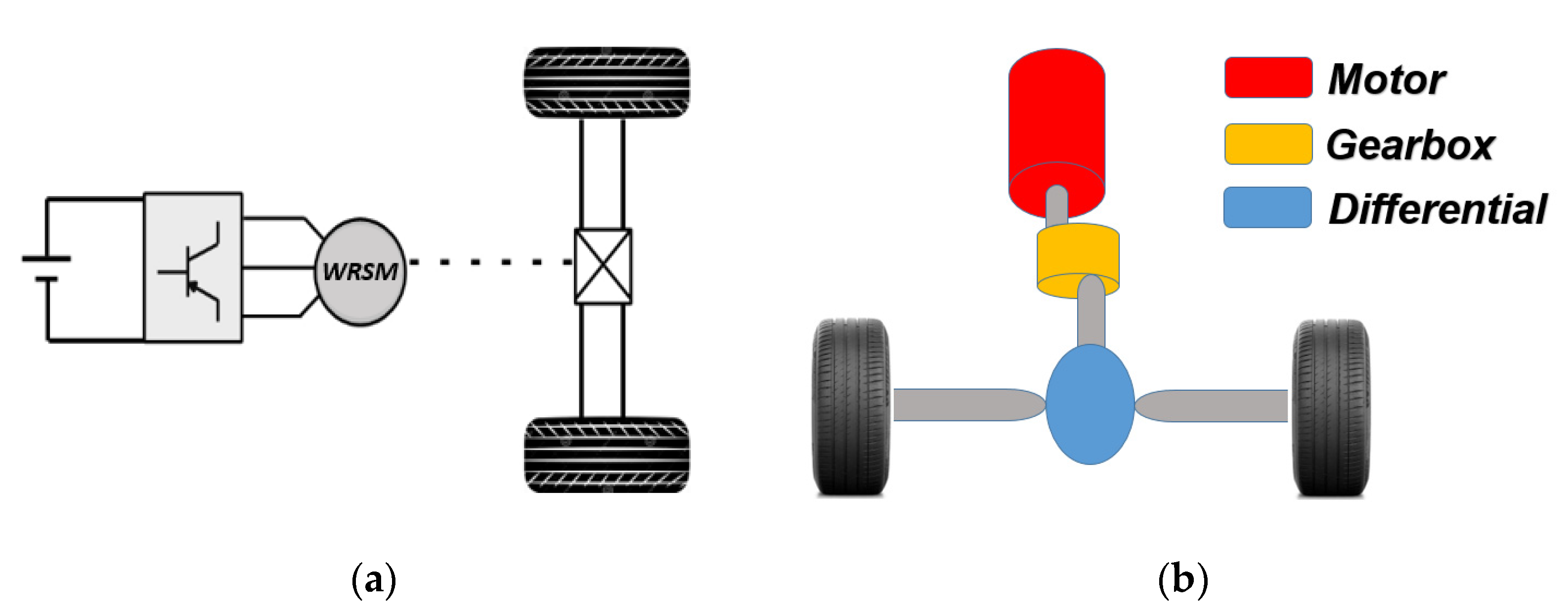
The powertrain used as a reference for this work is that of a small electric passenger vehicle, the Renault ZOE Q90 (Figure 1), which is the most popular vehicle currently sold in Europe. Figure 2 illustrates the electrical and mechanical components of the powertrain of the vehicle. The electrical part consists of a battery connected to an inverter that supplies a wound-rotor synchronous machine (WRSM). The shaft of the machine drives the wheels through a gearbox and differential. The main vehicle specifications are given in Table 1, while the characteristics of the Q90 motor used are summarized in Table 2.
To design a PMVM prototype that can meet the requirements of the traction part (motor + gearbox) of the ZOE in the context of a direct-drive application, the specifications of the prototype should first be distinguished from those of the actual solution. Using data given in both Table 1 and Table 2, including the ratio and efficiency of the gearbox, the rated torque and speed of the prototype to be sized can be obtained. These are depicted in Table 3, along with its other specifications.

3.2. Design of the Prototype

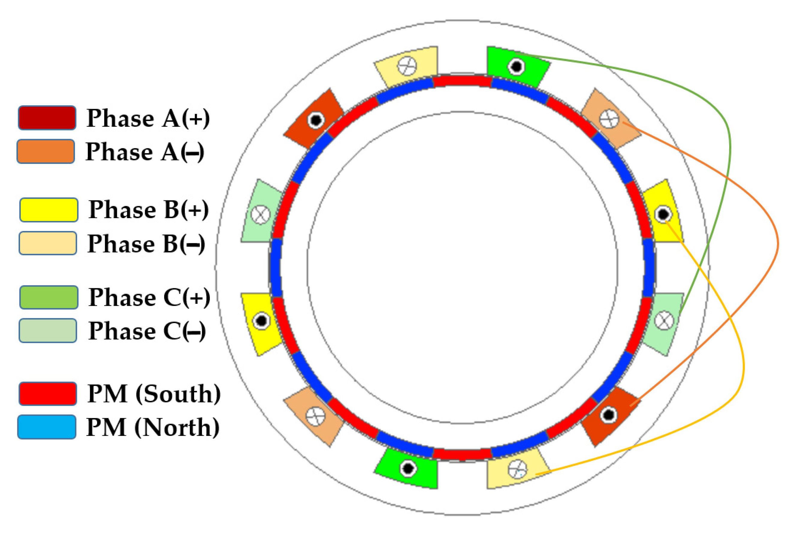
From the value of the base speed chosen (360 rpm) while respecting both relations (6) and (7) and avoiding a high supply frequency (f = 60 Hz), we end up with pr = 10, which corresponds to 20 alternate permanent magnets mounted on the rotor surface. Then, the values of ps and Ns are taken to be equal to ps = 2 and Ns = 12, respectively, with q = 1 slot per pole and per phase in the case of a three-phase machine with distributed windings (DW). A generic cross-section of the PMVM prototype is shown in Figure 3.
Since the PM Vernier machine is a synchronous structure, the geometric dimensioning of the prototype is then achieved by adopting a classical approach based on the volume of the air gap D 2   × L (D being the outer rotor diameter and L the active length) through the value of the T r a t e d :
T r a t e d = 1 2 × F t × D 2 × L × π        
where F t is the tangential magnetic pressure.
Then, once the rated voltage value is chosen, the number of turns per slot of the armature winding (ns) can be determined through the following relation:
n s   = I × S s l o t J × K f
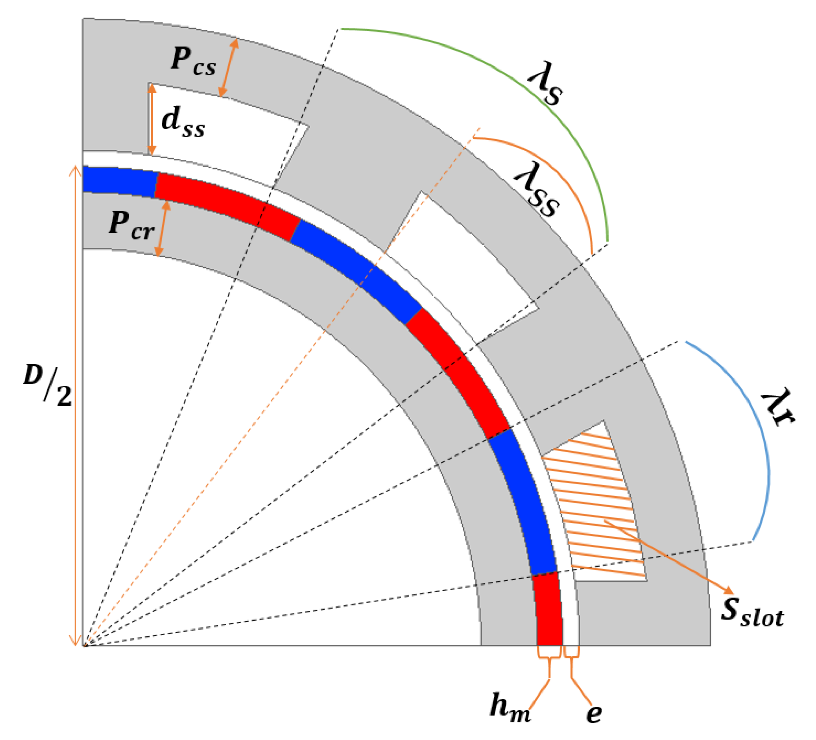
where J is the current density and   K f represents the fill factor. I is the rated RMS current and the   S s l o t represents the stator slot area. Let d s s   be the depth of the stator slot and e the airgap thickness; the S s l o t is expressed as:
S s l o t = ( D / 2 + e )   ×   λ s s   ×   d s s
where the stator slot pitch is defined by:
λ s = 2 π N s
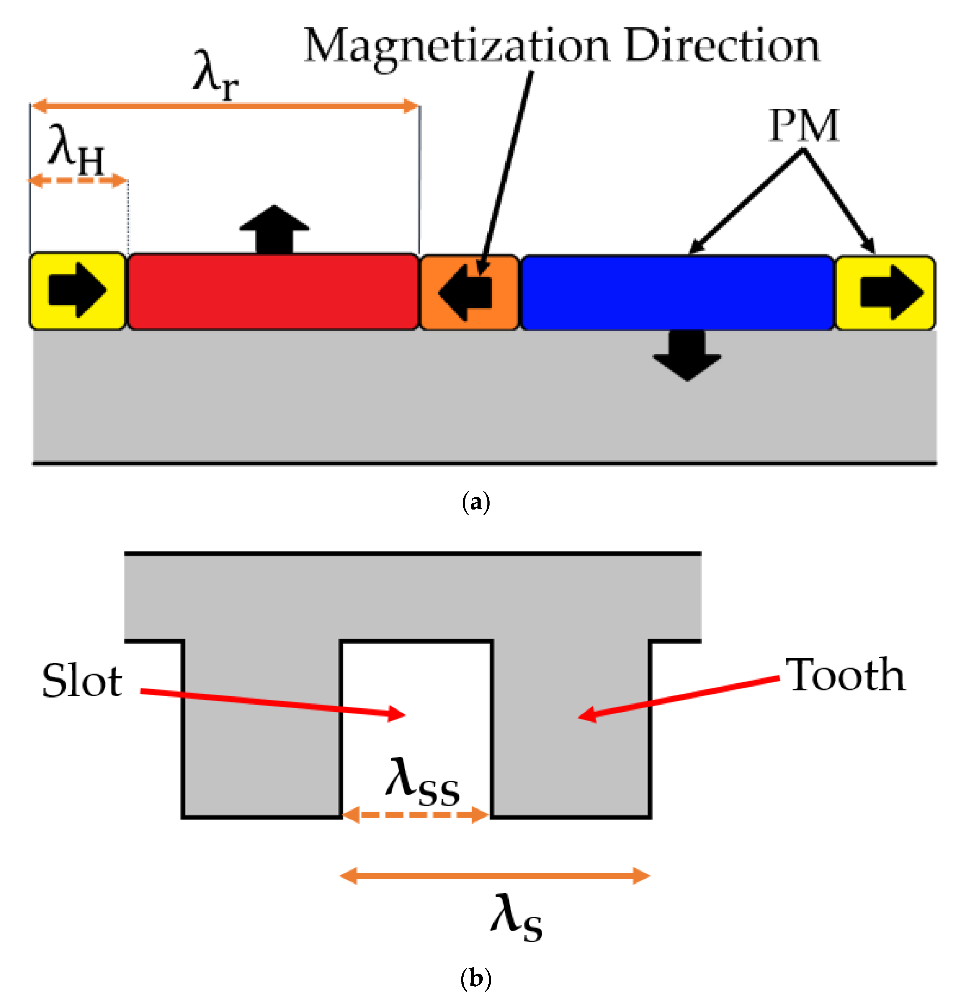
and λ s s   is the ratio of stator slot opening (as shown in Figure 4):
λ s s = β × λ s
Otherwise, the rotor pitch angle λ r is defined as:
λ r   = π p r
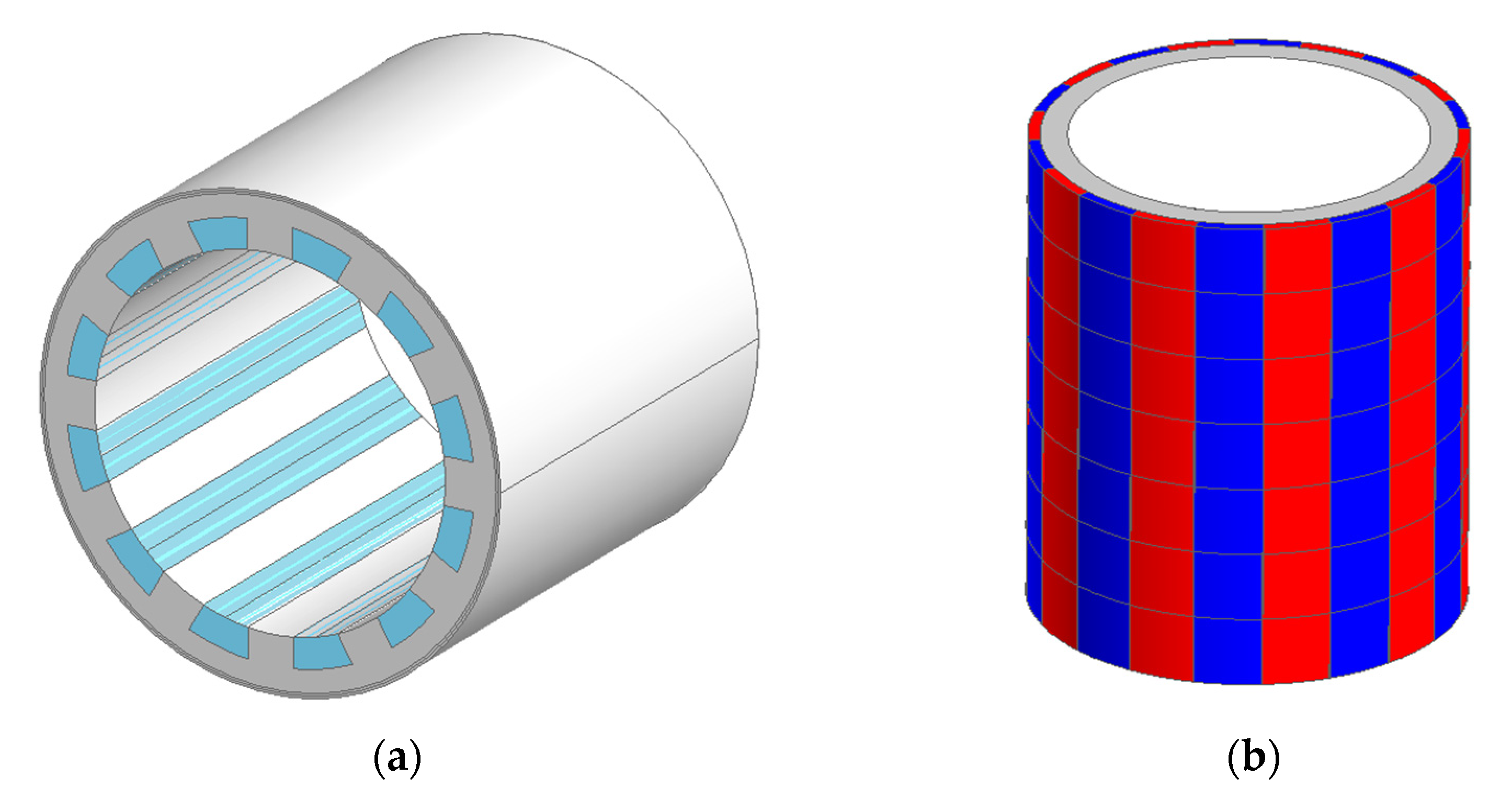
The first prototype is sized with contiguous magnet configuration and a ratio of stator slot opening to stator pitch λ s s / λ s equal to 50%. Figure 5 shows a view of the stator and rotor of the prototype, and its main characteristics are given in Table 4.
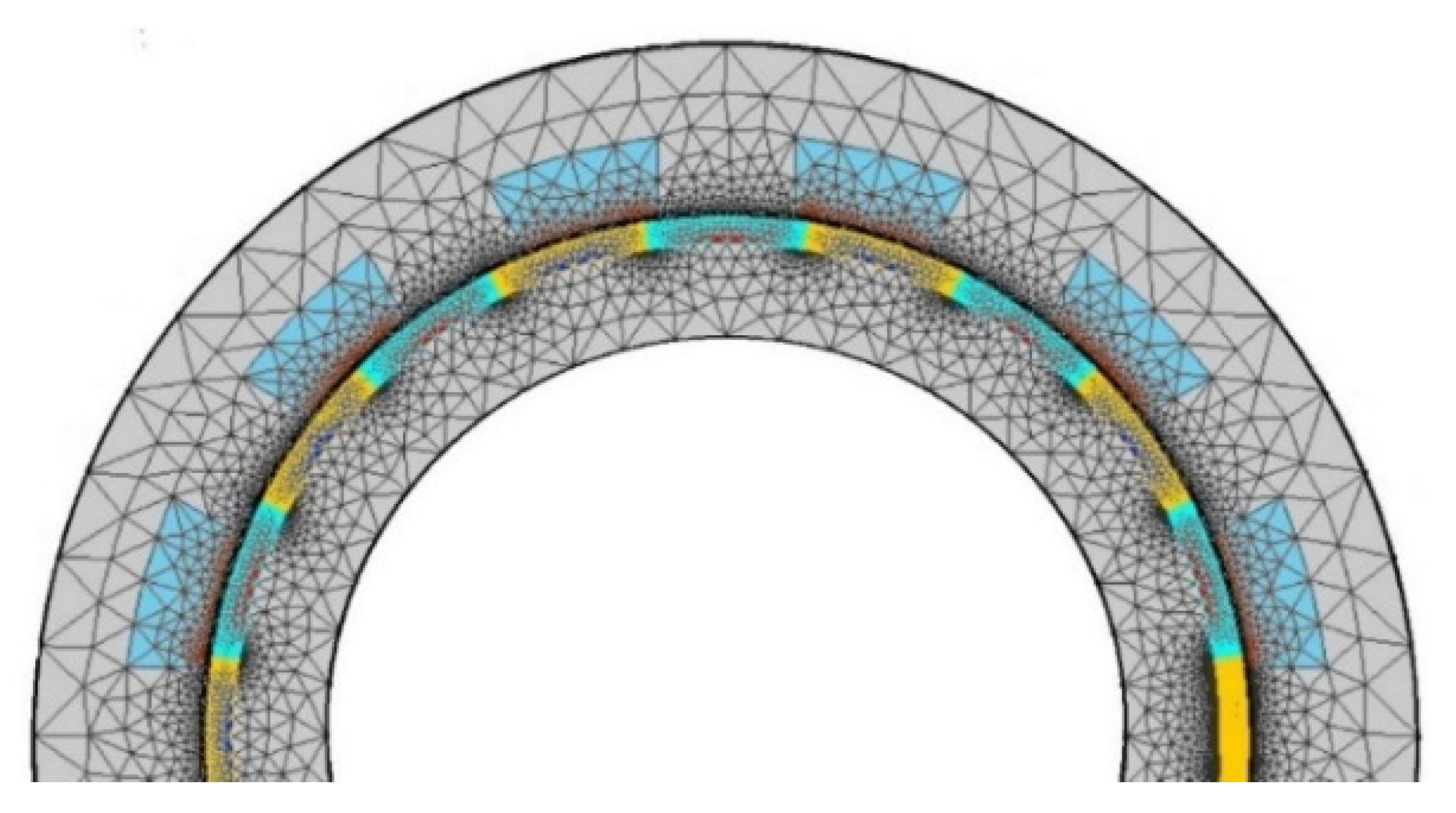
Different calculations were conducted on the designed prototype at no load and under rated load conditions using Flux 2D software. In order to limit the number of unknowns, and thus, the calculation time, only a partial model (half machine) is built. Figure 6 shows the model of the PMVM machine used (143,426 nodes).
Figure 7a depicts the magnetic flux density distribution at no load in the cross-section of the prototype. It clearly resembles a 2-pole-pair machine even though the rotor has 10 pole pairs. Figure 7b presents the electromagnetic torque vs. time when the machine is supplied by the rated three-phase currents at the rated frequency while the rotor rotates at the base speed (360 rpm).
It can be shown that the average torque value (1055 Nm) almost meets the specification of the application. However, the torque ripple ratio is quite high (14.08%), which is unsuitable for such an application. An optimization process must thus be used in order to reduce it.

3.3. Parameters to Optimize the PMVM

From relations (1), (2) and (3) of energy, it can be seen that certain structural parameters will affect the magnetic energy, and hence, the output performance of the motor. To reduce the harmonics of the no-load EMFs and/or the torque ripples, the simplest solution consists of skewing the stator or the rotor by a given angle. This is widely used in PM synchronous machines. However, such a solution does not seem appropriate in the case of the PM Vernier machine since it would decrease the magnitude of the air gap reluctance variation, which is the basis of the electromagnetic conversion in these machines. The remaining possibilities that can be used to optimize the PMVM are variation in the stator slot opening, along with the rotor magnet opening. However, for the latter, this will induce a reduction in the magnet amount, which would reduce the EMF magnitude. Quasi-Halbach configuration of the permanent magnets could be a much more suitable solution. Adding to the ratio β = λ s s / λ s of the stator slot opening, the ratio α = λ H / λ r of the tangential part of a magnet λ H to the rotor pole pitch λ r   ( see Figure 8) will then be two quantities that have non-negligible effects on the average value of the electromagnetic torque, its ripples and the harmonics of the no-load EMF.

4. Sensitivity Analysis of the Design Parameters

To study the impact of these two parameters on the machine performance, a sensitivity analysis is conducted by varying only one of the two variables within the ranges given in Table 5, which will thus define the limits of the optimization domain. Studies are carried out, at no load and at a rated load for different values of these ratios, while keeping the same amount of magnet, mechanical air gap and stator yoke thickness and taking into account the non-linear behavior of magnetic materials. Furthermore, for each case study, the power factor of the structure is also calculated.

5. Study at No Load

5.1. Impact of Ratio Slot Opening

Using 2D FEM, simulations are first carried out at no load and at a rated speed (360 rpm) while varying only β and keeping α = 0%. Figure 9a shows the obtained no-load EMF vs. time for different values of β, and Figure 9b their harmonic contents.
From Figure 9, it can be seen that the ratio of stator slot opening to stator pitch has a slight effect on the magnitude and waveform of the back-EMF, whose highest value is reached for a slot opening ratio between 45% and 50%.
For the same slot opening ratios, Figure 10 presents the cogging torque versus the rotor position for 6 degrees, which constitutes the GCD of the rotor pole opening and stator pitch.
Unlike the case of the back-EMF, Figure 10 and Figure 11 show that the ratio of the stator slot opening has a significant effect on the cogging torque. The latter varies from 107 Nm for β around 50% to 435 Nm for β between 40% and 45%.

5.2. Impact of Permanent-Magnet (PM) Halbach Arrangement

As for the stator slot opening ratio, calculations have been are carried at no load for different ratios of the tangential part of a magnet to the rotor pole pitch while keeping β = 50%.
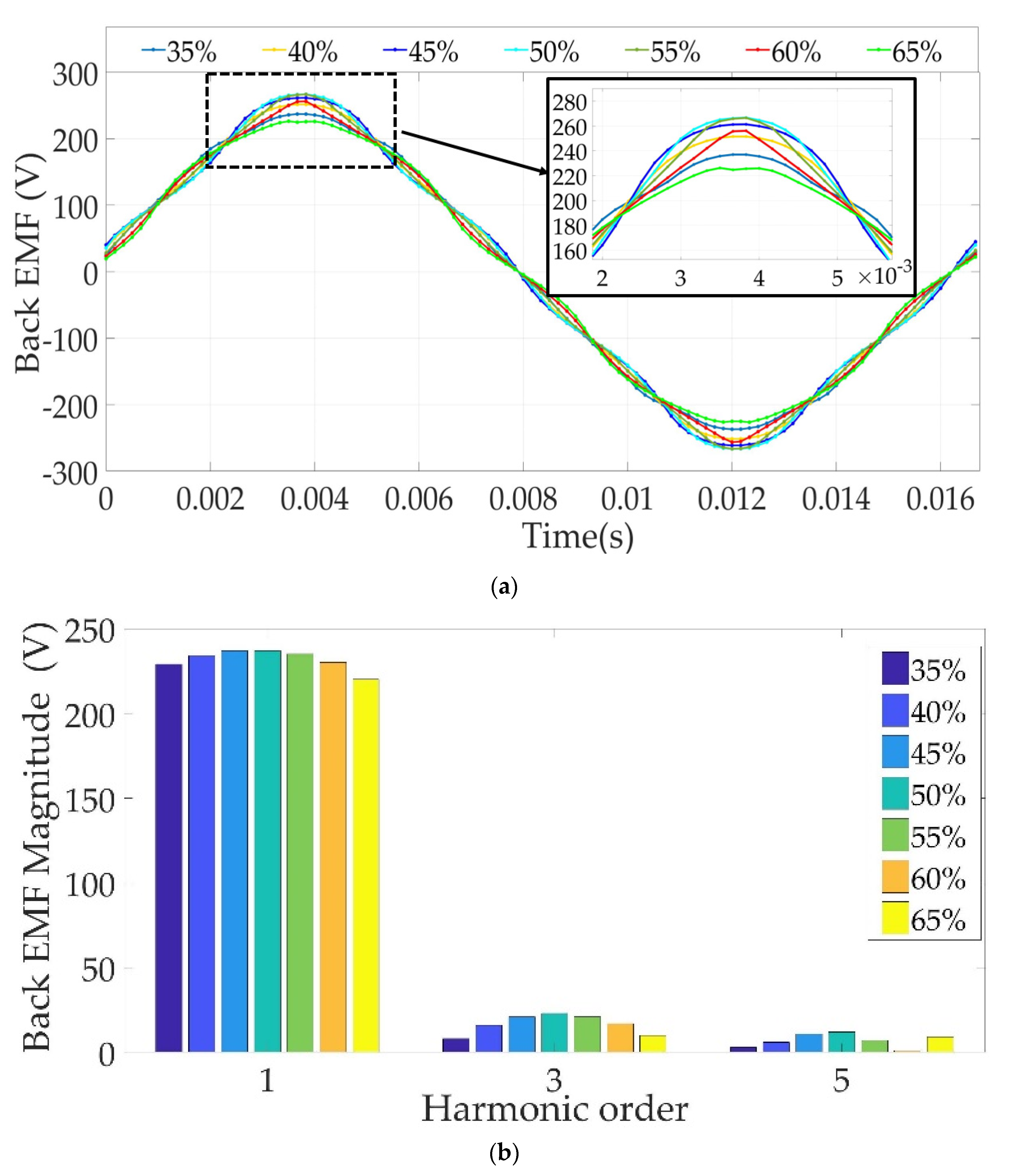
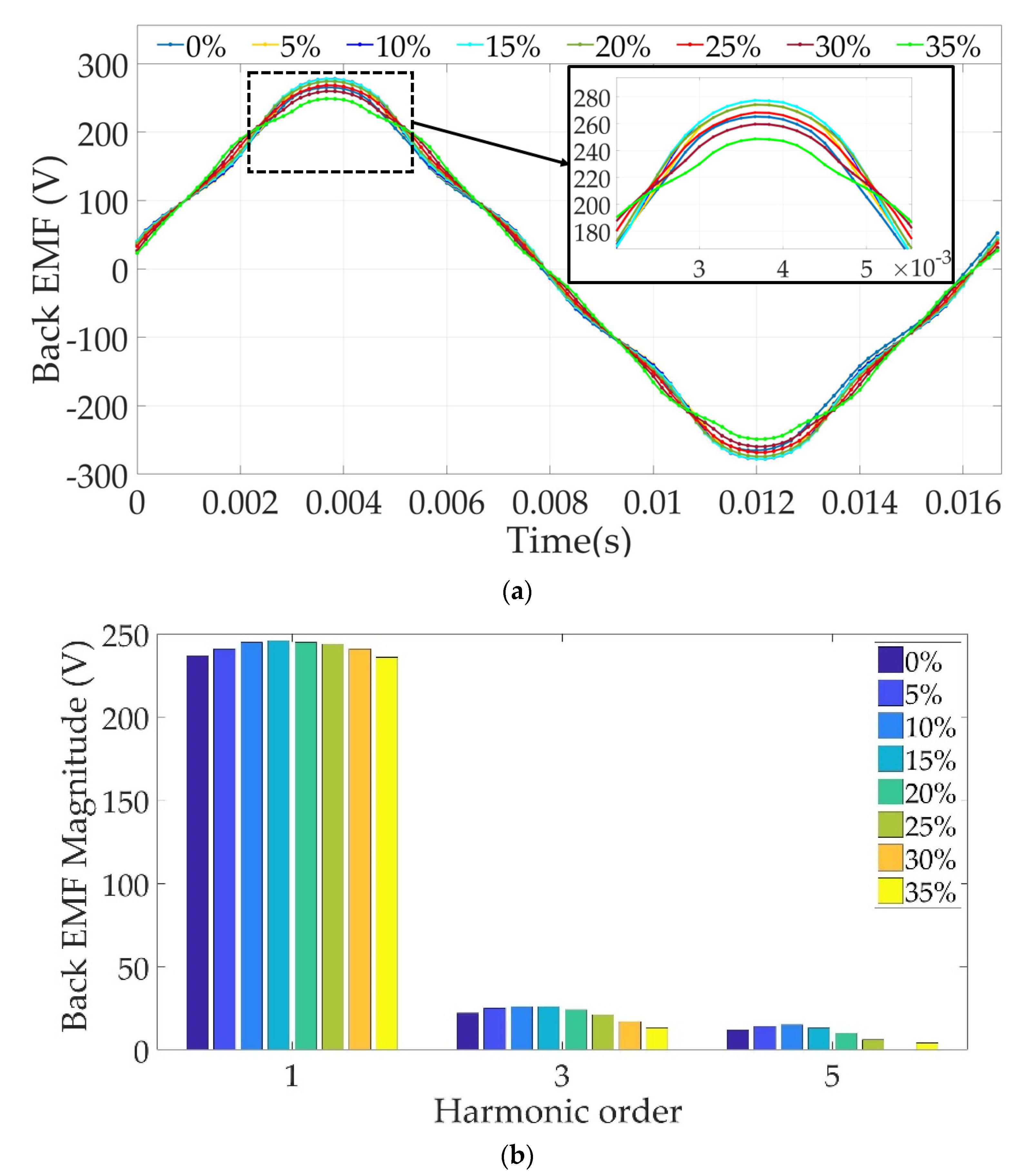
Figure 12a presents the EMF vs. time for the different values of α. As in the previous case, the latter has a limited effect on the magnitude of the back-EMF like with the first two harmonics, as shown in Figure 12b.
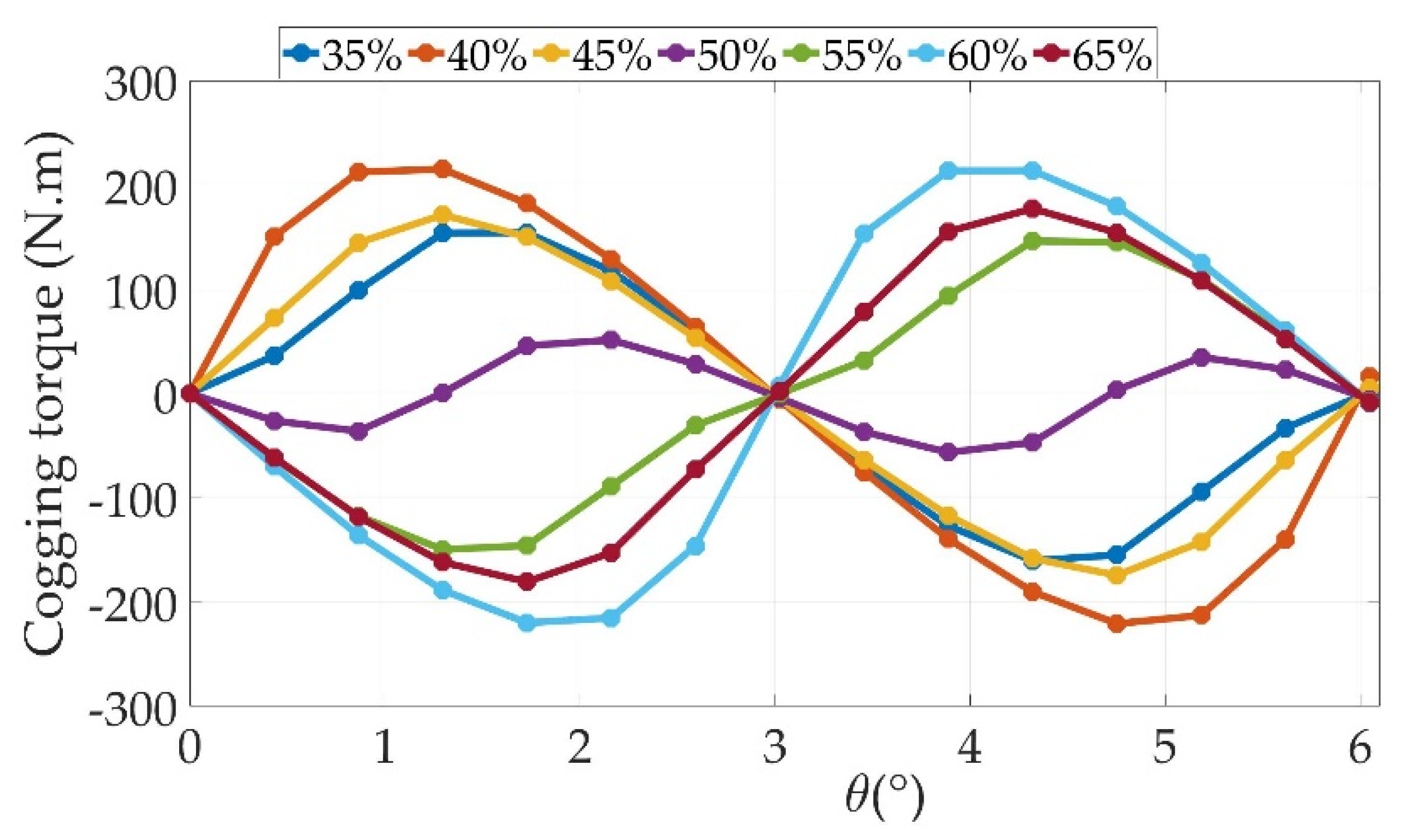
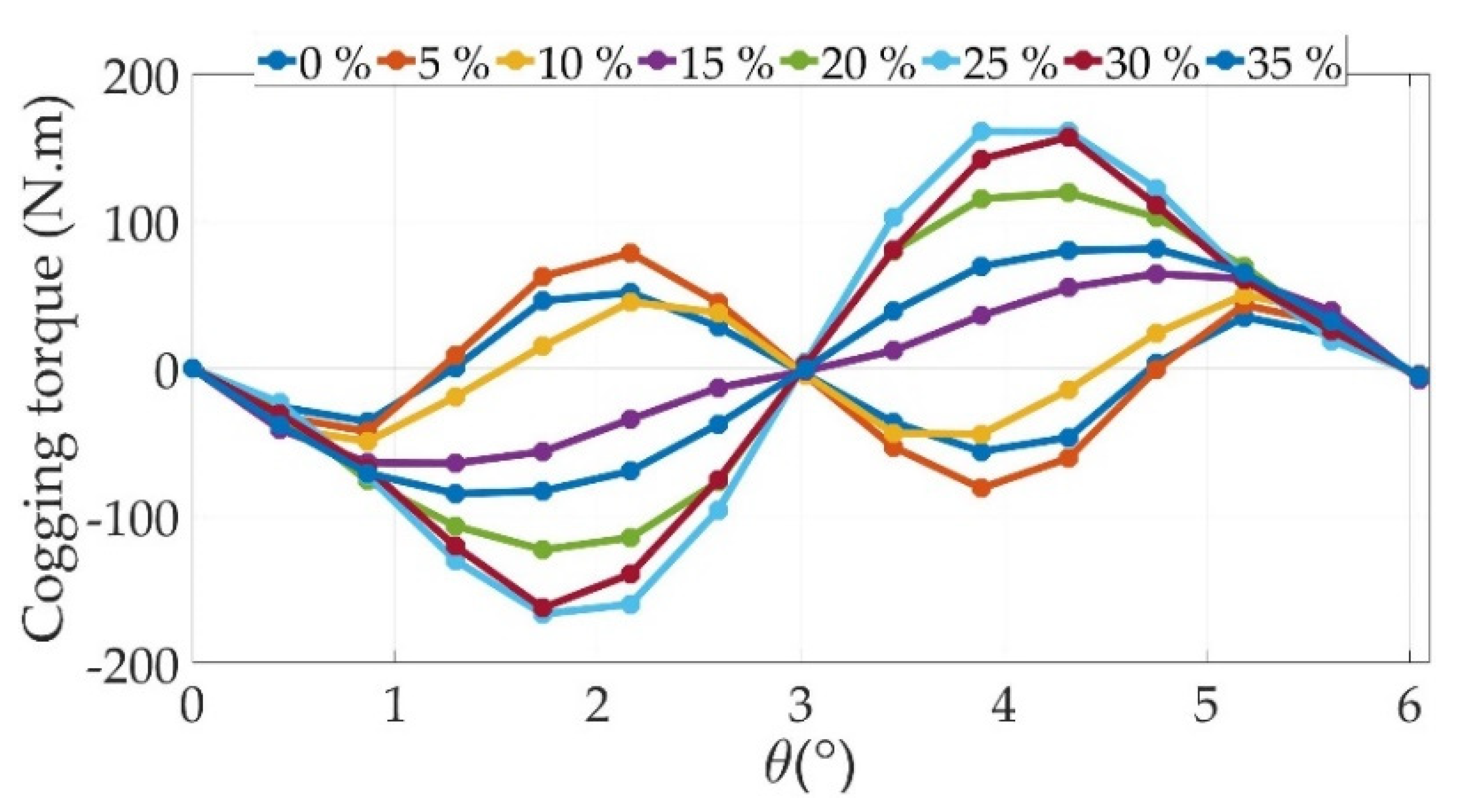
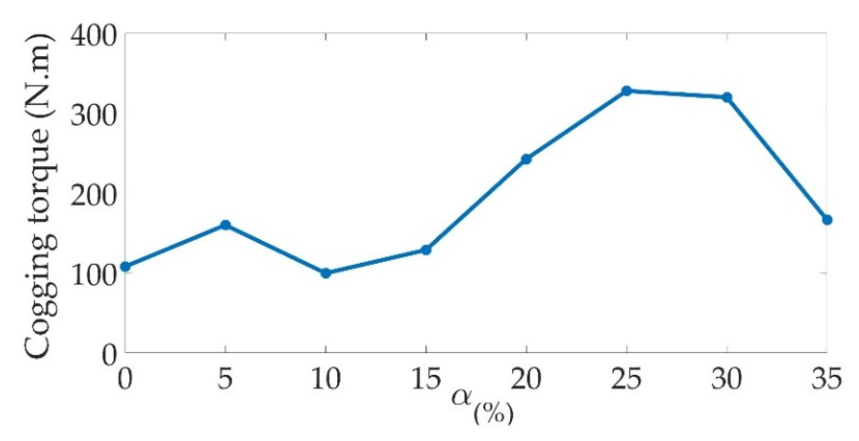
Regarding the cogging torque, α has an effect almost as significant as that of the stator slot opening ratio (variation from 99 Nm to 327 Nm), as can be seen in Figure 13 and Figure 14, which present the cogging torque vs. the rotor position and its peak-to-peak amplitude for different values of α, respectively.

6. Study at Load

Simulations are also conducted under rated-load operation. The armature windings are then supplied via three-phase balanced currents of the rated magnitude using the shift phase, which insures the highest average value of the torque at the rated speed. Furthermore, since the power factor p f of the PM Vernier machines constitutes a sensitive quantity, it is determined for each case from the maximal torque operating with I d = 0 and I q = I m a x using the following relation [31]:
p f = 1 1 + ( I q X q / E 0 ) 2
where E 0 is the RMS value of the no-load back-EMF, which is considered along the q-axis; I q represents the component of the armature current along the same axis; and X q is the reactance of the armature windings along the q-axis, knowing that ( X d =   X q =   X ).

6.1. Impact of Ratio Slot Opening

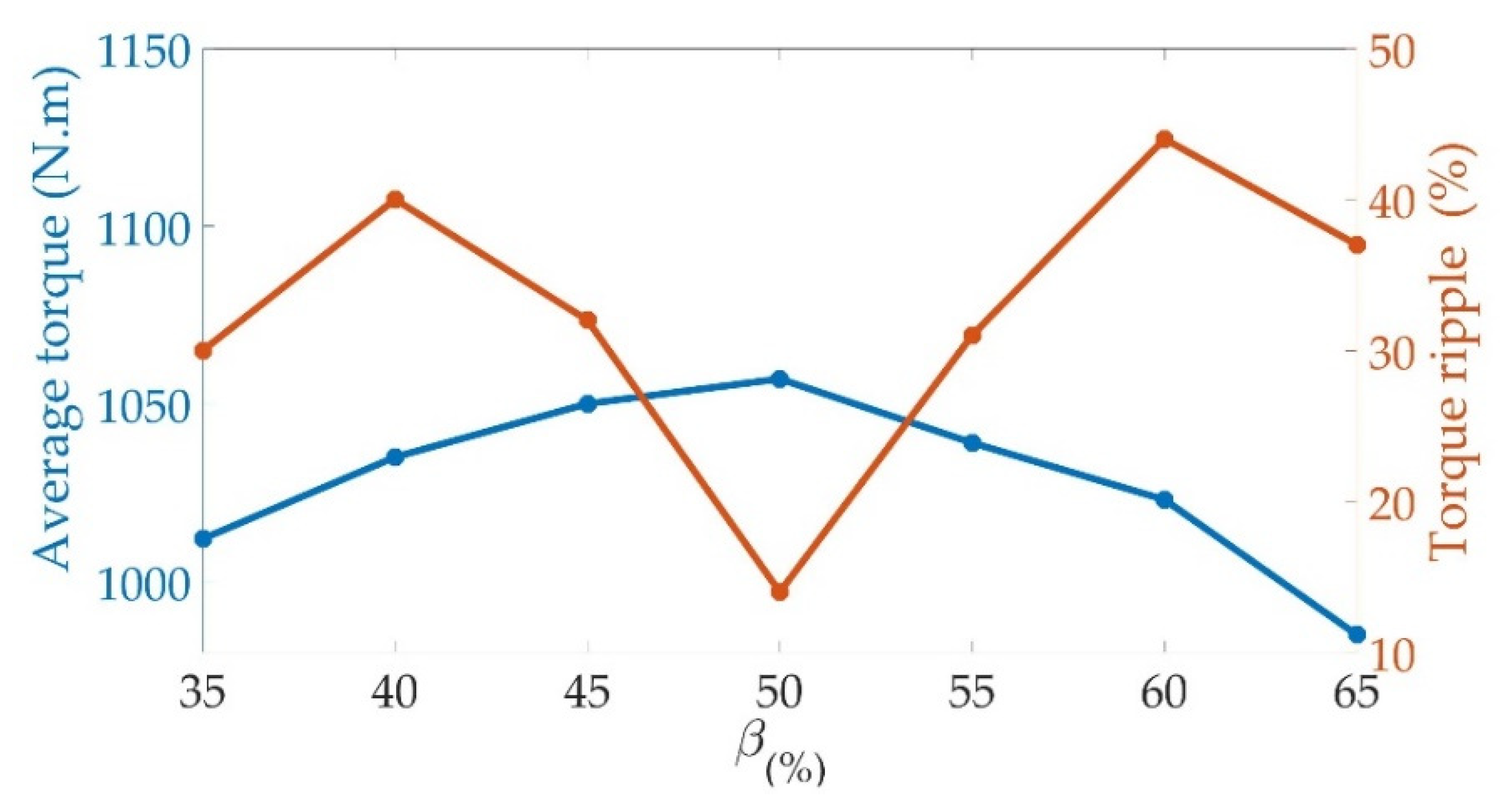
The results for different values of β given in Figure 15 show that the average value of the rated electromagnetic torque varies with respect to the ratio of the stator slot opening, reaching a maximal value for β = 50%. On the contrary, the torque ripple ratio presents the lowest value at about the same percentage (see Figure 15). These two quantities, thus, are very sensitive to the stator slot opening ratio.
The power factor, meanwhile, varies monotonically, increasing as a function of the stator slot opening and reaching an interesting value slightly higher than 0.85 at β = 65% (see Figure 16).

6.2. Impact of Permanent-Magnet (PM) Halbach Arrangement

Through the results shown in Figure 17, it can be seen that the ratio of the tangential part of a magnet to the rotor pole pitch has an effect that is slightly more important on the average torque than the stator slot opening. On the other hand, it has a much less significant effect on torque ripples since the torque ripple ratio presents the lowest percentage values when α < 15%.
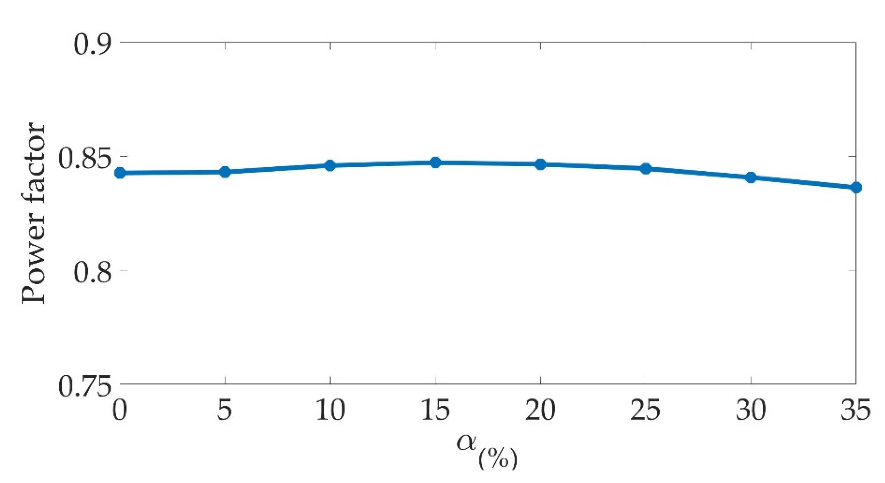
The effect is even less important on the power factor, as can be seen from the results depicted in Figure 18. Indeed, the latter remains practically constant over the entire variation range of α.

7. Optimization of the Prototype

Further to the results obtained in the sensitivity analysis, each of the two quantities, i.e., α and β, has its impact on the variables studied. It is worth mentioning that these impacts are not necessarily similar regarding each of the studied variables of interest and their interaction would be quite difficult to predict. Therefore, an optimization approach in which both quantities are varied has to be carried out.

Design and Optimization Method

HyperStudy is a multidisciplinary design study and optimization software for engineers and designers. This software proposes different optimization approaches (DOE, Fit, Optimization and Stochastic), thus making it a very interesting way to efficiently study the design of an electric machine when coupled to an FE model such as Flux 2D.
As depicted in Figure 19, in such coupling between the two software packages, HyperStudy will modify the values of the selected prototype input parameters (geometrical or physical) in specified ranges, leading to different prototypes that are then modeled and studied using Flux 2D. HyperStudy automatically retrieves the results of the selected output parameters from Flux to find the optimal values with respect to the specific objectives and constraints. This procedure can be conducted using different optimization algorithms. In the present study, we chose the GA (Genetic Algorithm) to optimize the quasi-Halbach PMVM since it is one of the most commonly used optimization strategies. Indeed, it is quite easy to implement and it allows for a relatively exhaustive investigation of the search space, which makes it very useful for dealing with our optimization problem.
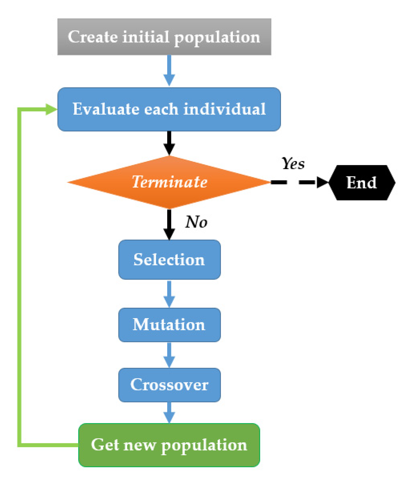
GA starts with the random creation of a population of designs called initial generation. Each individual is scored according to its adaptation to the problem, and then, a selection is made within the population to make the group evolve and converge towards the solution of the problem. According to the flowchart in Figure 20, the optimization algorithm is structured as follows:
-
Randomly generate the base population.
-
Evaluate each individual and score it according to its adaptation to the problem.
-
Select the individuals that will give offspring. Several methods exist, some of which are probabilistic.
-
The selected individuals have a probability of interbreeding and mutating so that the new generation is better adapted to the problem at hand.
This algorithm is thus used to optimize the proposed PMVM with Halbach configuration in terms of the highest average torque and the lowest ripple ratio. Both design variables, i.e., the stator slot opening ratio β (%) and the ratio of the tangential part of magnets α (%), are taken as quantities to vary. The main objective of the design optimization is to increase, as much as possible, the average torque (17) while maintaining a torque ripple ratio below 5% (18). The range variation in the design quantities is similar to the ones used for the sensitivity study (19).
  • Objective function
Maximize the average torque
  • Constraint
Torque   ripple           5 %
  • Design variables
35 % β 65 % 0 %   α       35 %
An optimization approach based on the MOGA (mono-objective genetic algorithm) is used to obtain the optimal quantity values. The selected crossover and mutation probabilities are taken as 0.1 and 0.01, respectively, and 25 generations are calculated with a chosen population size of 54.

8. Results and Discussion

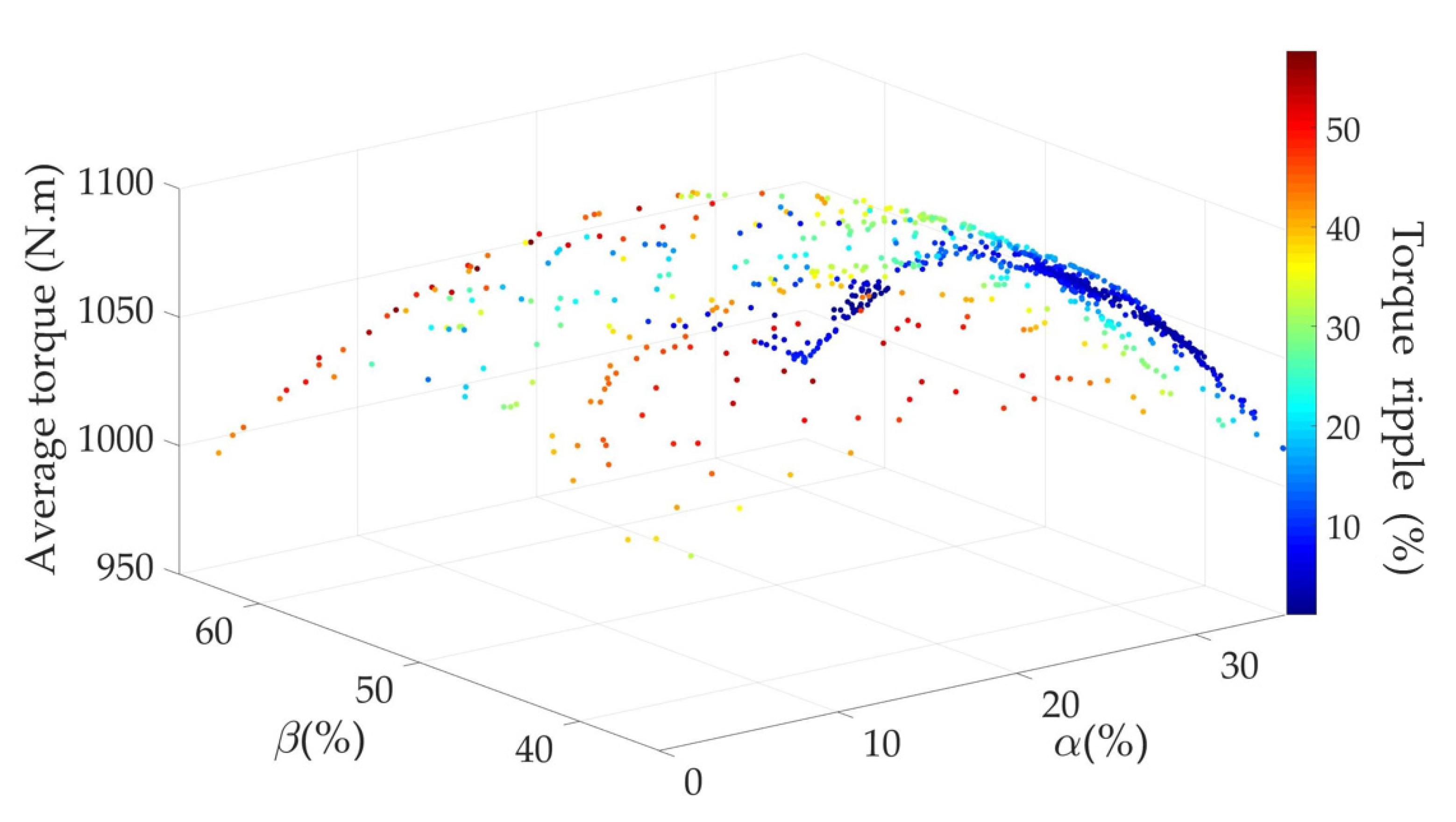
Figure 21 shows the surface response of the objective function, i.e., the average torque (N.m), with respect to the two quantities α (%) and β (%). The color code in the figure represents the torque ripple percentage (%). The red dots indicate the individuals with the highest torque ripples, while the dark blue indicates the most affordable individuals or the individuals with the lowest torque ripple. It is noticeable that there is saturation of the blue dots over a part of the parameter range. This means that the algorithm is looking for the optimal points in this interval that give the maximal value of the average torque while respecting the constraint related to the torque ripples.
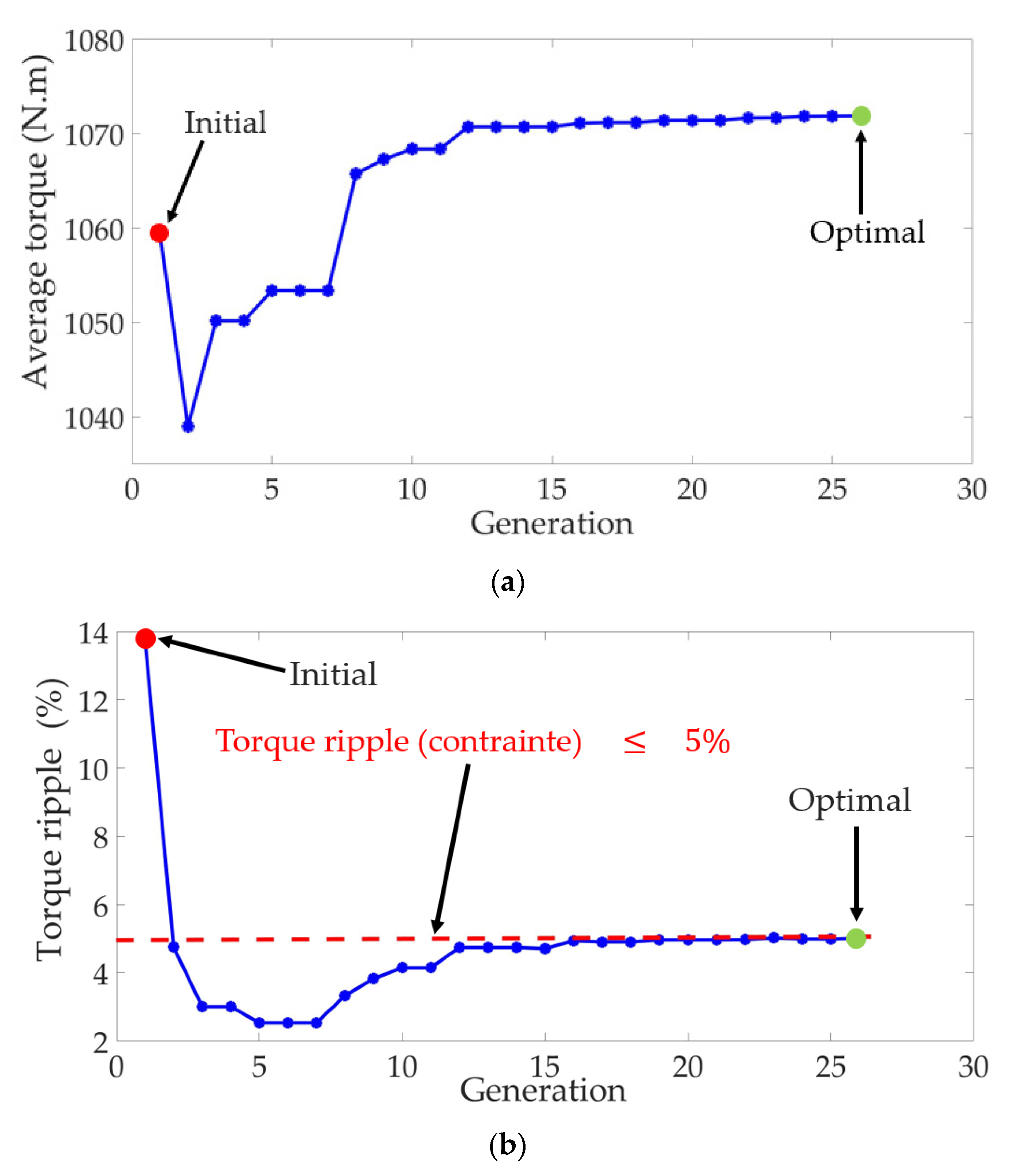
Figure 22 depicts the optimization history, i.e., the evolution of the average torque over generations (Figure 22a) and the evolution of the torque ripple over generations (Figure 22b).
The initial model is infeasible due to the high torque ripple ratio, but from the second prototype, the torque ripple ratio is below 5%. However, the objective function is lower than the initial one, although the search is mainly random. The objective function strictly increases from the 1st generations up to the 12th generation while maintaining the constraint. Beyond this generation, it progresses weakly since the torque ripple approaches the limit of the constraint. Lastly, the objective function remains almost constant from the 24th generation until it reaches the optimum.
Figure 23a,b shows the evolutions of the ratio of the tangential part of the magnets α and the stator slot opening ratio β. It can be noticed that from the 10th generation, their variations are not important enough, meaning that the algorithm is close to finding the optimal value.
The optimal values of the objective function, along with those of the quantities to vary, are summarized in Table 6 and are compared with the initial machine design. Although both machines offer almost the same average torque output, the torque ripple is considerably reduced and the power factor remains almost constant.
The obtained results are within the range of what can be found in the few other works in terms of ripple ratio reduction in close structures. Table 7 shows the two machines with the lowest-rated torques.
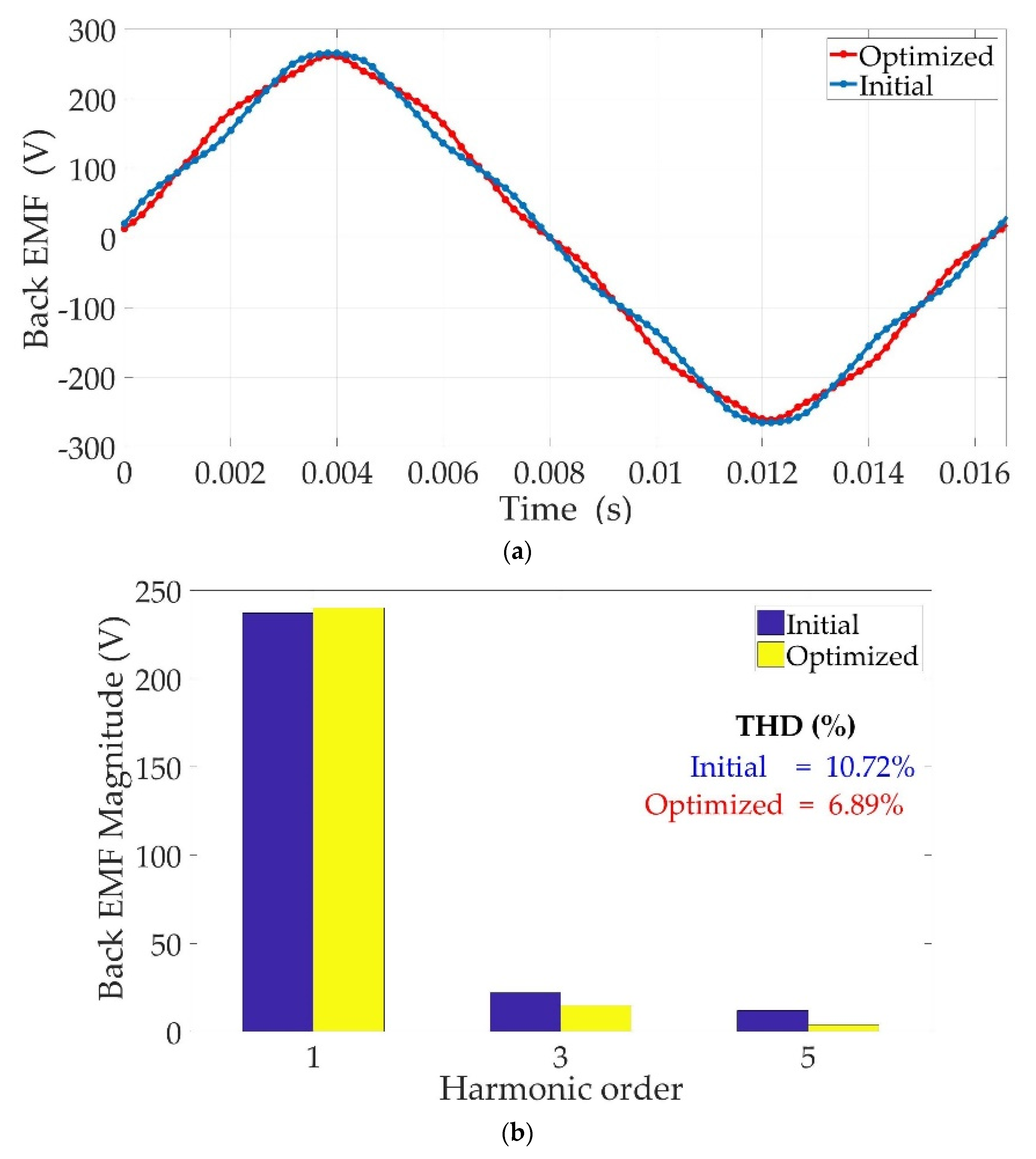
Figure 24a shows a comparison between the phase back-EMF vs. the time of the initial and optimized prototypes, while Figure 24b compares the amplitudes of the first harmonics of both machines. The no-load back-EMFs of both topologies have an almost sinusoidal distribution. The first harmonic of the optimized machine is slightly higher than that of the initial one, while the third and fifth harmonics are reduced.
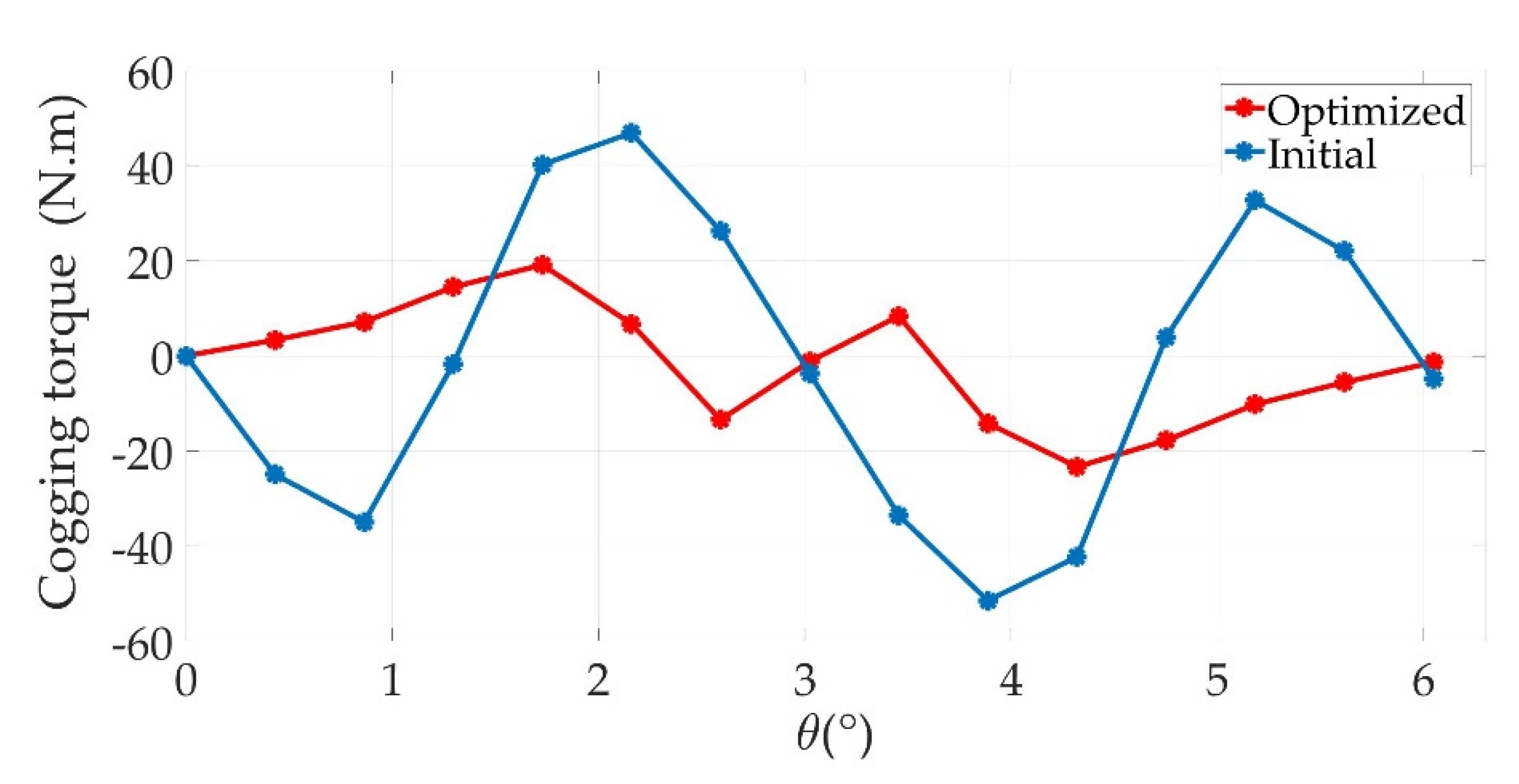
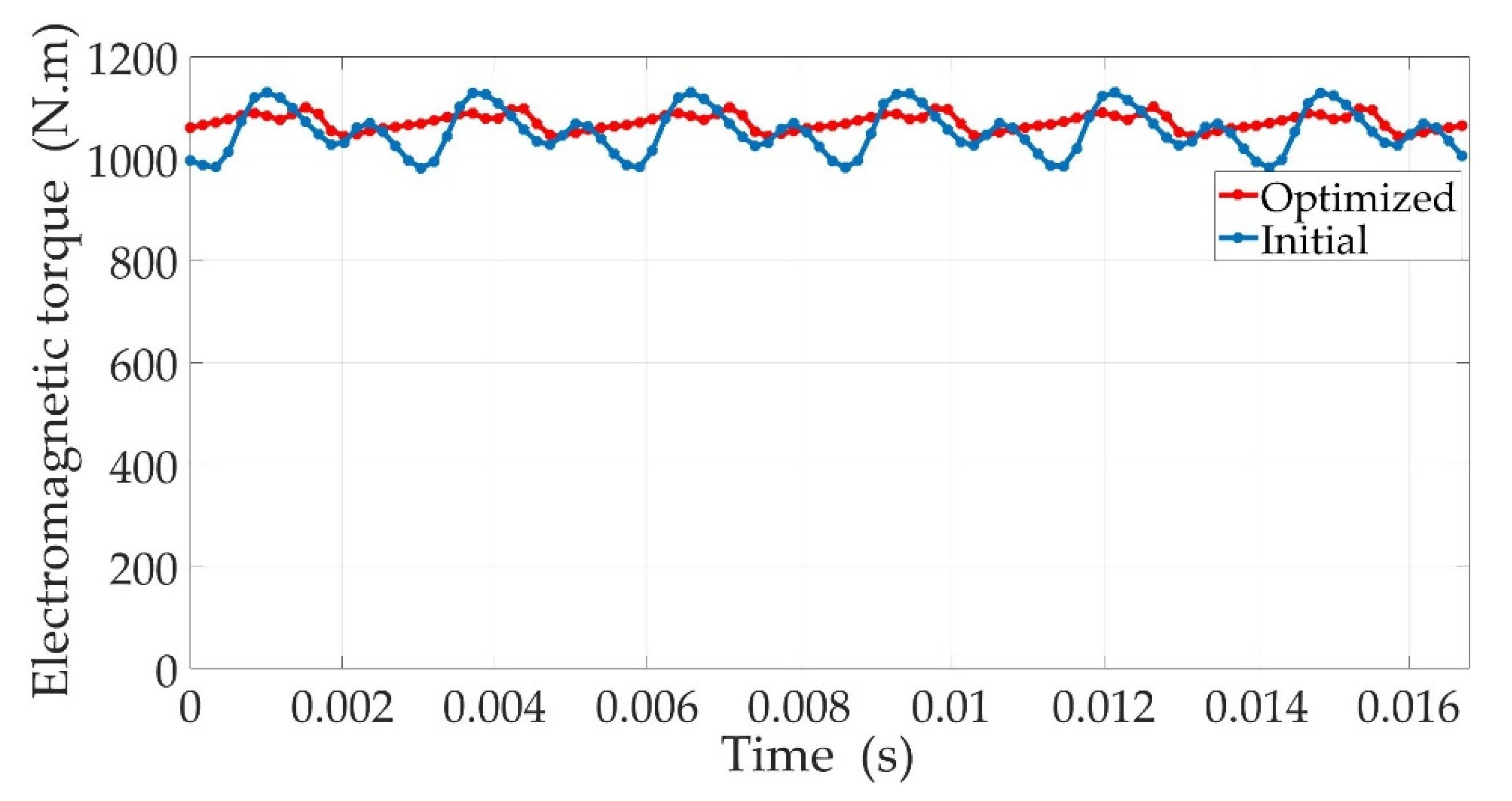
The cogging torque with respect to the rotor position and rated torque vs. time are shown in Figure 25 and Figure 26, respectively. It can be seen that the initial PMVM peak-to-peak cogging torque is equal to 98 N.m, while the value of the optimized one is 42 N.m, and thus, reduced by 57%. When operating under rated motor mode conditions, the torque ripple decreases significantly from 14.08% to 5% between the optimized and initial prototypes. At the same time, the average torque increases from 1055 Nm to 1072 N.m for the optimal machine. The optimized prototype thus meets the requirement of the application with a torque ripple ratio below 5% and a power factor of interesting value.

9. Conclusions

This paper presents the design of a PMVM internal rotor to be used as a direct-drive machine for an urban EV application. A first prototype has been designed and sized from the specification of the application. A study of its performance using FEA shows that the machine almost meets the specification but the torque ripple ratio is too high for the prototype to constitute a good solution. A quasi-Halbach configuration of the magnets is then adopted. First, sensitivity analysis is conducted on the effects of both the stator opening ratio and the ratio of the tangential part of the rotor magnets on quantities such as average torque, its ripple ratio and the power factor and the harmonic content of the back-EMF. This study shows that each of the variables has an effect on these quantities, but not necessarily in the same way. An optimization process is then conducted by varying both variables to increase the average torque while limiting its torque ripple ratio below 5%. An optimized prototype is then reached that meets all the requirements of the application. It should therefore be an efficient candidate to achieve direct-drive operation of an urban vehicle. Future work will deal with the construction of a reduced-power prototype to be tested. Such a machine will be used to validate the simulation results obtained by the virtual prototype in terms of the optimal values of the magnet and the stator teeth opening, but also to demonstrate the relevance of the quasi-Halbach PMVM used as an urban vehicle traction engine.

Author Contributions

W.G. contributed to the conceptualization, methodology, formal analysis, investigation and writing—original draft preparation. A.T. contributed to the conceptualization, methodology, formal analysis, investigation and writing—original draft preparation. T.R. contributed to the conceptualization, formal analysis and writing—original draft preparation. All authors have read and agreed to the published version of the manuscript.

Funding

The work presented in this paper was carried out as part of the PHC Tassili ‘MICSE’ project 19MDU220.

Data Availability Statement

Not applicable.

Conflicts of Interest

The authors declare no conflict of interest.

Appendix A

For the sake of clarity, the expression of the magnetic energy is given below while considering only the first harmonics of the mmfs and the air gap permeance:
                                                                W em = 1 2 0 2 π { ( ε amax cos ( ω t   -   p s θ s ) + ε PMmax cos (   p r ( θ s θ ) ) ) 2 ( P 0 + P 1 s cos ( N s θ s ) } d θ s
Its development is then expressed as:
W em = 1 2 0 2 π { 1 2 ε amax 2 P 0 + 1 2 ε PMmax 2 P 0 + 1 2 ε amax 2 P 0 cos ( 2 ω t   -   2 p s θ s )   + 1 2 ε PMmax 2 P 0 cos ( 2 p r ( θ s - θ ) )       + ε PMmax ε amax P 0 cos ( ω t   -   ( p s + p r ) θ s + p r θ )   + ε PMmax ε amax P 0 cos ( ω t   -   ( p s   -   p r ) θ s -   p r θ ) + 1 2 ε amax 2 P 1 s cos ( N s θ s )   + 1 2 ε PMmax 2 P 1 s cos ( N s θ s )   + 1 4 ε amax 2 P 1 s   [ cos ( 2 ω t   -   ( 2 p s   -   N s ) θ s ) ] + 1 4 ε amax 2 P 1 s [ cos ( 2 ω t   -   ( 2 p s + N s ) θ s ) ]   + 1 4 ε PMmax 2 P 1 s [ cos (   -   ( 2 p r -   N s ) θ s + 2 p r θ ) ] + 1 4 ε PMmax 2 P 1 s [ cos (   -   ( 2 p r + N s ) θ s + 2 p r θ ) ]   + 1 2 ε PMmax ε amax P 1 s [ cos ( ω t -   ( p s + p r -   N s ) θ s + p r θ ) ] + 1 2 ε PMmax ε amax P 1 s [ cos ( ω t   -   ( p s + p r + N s ) θ s + p r θ ) ]   + 1 2 ε PMmax ε amax P 1 s [ cos ( ω t   -   ( p s -   p r -   N s ) θ s -   p r θ ) ] + 1 2 ε PMmax ε amax P 1 s [ cos ( ω t   -   ( p s -   p r + N s ) θ s -   p r θ ) ] } d θ s

References

  1. Chan, C.C. The state of the art of electric, hybrid, and fuel cell vehicles. Proc. IEEE 2002, 90, 247–275. [Google Scholar] [CrossRef] [Green Version]
  2. El Hadraoui, H.; Zegrari, M.; Chebak, A.; Laayati, O.; Guennouni, N. A Multi-Criteria Analysis and Trends of Electric Motors for Electric Vehicles. World Electr. Veh. J. 2022, 13, 65. [Google Scholar] [CrossRef]
  3. Un-Noor, F.; Padmanaban, S.; Mihet-Popa, L.; Mollah, M.N.; Hossain, E. A Comprehensive Study of Key Electric Vehicle (EV) Components, Technologies, Challenges, Impacts, and Future Direction of Development. Energies 2017, 10, 1217. [Google Scholar] [CrossRef] [Green Version]
  4. Al Sakka, M.; Geury, T.; El Baghdadi, M.; Dhaens, M.; Al Sakka, M.; Hegazy, O. Review of Fault Tolerant Multi-Motor Drive Topologies for Automotive Applications. Energies 2022, 15, 5529. [Google Scholar] [CrossRef]
  5. Cai, W.; Wu, X.; Zhou, M.; Liang, Y.; Wang, Y. Review and Development of Electric Motor Systems and Electric Powertrains for New Energy Vehicles. Automot. Innov. 2021, 4, 3–22. [Google Scholar] [CrossRef]
  6. Chau, K.T. Electric Vehicle Machines and Drives: Design, Analysis and Application; John Wiley & Sons: Solaris South Tower, Singapore, 2015. [Google Scholar]
  7. Chasiotis, I.D.; Karnavas, Y.L. Designing High Power Density In-Wheel PMSM for Sustainable Hybrid Electric Vehicles. In Proceedings of the 2019 IEEE Workshop on Electrical Machines Design, Control and Diagnosis (WEMDCD), Athens, Greece, 22–23 April 2019. [Google Scholar]
  8. Iyer, L.V.; Minaker, B.; Mukherjee, K.; Tjong, J.; Kar, N.C. On-board direct-drive surface permanent magnet synchronous machine with fractional-slot concentrated windings for electric vehicles. In Proceedings of the 2016 IEEE Canadian Conference on Electrical and Computer Engineering (CCECE), Vancouver, BC, Canada, 15–18 May 2016. [Google Scholar] [CrossRef]
  9. Xu, S.; Wei, L.; Zhang, X.; Bai, Z.; Jiao, Y. Research on Multi-Mode Drive Optimization Control Strategy of Four-Wheel-Drive Electric Vehicles with Multiple Motors. Sustainability 2022, 14, 7378. [Google Scholar] [CrossRef]
  10. Gong, J.; Zhao, B.; Huang, Y.; Semail, E.; Nguyen, N.K. Quantitative Comparisons of Outer-Rotor Permanent Magnet Machines of Different Structures/Phases for In-Wheel Electrical Vehicle Application. Energies 2022, 15, 6688. [Google Scholar] [CrossRef]
  11. Watts, A.; Vallance, A.; Whitehead, A.; Hilton, C.; Fraser, A. The Technology and Economics of In-Wheel Motor. SAE Intern. J. Passeng. Cars-Electron. Electr. Syst. 2010, 3, 37. [Google Scholar]
  12. Jung, Y.-H.; Park, M.-R.; Kim, K.-O.; Chin, J.-W.; Hong, J.-P.; Lim, M.-S. Design of High-Speed Multilayer IPMSM Using Ferrite PM for EV Traction Considering Mechanical and Electrical Characteristics. IEEE Trans. Ind. Appl. 2020, 57, 327–339. [Google Scholar] [CrossRef]
  13. Fan, X.; Zhang, B.; Qu, R.; Li, D.; Li, J.; Huo, Y. Comparative Thermal Analysis of IPMSMs With Integral-Slot Distributed-Winding (ISDW) and Fractional-Slot Concentrated-Winding (FSCW) for Electric Vehicle Application. IEEE Trans. Ind. Appl. 2019, 55, 3577–3588. [Google Scholar] [CrossRef]
  14. Aiso, K.; Kan, A. Performance Comparison of High-Speed Motors for Electric Vehicle. World Electr. Veh. J. 2022, 13, 57. [Google Scholar] [CrossRef]
  15. Jahns, T.M. The expanding role of PM machines in direct-drive applications. In Proceedings of the 2011 International Conference on Electrical Machines and Systems, Beijing, China, 20–23 August 2011. [Google Scholar] [CrossRef]
  16. Kabasawa, A.; Takahashi, K. Development of the IMA Motor for the V6 Hybrid Midsize Sedan. In Proceedings of the SAE World Congress, Detroit, MI, USA, 11–14 April 2005. [Google Scholar]
  17. Toba, A.; Lipo, T.A. Novel dual-excitation permanent magnet vernier machine. In Proceedings of the Conference Record of the 1999 IEEE Industry Applications Conference. Thirty-Forth IAS Annual Meeting, Phoenix, AZ, USA, 3–7 October 1999. [Google Scholar]
  18. Liu, C.; Zhong, J.; Chau, K.T. A Novel Flux-Controllable Vernier Permanent-Magnet Machine. IEEE Trans. Magn. 2011, 47, 4238–4241. [Google Scholar] [CrossRef] [Green Version]
  19. Qu, R.; Li, D.; Wang, J. Relationship between magnetic gears and vernier machines. In Proceedings of the 2011 International Conference on Electrical Machines and Systems, Beijing, China, 20–23 August 2011. [Google Scholar]
  20. Zhang, J.; Tounzi, A.; Delarue, P.; Piriou, F.; Leontidis, V.; Dazin, A.; Caignaert, G.; Libaux, A. Quantitative Design of a High Performance Permanent Magnet Vernier Generator. IEEE Trans. Magn. 2017, 53, 1–4. [Google Scholar] [CrossRef] [Green Version]
  21. Kim, B.; Lipo, T.A. Operation and Design Principles of a PM Vernier Motor. IEEE Trans. Ind. Appl. 2014, 50, 3656–3663. [Google Scholar] [CrossRef]
  22. Moldovan, D.V.; Jurca, F.N.; Marţiş, C.S.; Minciunescu, P.; Vărăticeanu, B. The Influence of Permanent Magnets’ Position in the Double Stator Vernier Machine’s Performances. In Proceedings of the 2019 Electric Vehicles International Conference (EV), Bucharest, Romania, 3–4 October 2019. [Google Scholar]
  23. Liu, C.; Chau, K.T.; Zhang, Z. Novel Design of Double-Stator Single-Rotor Magnetic-Geared Machines. IEEE Trans. Magn. 2012, 48, 4180–4183. [Google Scholar] [CrossRef] [Green Version]
  24. Guendouz, W.; Tounzi, A.; Rekioua, T. Analysis of PM Vernier machine prototypes aimed at a direct drive operating of EV. In Proceedings of the IECON 2022–48th Annual Conference of the IEEE Industrial Electronics Society, Brussels, Belgium, 17–20 October 2022. [Google Scholar]
  25. Jia, L.; Lin, M.; Le, W.; Li, N.; Kong, Y. Dual-Skew Magnet for Cogging Torque Minimization of Axial Flux PMSM With Segmented Stator. IEEE Trans. Magn. 2020, 56, 1–6. [Google Scholar] [CrossRef]
  26. Cao, L.; Zuo, Y.; Xie, S.; Hoang, C.C.; Han, B.S.; Lee, C.H.T. A Comparison of Permanent-Magnet Vernier Motor and Interior Permanent-Magnet Motor for Hybrid Electric Vehicles. In Proceedings of the 2022 International Power Electronics Conference (IPEC-Himeji 2022-ECCE Asia), Himeji, Japan, 15–19 May 2022. [Google Scholar]
  27. Wu, D.; Xiang, Z.; Zhu, X.; Quan, L.; Jiang, M.; Liu, Y. Optimization Design of Power Factor for an In-Wheel Vernier PM Machine From the Perspective of Air-Gap Harmonic Modulation. IEEE Trans. Ind. Electron. 2020, 68, 9265–9276. [Google Scholar] [CrossRef]
  28. Adnani, K.; Shafiei, S.; Millimonfared, J.; Moghani, J.S. Modified Unipolar Hybrid Permanent Magnet Vernier Machine Using Halbach Array Configuration. In Proceedings of the 2019 10th International Power Electronics, Drive Systems and Technologies Conference (PEDSTC), Shiraz, Iran, 12–14 February 2019. [Google Scholar]
  29. Altair Engineering Flux 2D & HyperStudy 2022 Software Documentation. Available online: http://fluxmotordoc.altair.com/webroot/uploads/helponline/Documentation/2022/Installation%20guide/Installation_guide_en.pdf (accessed on 1 November 2022).
  30. Li, Q.; Fan, T. Torque Improvement of External-Rotor Permanent Magnet Machine Using Flux Concentrated Rotor. In Proceedings of the 2018 IEEE International Magnetics Conference (INTERMAG), Singapore, 23–27 April 2018. [Google Scholar]
  31. Liu, Y.; Li, H.Y.; Zhu, Z.Q. A High-Power Factor Vernier Machine With Coil Pitch of Two Slot Pitches. IEEE Trans. Magn. 2018, 54, 1–5. [Google Scholar] [CrossRef]
  32. Huang, J.; Fu, W.; Niu, S.; Zhao, X. Comparative Analysis of Different Permanent Magnet Arrangements in a Novel Flux Modulated Electric Machine. IEEE Access 2021, 9, 14437–14445. [Google Scholar] [CrossRef]
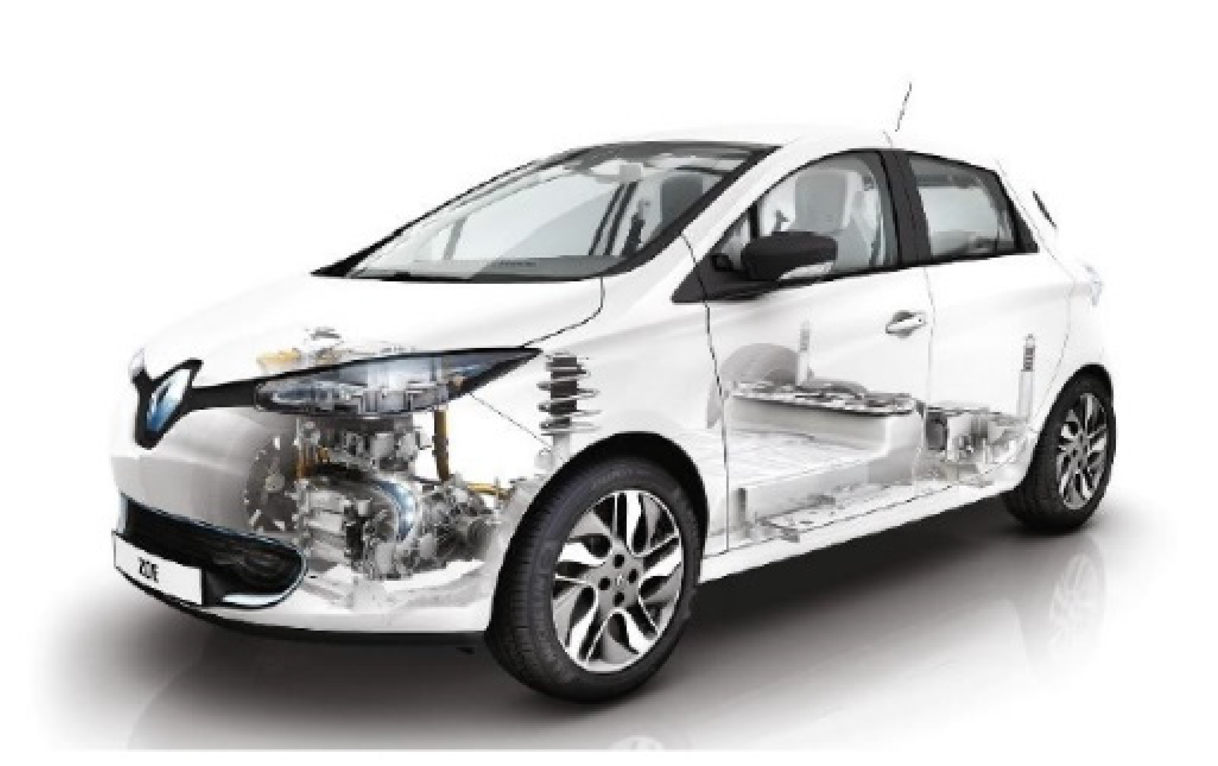
Figure 1. Electric vehicle Renault ZOE.
Machines 11 00136 g001
Figure 2. The power train of Renault ZOE: electrical part (a) and mechanical part (b).
Machines 11 00136 g002
Figure 3. Cross-section of the designed prototype.
Machines 11 00136 g003
Figure 4. Definition of the main geometric parameters of PMVM structure.
Machines 11 00136 g004
Figure 5. Stator (a) and rotor (b) of the designed prototype.
Machines 11 00136 g005
Figure 6. Mesh of a 1/2 model of the PMVM.
Machines 11 00136 g006
Figure 7. No-load magnetic field density in the cross-section of the initial prototype (a) and electromagnetic torque vs. time (b).
Machines 11 00136 g007
Figure 8. Definition of the two variables studied: (a) the ratio λ s s / λ s ; (b) the ratio λ H / λ r .
Machines 11 00136 g008
Figure 9. (a) Back-EMF vs. time for different ratios β (α = 0%). (b) Magnitude of the first 3 harmonics of the back-EMF for different ratios β (α = 0%).
Machines 11 00136 g009
Figure 10. Cogging torque vs. rotor position for different ratios β (α= 0%).
Machines 11 00136 g010
Figure 11. Cogging torque peak-to-peak magnitude for different ratios β (α = 0%).
Machines 11 00136 g011
Figure 12. (a) Back-EMF curve at different ratios α (β = 50%). (b) Back-EMF magnitude of harmonic order at different ratios α (β = 50%).
Machines 11 00136 g012
Figure 13. Cogging torque vs. rotor position for different ratios α (β = 50%).
Machines 11 00136 g013
Figure 14. Cogging torque peak-to-peak magnitude for different ratios α (β = 50%).
Machines 11 00136 g014
Figure 15. Average torque and torque ripple for different ratios β (α = 0%).
Machines 11 00136 g015
Figure 16. Power factor with different ratios β (α = 0%).
Machines 11 00136 g016
Figure 17. Average torque and torque ripple for different ratios α (β = 50%).
Machines 11 00136 g017
Figure 18. Power factor with different ratios α (β = 50%).
Machines 11 00136 g018
Figure 19. Optimization process with coupling between HyperStudy and Flux.
Machines 11 00136 g019
Figure 20. Flowchart for genetic algorithm.
Machines 11 00136 g020
Figure 21. MOGA-based optimization results of the one optimization objective and one constraint.
Machines 11 00136 g021
Figure 22. Optimization history. (a) Evolution of the average torque over generations. (b) Evolution of the torque ripple over generations.
Machines 11 00136 g022
Figure 23. Optimization history. (a) Evolution of α over generations. (b) Evolution of β over generations.
Machines 11 00136 g023
Figure 24. Comparison of back-EMFs. (a) Back-EMF vs. time. (b) First harmonic magnitudes.
Machines 11 00136 g024
Figure 25. Comparison of cogging torque of two machines.
Machines 11 00136 g025
Figure 26. Comparison of electromagnetic torque of two machines.
Machines 11 00136 g026
Table 1. Vehicle specifications.
SymbolParameters
(Unit)
Value
A n Autonomy NEDC
(km)
370
C b a t t e r y Battery Capacity
(kw/h)
42
V d c Battery voltage
(V)
430
L/W/HLength/width/height
(mm)
4084/1730/1562
M v e h i c l e Vehicle mass
(kg)
1480
p l o a d Payload
(kg)
486
r w h e e l Wheel radius
(m)
0.2
η g Gear transmission efficiency
(%)
90
i g Gear box ratio 9.3
V m a x Top speed
(km/h)
135
t a c c Acceleration time (0–100 km/h)
(s)
13.2
Table 2. Characteristics of the Q90 motor.
SymbolParameters
(Unit)
Value
FWDForward locomotion/
P m a x Peak power
(kW)
65
P rated Rated power
(kW)
40
T m a x Peak torque
(N.m)
220
m a x Maximum speed
(rpm)
11,300
b a s e Base speed
(rpm)
3000
η M Efficiency
(%)
95
Table 3. Design targets for the direct-drive motor to propel an EV ZOE.
SymbolParameters
(Unit)
Value
P m a x Peak power
(kW)
58.5
P rated Rated power
(kW)
36
T m a x Peak torque
(N.m)
1840
T r a t e d Rated torque
(N.m)
1060
m a x Maximum speed
(rpm)
1215
b a s e Base speed
(rpm)
322
Table 4. Main geometric parameters of the prototype drive.
SymbolParameters
(Unit)
Value
mPhase number
-
3
n s   Number of turns per slot
-
18
DOuter rotor diameter
(mm)
240
P c s Thickness of stator yoke
(mm)
20
P c r Thickness of rotor yoke
(mm)
20
LActive length
(mm)
350
h m Thickness of PM
(mm)
6.5
eThickness of air gap
(mm)
1
I r a t e d Rated current
(A)
80
Table 5. The limits of variation the two parameters.
FormulaSymbolTerminals LowTerminals High
λ s s / λ s β35%65%
λ H / λ r α0%35%
Table 6. The comparison of the quantity values of the optimized and initial prototypes.
Variable/ObjectiveInitialOptimal
α0%29.57%
β50%43.46%
T A v e r a g e 1055 N.m1073 N.m
T R i p p l e 14.08%5%
P f 0.840.84
Table 7. A comparison of the quantity values with recent works.
Optimization TechniqueType MachineInitialOptimized
T A v e r a g e T R i p p l e T A v e r a g e T R i p p l e
Based on sensitivity analysisSP-PMVM [32]62.1 N.m10.1%65.5 N.m3.3%
Based on sensitivity analysisPMHVM [28]29.21 N.m3.21%29.72 N.m2.95%
Disclaimer/Publisher’s Note: The statements, opinions and data contained in all publications are solely those of the individual author(s) and contributor(s) and not of MDPI and/or the editor(s). MDPI and/or the editor(s) disclaim responsibility for any injury to people or property resulting from any ideas, methods, instructions or products referred to in the content.