Article

A Novel Tooth Modification Methodology for Improving the Load-Bearing Capacity of Non-Orthogonal Helical Face Gears

School of Mechanical Engineering and Automation, Fuzhou University, Fuzhou 350108, China
*
Author to whom correspondence should be addressed.
Machines 2023, 11(12), 1077; https://doi.org/10.3390/machines11121077
Submission received: 16 November 2023 / Revised: 5 December 2023 / Accepted: 6 December 2023 / Published: 8 December 2023
(This article belongs to the Section Machine Design and Theory)

Abstract

:
This study proposes a double-crown tooth surface modification technology that improves the load-carrying capacity of non-orthogonal helical tooth surface gears. The tooth modification is determined by a modified rack-cutter, and its feed motion is related to an intentionally designed transmission error. The novelty of the tooth modification design is that the transmission error can be pre-designed. First, changing the tooth profile of the tool enables preliminary modification along the tooth profile direction; second, by modifying the interaction between the tool and the machined gear, subsequent fine adjustments are made to the contact path. This two-stage tooth modification strategy not only retains the advantages of the traditional method but also significantly improves the balance of the load distribution on the tooth surface through an original contact path modification strategy. Through systematic tooth contact analysis (TCA) and loaded tooth contact analysis (LTCA), it was verified that the new method reduces contact stress and tooth root bending stress and improves the gear’s resistance to misalignment errors. This research provides the basis and motivation for further exploring and improving this tooth profile modification technology to solve the challenges faced by more complex gear systems.

1. Introduction

Transmission systems, which are integral to mechanical devices, benefit significantly from the enhancement of gear performance, as it directly affects the overall quality of the equipment. The modification of gear teeth is a prevalent method for enhancing the performance of gear transmission [1,2,3,4,5,6]. By implementing this technology, the typical line contact found on unmodified gear teeth transitions to point contact after modification. This shift notably diminishes the susceptibility to errors, resulting in a concurrent reduction in both vibration and noise while enhancing the meshing of gears [7]. The process of tooth modification stands out for both its effectiveness and cost-efficiency. It involves precise, micron-level alterations to the gear teeth, leaving the macro structure and overall dimensions of the gear system intact; importantly, it also does not contribute additional weight to the system. Its broad application across diverse gear-driven mechanisms underscores its utility [8,9,10,11,12].
As an evolved transmission variant, face gear systems are pivotal in the realm of machinery, notably within helicopter main reducers, where they have been utilized with considerable success. These systems, due to their rapid operational speeds and substantial load requirements, necessitate tooth modifications [13,14,15,16,17]. The chief aim of teeth modification in this context is to redistribute the forces acting across the teeth surfaces and stabilize the contact patterns in the central tooth zone. Techniques for gear tooth adjustments may include profile, longitudinal, and three-dimensional modifications, collectively referenced here as conventional tooth modification methods. Although these adjustments can lead to diminished vibration and noise, they can inadvertently cause the load to concentrate in the central region of the teeth, thereby posing a risk for stress concentration. This is particularly concerning in the current landscape where machine loads are progressively increasing, leading to immediate loading of the middle tooth region subsequent to the engagement of the top and root areas. The resulting spike in contact stress can not only accelerate surface wear and reduce the operational lifespan but also decrease the efficiency of gear drives [18,19,20,21,22,23,24].
However, there are some limitations in the current tooth surface modification methods, such as the transmission error correction of helical bevel gears and the high-order transmission error (HTE) correction of helical involute gears. These aspects still require further research and improvement. Some researchers have begun to study new methods of tooth surface modification. Su et al. [25] introduced a method to correct transmission errors up to the seventh order in spiral bevel gears. Their research demonstrated that following this correction, the bending stresses on the gear teeth were reduced compared to those observed on parabolic tooth surfaces, with the contact stress remaining largely unaffected. Jiang et al. [26] designed a high-order transmission error correction for helical involute gears through particle swarm optimization (PSO), but there is a lack of correction during the correction process with full consideration of the polynomial coefficients. In addition, Jia et al. [27] proposed a new method based on compensated conjugation to reduce the peak-to-peak transfer error in the design of cylindrical gear tooth surface modification. Yu et al. [28] and Yang et al. [29] proposed an improved tooth surface modification strategy based on spiral theory and the curvature synthesis method. Further research can be carried out on the optimization of transmission performance and surface shape. Mu et al. [30] proposed a functional design-oriented gear design method, emphasizing the importance of gear transmission performance with high-order transmission errors. Samani et al. [31] conducted a nonlinear vibration study on a spiral bevel gear pair with high-order transmission errors and parabolic transmission errors. Korta and Mundo [32] conducted a gear optimization study using the response surface method. Lu et al. [33] developed a tooth profile generation algorithm for non-bevel gears, which is used to correct the pitch points of high-order Archimedes spiral bevel gears and quadratic bevel gears. Finally, Zhao et al. [34] proposed an automatic green onion seedling raising mechanism using an asymmetric transmission high-order non-circular planetary gear train to improve the efficiency of automatic green onion transplanting.
In the above literature, we found that with the continuous improvement of the aviation industry, the new generation of aircraft has put forward higher requirements for face gear transmission systems. Therefore, further research on face gear modification technology still has important practical significance. Traditional modification methods can effectively reduce contact stress, but there is a risk of stress concentration. In order to improve the load-bearing capacity of non-orthogonal helical tooth surface gears, we propose a novel tooth profile modification method, namely the double crown modification method. This method performs corrections along the direction of the tooth profile and the direction of the contact path. By comparing the results of traditional tooth modifications with standard teeth, with and without misalignment errors, the effect of this new tooth modification method is verified.

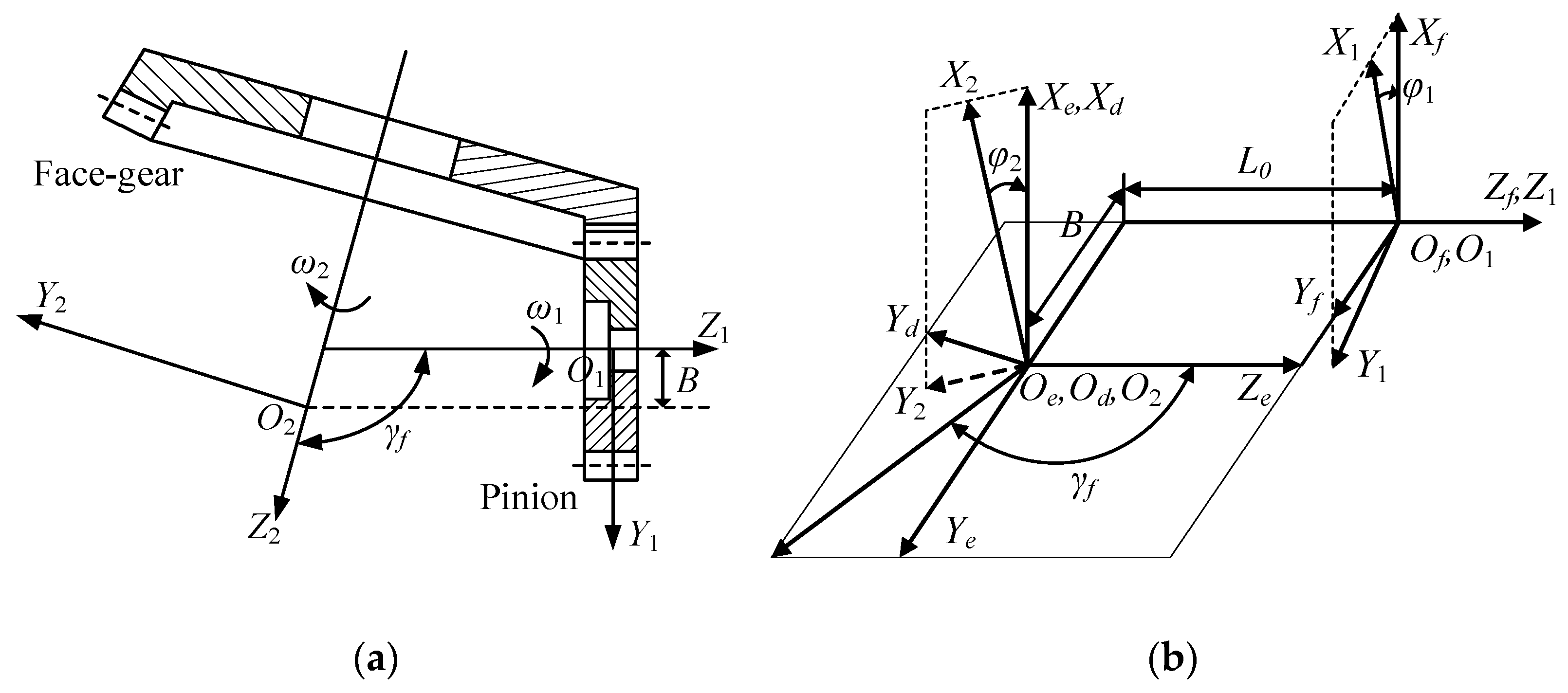
2. Generation of Non-Orthogonal Helical Face Gear Pair

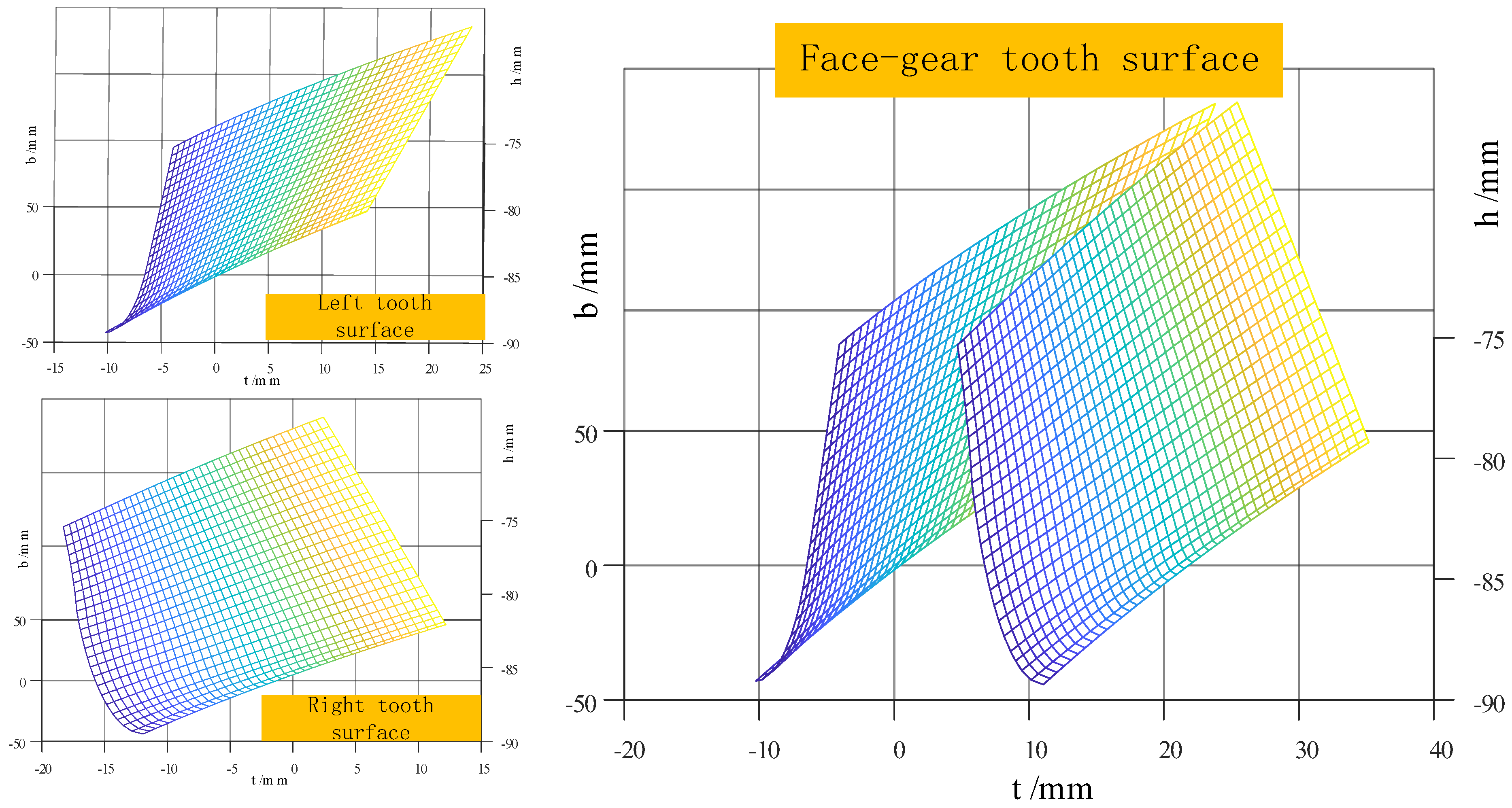
2.1. Generation of Tooth Surface of Face Gear

As shown in Figure 1, the face gear machining process is carried out by using a grinding wheel to simulate a single-tooth gear cutter. The grinding wheel is regarded as a single tooth of the gear cutter, which moves in the direction of the tooth face while rotating and cutting itself, where S2, Sg, and SS are rigidly connected to the face gear, the disk grinding wheel and the virtual cutter, and Z2, Zg, and Zs are the corresponding rotation axes, respectively.
The distance between the origin O2 and Os of the two coordinate systems S2 and SS is L0, and the angle γm is the shaft angle. The center distance between the disk grinding wheel and the virtual cutter is Eg, and Eg is defined as E g = r g r p s , where rps is the radius of the pitch circle of the virtual cutter, and rg is the radius of the pitch circle of the disk grinding wheel; lg is the moving distance of the center of the disk grinding wheel. There are three kinds of motion during the grinding process: the disc-shaped grinding wheel swings around the rotation axis ZS of the virtual gear shaping cutter at an angular velocity ωs, the face gear rotates around its own rotation axis Z2 at an angular velocity ω2, and the grinding wheel rotates around its own rotation axis Xg at a high speed ωg to form a cutting motion.
Through the movement of the tool and the face gear, the position vector of the virtual tool is converted from the coordinate system SS to the coordinate system S2 [35]. Then, the tooth surface of the face gear is generated using the meshing equation.
What is clearly shown in Figure 2 above is a detailed tooth profile illustration of the rack-cutter specifically designed for the purpose of machining the theoretical tooth surfaces of the disk grinding wheel. According to the knowledge of the fundamental principle of gear meshing theory, the tooth surface of the disk grinding wheel depicted in Figure 1 is meticulously shaped through the process of enveloping the toothed surface of the rack-cutter.
The tooth profile of the rack-cutter is determined via Equations (1) and (2).
r a 2 = [ a c 2 u 2 2 ,   u 2 ,   l g , 1 ] T
n a 2 = 1 ( 2 a c 2 u 2 ) 2 + 1 2 2 a c 2 u 2 1 0
In the context of tooth profile modification for the cutter, ac2 represents the modification parameter. The parameters u2 and lg are associated with the flank characteristics of the cutting tool.
The profile of the tooth surface for the hypothetical cutter is defined by Equations (3) and (4).
r s ( u 2 , l g , θ s ) = M s a r a 2 ( u 2 , l g )
n s ( u 2 , θ s ) = L s a n a 2 ( u 2 )
where M s a is a 4 × 4 coordinate transformation matrix from Sa to Ssi, and L s a is a 3 × 3 submatrix of M s a . M s a is determined via Equation (5).
M s a = M s , n s M n s , c M c b M b a
M b a = cos α sin α 0 0.5 s 0 cos 2 α sin α cos α 0 0.5 s 0 sin α cos α 0 0 1 0 0 0 0 1
M c b = cos β 2 0 sin β 2 0 0 1 0 0 sin β 2 0 cos β 2 0 0 0 0 1
M n s , c = 1 0 0 r p s θ s 0 1 0 r p s 0 0 1 0 0 0 0 1
M s , n s = cos θ s sin θ s 0 0 sin θ s cos θ s 0 0 0 0 1 0 0 0 0 1
In Figure 3, the disk grinding wheel rotates around axis Xg at a high speed ωg to form a cutting motion.
The tooth surface of the disk grinding wheel is determined by Equations (10) and (11).
r g ( u 2 , θ g ) = M g s r s ( u 2 )
n g ( u 2 , θ g ) = L g s n s ( u 2 )
where θg is the rotation angle of the face gear; Mgs is a 4 × 4 coordinate transformation matrix from Ss to Sg; and Lgs is a 3 × 3 submatrix of Mgs. Mgs is determined via Equation (12).
M g s = M g t M t s
M t s = 1 0 0 0 0 1 0 E g 0 0 1 0 0 0 0 1
M g t = 1 0 0 0 0 cos θ g sin θ g 0 0 sin θ g cos θ g 0 0 0 0 1
The tooth surface of the face gear is determined by Equation (15).
r 2 ( u 2 , l g , φ g , θ g ) = M 2 g r g ( u 2 , θ g ) f 1 = n g ( u 2 , θ g ) v g 1 ( u 2 , l g , φ g , θ g ) = 0 f 2 = n g ( u 2 , θ g ) v g 2 ( u 2 , l g , φ g , θ g ) = 0
n 2 ( u 2 , l g , φ g , θ g ) = L 2 g n g ( u 2 , θ g )
where M 2 g is a 4 × 4 coordinate transformation matrix from Sg to S2, and L 2 g is a 3 × 3 submatrix of M 2 g . f 1 , f 1 are the meshing equations of face gears in the coordinate system Ss. v g 1 is the grinding wheel’s center speed, while v g 2 is the non-orthogonal helical face gears’ relative speed to the grinding wheel. M 2 g is determined via Equation (17).
M 2 g = M 2 p M p s M s m M m g
M m g = 1 0 0 0 0 1 0 E g 0 0 1 l g 0 0 0 1
M s m = cos φ g sin φ g 0 0 sin φ g cos φ g 0 0 0 0 1 0 0 0 0 1
M p s = 1 0 0 0 0 cos γ m sin γ m L 0 sin γ m 0 sin γ m cos γ m L 0 cos γ m 0 0 0 1
M 2 p = cos θ 2 sin θ 2 0 0 sin θ 2 cos θ 2 0 0 0 0 1 0 0 0 0 1

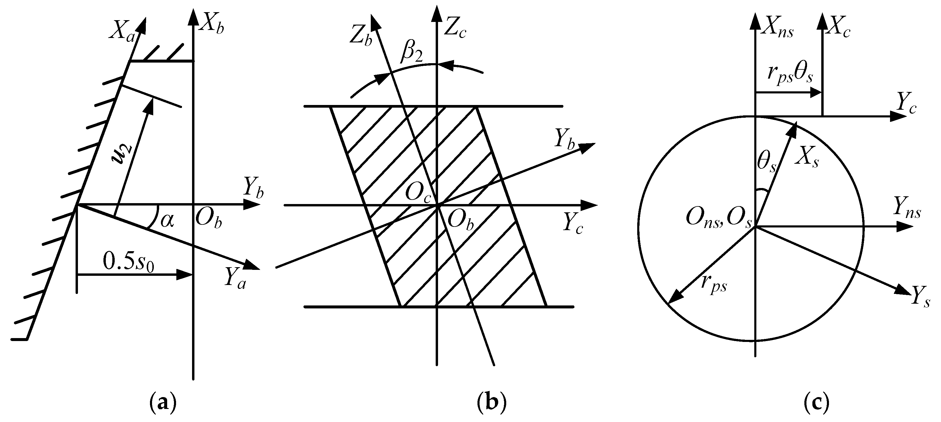
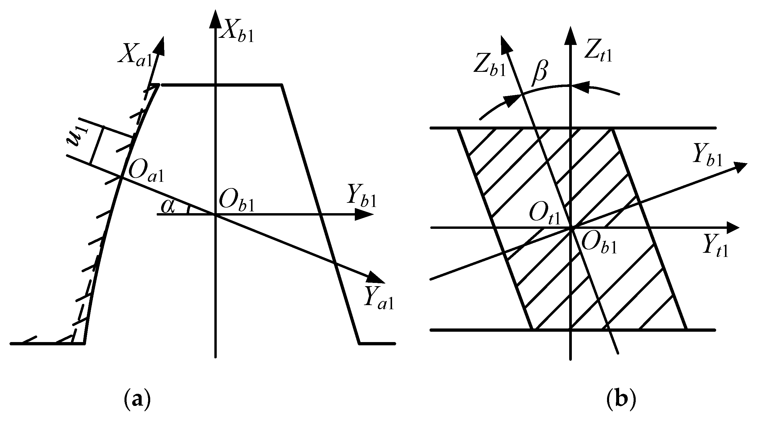
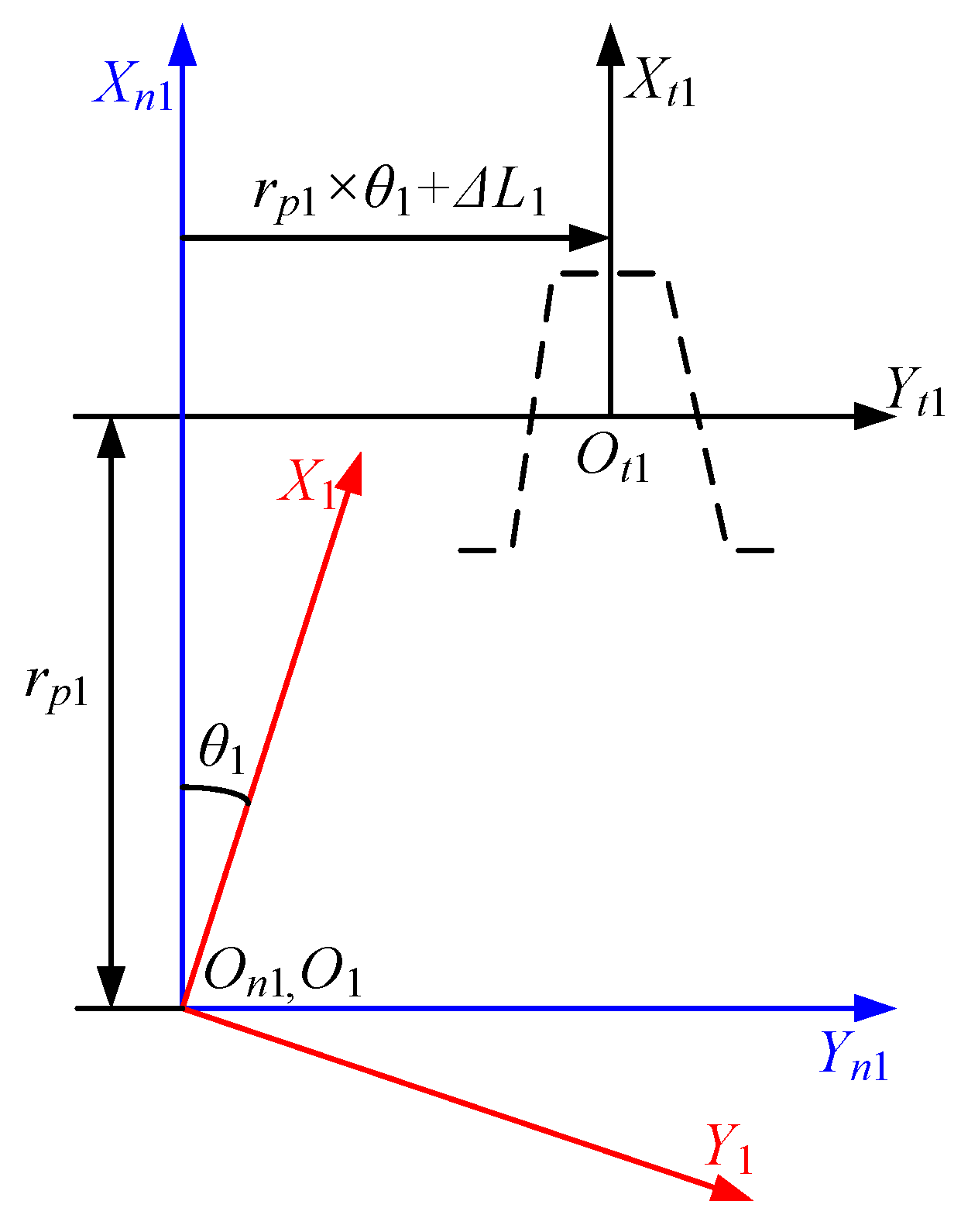
2.2. Generation of Novel Double-Crowned Tooth Surface of Pinion

This research focuses exclusively on the alteration of the pinion tooth. The innovative tooth modification approach is established through the utilization of a modified rack-cutter, alongside its feeding motion, which correlates with a deliberately engineered higher-order transmission error. By meshing with the modified rack, Figure 4 can clearly see the tooth profile of the pinion before and after modification. The amount of practice in the middle is less, and the amount of shaping in and out is larger.
As shown in Figure 5, the coordinate systems Sa1, Sb1, and St1 is connected to the rack-cutter. The tooth modification along the tooth profile direction can be realized based on the tooth modification of the rack-cutter.
In Figure 5, the tooth profile of the rack-cutter is a second-order parabola.
As shown in Figure 6, the pinion is generated by the modified rack-cutter. The motion of the rack-cutter and the produced pinion can be changed to achieve a different direction of tooth modification. The produced pinion’s rotating motion is represented by θ1. ΔL1 is the rack-cutter’s extra translation motion parameter, which is related to the intentional designed high-order transmission error. Sn1 is the fixed coordinate system. rp1 is the pitch radius of the pinion. St1 and S1 are the coordinate systems of the rack-cutter and generated pinion, respectively.
The double-crowned modified pinion surface can be represented by Equation (22).
  r 1 ( u 1 , l 1 , Δ L 1 , θ 1 ) = [ M ] 1 , t 1 r t 1 ( u 1 , l 1 ) n 1 = [ L ] 1 , t 1 n t 1 f ( u 1 , l 1 , Δ L 1 , θ 1 ) = r 1 u 1 × r 1 l 1 r 1 θ 1 = 0
where M 1 , t 1 is a 4 × 4 coordinate transformation matrix from St1 to S1 and L 1 , t 1 is a 3 × 3 submatrix of M 1 , t 1 ; r t 1 and n t 1 are vectors in the coordinate system St1, both obtained via Equation (23).
r t 1 ( u 1 , l 1 ) = [ M ] t 1 , a 1 [ u 1 ,   a 1 u 1 2 ,   l 1 , 1 ] T n t 1 = r t 1 u 1 × r t 1 l 1 / r t 1 u 1 × r t 1 l 1
where a1 is the modification parameter for the tooth profile modification of the cutter; u1 and l1 are the related tooth flank parameters of the cutter.

3. Analysis of Meshing Performance of Face Gears

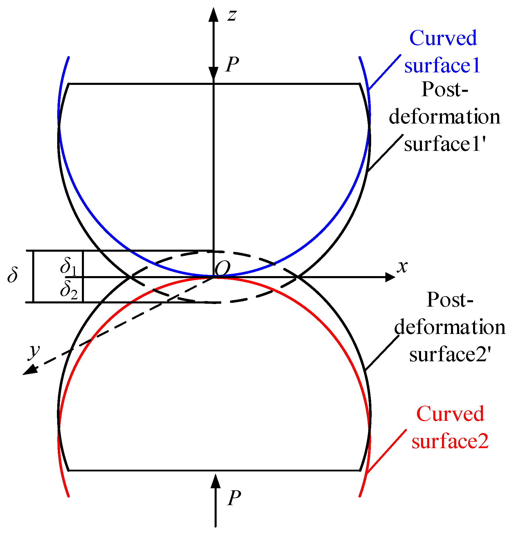
3.1. Tooth Contact Analysis

The tooth touch analysis (TCA) approach was designed to more effectively assess the real state of the tooth flanks while they are touching, and it is a numerical method to program the mesh process of the tooth flanks Σ1 and Σ2 with the use of coordinate transformations in order to obtain the contact imprints and the transmission errors. The structure of the face gear sub-structure is shown in Figure 7, with S1 being the fixed coordinate system of the cylindrical gear and S2 being the fixed coordinate system of the face gear. In the figure, B = rpsrp1 and γf = γm + Δγ, where γm is the shaft angle, and Δγ is the shaft angle error.
The coordinate transformation method is used to describe the equations for the tooth surface of the pinion and face gears in the coordinate system Sf. Equations (24)–(27) can be used to model the tooth surface.
r 2 f u 2 , l g , φ g , θ g , φ 2 = M f 2 r 2 u 2 , l g , φ g , θ g
r 1 f u 1 , l 1 , φ 1 = M f 1 r 1 u 1 , l 1
n 2 f u 2 , l g , φ g , θ g , φ 2 = L f 2 n 2 u 2 , l g , φ g , θ g
n 1 f u 1 , l 1 , φ 1 = L f 1 n 1 u 1 , l 1
where r 1 ( f ) and r 2 ( f ) are position vectors for the pinion’s tooth surface∑1 and face gear ∑2; n 1 ( f ) and n 2 ( f ) are unit normal vectors for the pinion’s tooth surface r 1 ( f ) and the face gear n 2 ( f ) , respectively; M f i (i = 1, 2) is a 4 × 4 matrix; L f i (i = 1, 2) is a 3 × 3 submatrix of M f i (i = 1, 2).
According to the principle of gear meshing, two gears will have a common contact point, which should satisfy that in the same coordinate system, the position vector of this meshing point is the same and the unit normal vector is also the same on both tooth faces. The above conditions can be represented by Equation (28).
f 2 ( u 2 , l g , φ g , θ g ) = 0 r 2 ( f ) u 2 , l g , φ g , θ g , φ 2 = r 1 ( f ) u 1 , l 1 , φ 1 n 2 ( f ) u 2 , l g , φ g , θ g , φ 2 = n 1 ( f ) u 1 , l 1 , φ 1
where φ2 is the rotation angle of the face gear; φ1 is the rotation angle of the pinion.
Considering edge contact, when one of the pinion teeth exits meshing, the contact range is truncated from the original ellipse to a semi-ellipse, which is obviously smaller than the contact area in normal meshing, resulting in stress concentration. Currently, the coordinate system in which the two tooth surfaces are located is Sf, the distance between the tooth contact point and the coordinate origin is the same, and the tangent vector of the pinion’s tooth top at the contact point is perpendicular to the normal vector of the tooth surface of the face gear. When the pinion enters into meshing, there is also a truncation of the contact area, resulting in edge contact. By placing the two tooth surfaces in the same coordinate system Sf, the distance from the tooth contact point to the coordinate origin is the same, and the top edge tangent vector of the face gear is perpendicular to the tooth normal vector of the pinion.
Both cases can be represented by Equations (29) and (30).
r 1 ( f ) ( u 1 , l 1 , φ 1 ) l 1 n 2 ( f ) = 0
r 2 ( f ) ( u 2 , l g , φ g , θ g , φ 2 ) l g n 1 ( f ) = 0
where r 1 ( f ) ( u 1 , l 1 , φ 1 ) l 1 is the tangent vector of the edge of the crest of the pinion; r 2 ( f ) ( u 2 , l g , φ g , θ g , φ 2 ) l g is the tangent vector of the edge of the crest of the face gear; n 1 ( f ) is the normal vector of the tooth surface of pinion; n 2 ( f ) is the normal vector of the tooth surface of the face gear.
By solving the above equations, the contact point of the face gear can be determined.

3.2. Calculation of Hertzian Contact Stress

According to the theory of contact mechanics, the contact location is deformed by the load, and the contact area expands outward into an ellipse with the contact point as the center. Among these, the ellipse’s center experiences the most deformation and contact stress, which gradually diminishes as it moves outward. The curvature of the position of the contact point affects the size of the elliptical contact region, and a corresponding digitizing program can be written to calculate the corresponding curvature.
The two gears in contact are deformed by the normal load and expand into an elliptical contact area at the original contact point O, according to the Hertzian elastic contact theory [36,37]. The contact deformation is shown in Figure 8, where δ1 and δ2 are the shape variables of surface 1 and surface 2, respectively.
B A = a 2 / b 2 E e K e K e E e
F n = 2 3 p 0 π a b
e = 1 b 2 a 2 1 / 2
1 E * = 1 v 1 2 E 1 + 1 v 2 2 E 2
p 0 = 1.5 F n π a b
where Fn is the contact point’s normal load, a is the ellipse’s semi-professional axis; b is its semi-minor axis; e is the eccentricity of the ellipse, and K(e) and E(e) are the elliptic integrals of the first and second kinds, respectively; p0 is the maximum contact stress.

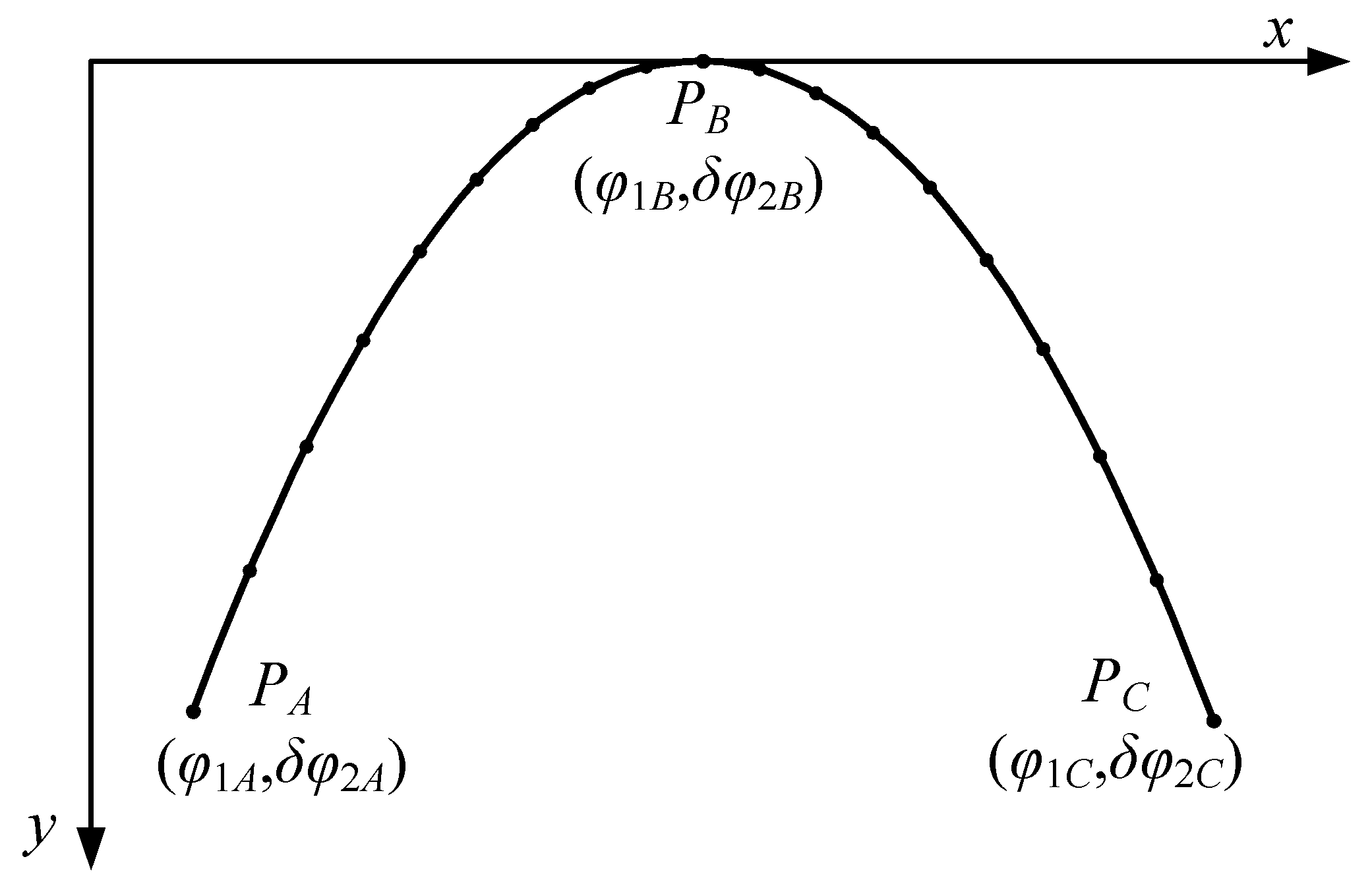
4. Designation of Intentional High-Order Transmission Error

In Figure 9, the transmission error (TE) is pre-designed as a sixth-order parabolic function. The x-coordinate and y-coordinate of the five given points are the rotation angle of the pinion and the transmission error of the face gear, respectively. The points PA and PE denote the positions of the gears entering and exiting meshing, respectively. The points PB and PD are the two peaks of the curve. The point PC is the transition point in the middle, and the positional relationship between PB, PC, and PD is determined by the two parameters of λB and λD. Tm denotes the meshing period of the gears.
The TE function of Figure 8 can be represented as Equation (35).
δ φ 2 = a 0 + a 1 φ 1 + a 2 φ 1 2 + a 3 φ 1 3 + a 4 φ 1 4 + a 5 φ 1 5 + a 6 φ 1 6 = X Y T X = a 0     a 1     a 2     a 3     a 4     a 5     a 6 Y = 1     φ 1     φ 1 2     φ 1 3     φ 1 4     φ 1 5     φ 1 6
where φ1 is the rotation angle of the pinion; δφ2 is the transmission error; a0~a6 are the coefficients of the HTE function.
Based on the coordinates of the five pre-designed points, the restriction equation of Equation (35) can be written as Equation (36).
x = φ 1 A ,       y = δ φ 2 A x = φ 1 B ,       y = δ φ 2 B x = φ 1 B ,       d y / d x = 0 x = φ 1 C ,       y = δ φ 2 C x = φ 1 D ,       y = δ φ 2 D x = φ 1 D ,       d y / d x = 0 x = φ 1 E ,       y = δ φ 2 E
where
φ 1 C = φ 1 A + φ 1 E 2 φ 1 B = φ 1 C λ B T m φ 1 D = φ 1 C + λ D T m T m = 2 π Z 1
Equation (18) can be written in a matrix form via Equation (38).
A X = B
where
A = 1     φ 1 A     φ 1 A 2     φ 1 A 3         φ 1 A 4         φ 1 A 5         φ 1 A 6 1     φ 1 B     φ 1 B 2     φ 1 B 3         φ 1 B 4         φ 1 B 5         φ 1 B 6 0       1         2 φ 1 B       3 φ 1 B 2     4 φ 1 B 3     5 φ 1 B 4     6 φ 1 B 5 1     φ 1 C     φ 1 C 2     φ 1 C 3         φ 1 C 4         φ 1 C 5         φ 1 C 6 1     φ 1 D     φ 1 D 2     φ 1 D 3         φ 1 D 4         φ 1 D 5         φ 1 D 6 0       1         2 φ 1 D       3 φ 1 D 2     4 φ 1 D 3     5 φ 1 D 4     6 φ 1 D 5 1     φ 1 E     φ 1 E 2     φ 1 E 3         φ 1 E 4         φ 1 E 5         φ 1 E 6 B = δ φ 2 A     δ φ 2 B     0     δ φ 2 C     δ φ 2 D     0     δ φ 2 E T
Then, coefficient vector X is calculated via Equation (40).
X = A 1 B
Figure 10 shows the traditional second-order parabolic transmission error. The TE function can be determined by substituting Equation (41) into Equation (40).
A = 1     φ 1 A     φ 1 A 2 1     φ 1 B     φ 1 B 2 1     φ 1 C     φ 1 C 2 B = δ φ 2 A     δ φ 2 B     δ φ 2 C T
where
φ 1 B = φ 1 A + φ 1 C 2

5. Numerical Examples and Discussions

Only the pinion is modified, herein. The design parameters of the examples of face gears are shown in Table 1. In the following, “non-mod” (non-modification) indicates the results of a tooth surface without modification; “tra-mod” (traditional modification) indicates the results of a tooth surface using the traditional tooth modification method; “nov-mod” (novel tooth modification) indicates the results of a tooth surface using the novel modification method. The input torque was 105 Nm, which was applied to the pinion.
Figure 11 and Figure 12 shows the face gear tooth and pinion tooth models. Gear tooth face establishment is divided into left tooth face and right tooth face. The gear tooth profile parameters can be substituted into the tooth face equation to obtain the left tooth face, and the rack displacement direction and tooth profile parameters to obtain the opposite number can be processed to obtain the right tooth face of the gear. The steps for generating the tooth surface are as follows:
(1)
Parameter calculation. According to the tooth height of the gear shaping cutter, the tooth height parameter z2 of the face gear in the coordinate system S2 is derived;
(2)
Calculate the tooth width. Find the minimum inner diameter R1 of the gear undercut and the maximum outer diameter R2 without tooth tip sharpening, and select an appropriate tooth width within the range of R1 and R2 as the known quantity y2;
(3)
Discrete y2 and z2. Through discretization, i discrete values of y2i (y21, y22, y23, …, y2i) and j discrete values of z2j (z21, z22, z23, …, z2j) are obtained; based on the y2i and z2j, which are used as the input values and substituted into the tooth surface equation, we can obtain i × j values of θSij (θSi1, θSi2, θSi3, …, θSij) and i × j values of φSij (φSi1, φSi2, φSi3, …, φSij);
(4)
Visualization of the working tooth surface. Back-substitute the i × j group (θSij, φSij) into the non-orthogonal asymmetric surface gear tooth surface equation to obtain i × j discrete coordinate points (xij, yij, zij) on the corresponding tooth surface, and apply MatLab instructions to generate work surfaces for gears with non-orthogonal faces.
Similar to the generation method of face gear tooth surfaces, cylindrical gears are also divided into left tooth surfaces and right tooth surfaces. Substitute the tooth shape parameters of the cylindrical gear into the equation, and then use the mesh statement of MATLAB software (2018b) to output the cylindrical gear mesh model, as shown in Figure 12.

5.1. Tooth Modification

Changes in the tooth flanks can often be reflected in the amount of tooth flank modification to study the changes in gear tooth flanks, first analyze the changes in the amount of tooth flank modification.
Figure 13 shows the modification amount of the cylindrical gear tooth surface under different modification methods. As shown in Figure 13a, the cylindrical gear using second-order modification has a medium convex shape, with a small amount of modification in the middle position, and a large amount of modification near the meshing in and meshing out positions. The overall modification amount transitions smoothly, but the uneven distribution of the modification amount on the tooth surface may have adverse effects. In Figure 13b, the cylindrical gear is modified according to the preset HTE. Different from the traditional convex TE, the HTE is concave, and the corresponding tooth surface modification amount is also concave. It can be clearly seen from the modification amount that the high-order modification design ensures a higher modification amount in the middle area, which can make the distribution of the modification amount on the tooth surface more reasonable. At the same time, it ensures that the stress distribution in the middle area of the gear surface is more uniform during meshing, avoiding stress concentration.

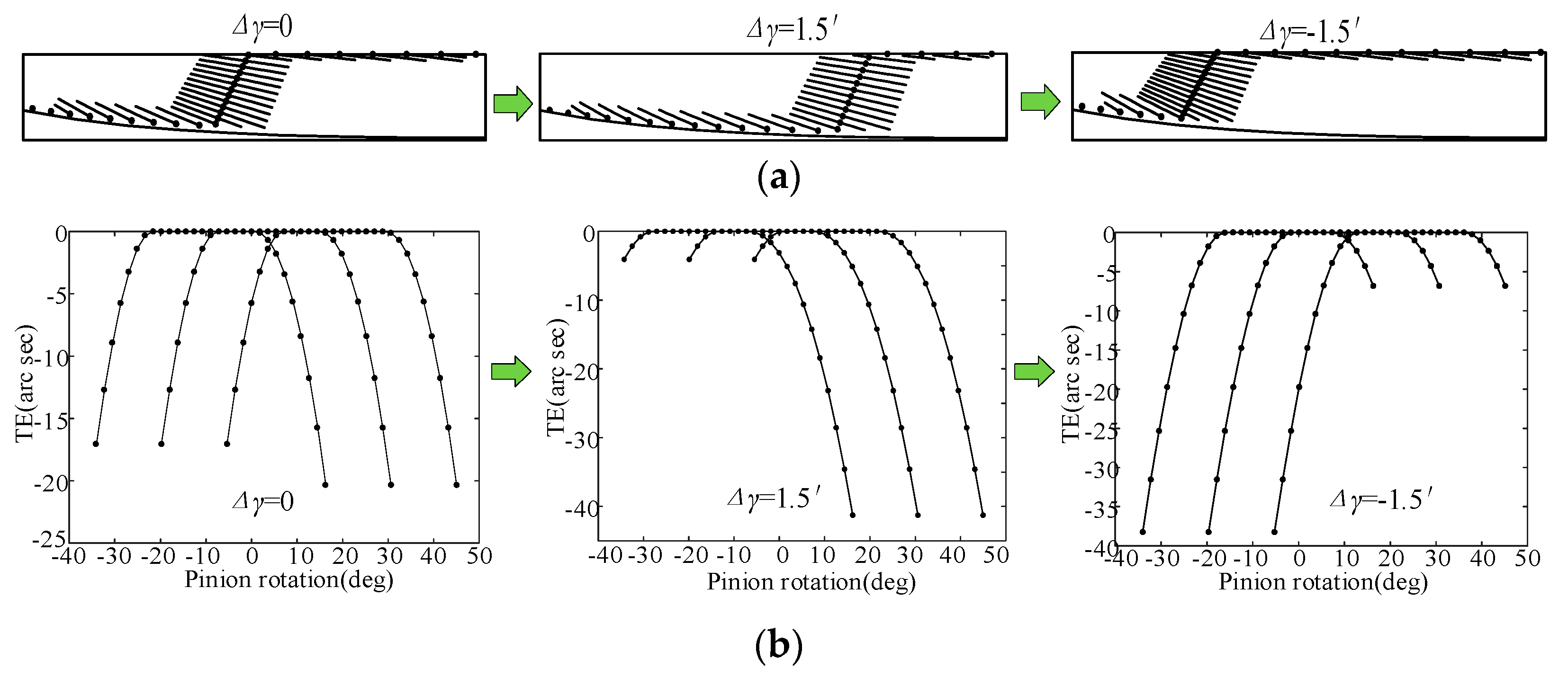
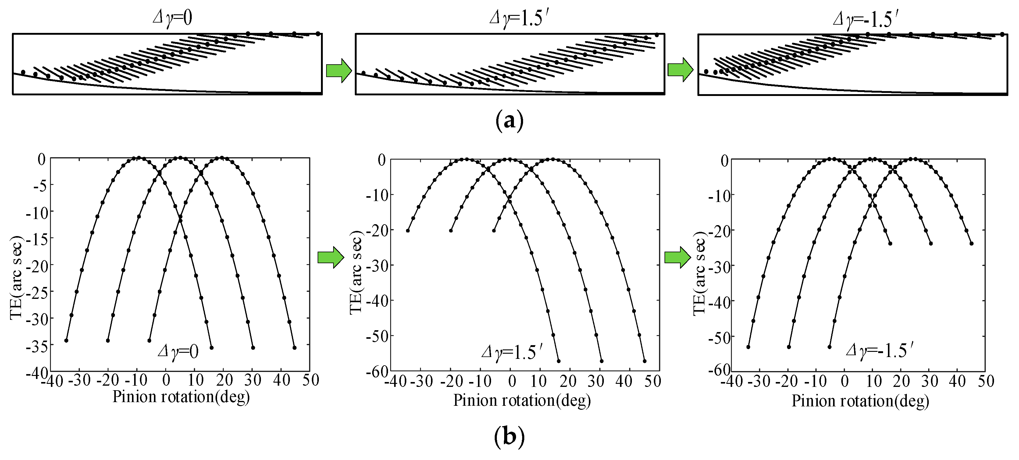
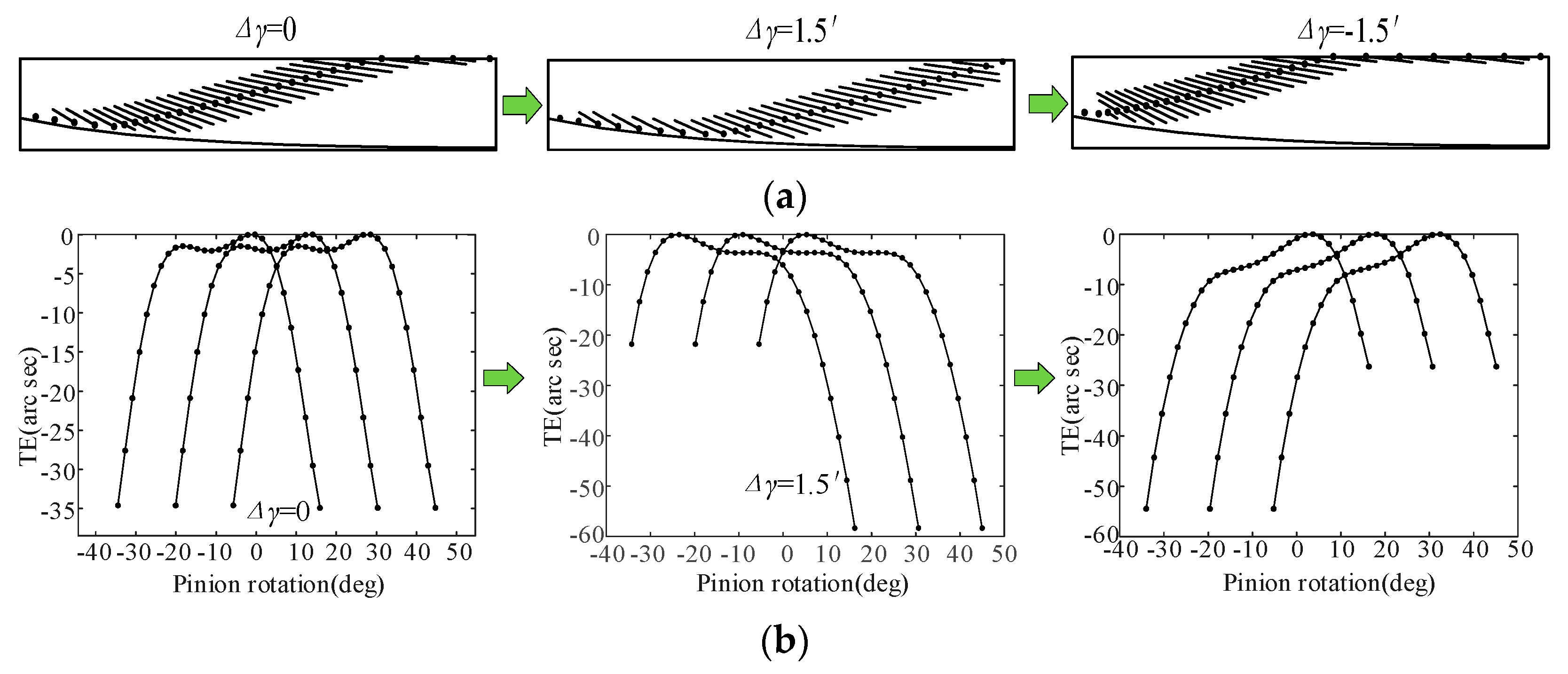
5.2. Tooth Contact Analysis

The contact pattern and the transmission error can be obtained from the TCA calculation. The contact pattern is the main characteristic target of the process of designing, machining, testing, and other related processes due to its intuitiveness, and it is also the key index to measure the transmission and meshing performance of the face gears.
As shown in Figure 14, the TCA calculation results of non-mod, tra-mod, and nov-mod without misalignment error are given. It can be found that the transmission error increases after tooth modification. Furthermore, there are more contact points on the tooth surface, which means that the contact ratio of the face gears increases after the tooth modification. In addition, after tooth modification, the original tooth surface meshing line contact is changed to point contact, so the error sensitivity is reduced. Figure 15 show simplified face gear and pinion transmission models, where Δq is the axial mounting error, ΔE is the offset mounting error, and Δγ is the misalignment error. The misalignment error has the most significant effect on the face gear TCA results; therefore, this paper focuses on the misalignment error. Figure 16, Figure 17 and Figure 18 show the variations in the contact pattern and transmission error with the misalignment error for non-mod, tra-mod, and nov-mod, respectively. Compared to the standard installation situation (Δγ = 0), when Δγ = 1.5′, the position of the tooth surface contact point of the face gear continues to shift toward the outer end position, the tooth top edge contact points decrease, the tooth root edge contact points increase, and the meshing position increases. The transmission error also increases significantly. When Δγ = −1.5′, the position of the tooth surface contact point continues to shift toward the inner end position, the tooth root edge contact points decrease, the tooth top edge contact points increase, and the transmission error at the meshing position also increases significantly.
However, judging from the calculation results of TCA alone, the advantages of the nov-mod are not shown. Therefore, further LTCA of face gears is required to further analyze the loaded meshing performance of the nov-mod.

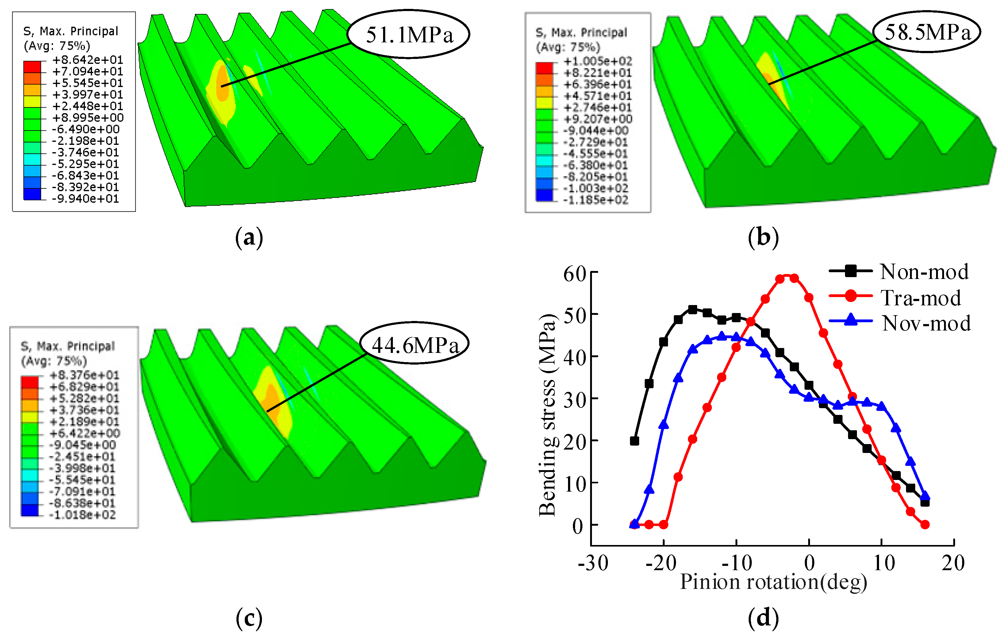
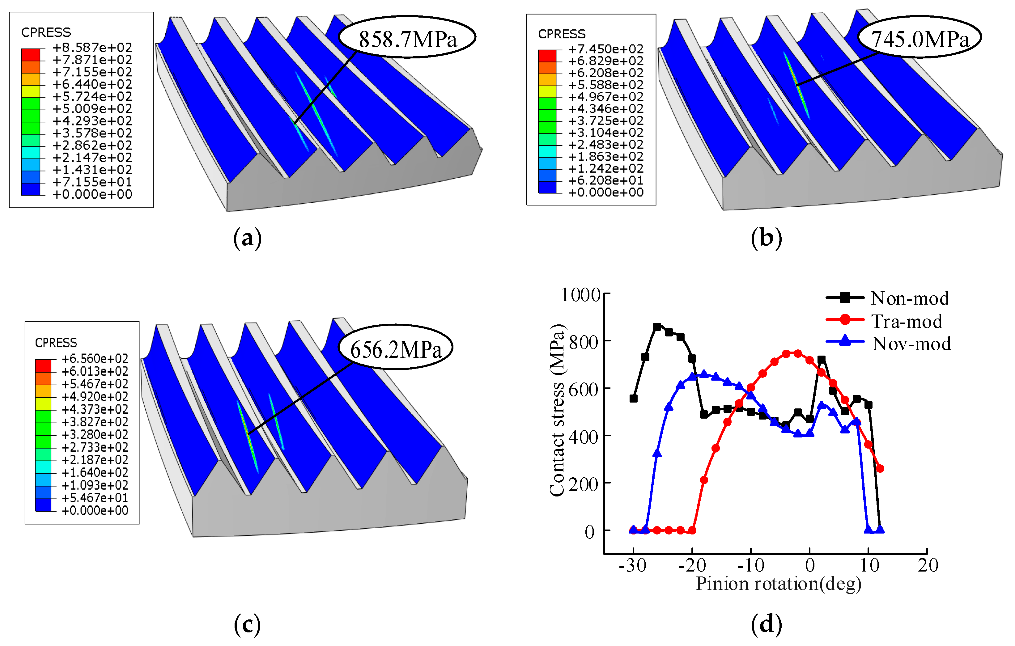
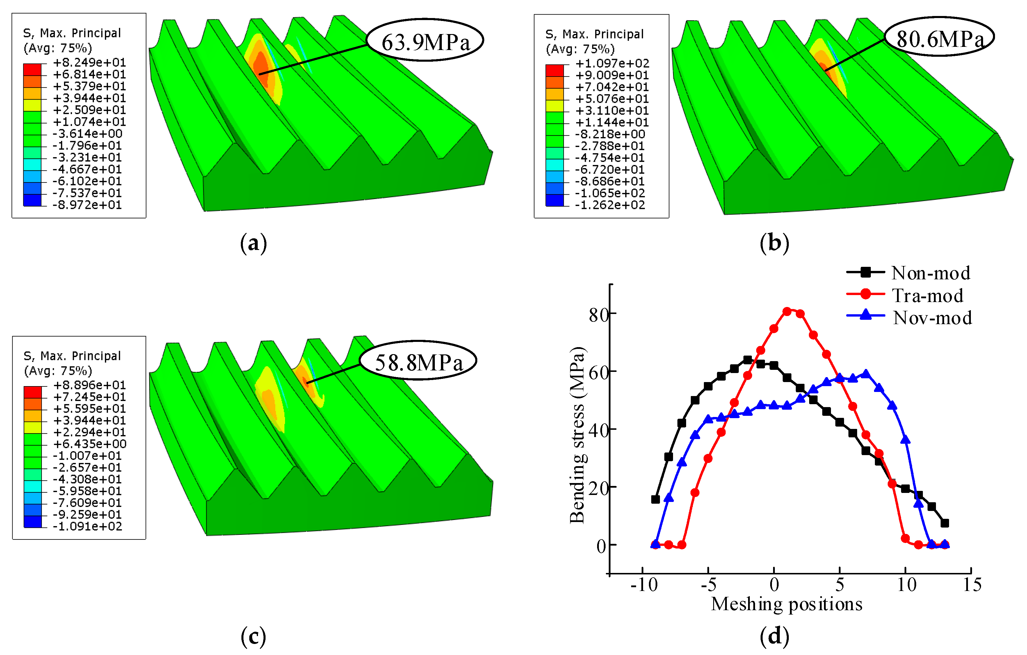
5.3. Loaded Tooth Contact Analysis

Using ABAQUS software (2021), we conducted a finite element simulation analysis on the non-orthogonal helical tooth surface gear transmission to obtain the contact stress and bending stress when the gear teeth are in contact, thereby judging the performance of the new method of cultivating the subsequent gear transmission. The magnitude of the force applied in this analysis was 1600N∙m.
Figure 19 shows the contact stress comparison of non-mod, tra-mod, and nov-mod without misalignment error. Figure 19a–c shows the contact stress nephograms of non-mod, tra-mod, and nov-mod at the position of the pitch circle. It can be seen from the stress nephogram that the contact stress increases after the tooth modification. This is because before tooth modification, the gears are in line contact, but after tooth modification, the gears become point contact, so the contact stress increases. However, it can also be seen that the contact stress of the nov-mod is smaller than that of the tra-mod. This is because the nov-mod makes the load on the tooth surface more consistent and improves the load distribution.
Figure 19d shows the contact stress comparison of the three types of tooth surfaces during the whole process from the gear teeth entering the mesh to exiting the mesh. It can be seen from the figure that when entering and exiting the mesh, the contact stress of the non-mod is relatively large because the contact line of the gears is relatively short in these two areas. The maximum contact stress of the non-mod is 890.7 MPa. After tooth modification, the center of the tooth surface experiences an increase in contact stress while the border of the tooth surface experiences a decrease in contact stress. Therefore, tooth modification is beneficial to gear transmission. However, it can also be seen in Figure 19d that the contact stress of the tra-mod in the middle area of the tooth surface increases sharply. The maximum contact stress of the tra-mod is 739.7 MPa. By comparing the contact stress of the nov-mod with that of the tra-mod, the advantages of the nov-mod are shown. The maximum contact stress of the nov-mod is 580.4 MPa. Compared to the tra-mod, the maximum contact stress of the nov-mod is reduced by 34.83%.
Figure 20 illustrates the bending stress comparison of non-mod, tra-mod, and nov-mod without misalignment error. Figure 20a–c shows the bending stress nephograms of non-mod, tra-mod, and nov-mod at the position of the pitch circle. It can be seen in the figures that the tooth modification also has a great influence on the bending stress of the gears. Tooth modification changes the load distribution on the tooth surface and then affects the bending stress of the gears. Figure 20d shows the contact stress comparison of the three types of tooth surfaces during the whole process from the gear teeth entering the mesh to exiting the mesh. In the figure, the maximum bending stresses of the non-mod, tra-mod, and nov-mod are 51.1 MPa, 58.5 MPa, and 44.6 MPa, respectively. Similar to the contact stress, additionally, the nov-mod’s bending stress is lower than the tra-mod’s, with a decrease of up to 12.72%. The maximum contact stress and maximum bending stress without misalignment errors are shown in Table 2.
It is well-known that errors in assembly and manufacturing are unavoidable in actual conditions. Therefore, the influence of the misalignment error on the meshing performance of face gears are studied below.
Figure 21 shows the contact stress comparison of non-mod, tra-mod, and nov-mod with misalignment error Δγ = 1.5′. Figure 21d shows the contact stress comparison of the three types of tooth surfaces during the whole process, from the gear teeth entering the mesh to exiting the mesh. The maximum contact stress of non-mod is 858.7 MPa. After tooth modification, the center of the tooth surface experiences an increase in contact stress, while the border of the tooth surface experiences a decrease in contact stress. Therefore, tooth modification is beneficial to gear transmission. However, it can also be seen from Figure 21d that the contact stress of the tra-mod in the middle area of the tooth surface increases sharply. The maximum contact stress of tra-mod is 745.0MPa. By comparing the contact stress of the nov-mod with that of the tra-mod, the advantages of the nov-mod are shown. The maximum contact stress of the nov-mod is 656.2 MPa. Compared to the tra-mod, the maximum contact stress of the nov-mod is reduced by 23.58%.
Figure 22 illustrates the bending stress comparison of non-mod, tra-mod, and nov-mod with misalignment error Δγ = 1.5′. Figure 22d shows the contact stress comparison of the three types of tooth surfaces during the whole process, from the gear teeth entering the mesh to exiting the mesh. In the figure, the maximum bending stresses of non-mod, tra-mod, and nov-mod are 56.4 MPa, 58.5 MPa, and 47.7 MPa, respectively. Similar to the contact stress, with a decrease of up to 15.42%, the bending stress of the nov-mod is also lower than that of the tra-mod. The maximum contact stress and maximum bending stress with misalignment error Δγ = 1.5′ are shown in Table 3.

6. Conclusions

This paper proposes a new gear modification method to improve the load-bearing capacity of non-orthogonal helical gears and draws the following conclusions from the current research:
(1)
This paper proposes a new bidirectional gear modification method. The tooth modification is determined by the modified rack-cutter, and its feed motion is related to an intentionally designed transmission error. The novelty of the tooth modification design is that the transmission error can be predesigned.
(2)
The performance of the introduced novel tooth modification is studied through TCA and LTCA. Under the non-misalignment error working conditions, the contact stress and bending stress of the novel tooth modification decrease by as much as 34.83% and 12.72%, which shows better meshing performance compared to the traditional tooth modification.
(3)
Under the misalignment error working conditions, the contact stress and bending stress of the novel tooth modification decrease by as much as 26.24% and 7.98%. The introduced new gear modification method has lower tooth profile contact stress and tooth root bending stress both with and without misalignment errors.
(4)
The introduced novel tooth modification in this paper is universal, and not limited to face gears but can be extended to other types of gears.

Author Contributions

Conceptualization, C.J.; methodology, C.J.; software, J.X.; validation, B.L.; formal analysis, B.L.; investigation, B.L.; resources, C.J.; data curation, B.L.; writing—original draft preparation, B.L.; writing—review and editing, C.J.; visualization, B.L.; supervision, C.J.; project administration, C.J.; funding acquisition, C.J. and B.L. All authors have read and agreed to the published version of the manuscript.

Funding

The work described in this paper was supported by the National Natural Science Foundation of China (Project Nos. 52375044, 52005107), the Fujian Provincial Science and Technology Major Special Projects (Project No. 2021HZ024006), and the Natural Science Foundation of Fujian Province, China (Project No. 2020J05100).

Institutional Review Board Statement

Not applicable.

Informed Consent Statement

Not applicable.

Data Availability Statement

Data are contained within the article.

Conflicts of Interest

The authors declare that they have no known competing financial interests or personal relationships that could have appeared to influence the work reported in this paper.

Nomenclature

a1modification parameter for tooth profile modification
Sicoordinate system i
ui, lisurface parameter of ∑i
[M]i,jcoordinate transmission matrix (from Sj to Si)
r i , n i position vector and unit normal vector of surface ∑i
βbase helix angle
ΔL1parameter of additional translation motion of rack-cutter
Δγmisalignment angle error
δφ2transmission error
θ1rotation angle of generated pinion
p0maximum contact stress
φ1, φ2rotation angle of pinion and face gear
Abbreviations
Nov-modnovel modification
Non-modnon-modification
Tra-modtraditional modification
TEtransmission error

References

  1. He, Z.; Lin, H.; Han, X. Computerized design and simulation of meshing of modified double circular-arc helical gears by tooth end relief with helix. Mech. Mach. Theory 2010, 45, 46–64. [Google Scholar]
  2. Chapron, M.; Velex, P.; Bruyère, J.; Becquerelle, S. Optimization of Profile Modifications with Regard to Dynamic Tooth Loads in Single and Double-Helical Planetary Gears with Flexible Ring-Gears. J. Mech. Des. 2016, 138, 023301. [Google Scholar] [CrossRef]
  3. Tran, V.-Q.; Wu, Y.-R. A novel method for closed-loop topology modification of helical gears using internal-meshing gear honing. Mech. Mach. Theory 2019, 145, 103691. [Google Scholar] [CrossRef]
  4. Deng, J.; Nie, S.; Deng, X.; Jiang, C. Tooth surface mismatch modification method of cycloidal bevel gear based on conjugate tooth surface modification. J. Adv. Mech. Des. Syst. Manuf. 2020, 14, JAMDSM0017. [Google Scholar] [CrossRef]
  5. Li, T.; An, X.; Deng, X.; Li, J.; Li, Y. A New Tooth Profile Modification Method of Cycloidal Gears in Precision Reducers for Robots. Appl. Sci. 2020, 10, 1266. [Google Scholar] [CrossRef]
  6. Wang, H.; Tang, L.; Zhou, C.; Shi, Z. Wear life prediction method of crowned double helical gear drive in point contact mixed elas-tohydrodynamic lubrication. Wear 2021, 484, 204041. [Google Scholar] [CrossRef]
  7. Feng, Z.; Chen, Y.; Zhao, Y. Analysis of Influence of Pinion Tooth Trace Modification on Tooth Surface of Curved Tooth Face Gear. Mech. Transm. 2022, 46, 50–55. [Google Scholar]
  8. Huangfu, Y.; Zhao, Z.; Ma, H.; Han, H.; Chen, K. Effects of tooth modifications on the dynamic characteristics of thin-rimmed gears under surface wear. Mech. Mach. Theory 2020, 150, 103870. [Google Scholar] [CrossRef]
  9. Yang, J.; Lin, T.; He, Z.; Chen, M. Novel calculation method for dynamic excitation of modified double-helical gear transmission. Mech. Mach. Theory 2022, 167, 104467. [Google Scholar] [CrossRef]
  10. Ren, Z.Y.; Mao, S.M.; Guo, W.C.; Guo, Z. Tooth modification and dynamic performance of the cycloidal drive. Mech. Syst. Signal Process. 2017, 85, 857–866. [Google Scholar] [CrossRef]
  11. Zschippang, H.; Weikert, S.; Küçük, K.; Wegener, K. Face-gear drive: Geometry generation and tooth contact analysis. Mech. Mach. Theory 2019, 142, 103576. [Google Scholar] [CrossRef]
  12. Dongsheng, H. Research on Numerical Analysis Modeling Method for Gear Meshing and Its Applications; Dalian University of Technology: Dalian, China, 2012. [Google Scholar]
  13. Yunbo, S. Novel Design Process for Face Gear Drive with a High Order Polynomial Function of Transmission Error. J. Xi’an Technol. Univ. 2013, 33, 7. [Google Scholar]
  14. Li, D.; Wu, S.; Zhao, R.; Deng, X. Design of the high-order curve tooth profile and analysis on the face gear’s tooth contact. Mech. Des. 2020, 37, 109–114. [Google Scholar]
  15. Fu, X.; Fang, Z.; Cui, Y.; Hou, X.; Li, J. Modelling, design and analysis of offset, non-orthogonal and profile-shifted face gear drives. Adv. Mech. Eng. 2018, 10, 1687814018798250. [Google Scholar] [CrossRef]
  16. Fu, X.; Fang, Z.; Xiang, L.; Li, J. Assembly errors tolerance and sensitivity of offset face gears. J. Harbin Eng. Univ. 2018, 39, 1227–1232. [Google Scholar]
  17. Feng, G.; Xie, Z.; Zhou, M. Geometric design and analysis of face-gear drive with involute helical pinion. Mech. Mach. Theory 2019, 134, 169–196. [Google Scholar] [CrossRef]
  18. Wang, C. Multi-objective optimal design of modification for helical gear. Mech. Syst. Signal Process. 2021, 157, 107762. [Google Scholar] [CrossRef]
  19. Gao, P.; Liu, H.; Yan, P.; Xie, Y.; Xiang, C.; Wang, C. Research on application of dynamic optimization modification for an involute spur gear in a fixed-shaft gear transmission system. Mech. Syst. Signal Process. 2022, 181, 109530. [Google Scholar] [CrossRef]
  20. Zheng, F.; Zhang, M.; Zhang, W.; Tan, R.; Guo, X. On the deformed tooth contact analysis for forged bevel gear modification. Mech. Mach. Theory 2019, 135, 192–207. [Google Scholar] [CrossRef]
  21. Yuan, B.; Liu, G.; Yue, Y.; Liu, L.; Shen, Y. A novel tooth surface modification methodology for wide-faced double-helical gear pairs. Mech. Mach. Theory 2021, 160, 104299. [Google Scholar] [CrossRef]
  22. Yan, P.; Liu, H.; Gao, P.; Zhang, X.; Zhan, Z.; Zhang, C. Optimization of distributed axial dynamic modification based on the dynamic characteristics of a helical gear pair and a test verification. Mech. Mach. Theory 2021, 163, 104371. [Google Scholar] [CrossRef]
  23. Yang, Y.C.; Wu, Y.R.; Tsai, T.M. An analytical method to control and predict grinding textures on modified gear tooth flanks in CNC generating gear grinding. Mech. Mach. Theory 2022, 177, 105023. [Google Scholar] [CrossRef]
  24. Jiang, Y.; Chen, Z.; Tong, S.; Li, S.; Tong, Z. Gear tribodynamic modeling and analysis considering tooth profile modification. Tribol. Int. 2023, 178, 108023. [Google Scholar] [CrossRef]
  25. Su, J.; Fang, Z.; Cai, X. Design and analysis of spiral bevel gears with seventh-order function of transmission error. Chin. J. Aeronaut. 2013, 26, 1310–1316. [Google Scholar] [CrossRef]
  26. Jiang, J.; Fang, Z. Design and analysis of modified cylindrical gears with a higher-order transmission error. Mech. Mach. Theory 2015, 88, 141–152. [Google Scholar] [CrossRef]
  27. Jia, C.; Fang, Z.; Zhang, Y. Topography of modified surfaces based on compensated conjugation for the minimization of trans-mission errors of cylindrical gears. Mech. Mach. Theory 2017, 116, 145–161. [Google Scholar] [CrossRef]
  28. Yu, B.; Ting, K.L. Compensated conjugation and gear tooth design and modification. J. Mech. Des. 2016, 138, 073301. [Google Scholar] [CrossRef]
  29. Yang, J.; Shi, Z.; Zhang, H.; Li, T.; Nie, S.; Wei, B. Dynamic analysis of spiral bevel and hypoid gears with high-order transmission errors. J. Sound Vib. 2018, 417, 149–164. [Google Scholar] [CrossRef]
  30. Mu, Y.; Li, W.; Fang, Z.; Zhang, X. A novel tooth surface modification method for spiral bevel gears with higher-order transmission error. Mech. Mach. Theory 2018, 126, 49–60. [Google Scholar] [CrossRef]
  31. Samani, F.S.; Molaie, M.; Pellicano, F. Nonlinear vibration of the spiral bevel gear with a novel tooth surface modification method. Meccanica 2019, 54, 1071–1081. [Google Scholar] [CrossRef]
  32. Korta, J.A.; Mundo, D. Multi-objective microgeometry optimization of gear teeth supported by response surface methodology. Mech. Mach. Theory 2017, 109, 278–295. [Google Scholar] [CrossRef]
  33. Lu, G.; Fan, S.; Li, G.; Tong, S.; Xiao, R. Research on Design and Pitch surface shape of New Type High-order Non-conical gears. Chin. Mech. Eng. 2015, 26, 2989–2995. [Google Scholar]
  34. Zhao, X.; Ye, J.; Chu, M.; Dai, L.; Chen, J. Automatic Scallion Seedling Feeding Mechanism with an Asymmetrical High-order Transmission Gear Train. Chin. J. Mech. Eng. 2020, 33, 10. [Google Scholar] [CrossRef]
  35. Litvin, F.L.; Fuentes, A. Gear Geometry and Applied Theory; Guo, K., Ye, L., Fan, L., Jr., Eds.; Shanghai Scientific and Technical Publishers: Shanghai, China, 2008; pp. 484–485. [Google Scholar]
  36. Vouaillat, G.; Noyel, J.P.; Ville, F.; Kleber, X.; Rathery, S. From Hertzian contact to spur gears: Analyses of stresses and rolling contact fatigue. Mech. Ind. 2019, 20, 626. [Google Scholar] [CrossRef]
  37. Guingand, M.; Vaujany, J.; Jacquin, C.Y. Quasi-static analysis of a face gear under torque. Comput. Methods Appl. Mech. Eng. 2005, 194, 4301–4318. [Google Scholar] [CrossRef]
Figure 1. Schematic diagram of face gear machining. (a) Front view; (b) side view.
Machines 11 01077 g001
Figure 2. Tooth profile of the rack-cutter. (a) Tooth profile schematic; (b) schematic diagram of helix angle; (c) machining schematic; (where s0 is the pitch of the round segment; α is the pressure angle of the rack-cutter; β 2 is the helix angle).
Machines 11 01077 g002
Figure 3. Generation of coordinate system for the disk grinding wheel. (a) Grinding wheel processing; (b) coordinate system machining.
Machines 11 01077 g003
Figure 4. Tooth profile modification renderings.
Machines 11 01077 g004
Figure 5. Tooth modification of the rack-cutter of pinion. (a) Second-order parabolic tooth profile; (b) schematic diagram of helix angle.
Machines 11 01077 g005
Figure 6. Generation of novel double-crowned tooth surface of pinion.
Machines 11 01077 g006
Figure 7. Face gear pair. (a) Face gears; (b) meshing coordinate systems of face gears.
Machines 11 01077 g007
Figure 8. Hertzian elastic contact.
Machines 11 01077 g008
Figure 9. The high-order parabolic transmission error.
Machines 11 01077 g009
Figure 10. The traditional second-order parabolic transmission error.
Machines 11 01077 g010
Figure 11. Face gear tooth models.
Machines 11 01077 g011
Figure 12. Pinion tooth models.
Machines 11 01077 g012
Figure 13. Tooth modification values of the pinion. (a) Tra-mod; (b) nov-mod.
Machines 11 01077 g013
Figure 14. Contact patterns and TEs of non-mod, tra-mod, and nov-mod without misalignment error. (a) Contact patterns; (b) TEs.
Machines 11 01077 g014
Figure 15. Simplified face gear and pinion transmission models.
Machines 11 01077 g015
Figure 16. Variations in contact pattern and TE of non-mod with misalignment error. (a) Contact pattern; (b) TEs.
Machines 11 01077 g016
Figure 17. Variations in contact pattern and TE of tra-mod with misalignment error. (a) Contact pattern; (b) TEs.
Machines 11 01077 g017
Figure 18. Variations in contact pattern and TE of nov-mod with misalignment error. (a) Contact pattern; (b) TEs.
Machines 11 01077 g018
Figure 19. Comparison of the contact stresses without misalignment error. (a) Non-mod; (b) tra-mod; (c) nov-mod; (d) comparison of contact stresses.
Machines 11 01077 g019
Figure 20. Comparison of the bending stresses without misalignment error. (a) Non-mod; (b) tra-mod; (c) nov-mod; (d) comparison of the bending stresses.
Machines 11 01077 g020
Figure 21. Comparison of the contact stresses with misalignment error, Δγ = 1.5′. (a) Non-mod; (b) tra-mod; (c) nov-mod; (d) comparison of the contact stresses.
Machines 11 01077 g021
Figure 22. Comparison of the bending stresses with misalignment error, Δγ = 1.5′. (a) Non-mod; (b) tra-mod; (c) nov-mod; (d) comparison of the contact stresses.
Machines 11 01077 g022
Table 1. Basic design parameters of a non-orthogonal helical face gear.
ParameterValue
Pinion tooth number25
Cutter tooth number28
Face gear tooth number160
Normal module (mm)6.35
Pressure angle (degree)25
Helix angle (degree)15
Shaft angle (degree)100
Inner radius (mm)510
External radius (mm)600
Table 2. Comparison of the maximum contact stress and maximum bending stresses without misalignment error.
ItemsContact StressBending Stress
Results (MPa)VariationResults (MPa)Variation
Non-mod890.751.1
Tra-mod739.7−16.95%58.5+14.48%
Nov-mod580.4−34.83%44.6−12.72%
Table 3. Comparison of the maximum contact stress and maximum bending stresses with misalignment error, Δγ = 1.5′.
ItemsContact StressBending Stress
Results (MPa)VariationResults (MPa)Variation
Non-mod940.963.9
Tra-mod774.2−17.73%80.6+26.13%
Nov-mod694.5−26.24%58.8−7.98%
Disclaimer/Publisher’s Note: The statements, opinions and data contained in all publications are solely those of the individual author(s) and contributor(s) and not of MDPI and/or the editor(s). MDPI and/or the editor(s) disclaim responsibility for any injury to people or property resulting from any ideas, methods, instructions or products referred to in the content.

