Abstract
This article investigates the comparison between two configurations of 20 MW offshore synchronous wind generators using ferrite and rare-earth permanent magnets. The optimization-based comparison concerns the torque ripple and active mass, which are two crucial criteria for offshore wind generators. Both generators adopt surface-mounted permanent magnet type with direct-drive technology to avoid problems associated with the gearboxes. The result shows that at the full-load condition, the ferrite permanent magnet generator can reduce the torque ripple to as much as 0.12%, while the rare-earth counterpart can be about 2.5 times lighter than the former one.
1. Introduction
In various countries, renewable energy has recently witnessed a considerable proliferation in response to climate change and fossil fuels being exhausted to reach the goal of emission reduction set by the Paris Agreement. Thanks to its high potential, wind energy is gaining more and more attention with rapid technological advancement. Because offshore wind energy has a greater installed area, fewer surrounding barriers, and higher and more constant wind speeds than its onshore counterpart, it is a complementing energy source. The significantly high investment and operational costs are the main challenges to the development of offshore wind farms. With the same installed capacity, wind turbines with high nominal power are preferable to reduce the number of turbines, meaning that some costs such as the installation, operation, and maintenance can be reduced. However, the mass of some turbine components will be significantly increased, presenting difficulties in manufacturing, transportation, and installation [1].
Increasing the nominal power is a means to reduce the cost of energy. However, this will make longer blades, resulting in a lower shaft speed in the generator if direct-drive technology is used. Torque ripple, which is the torque fluctuation around its mean value, is worse at low speeds. Since torque ripple is one of the most critical concerns in high-performance applications, its direct effects on the generator, such as vibration, noises, and friction, can reduce the turbine’s performance and shorten its lifespan [2,3].
With a roughly 50% market share, the doubly fed induction generator is now the most widely used technology in the wind industry [4]. However, as the nominal power of wind generators is increasing, lightweight and compact-design generators are necessarily required. For high-nominal-power wind turbines, permanent magnet synchronous generators (PMSGs) have taken the lead in technology. The largest commercial turbine as of 2021 is a 16 MW turbine that will be launched in 2024 [5].
There are two commonly used materials for permanent magnets in PMSGs: rare-earth and ferrite. The rare-earth PM-based generator (RPMG) is advantageous in its impact and lighter design thanks to the high PM residual flux density. However, this increases the generator’s torque ripple due to the strong air-gap magnetic field, and the generator is more costly than the ferrite PM-based generator (FPMG). The comparison between these two types of PM is, therefore, essential. However, such a comparison for radial flux generators is limited, especially at high nominal power. In [6], authors compared these two direct-drive PM wind generators. The transverse flux PM types were adopted. The research analyses focused on operation principles, design procedure, and performance. It concluded that the ferrite PM candidate can have acceptable performance for low-cost wind turbine applications. Comparisons between direct-drive and geared wind generator concepts were conducted in [7], and the PMSG with surface-mounted rare-earth PM type was used. This research concluded that the PMSG is attractive regarding the annual energy yield. However, the counterpart with ferrite PM was not considered. In [8], authors compared the rare-earth and ferrite flux-switching types. It was found that the ferrite PM generator is supposed to be a good alternative to the rare-earth one with higher average efficiency. The mass of the ferrite PM generator is 2.4 times higher; however, its cost is approximately similar since the rare-earth magnets are much more expensive than ferrite ones. In [9], 10 kW flux-switching machines for a geared medium-speed wind generator using rare-earth and ferrite magnets were compared. Compared to the rare-earth PM generator, the ferrite one is able to save 35% active material cost but the torque density is 61.2% lower. A thorough analysis of the differences in performance between 10 kW rare-earth and non-rare-earth flux reversal wind generators was carried out in [10]. These generators have the PMs mounted on the stator pole shoe. It showed that the torque ripple for non-rare-earth generators is 64% lower than that of the rare-earth counterpart at the expense of a 2.6 times increase in mass. The research concluded that the non-rare-earth flux reversal wind generator is a practical alternative to the rare-earth one for medium-speed wind turbines with powers up to 10 kW.
This article will investigate the multi-objective optimization of a 20 MW PMSG direct-drive wind generator. Together with the torque ripple reduction, the active mass of the generator is another objective, as the light weight of the high-power wind generator is prioritized to lower the load put on the turbine’s tower and foundation. The reason for selecting such a high nominal power is that it aligns with the offshore wind turbine trend of rising nominal power and is thought to be in the ideal range for minimizing the levelized cost of energy [11]. The generator will be described and optimized using the particle swarm optimization (PSO) algorithm. The optimization-based comparison between RPMG and FPMG will be carried out. The article is organized as follows. Section 2 presents the methodology with details about the generator’s topology and a brief comparison between RPMG and FPMG. The results based on the particle swarm optimization are discussed in Section 3, followed by the conclusion in Section 4.
2. Methodology
2.1. Generator Configuration
In this research, the surface-mounted PM radial flux generator is chosen to mitigate the torque ripple and its associated noise compared to the interior PM type [12]. Although the interior PMSG releases a higher power factor and less copper loss [13], the surface-mounted PMSG is better suited for large wind turbines to boost the generator’s efficiency [14]. The wind energy conversion system is shown in Figure 1; the direct-drive technology is used by directly coupling the generator’s shaft to the blade hub. A step-up transformer and a back-to-back converter are used to interface the generator with the grid.
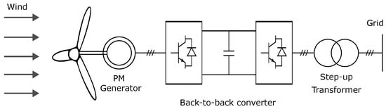
Figure 1.
Wind energy conversion system with direct-drive technology.
A double-layer winding configuration is adopted in the armature winding, which is preferable for direct-drive wind generators in terms of weight, cost, and torque ripple [15,16,17]. This article chooses a winding pitch factor of 5/6 to reduce the fifth and seventh harmonics. The one-pole-pair model is shown in Figure 2.
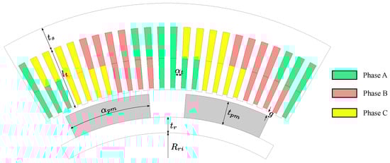
Figure 2.
Surface-mounted PMSG model.
The generator’s parameters are detailed in Table 1. Two permanent magnet types including rare-earth and ferrite ones with the corresponding residual flux densities of 0.4 T and 1.1 T will be used. The non-linear magnetization curve, displayed in Figure 3, will be employed for both stator and rotor cores. The generator’s nominal power is expressed by (1) [18].
where is the power coefficient, and is the tip speed ratio defined as defined by (2). In this article, to maximize the captured wind power, and are chosen to be equal to 0.48 and 7, respectively.
where is the blade length, and is the blade’s angular speed, which is the same as the speed of the generator’s shaft thanks to the direct-drive configuration.

Table 1.
Main design parameters of the generators.
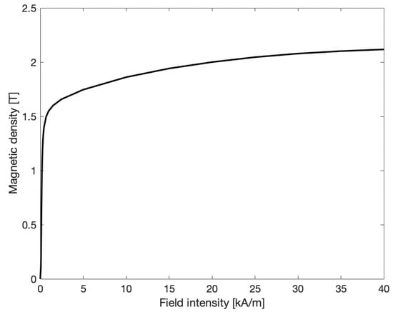
Figure 3.
Magnetization curve of the core material for the stator and rotor.
For structural optimization, the particle swarm optimization (PSO), which will be discussed later, will be used. Nine optimization variables are summarized in Table 2.
Table 2.
Design variables of the generators.
The aspect ratio , defined as the ratio between the generator’s axial length and its air-gap diameter, as in (3), strongly influences the generator’s total mass. Though the generator’s inactive mass is not taken into account in this research, it is considered as a design variable varying between 0.2 and 0.27, as recommended in [19].
The suggested mechanical air-gap length g for multi-megawatt generators is 1/1000 of the rotor diameter but not less than 3 mm, as in (4) [20].
2.2. Torque Ripple
An electrical machine’s instantaneous electromagnetic torque is made up of two parts: the mean torque and the periodic component, which is a function of time or the rotor’s position [21]. The periodic component causes torque ripple and can be calculated by (5) [21].
where and are maximum and minimum instant torques, respectively, and is the mean torque.
In this article generators are modeled by the 2-D finite element method (FEM) using ANSYS Electronics. In this software package, the FEM model is presented in a text-data form; therefore, it can be accessed and modified easily with MATLAB. Moreover, thanks to the capability of ANSYS running in a batch mode without a graphical interface (BatchExtract) using a Python script, this allows an effective coupling between MATLAB and ANSYS. In ANSYS, the instantaneous electromagnetic torque is computed by the virtual work approach that at a constant current, electromagnetic torque is equal to the derivative of the magnetic co-energy with respect to rotor angle, as in (6) [22]. For finite-element analyses, this method is frequently utilized to calculate magnetic force distributions because of its benefits, which include high accuracy and the requirement to compute only one field solution.
where is the flux linkage, is the phase current, is the stored magnetic energy, and is rotor angle.
The torque ripple can be divided into two main parts: the load-dependent torque pulsation that comes from the harmonic component of armature current and back-EMF [23], and the load-independent cogging torque that results from the interaction between the magnetic field of the PMs and the stator slot [24]. Cogging torque is a big concern in wind generators as it causes vibration and acoustic noises. It gradually reduces the generator’s performance, and shortens its lifespan [2].
2.3. Brief Comparison between RPMG and FPMG
As aforementioned, the RPMG has the advantage of high power density compared to the FPMG, and this reduces its size and mass. However, the air-gap flux density will increase, making the torque ripple of this generator higher than that of the FPMG. The analyses that follow will compare the two generators in terms of torque ripple, cogging torque, and air-gap flux density. A randomly chosen generator’s geometry, detailed in Table 3, will be used for those analyses. The no-load air-gap flux density comparison is shown in Figure 4. As can be seen, thanks to the strong magnetic field of the rare-earth PM, the air-gap flux density of the RPMG is much stronger than that of the FPMG. This explains the significantly high cogging torque of RPMG compared to that of the FPMG, as demonstrated in Figure 5.
Table 3.
Arbitrary design variables for a brief comparison between RPMG and FPMG.
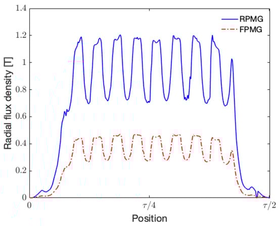
Figure 4.
Comparison of radial air-gap flux density between RPMG and FPMG at no-load condition. is the generator’s pole pitch.
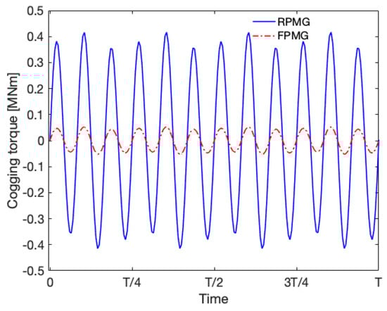
Figure 5.
Cogging torque comparison between RPMG and FPMG.
The torque comparison at the armature current of 1000 A is shown in Figure 6.
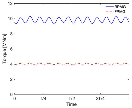
Figure 6.
Torque ripple comparison between RPMG and FPMG at the armature current of 1000 A (rms).
The torque ripples, computed by (5), for RPMG and FPMG are 5.14% and 2.33%, respectively. As mentioned, the advantage of the strong magnetic field with rare-earth PM is also the drawback that significantly increases its torque ripple.
3. Results and Discussion
3.1. Optimization Algorithm
In this article, multi-objective particle swarm optimization (MOPSO) will be used to minimize the generator’s torque ripple and mass. The optimization algorithm, which was first introduced in 1995 [25], is classified as a stochastic optimization technique that was developed using a simulation model studying the movement of schools of fish or flocks of birds. Every particle can follow both its own and the best population’s positions and velocities, acting as a potential solution to the optimization problem. Each individual has a fitness value assigned to them, and these values are used to determine their updated location and velocity. Until the equilibrium or optimal condition is reached, each individual’s states will be continuously adjusted inside the multi-dimensional search space [26,27]. When the maximum number of iterations is reached or the swarm radius drops below a particular small positive constant, the algorithm is terminated [28]. The method by which the particles’ position and velocity are updated is controlled by (7) and (8), respectively.
where is the inertial weight constant, and and are random numbers in the interval [0, 1] with uniform distribution. Constants and regulate the effect of the personal and global guides. and are personal best and global best, respectively. is 0.8 and and are 1 in this work.
The optimal location of each particle, , is determined by comparing its current position with its prior optimal position; on the other hand, the optimal solution of the swarm, , is determined by considering the set of non-dominated solutions updated in the preceding step. The particle swarm optimization’s basic flowchart is presented in Figure 7 [27]. In this article, the optimization stops once the predetermined number of iterations is reached.
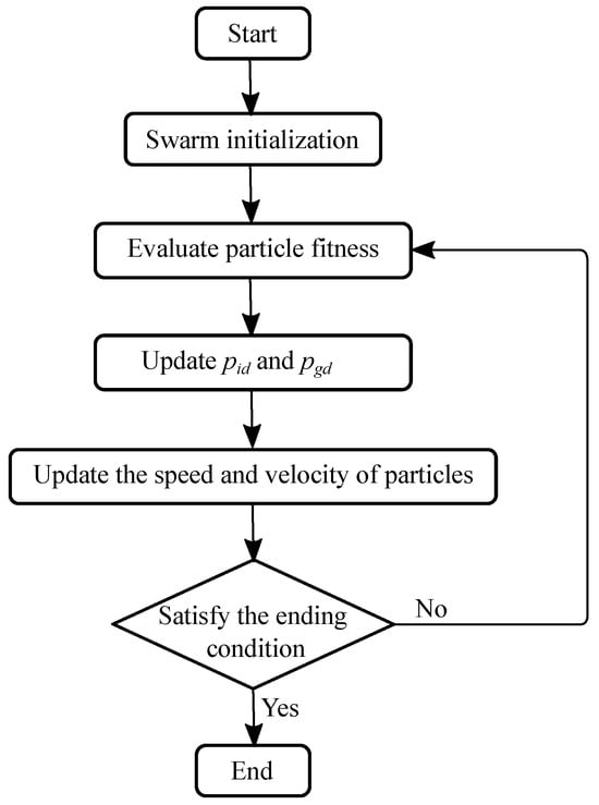
Figure 7.
PSO algorithm flowchart.
3.2. General Optimization Strategy
The optimization formulations are summarized in (9), where several constraints are to be applied. The maximum current density of 6 A/mm is imposed on the armature winding [29]. In addition, to enhance the design’s performance, the generator’s efficiency at the rated speed should be higher than 92% to be competitive [30].
There is a contradiction between the two optimization goals: reducing the torque ripple and mass of the generator because a larger generator may result in a smaller torque ripple. Larger magnetic air-gaps, for instance, can lessen an abrupt change in the flux density distribution of the air-gap, which in turn reduces the torque ripple. Larger air-gaps, however, result in a larger overall volume and mass of the generator. The overall mass is further increased by the need for more PM materials to maintain the air-gap flux density. The torque ripple and the mass may be influenced differently by other factors. For instance, extending the stator teeth will enhance the maximum current density by providing more space for the armature windings, but it will barely affect the torque ripple. The torque quality is not significantly affected by the stator and rotor yoke height because the air-gap flux density distribution is mainly independent of their thickness as long as they are not substantially saturated. The effects of several optimization variables on the cogging torque will be investigated first. Among variables, the stator tooth width and PM arc ratio are crucial ones because they have a direct impact on the flux density distribution in the generator’s air-gap.
There are essential influences on the torque quality from the PM width and the stator tooth width, which are related to the slot opening. One possible problem with the cogging torque amplitude is the decrease in slot opening width. When slot opening width is decreased, the air-gap permeance fluctuation may increase as a result of the local magnetic saturation boosted by tooth-tip leakage flux, leading to a greater cogging torque. However, as the slot opening is broadened, the variance in air-gap permeance increases, leading to an increase in torque ripple and cogging torque [31]. Additionally, the value of the relative PM width with the lowest ripple level is impacted by a bigger slot opening. As the slot opening width increases, the air-gap flux’s harmonics will also rise. These harmonics’ interaction with the space harmonics in the magneto-motive force will cause an increase in cogging torque and contribute to the torque ripple under load conditions. The latter harmonic component’s ripple can compensate for the cogging torque if the PM geometry is appropriately assigned, resulting in a smaller torque. Consequently, various load conditions will result in a change in saturation, meaning that the best design for the lowest cogging torque cannot achieve the minimal on-load torque ripple, and vice versa [32].
The influence of the stator tooth width and PM arc ratio on the cogging torque is investigated by varying one variable from 0.1 to 0.9 while the other remains constant. Variables and their values are summarized in Table 4.
Table 4.
Variables for the influence analysis of the tooth width and PM arc ratios.
The optimization results for RPMG and FPMG are reported in Figure 8a,b, respectively. The same setting parameters are used for both generator optimization: 432 and 50 iterations for the number of particles and iterations, accordingly. The dark symbols in each optimization result represent the final non-dominated solutions in the evolution (50 iterations) of the Pareto-fronts. In order to examine the convergence of the Pareto-fronts, the comparison between solutions at the 30th and 50th iterations for each generator is shown in Figure 9. As can be seen, not many differences are reported between the two orders of iteration for both generators.
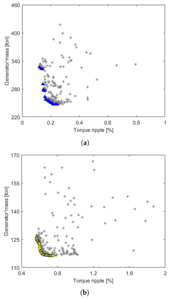
Figure 8.
Optimization results by Pareto-fronts. (a) FPMG result: Asterisk—all solutions through iterations. Triangle—Solutions of the last iteration. (b) RPMG result: Asterisk—all solutions through iterations. Circle—Solutions of the last iteration.
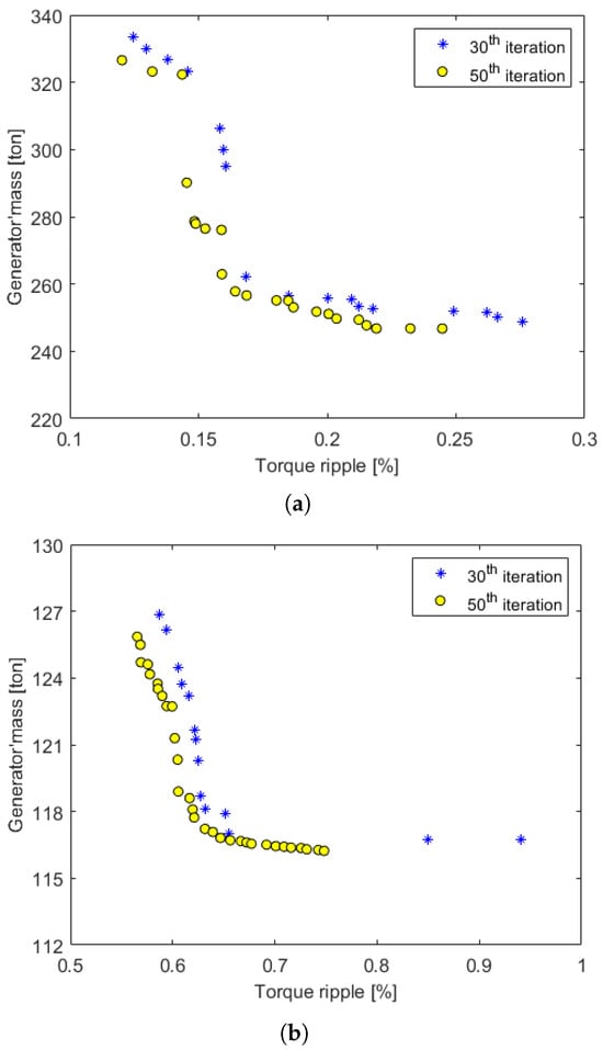
Figure 9.
Comparison of the Pareto-fronts at 30th and 50th iterations. (a) FPMG. (b) RPMG.
The optimal Pareto-front comparison between RPMG and FPMG is displayed in Figure 10. There are 31 optimal solutions presented in the Pareto-front set of RPMG and 22 optimal generators for FPMG. In each Pareto-front, two solutions at the two extreme points are marked: one with the lowest torque ripple (F1 for FPMG and R1 for RPMG) and the other with the smallest mass (F2 for FPMG and R2 for RPMG). Overall information on these four generators is summarized in Table 5.
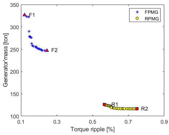
Figure 10.
Optimization results by non-dominated Pareto-front. Red triangles F1 and F2: FPMG solutions with the lowest torque ripple and mass, respectively. Red squares R1 and R2: RPMG solutions with the lowest torque ripple and mass, respectively.
Table 5.
Summary of four generators marked in Figure 10.
It is clearly shown that the FPMG is capable of reducing the torque ripple as the magnetic field in the air-gap is weaker compared to that of the RPMG. This requires a bigger machine, resulting in an increase in its mass. The bigger air-gap in the FPMG is also a reason for reducing its torque ripple. The air-gap length calculated by (4) will be longer when the machine is larger (see Table 5).
On these results, four specific generators, shown in Figure 11, are extracted for further analyses. The detailed design parameters of those generators are reported in Table 6. As can be seen, thanks to the high power density of rare-earth PM, the RPMG is much smaller in size compared to that of the FPMG. The axial lengths and outer diameters of those generators are also summarized in Table 6. Figure 12 shows the comparison between generators’ torque profiles. Due to the same power constraint of 20 MW imposed on all generators, the torques are very close to the mean values, which are 30.3 MNm.
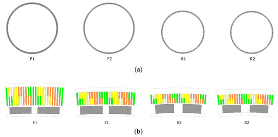
Figure 11.
Four generators marked in Figure 10. (a) Overall generator. (b) Models with one pole pair.
Table 6.
Design parameters of the four extracted generators.
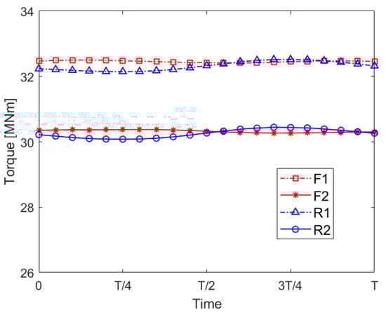
Figure 12.
Torque ripple comparison of the four extracted generators.
The four generators’ cogging torque comparison is displayed in Figure 13 and their values with other performance indicators are summarized in Table 7. Additionally, the cogging torque is computed and displayed as a percentage of the mean torque; results exhibit a relatively low value in comparison to the recommended ratio of 2%, as in [33]. Having a low cogging torque for a PM wind generator would be beneficial for the cut-in wind speed, the speed where the torque produced by the wind overcomes the generator’s cogging torque and starts to move the rotor blades. As a result, the annual energy yield of the wind turbine is increased.
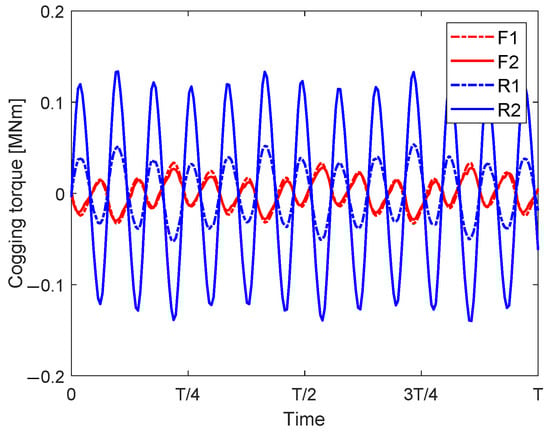
Figure 13.
Cogging torque comparison of the four extracted generators.
Table 7.
Torque and efficiency of the four extracted generators.
In addition to the comparison of torque quantities between generators, the overload capacity of four generators is investigated. Generators are usually designed with a high overload capacity to ensure a safe operation. In this analysis, the shaft speed remains constant (6.303 rpm), and the phase currents are varied between 0% and 400% of the rated value. The comparison, performed with per-unit values with respect to the nominal ones, between generators is demonstrated in Figure 14. The analysis shows a better overload capability of RPMG, which is about 30% higher at the current 400% of its rated value.
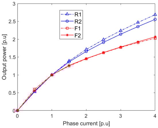
Figure 14.
Overload capacity comparison of the four extracted generators.
4. Conclusions
Optimizations to minimize both generator mass and torque ripple have been carried out for two types of wind generators using rare-earth and ferrite PMs. Due to the higher air-gap magnetic density, the rare-earth PM generator can reduce its mass to make it 2.5 times lighter compared to the ferrite PM one. However, this feature of the rare-earth PM also creates a higher torque ripple compared to that of the ferrite PM generator. By using ferrite PMs, the torque ripple can be lowered to as much as 0.12%, which is far below the recommended limit in the literature. Such a significantly low torque ripple of the ferrite PM generator would cause less mechanical fatigue for the generator. Therefore, the system’s reliability and the generator’s lifespan are improved. For offshore wind farms using very high-power turbines installed far from shore, this aspect becomes more and more important, as the maintenance time and cost can be significantly reduced. The comparison was made at the specific nominal power of 20 MW; however, similar comparisons for mass and torque ripple are believed to be applicable for another range of the turbine’s power. However, it should be noted that increasing the turbine’s power to a higher level would be very challenging, as the mass and volume of the turbine’s blades will be significantly increased. It is important to note that only the generator’s active mass was considered in this research and it solely accounts for a portion of the whole generator. The generator’s inactive mass was partly taken into account via the aspect ratio . For a more comprehensive result, additional analysis taking into account the inactive mass calculation will be considered. Furthermore, a rule of thumb to define the air-gap length of a multi-megawatt generator (1/1000 of the rotor diameter but not less than 3 mm) was applied in this article, which might influence the result due to its apparent influence on the air-gap magnetic density distribution. This concept is worth studying for future research.
Author Contributions
Conceptualization, T.-K.H. and L.V. All authors contributed to the methodology. Software, T.-K.H. and C.T. All authors contributed to the validation. Formal analysis, T.-K.H. Investigation, L.V. Resources, T.-K.H. Data curation, T.-K.H. and C.T. All authors contributed to the writing of the paper and the final editing. Visualization, T.-K.H. Supervision, T.-K.H. Project administration, T.-K.H. and L.V. All authors have read and agreed to the published version of the manuscript.
Funding
This research received no external funding.
Data Availability Statement
Data are contained within the article.
Conflicts of Interest
The authors declare no conflict of interest.
Abbreviations
The following abbreviations are used in this manuscript:
| PM | Permanent magnet |
| PMSG | Permanent magnet synchronous generator |
| PSO | Particle swarm optimization |
| MOPSO | Multi-objective particle swarm optimization |
| RPMG | Rare-earth PM-based generator |
| FPMG | Ferrite PM-based generator |
| FEM | Finite element method |
References
- Van Kuik, G.A.M.; Peinke, J.; Nijssen, R.; Lekou, D.; Mann, J.; Sørensen, J.N.; Ferreira, C.; van Wingerden, J.W.; Schlipf, D.; Gebraad, P.; et al. Long-term research challenges in wind energy—A research agenda by the European Academy of Wind Energy. Wind. Energy Sci. 2016, 1, 1–39. [Google Scholar] [CrossRef]
- Chu, W.Q.; Zhu, Z.Q. Investigation of Torque Ripples in Permanent Magnet Synchronous Machines With Skewing. IEEE Trans. Magn. 2013, 49, 1211–1220. [Google Scholar] [CrossRef]
- Yasa, Y.; Mese, E. Design and analysis of generator and converters for outer rotor direct drive gearless small-scale wind turbines. In Proceedings of the 2014 International Conference on Renewable Energy Research and Application (ICRERA), MilwaNuee, WI, USA, 19–22 October 2014; pp. 689–694. [Google Scholar] [CrossRef]
- Yaramasu, V.; Wu, B.; Sen, P.C.; Kouro, S.; Narimani, M. High-power wind energy conversion systems: State-of-the-art and emerging technologies. Proc. IEEE 2015, 103, 740–788. [Google Scholar] [CrossRef]
- Cooperman, A.; Duffy, P.; Hall, M.; Lozon, E.; Shields, M.; Musial, W. Assessment of Offshore Wind Energy Leasing Areas for Humboldt and Morro Bay Wind Energy Areas, California; Technical Report; National Renewable Energy Laboratory: Washington, DC, USA, 2022. [Google Scholar]
- Nasiri-Zarandi, R.; Karami-Shahnani, A.; Toulabi, M.S. Performance Comparison between Rare-Earth and Ferrite-based PM Transverse Flux Generators for Small-Scale Direct-Drive Wind Turbine. In Proceedings of the IECON 2021—47th Annual Conference of the IEEE Industrial Electronics Society, Toronto, ON, Canada, 13–16 October 2021; pp. 1–6. [Google Scholar] [CrossRef]
- Polinder, H.; van der Pijl, F.; de Vilder, G.J.; Tavner, P. Comparison of direct-drive and geared generator concepts for wind turbines. IEEE Trans. Energy Convers. 2006, 21, 725–733. [Google Scholar] [CrossRef]
- Prakht, V.; Dmitrievskii, V.; Kazakbaev, V.; Ibrahim, M.N. Comparison between rare-earth and ferrite permanent magnet flux-switching generators for gearless wind turbines. Energy Rep. 2020, 6, 1365–1369. [Google Scholar] [CrossRef]
- Akuru, U.B.; Kamper, M.J. Design and Investigation of Low-cost PM Flux Switching Machine for Geared Medium-speed Wind Energy Applications. Electr. Power Compon. Syst. 2018, 46, 1084–1092. [Google Scholar] [CrossRef]
- Bharathi, M.; Akuru, U.B.; Kumar, M.K. Comparative Design and Performance Analysis of 10 kW Rare-Earth and Non-Rare Earth Flux Reversal Wind Generators. Energies 2022, 15, 636. [Google Scholar] [CrossRef]
- Hoang, T.K.; Queval, L.; Vido, L.; Berriaud, C. Impact of the rotor blade technology on the levelized cost of energy of an offshore wind turbine. In Proceedings of the 2017 International Conference on Optimization of Electrical and Electronic Equipment (OPTIM) & 2017 Intl Aegean Conference on Electrical Machines and Power Electronics (ACEMP), Brasov, Romania, 25–27 May 2017; pp. 623–629. [Google Scholar] [CrossRef]
- Roshanfekr, P.; Thiringer, T.; Alatalo, M.; Lundmark, S. Performance of two 5 MW permanent magnet wind turbine generators using surface mounted and interior mounted magnets. In Proceedings of the 2012 XXth International Conference on Electrical Machines, Marseille, France, 2–5 September 2012; pp. 1041–1047. [Google Scholar] [CrossRef]
- Libert, F.; Soulard, J. Design Study of Different Direct-Driven Permanent-Magnet Motors for a Low Speed Application. In Proceedings of the Nordic Workshop on Power and Industrial Electronics (NORpie), Trondheim, Norway, 14–16 June 2004. [Google Scholar]
- Haraguchi, H.; Morimoto, S.; Sanada, M. Suitable design of a PMSG for a small-scale wind power generator. In Proceedings of the 2009 International Conference on Electrical Machines and Systems, Tokyo, Japan, 15–18 November 2009; pp. 1–6. [Google Scholar] [CrossRef]
- Chen, H.; Qu, R.; Li, J.; Zhao, B. Comparison of interior and surface permanent magnet machines with fractional slot concentrated windings for direct-drive wind generators. In Proceedings of the 2014 17th International Conference on Electrical Machines and Systems (ICEMS), Hangzhou, China, 22–25 October 2014; pp. 2612–2617. [Google Scholar]
- McDonald, A.; Bhuiyan, N.A. On the Optimization of Generators for Offshore Direct Drive Wind Turbines. IEEE Trans. Energy Convers. 2017, 32, 348–358. [Google Scholar] [CrossRef]
- Frosini, L.; Pastura, M. Analysis and Design of Innovative Magnetic Wedges for High Efficiency Permanent Magnet Synchronous Machines. Energies 2020, 13, 255. [Google Scholar] [CrossRef]
- Manwell, J.F.; Mcgowan, J.G.; Rogers, A.L. Wind Energy Explained; John Wiley & Sons, Ltd.: Hoboken, NJ, USA, 2010. [Google Scholar]
- Sethuraman, L.; Dykes, K. GeneratorSE: A Sizing Tool forVariable-Speed Wind TurbineGenerators; Technical Report; National Renewable Energy Laboratory: Washington, DC, USA, 2017. [Google Scholar]
- Grauers, A. Design of Direct-Driven Permanent Magnet Generators for Wind Turbines. Ph.D. Thesis, Chalmers University of Technology, Gothenburg, Sweden, 1996. [Google Scholar]
- Gieras, J.F.; Wang, C.; Lai, J.C. Noise of Polyphase Electric Motors; Taylor & Francis: Boca Raton, FL, USA, 2005. [Google Scholar]
- VuXuan, H.; Lahaye, D.; Ani, S.; Polinder, H.; Ferreira, J.A. Effect of design parameters on electromagnetic torque of PM machines with concentrated windings using nonlinear dynamic FEM. In Proceedings of the 2011 IEEE International Electric Machines and Drives Conference (IEMDC), Niagara Falls, ON, Canada, 15–18 May 2011; pp. 383–388. [Google Scholar] [CrossRef]
- Fei, W.; Luk, P.C.K. Torque Ripple Reduction of a Direct-Drive Permanent-Magnet Synchronous Machine by Material-Efficient Axial Pole Pairing. IEEE Trans. Ind. Electron. 2012, 59, 2601–2611. [Google Scholar] [CrossRef]
- Herlina; Setiabudy, R.; Rahardjo, A. Cogging torque reduction by modifying stator teeth and permanent magnet shape on a surface mounted PMSG. In Proceedings of the 2017 International Seminar on Intelligent Technology and Its Applications (ISITIA), Surabaya, Indonesia, 28–29 August 2017; pp. 227–232. [Google Scholar] [CrossRef]
- Kennedy, J.; Eberhart, R. Particle swarm optimization. In Proceedings of the ICNN’95—International Conference on Neural Networks, Perth, WA, Australia, 27 November–1 December 1995; Volume 4, pp. 1942–1948. [Google Scholar] [CrossRef]
- Reddy, M.J.; Kumar, D.N. Multi-objective Particle Swarm Optimization for Generating Optimal Trade-offs in Reservoir Operation. Hydrol. Process. 2007, 21, 2897–2909. [Google Scholar] [CrossRef]
- Wang, D.; Tan, D.; Liu, L. Particle swarm optimization algorithm: An overview. Soft Comput. 2018, 22, 387–408. [Google Scholar] [CrossRef]
- Baumgartner, U.; Magele, C.; Renhart, W. Pareto optimality and particle swarm optimization. IEEE Trans. Magn. 2004, 40, 1172–1175. [Google Scholar] [CrossRef]
- Sethuraman, L.; Maness, M.; Dykes, K. Optimized Generator Designs for the DTU 10-MW Offshore Wind Turbine Using GeneratorSE; Technical Report; National Renewable Energy Laboratory: Washington, DC, USA, 2017. [Google Scholar]
- Bergen, A.; Andersen, R.; Bauer, M.; Boy, H.; ter Brake, M.; Brutsaert, P.; Buhrer, C.; Dhalle, M.; Hansen, J.; ten Kate, H.; et al. Design and in-field testing of the worlds first ReBCO rotor for a 3.6 MW wind generator. Supercond. Sci. Technol. 2019, 32, 125006. [Google Scholar] [CrossRef]
- Zhu, Z.; Howe, D. Influence of design parameters on cogging torque in permanent magnet machines. IEEE Trans. Energy Convers. 2000, 15, 407–412. [Google Scholar] [CrossRef]
- Wu, D.; Zhu, Z. Design trade-off between cogging torque and torque ripple in fractional slot surface-mounted permanent magnet machines. In Proceedings of the 2015 IEEE International Magnetics Conference (INTERMAG), Beijing, China, 11–15 May 2015; p. 1. [Google Scholar] [CrossRef]
- Popescu, M.; Cistelecan, M.V.; Melcescu, L.; Covrig, M. Low Speed Directly Driven Permanent Magnet Synchronous Generators for Wind Energy Applications. In Proceedings of the 2007 International Conference on Clean Electrical Power, Capri, Italy, 21–23 May 2007; pp. 784–788. [Google Scholar]
Disclaimer/Publisher’s Note: The statements, opinions and data contained in all publications are solely those of the individual author(s) and contributor(s) and not of MDPI and/or the editor(s). MDPI and/or the editor(s) disclaim responsibility for any injury to people or property resulting from any ideas, methods, instructions or products referred to in the content. |
© 2023 by the authors. Licensee MDPI, Basel, Switzerland. This article is an open access article distributed under the terms and conditions of the Creative Commons Attribution (CC BY) license (https://creativecommons.org/licenses/by/4.0/).