1. Introduction
As thin-walled flexible structures easily vibrate and thereby radiate excessive noise, various vibration and noise reduction methods, in which applying damping treatments are of great importance, have been proposed and used in engineering. Free-layer damping (FLD) treatments [
1,
2,
3] and constraint-layer damping (CLD) treatments [
4,
5,
6] have been considered two of the main implementation methods, and these damping treatments have been widely used in engineering, including—but not limited to—aircraft skins, submarine hulls, and automobile panels [
7,
8,
9].
Due to its low cost, easy design, and high reliability, the FLD treatment has won the recognition of both researchers and engineers since it was introduced by Oberst [
10]. The FLD treatment is the most straightforward configuration for introducing damping into structures. In an FLD treatment, a viscoelastic material (VEM) is freely attached to the surface of a flexible structure. Due to the alternating extension and compression of the damping layer, the vibration energy can be dissipated in an FLD treatment, thus reducing excessive vibration and noise.
Although the FLD treatment is convenient to implement, its damping dissipation ability needs to be improved to further reduce vibration energy. Thus, various damping structures have been proposed, studied, and implemented in engineering applications, such as constraint-layer damping structures, multiple-damping-layer structures, and irregular-damping structures [
11]. By using these improved passive damping structures, vibrations can be further reduced. The vibration reductions arising from these damping treatments are caused by the energy dissipation introduced by the VEM in the damping layer. However, the vibration reduction performances of current damping structures vary with frequency [
12]. The wave attenuation in the low-frequency domain is inferior to that in the high-frequency domain, owing to the larger wavelengths of low-frequency waves, where the strain energy dissipated per unit of length in the low-frequency domain is significantly reduced compared with that in the high-frequency domain.
In order to improve the low-frequency vibration performance, smart CLD (SCLD) treatments or active CLD (ACLD) treatments have been researched in recent years [
13,
14], where the elastic constraint layer is replaced by piezoelectric or smart materials. Through passive control from the viscoelastic material and active control from the piezoelectric material, the attenuation performance can be improved in a broader frequency range. However, due to their complicated control strategies and high costs, the SCLD and ACLD treatments cannot be widely used in various engineering applications. Hence, new control methods for damping structures require further investigation.
In recent decades, phononic crystals and acoustic metamaterials have been extensively studied due to their remarkable abilities in controlling vibrations and noise [
15,
16,
17], and they have provided new ways to improve the attenuation performance of a damping structure. Phononic crystals and acoustic metamaterials generally consist of periodic cells, and they can generate band gaps because of their periodicity. The waves can be significantly reduced in the band gaps due to the Bragg scattering effect [
18] or the locally resonant effect [
19].
Most previous works on periodic structures, including phononic crystals and acoustic metamaterials, have focused on single-layer periodic structure types, where each cell is joined end to end to another. These studies have included periodic single-layer beams [
20], plates [
21], and shell [
22] structures, and they have provided essential methods, mechanisms, or conclusions. Only a few studies have focused on multi-layer periodic structures [
23,
24,
25]. However, most of the above studies were based on numerical calculation methods without analytical solutions or experimental verification. Unknown mechanisms, phenomena, or possible applications in the multi-layer periodic structures remain, and their vibration attenuation characteristics need to be further analyzed, although a number of studies on single-layer periodic structures have been conducted.
In order to promote the study of the vibrations of multi-layer periodic structures, in a past study, the authors extended the single-layer structure to a bi-layer structure [
26], where the band-gap performance and vibration reduction characteristics of a bi-layer periodic beam consisting of a four-component cell were studied. The considered structure (
Figure 1) performed well with a broad band-gap width and provided more band-gap tuning possibilities. However, in a practical application, this structure generally could not bear too great a load as each sub-cell was typically bonded to others by glue. In addition, the upper and bottom layers were considered to have identical rotations in the theoretical model for the purpose of concision. Thus, the model was only appropriate for a structure whose upper-layer material parameters did not significantly differ from those of its bottom layer. Moreover, the previous model did not consider damping, and its vibration reduction was generally induced by Bragg scattering.
In previous studies, damping treatment research and band-gap structure research have been separated as two independent research domains, and few relevant studies combining the two exist. Integrating the attenuation advantages of both band-gap structures and damping structures will have important implications for vibration reduction. In order to broaden the practical vibration reduction applications of periodic bi-layer structures in engineering, the authors’ previous work [
26] was extended in this study.
In this paper, a new concept for damping treatments, namely a periodic free-layer damping (PFLD) treatment, is proposed. In PFLD, a hard VEM and a soft VEM are alternated along the axial direction and are bonded upon a base layer. The considered structure has been improved from the previous four-component type to a three-component type, where components C and D, as shown in
Figure 1, are replaced with a homogeneous material. In the present theoretical model, the upper layer and bottom layer rotations were considered to be two independent variables, and the order of the bi-layer beam’s partial differential equation was increased from six to eight, allowing for the material parameters of both layers to have considerable differences. In addition, the damping parameter was also considered in the new model by using a complex modulus. By appropriately tuning the material or geometric parameters, PFLD was able to provide better vibration attenuation performances over a broader frequency range through both the Bragg scattering and damping effects. Owing to its superior attenuation performance, this PFLD structure may have great potential in reducing vibrations in aircraft skins, submarine hulls, and automobile panels in the future.
4. Experiment Verification
In order to verify the analytical model and the practical attenuation performance, a periodic bi-layer beam specimen, as shown in
Figure 11, was fabricated and tested. The base layer of the specimen was made of aluminum, and the periodic free layers were made of polymer rubber (PMRB) and polymethyl methacrylate (PMMA). The specimen consisted of eight cells, where the single units are as shown in
Figure 12. For each cell, sub-cell A and sub-cell B had identical dimensions, with lengths of 100 mm, widths of 50 mm, base layer thicknesses of 1.85 mm, and free layer thicknesses of 5 mm.
The densities of the aluminum, PMRB, and PMMA were measured as 2690.6 kg/m
3, 984.0 kg/m
3, and 1153.1 kg/m
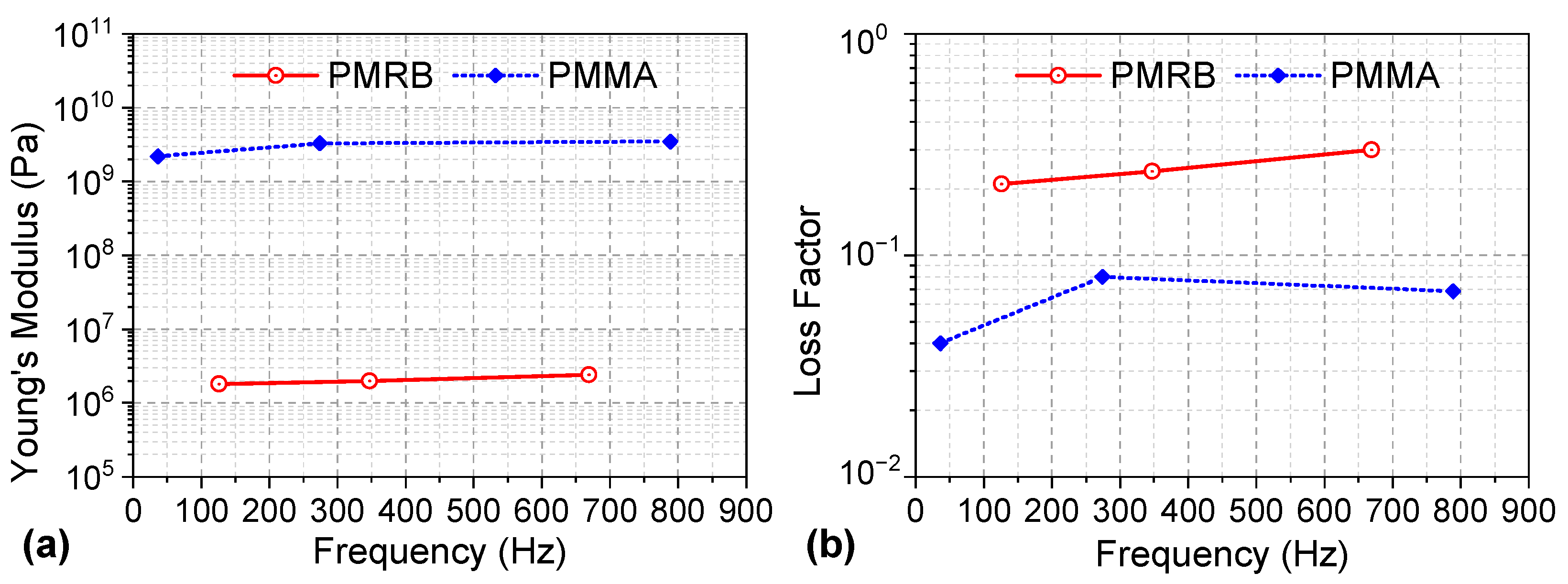
3, respectively. The Young’s modulus and the loss factor of the aluminum were set as 77.6 GPa and 0.001, respectively, while those of the PMRB and PMMA were tested in an experiment, as shown in
Figure 13.
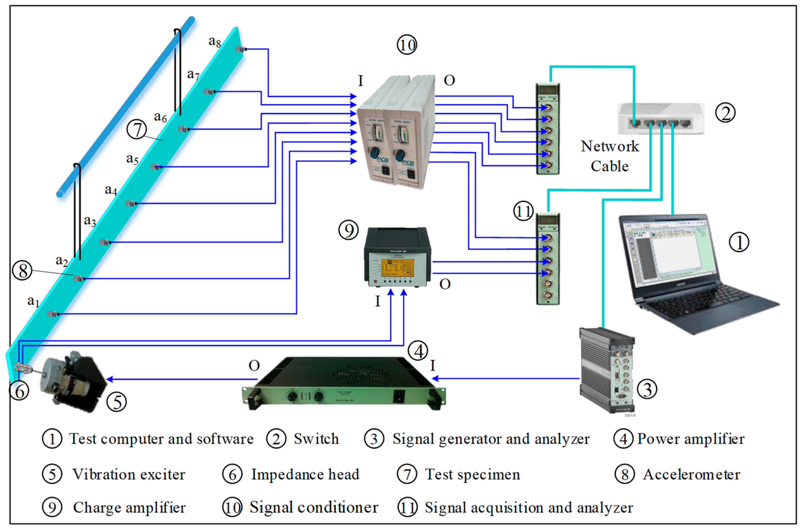
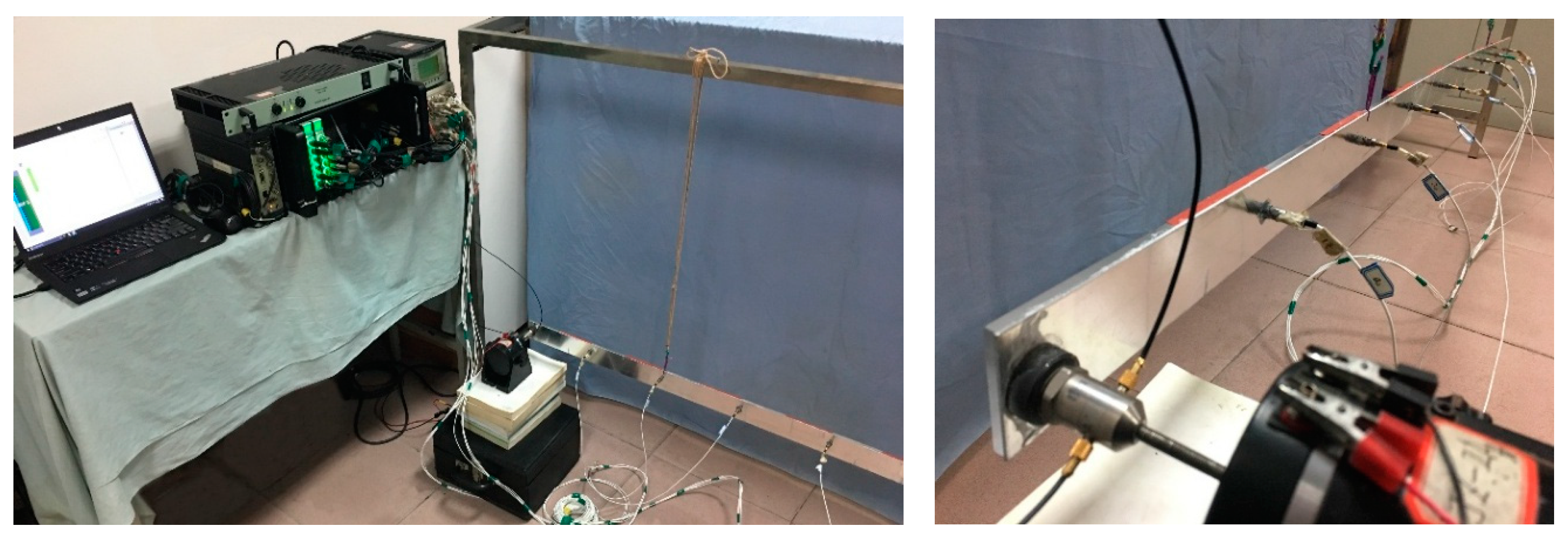
The experimental schematic diagram and the practical experimental setup are shown in
Figure 14 and
Figure 15, respectively. The specimen was suspended by two elastic ropes. The signal generator and analyzer (B&K 3560B) generated an excitation signal, which was transmitted to a vibration exciter (JZ 2A) through a power amplifier (B&K 2716). In order to obtain the normalized vibration response and then compare it to the analytical model, the input acceleration and input force signals were acquired using an impedance head (B&K 8001), which was mounted on the exciter. These two signals were analyzed using a signal analyzer (B&K 3050A) after the corresponding charge signals were amplified and transformed to voltage signals by a charger amplifier (B&K 2692). The input force was used as a reference signal during the post-data analysis. The excitation position was located at the left beam end to better study the vibration transmission performance. The vibration responses of the specimen were acquired using eight acceleration sensors (PCB M353B16), with each of the two neighboring sensors’ spaces set at approximately 20 cm. These acceleration signals were first transmitted to the signal conditioners (PCB 482A22) and then to the signal analyzers (B&K 3050A). The experimental data were finally processed by the testing software in the testing computer.
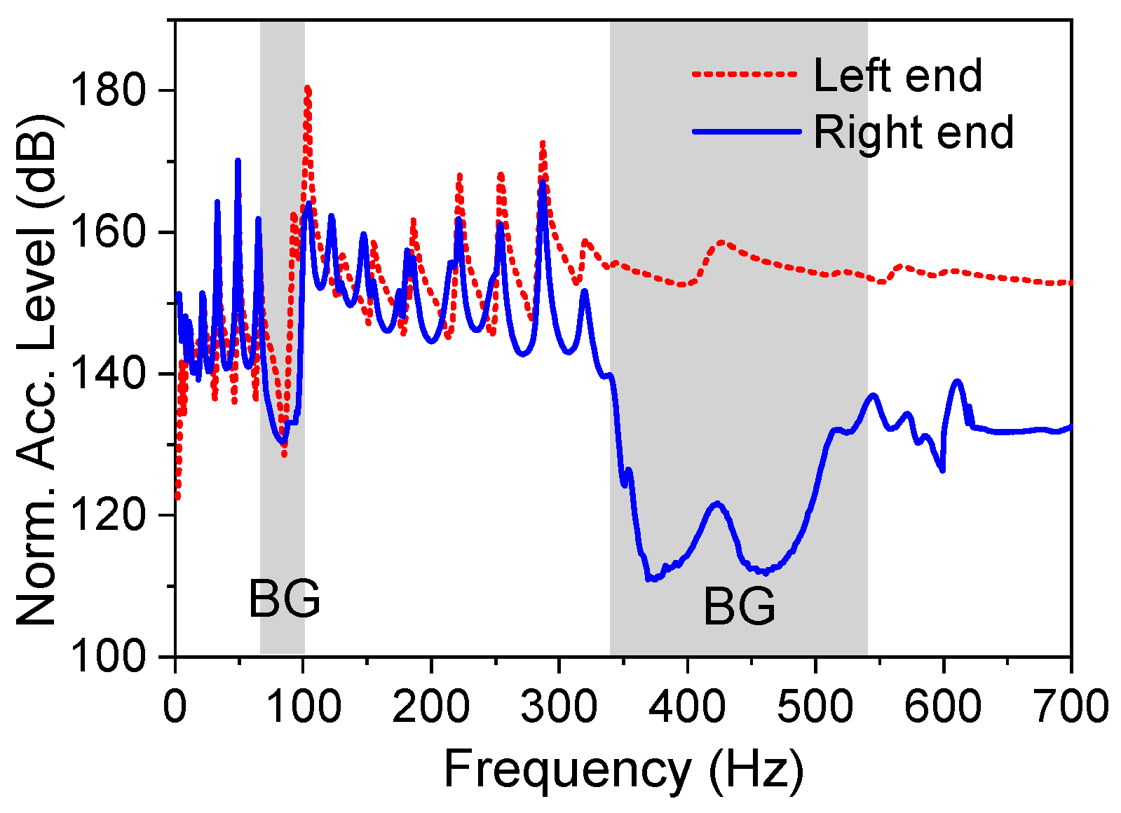
The acceleration acquired from each accelerometer was normalized by the input force. The normalized accelerations at the excitation end and at the opposite end of the specimen are given in
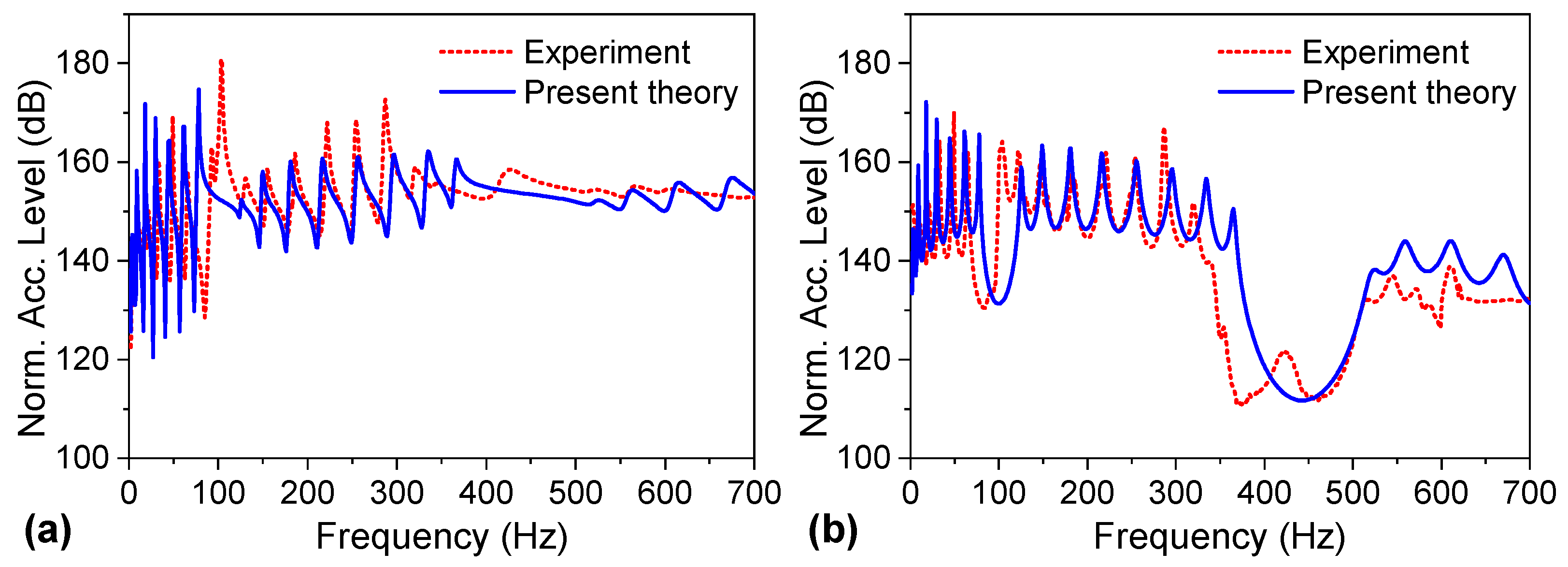
Figure 16. As shown in the figure, in the frequency ranges of approximately 65–103 Hz and 340–540 Hz, the periodic bi-layer beam provided band-gap attenuation performances where vibrations were significantly compressed for the tail end. The normalized accelerations from the experiment and the present theory are further compared in
Figure 17. As shown in the figure, the experimental results’ levels and varying trends matched well with the theoretical results in the overall frequency range, except for some specific frequencies, which validated the effectiveness of the theory. The band-gap frequency results calculated from the present theory were slightly larger than those obtained from the experiment. The differences may have been induced by the specimen’s glue between the base and free layers, which was not considered in the theoretical model.
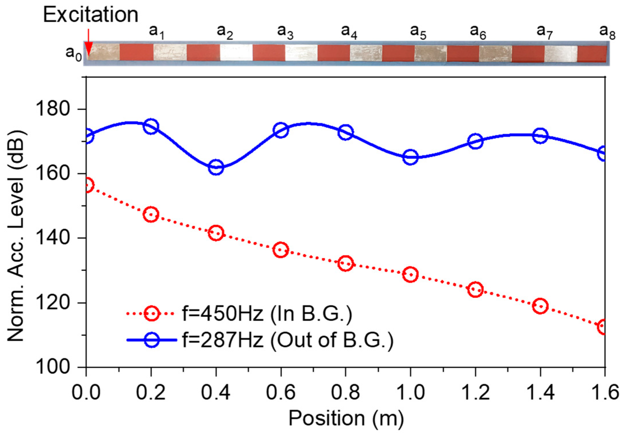
The vibration responses tested by the other acceleration sensors are also given in
Figure 18, where the transmission characteristics along the axial direction at two specific frequencies were further studied. As shown in the figure, for the frequency 450 Hz, located in the band gap, the vibrations were significantly attenuated along the direction of the wave propagation, with a decay rate of approximately 27.5 dB/m. This attenuation was caused by both the Bragg scattering and the damping. For the frequency 287 Hz, located out of the band gap, the vibrations along the axial direction performed as fluctuations, with the envelope’s magnitude decreasing with the direction of the wave propagation. This attenuation was mainly caused by the damping.
In order to further illustrate the attenuation performance of the periodic bi-layer beam, the other three specimens shown in
Figure 19 (specimens
#2,
#3, and
#4) were also fabricated and tested for comparison purposes. Specimen
#1 was the already considered periodic bi-layer beam. Specimens
#2 and
#3 were uniform bi-layer beams, with the free layers made of purely PMMA and polymer rubber, respectively. Specimen
#4 was a single-layer aluminum-made uniform beam of the same weight as the periodic bi-layer beam.
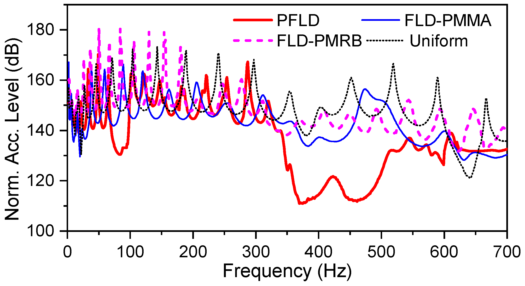
The comparison results are shown in
Figure 20. As shown in the figure, the vibration responses of the four tested specimens were comparable in the low-frequency range. In the high-frequency range, the vibrations of specimens
#1,
#2, and
#3 were lower than those of specimen
#4 owing to the damping dissipation effects.
It may seem unreasonable that the vibrations in the FLD-PMRB case were larger than those of the uniform case. One of the main reasons may be stated as follows: the uniform case’s aluminum beam thickness was set at approximately 3.8 mm, which was larger than the FLD-PMRB case’s base layer thickness of 1.85 mm, resulting in the uniform case’s bending rigidity being potentially larger than that of the FLD-PMRB case. In addition, the Young’s modulus of the damping layer in the FLD-PMRB case was very small (approximately 0.002 GPa), which was quite small compared with that of the aluminum base layer (76 GPa). In addition, at the lower frequencies, it was harder to dissipate energy through the free layer’s damping because of the large wavelength. Therefore, the vibrations of the FLD-PMRB case were potentially larger than those of the uniform case at the lower frequencies. As shown in
Figure 20, with the increases in frequency, the damping dissipation ability gradually increased, and the FLD-PMRB case’s response became smaller than that of the uniform case by approximately 200 Hz.
As shown in
Figure 20, in the band-gap frequency range, the vibrations of the periodic bi-layer beam were significantly reduced compared with those of the other three specimens, with an average attenuation of approximately 20 dB. Thus, the PFLD treatment was beneficial for improving the attenuation performance of the beam structure.
5. Conclusions
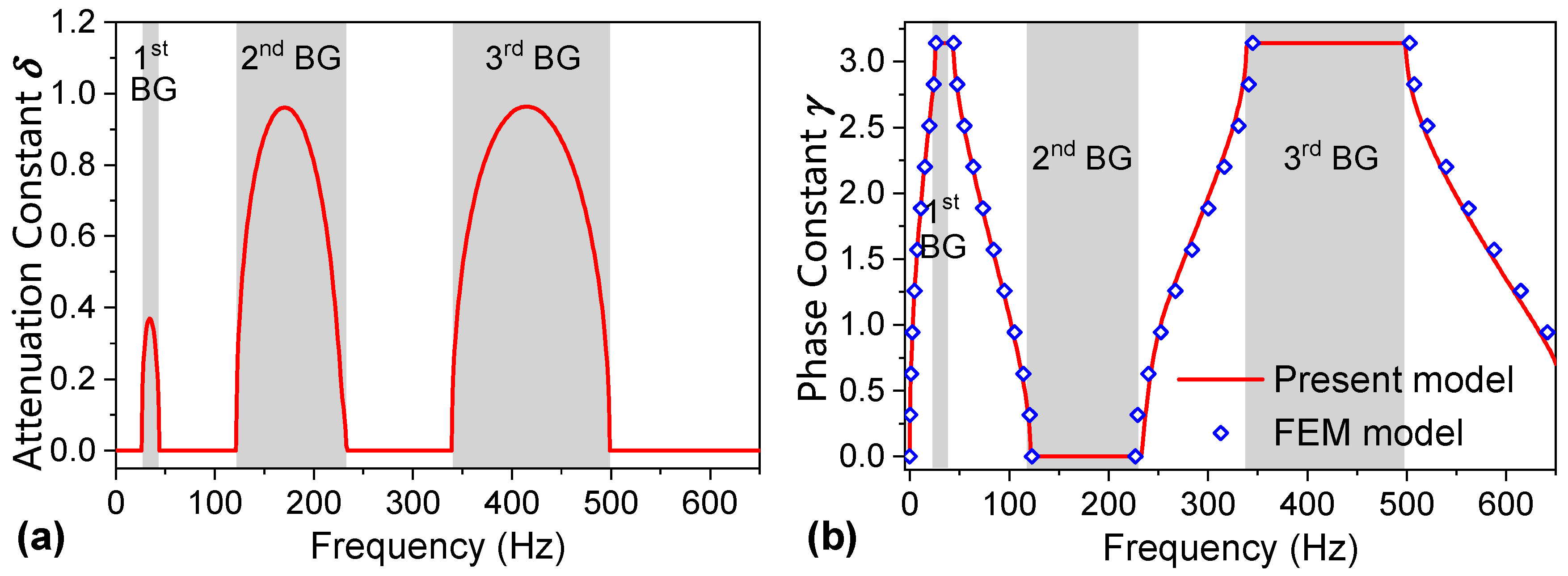
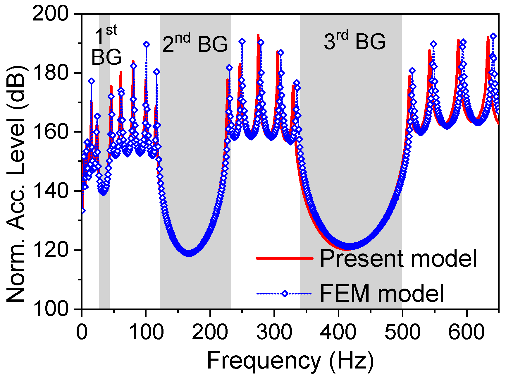
Periodicity was introduced into a damping treatment to improve vibration reduction performance, and the concept of a periodic free-layer damping (PFLD) treatment was proposed in this study. The theoretical models of the periodic bi-layer beam’s band structure and the forced response were established using the Hamilton principle and transfer matrix method. The accuracy of the theoretical model was verified by the finite-element method, showing that the analytical results matched well with the numerical simulation results.
When a viscoelastic damping material was used in a free layer of the periodic bi-layer composite beam, the flexural wave attenuation of the structure was mainly caused by the Bragg scattering effect, and the energy dissipation effect was caused by the damping. Bragg scattering played a dominant role in the band gaps, and energy dissipation played a dominant role outside the band gaps. The combined effect of the two mechanisms enabled effective control of the propagation of the waves within and outside of the band gaps in the low-frequency range.
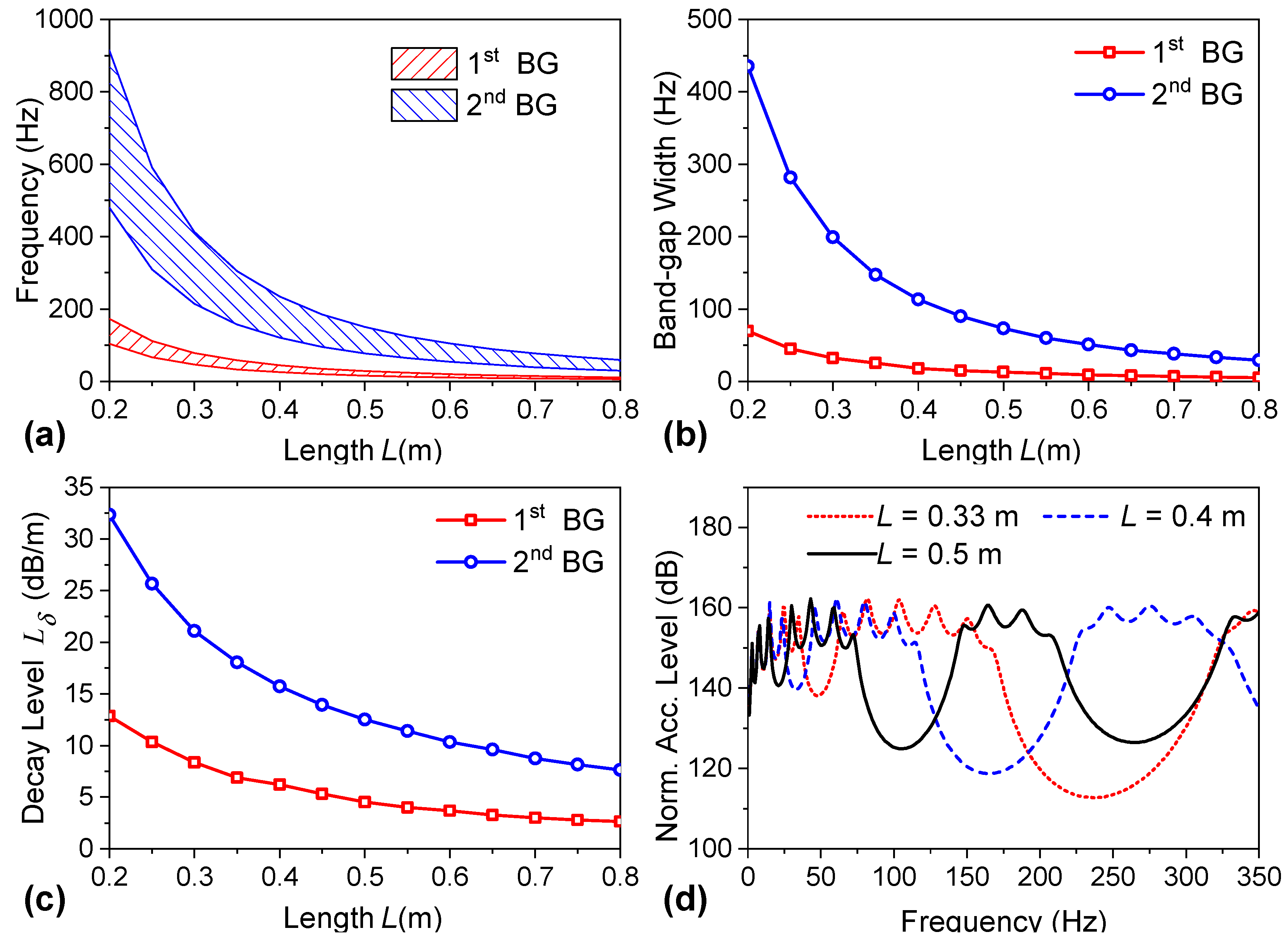
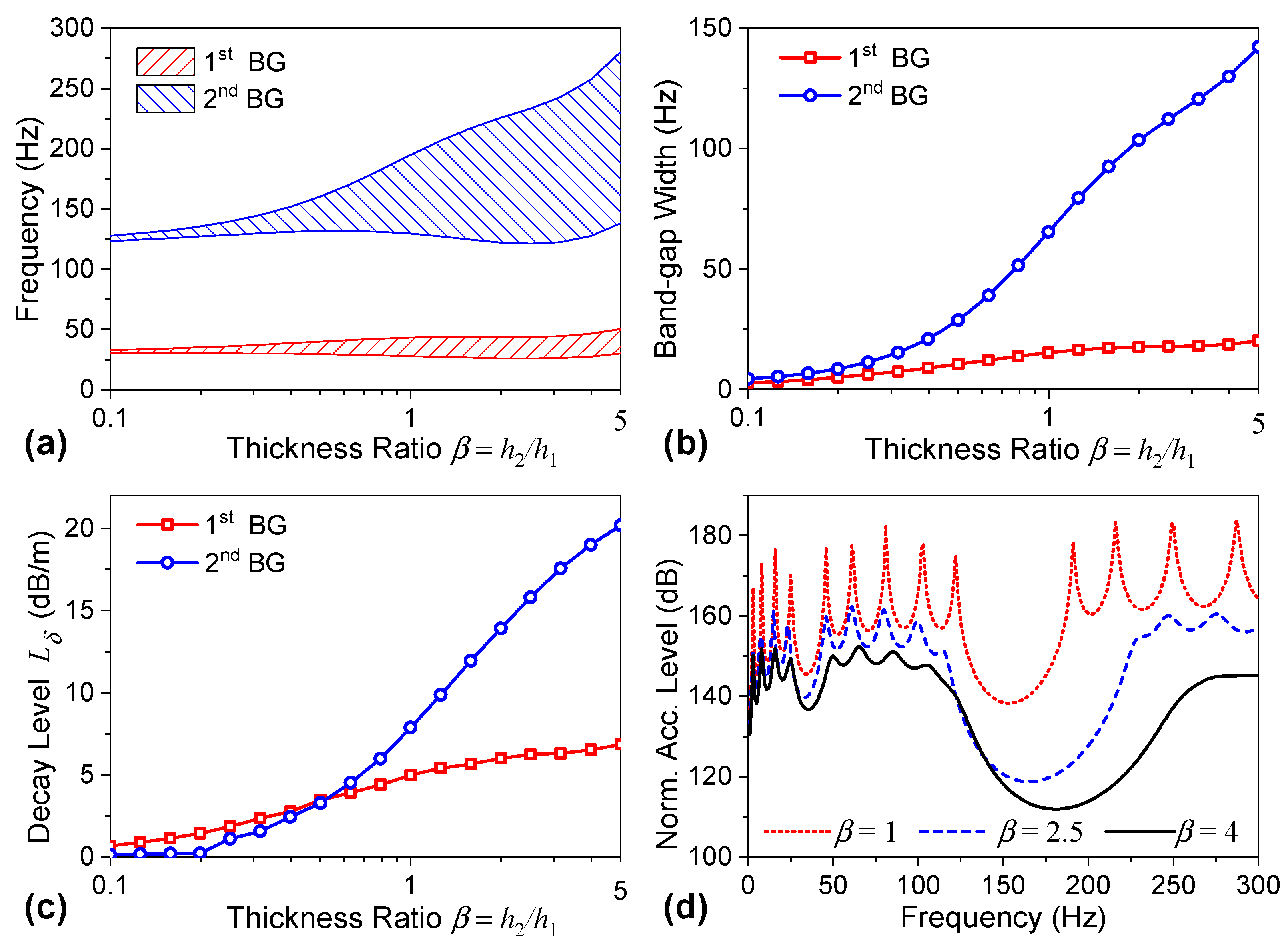
The dimensional parameters of the periodic bi-layer beam significantly affected the overall vibration reduction performance. Increasing cell lengths was beneficial for moving the band gap toward lower frequencies, but at the same time, the widths of the band gaps and the ability to suppress vibrations within the band gaps decreased. The sub-cell-length ratios should be carefully designed with moderate values to balance the effect of the Bragg scattering and the damping dissipation to achieve better performances both inside and outside of the band gaps. Under actual conditions, the greater the thickness ratio was between the free and base layers, the more favorable it was for structural vibration suppression.
The experiment results showed that the PFLD treatment can increase vibration reduction levels in the low-frequency band gaps compared with a traditional FLD treatment. This work was limited to a bi-layer beam structure with a PFLD treatment. An extension to a plate or shell structure is possible and may provide more direct guidance for controlling vibrations in practical structures.


