1. Introduction
Gravity waves are ripples in the spacetime structure predicted by Albert Einstein’s theory of general relativity, constituting a form of a matter wave [
1]. Gravitational wave detection is important for understanding the evolution of the universe and the formation of objects such as black holes and for verifying theories, such as general relativity [
2,
3]. In the field of gravitational wave detection, the ground-based gravitational wave observatory LIGO directly detected a gravitational wave event for the first time in 2016 [
4]. However, due to the limitations of the low-frequency Earth vibration and the Earth’s curvature, the detection frequency range can only cover 10 Hz~10
4 Hz [
5,
6]. The sources in this range primarily include black hole mergers with masses ranging from tens to hundreds of times that of our Sun and binary neutron star mergers, holding significant astrophysical and cosmological importance.
However, there are sources of gravitational waves with even deeper cosmic and astronomical significance, such as supermassive black holes with masses ranging from thousands to millions of times that of our Sun. These sources emit gravitational waves in the low- to mid-frequency range (0.1 mHz to 1 Hz) [
1,
2]. In order to obtain gravitational wave sources with higher red-shifts, larger scales at low and intermediate frequencies, as well as gravitational wave measurement information of deeper cosmological and astronomical significance, space-based gravitational wave detection has become a more preferable option [
7,
8].
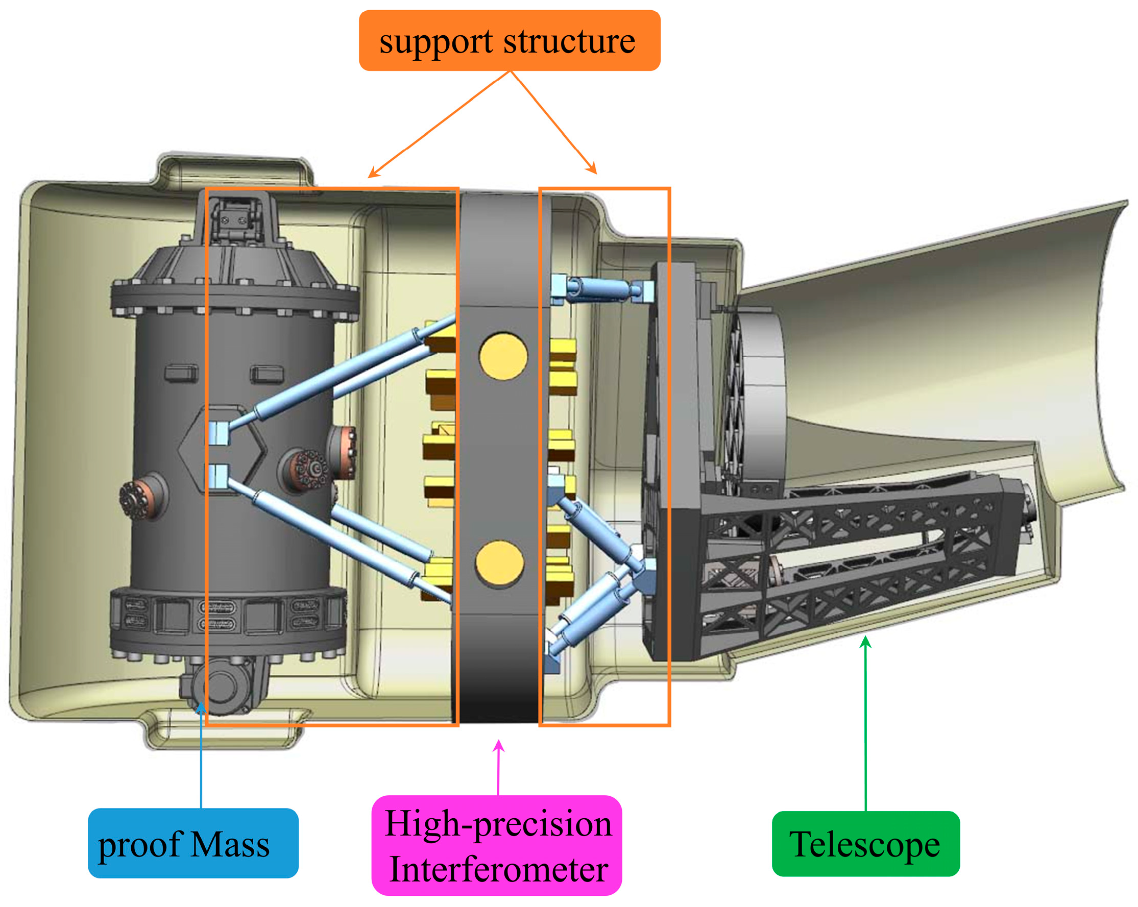
Against this background, the Chinese space-based gravitational wave detection project, the Taiji Program, was born. Its basic principle is to use a Michelson interferometer to measure the changes in the laser path caused by the stretching or compression of spacetime in the vicinity of the gravitational wave passages by means of heterodyne interferometry [
9,
10]. A Michelson interferometer is an optical device that splits and recombines light beams to measure small displacements and wavelengths through interference patterns. The basic in-satellite structure is shown in
Figure 1, and it consists of a proof mass, an interferometer, a telescope, and its support structure [
11]. The satellite’s internal structures are used in pairs. The laser from the interferometer on the remote spacecraft passes through the telescope, and after 3 million kilometers, it will be accepted by the telescope on the other spacecraft to reach the local interferometer to interfere with the laser reflected back to the interferometer by the local proof mass [
3,
11]. However, temperature variations (about ±0.1 K) in the space environment cause small deformations in the support structure, which in turn lead to small changes in the optical path. Because the gravitational wave signal is very weak, even very small variations in the optical path can overwhelm the measurement signal [
12]. In order to achieve the goal of the Taiji Program, i.e., an interstellar ranging accuracy of 5–8 pm/Hz
1/2 [
12,
13], it is necessary that “the support system between the payloads has a thermal stability on the order of pm to ensure the stability of the measured optical path”.
However, the internal support structure of the Taiji Program is different from the traditional optical support structure. Firstly, it demands higher thermal stability (pm level), making traditional support materials like aluminum alloys and titanium alloys with relatively large coefficients of thermal expansion (CTEs) unable to meet the thermal stability requirements of the Taiji Program. For instance, the CTE of titanium alloy is approximately (8.6~10.03) × 10
−6/K, while aluminum alloy has a CTE in the range of (18~24) × 10
−6/K. Secondly, because the detection of gravitational waves in space is based on the detection between satellites, it requires the satellite platform to have as little as possible or even no magnetic moment to minimize the impact on the satellite attitude control [
14,
15]. Therefore, some materials with large magnetic moments, such as invar, cannot be applied to the support structure either. In addition, although carbon fiber-reinforced plastic (CFRP) can be used to obtain an ideal CTE for the support rod by adjusting the layup of the carbon fiber material [
16], due to the outgassing phenomenon of carbon fiber fabric (which is the release of gases absorbed or trapped, such as water vapor, during the CFRP production process), it can potentially have a significant impact on the dimensional stability of the structure [
17]. Finally, the support structure is not used for the connection between components but for the connection between payloads. Therefore, it is necessary to consider not only the effect of reducing the thermal deformation generated by the support structure itself but also the thermal deformation that may be generated by the connection structure between each payload. Certainly, an actively adjustable support structure is also a good choice. However, its adjustment precision is relatively low (
level) [
18], and the vibrations that motors may generate could potentially introduce noise for space-based gravitational wave detection. Therefore, it cannot be directly used in the Taiji support structure.
Although excellent results have been achieved in temperature control, the temperature change rate of the core load in Taiji-1 has realized (T ± 0.1) K/1000 s, i.e., the temperature change during the working process of 1000 s is controlled within 0.1 K, and this slow temperature change ensures the temperature in the structure can be fully conducted. At the same time, the high-precision and high-stability temperature controller inside the satellite has been able to realize the temperature control accuracy index of (T ± 0.005) K (T is the calibration temperature), i.e., the fluctuation of the temperature uniformity inside the experimental box does not exceed ±0.005 K [
19]. Therefore, it can be basically considered that a uniformly varying temperature field has been realized inside the satellite. Thus, the design of the support structure can be carried out in accordance with the uniformly varying temperature field.
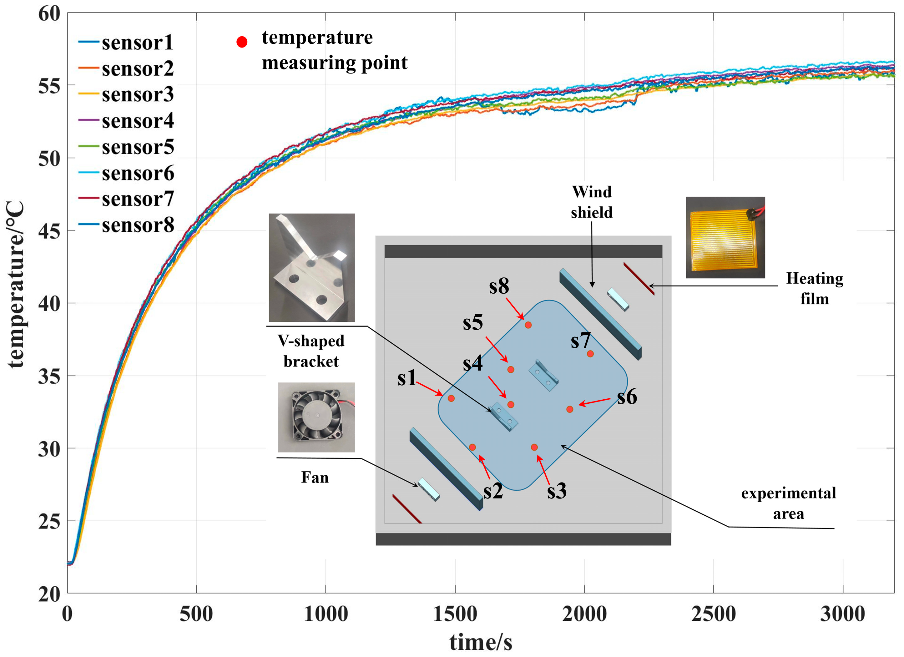
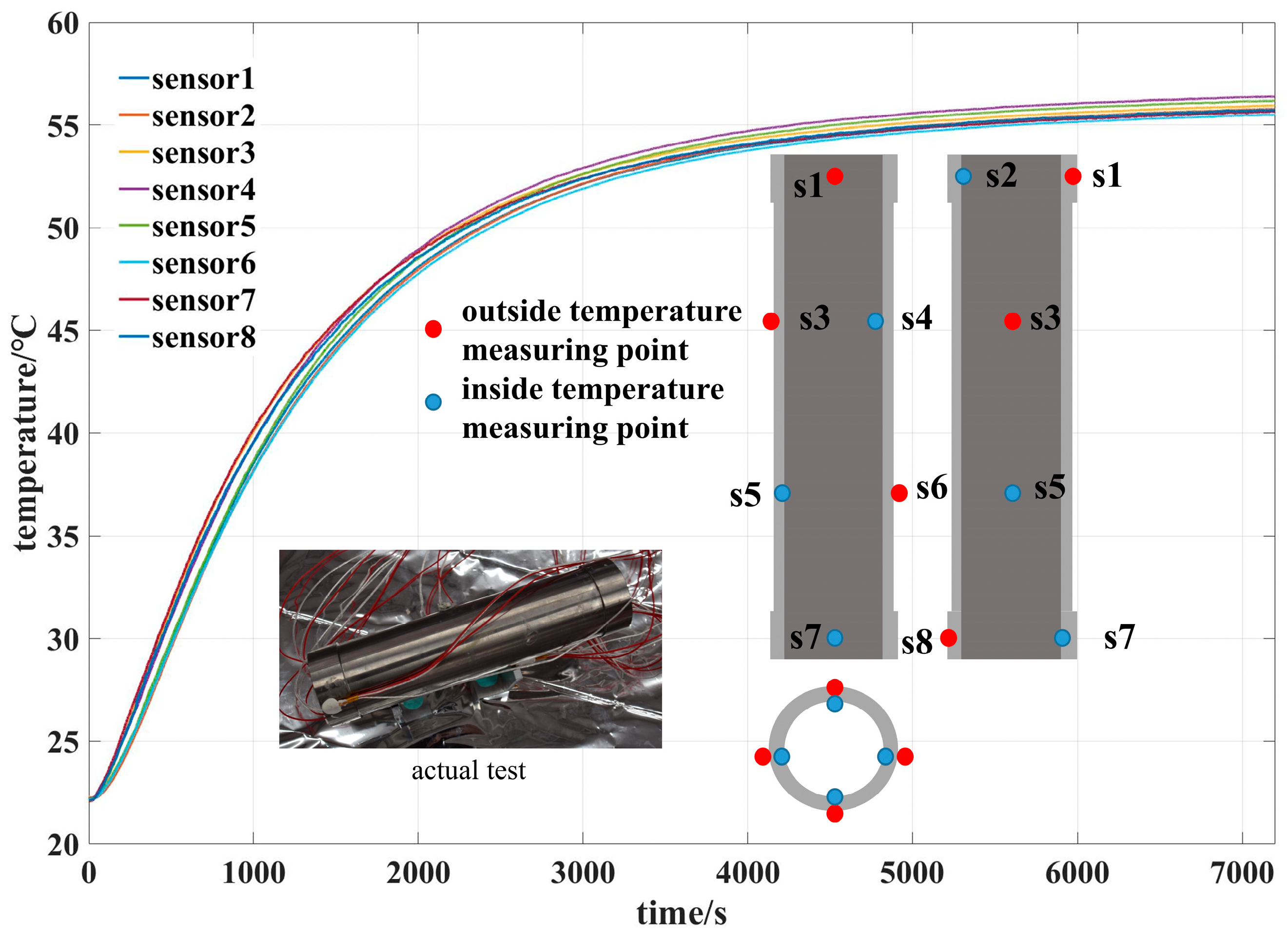
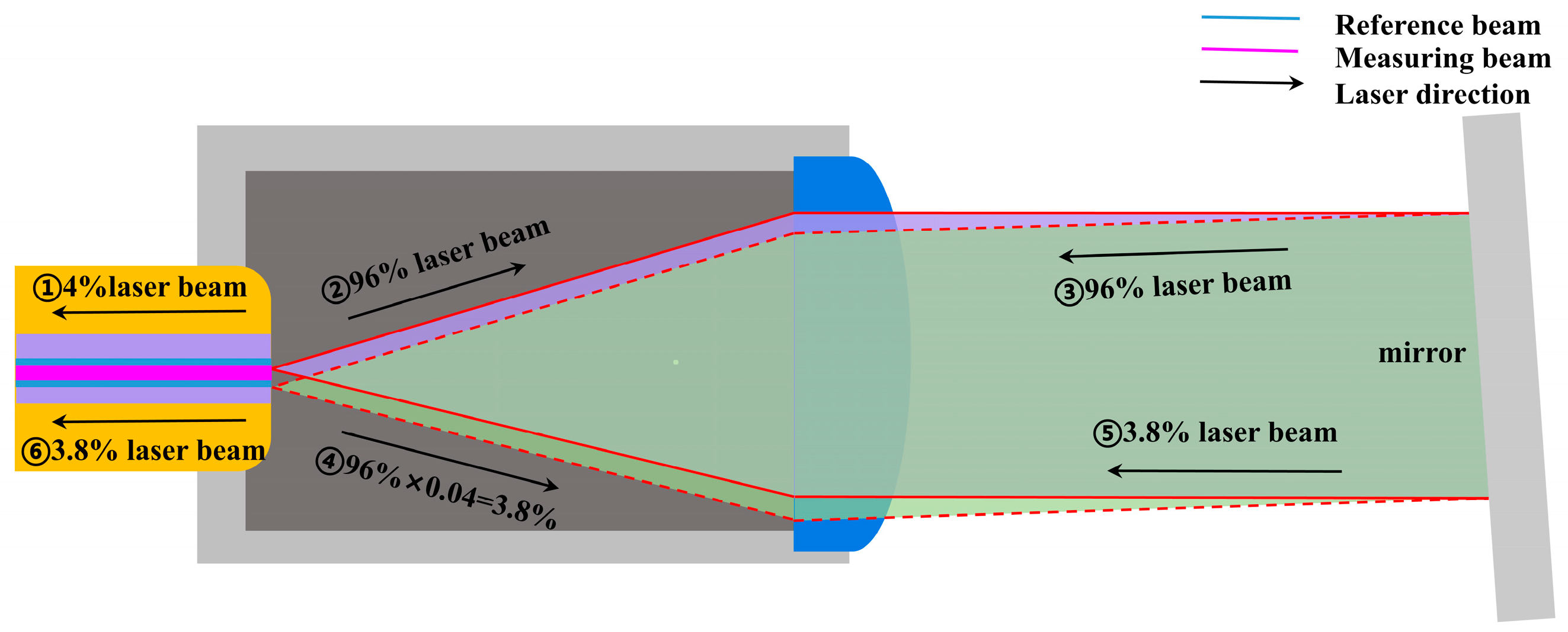
Based on the above content, in this paper, we mainly carried out three aspects of work: (1) the support structure was designed with the combination of titanium alloy and aluminum alloy, the CTE difference in each material was used to improve the overall thermal stability of the support rod, and the initial parameters of the structure were obtained; (2) the whole structure of the rod was optimized by non-linear programming by the quadratic Lagrangian hybrid algorithm (NLPQL) [
20], the CTE of the structural parameters that meet the requirements of the structural parameters was obtained, and the error caused by the change in the CTE of each material was calculated; and (3) in the ground temperature-controlled experimental box, the fiber-based interferometer and the temperature-controlled box were used to determine the thermal expansion coefficient of the support structure, and the actual overall thermal expansion coefficient of the structure was obtained. Through the above work, we hope to contribute to the successful implementation of the Taiji Program and the further development of the field of space gravitational wave detection. In the next phase, we will continue to explore the stress and strain mechanisms arising from the different CTEs of each material, aiming to further enhance the thermal stability of the support structure. Ultimately, our goal is to achieve the pm level of dimensional stability required for the Taiji Program.
2. The Design Process of the Taiji Support Structure
2.1. Specific Design Process
Although it is difficult for many single materials to meet the needs of the Taiji Program in a uniform temperature field, it is possible to use the different thermal expansion characteristics of the materials to produce a certain difference in the thermal expansion process. Meanwhile, by adjusting the length of the rod of different materials to obtain the specific difference in thermal expansion, this changes the CTE of the entire rod. At the same time, the slow temperature change allows the metal to conduct heat sufficiently so that the different materials reach the same temperature. According to Equation (1) for thermal expansion,
is the displacement change, is the material length, is the temperature change, and is the CTE of the material.
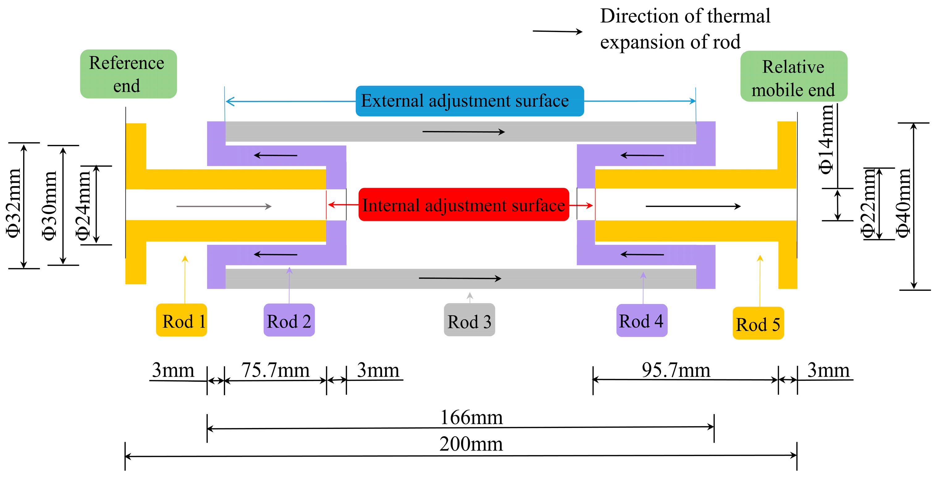
We designed the thermal expansion support rod as shown in
Figure 2. One end of the rod is the reference end, and another rod of a different material, from the other end of the previous rod, is expanded in the opposite direction to counteract the thermal deformation of the previous rod. According to the difference in the thermal deformation of the different rods, the displacement of the whole rod relative to the moving end and the reference end can be controlled. Therefore, it is possible to realize an arbitrary CTE between the reference end and the relative moving end of the whole rod within a certain interval, and the CTE of the whole rod can be adjusted by adjusting the length of the sub-rod (i.e., the distance between the adjustment surfaces) within a certain range of the amount of adjustment.
The design is a tube-like rod structure; due to the uniform temperature field, in order to facilitate the calculation, it will be made into a symmetrical design, that is, rod 1 and rod 5 and rod 2 and rod 4 are of the same length and material. Assuming that
is the CTE of rods 1, 2, 3, 4, and 5, one obtains
,
. Based on the geometric relationship, the following equation can be obtained:
is the displacement change for the linear thermal expansion of the overall rod; is the displacement change for the linear thermal expansion of rod 1, rod 2, rod 3, rod 4, and rod 5, respectively; and is the length of rod 1, rod 2, rod 3, rod 4, and rod 5, respectively.
According to Equations (1)–(3), it can be seen that the larger the difference between the CTE of rod 2
and the sum of the CTE of rods 1 and 3
, the larger the difference in the lengths of the sub-rods and the larger the space of the design. At the same time, according to Equations (2), (4), and (5), it can be seen that if the support rod is to realize a negative coefficient of expansion, it has to satisfy
. The CTE of the whole rod
can also be obtained as
By choosing a material with a large difference in the CTE, i.e., satisfying
and, at the same time, taking into account the low or no magnetic moment and light weight, the aluminum alloy 7A09 and the titanium alloy TC4 are used as the support rod materials, i.e.,
,
. The connection structures at both ends of the support structure will undergo a displacement of
for a temperature change of 0.1 K. Additionally, given the distance between these two connection structures of 200 mm, it is required for the overall CTE of the entire rod to be
to compensate for this displacement when conducting the validation design for a support distance of 200 mm. A negative CTE means that when the temperature increases, the volume or length of the object shrinks. This means that many displacements caused by metal or other positive CTE materials due to temperature changes can be offset in the application of spatial support structures. According to the material properties of aluminum alloy 7A09 and titanium alloy TC4 provided by the materials’ manufacturer, which are shown in
Table 1, Equations (3)–(6) can be calculated to obtain the initial design values of each rod, which are
,
, and
.
By inserting them into Equation (6), it can be concluded that the CTE of the whole rod should be .
2.2. Optimization of the Structure and Error Analysis
In the actual working condition of the support rod, the temperature change should satisfy (T ± 0.1)K/1000 s. However, in the actual simulation process, the displacement change under the temperature difference is too small, which makes the simulation result unreliable due to the computer calculation error. In order to avoid this problem, in the actual simulation process, the amount of the temperature change will be increased, so that the displacement caused by thermal deformation increases, and then the result will be divided by the corresponding temperature rise times to obtain the actual approximate results. Therefore, in the simulation, the temperature field is set to a uniform temperature field with a temperature rise of
, i.e., the temperature change range is 20 °C~40 °C. According to the material properties of 7A09 and TC4 shown in
Table 1, and the corresponding temperature change, the corresponding finite element model is established for calculation. Its grid model is shown in
Figure 3. The minimum length of the elements in the model is 0.36486 mm, the maximum length is 1.13 mm, the minimum Jacobin is 0.72, and the maximum aspect ratio is 2.92. At the same time, the number of elements is 195,840. Due to the fact that the structure is inside a temperature-controlled box within the satellite, where the temperature changes very slowly and the thermal conduction within the structure is significant, we assume that the temperature is uniform across all nodes and the initial temperature is 20 °C. We directly apply the uniformly varying temperature field (20~40 °C) to all the nodes of the finite element model. Because the satellite experiences minimal gravitation in space, which can be almost entirely neglected, the structure is essentially free from any external payloads. Additionally, the pressure inside the temperature-controlled box has little to no impact on the structure. Therefore, we do not apply any forces or pressure within the model. And the thermal conduction at the contact surfaces of the structural components is also direct conduction. And one end of the rod is limited to only one degree of freedom of the axial displacement. The simulation solution is carried out by using the OptiStruct of HyperMesh in hyperworks.
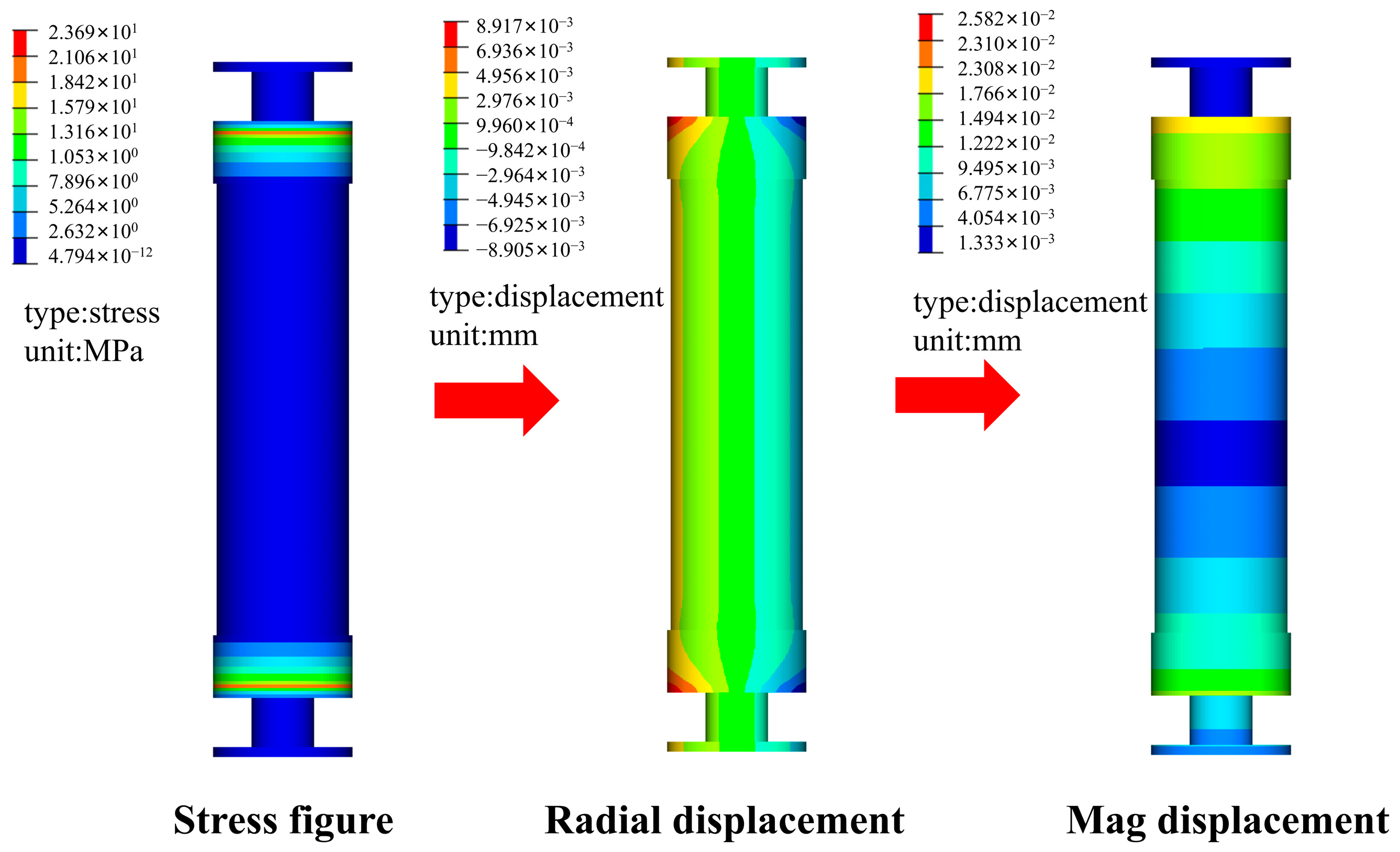
However, due to the different CTEs of titanium alloy and aluminum alloy, a certain amount of stress will be generated, which will lead to a certain amount of strain in the rod, which will in turn affect the displacement accuracy of the whole rod. As shown in
Figure 4, if the initial value of the above equation is directly adopted, the relative displacement of the two ends is
mm. According to Equation (1), the CTE of the whole rod can be obtained as
, which is 34.06% different from the theoretical data.
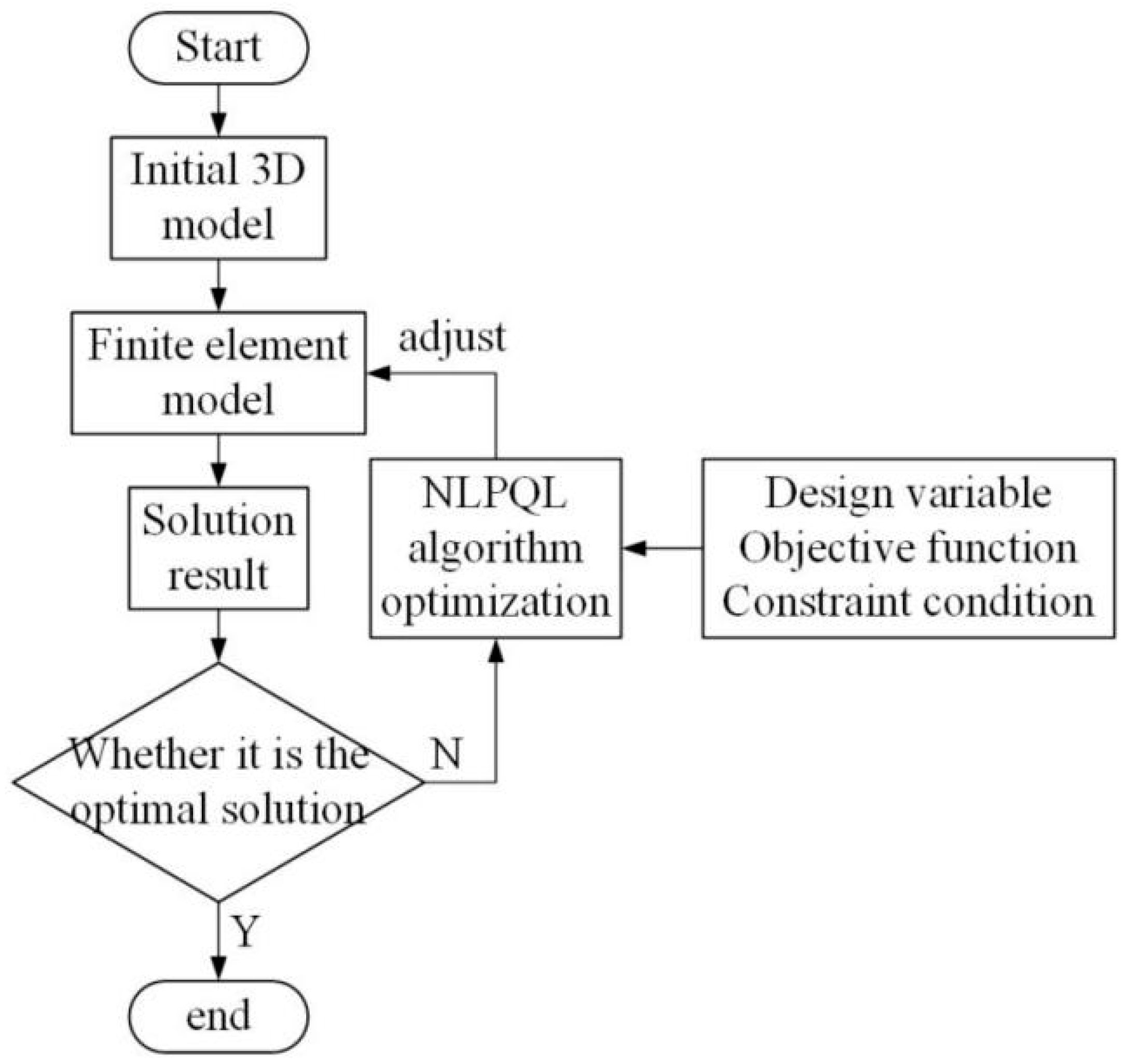
In order to achieve the desired accuracy, we optimize the structure by using the optimization method of the NLPQL with the objective of the CTE as
, i.e., the relative displacement of the two ends reaches
for optimization. The optimization process is shown in
Figure 5.
Assuming that the distance between the internal and external adjustment surfaces is the design variable , the final optimized result is .
Due to the precision of processing, after rounding off the length of each rod, the final results are , , and . Its final thermal deformation is −0.004032286 mm, and the CTE is .
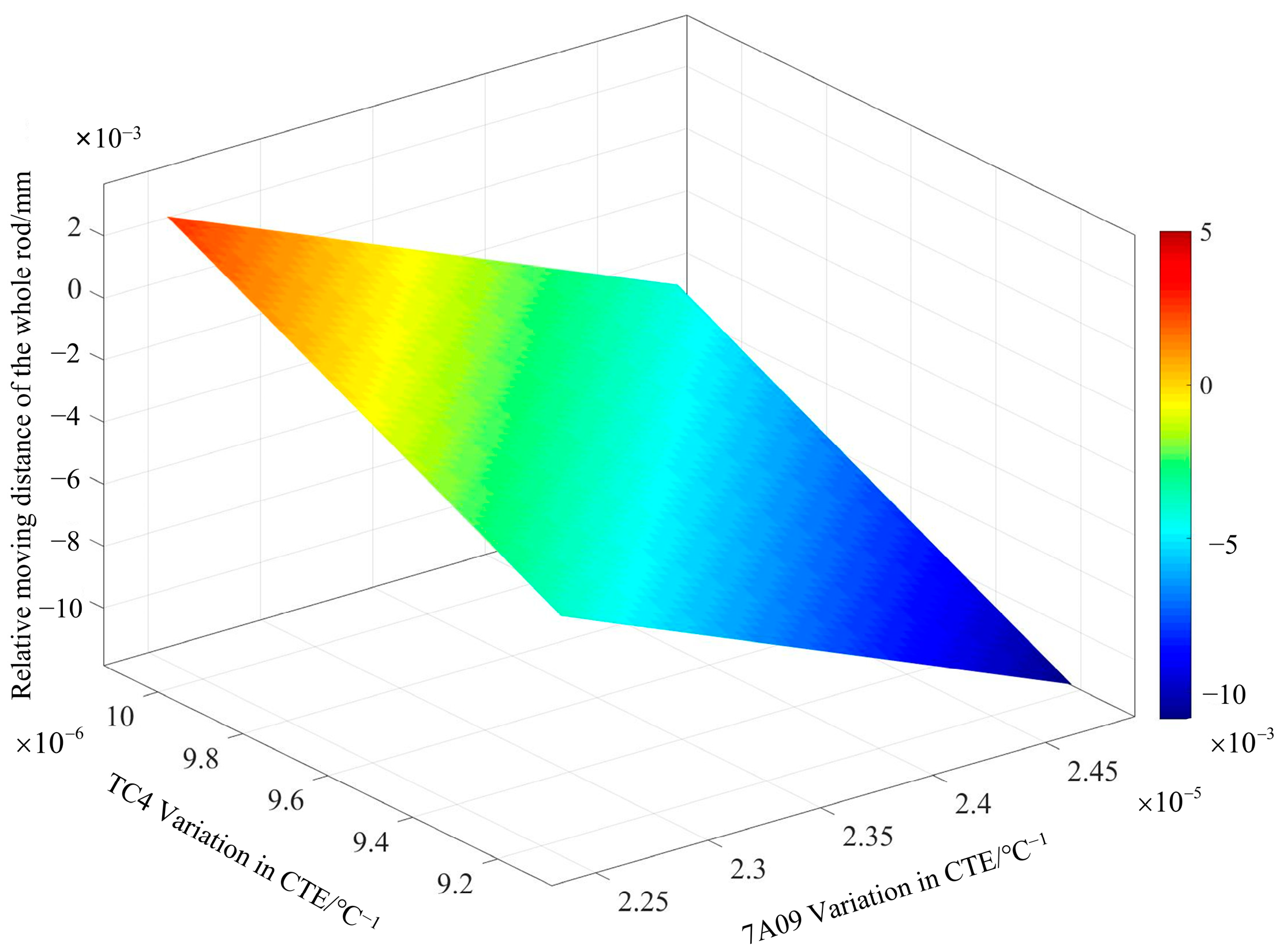
Because there may be some errors in the measurement data of the CTE of the material due to the measuring instruments in the actual measurement process, the DOE full factorial design method [
21] is utilized to sample the possible errors. We take the CTE of two materials within the range of ±5%, with 1% as a sampling interval. The results of the response surface are shown in
Figure 6. In the temperature difference in a 20-degree range, the displacement of the two ends of the whole rod and the relative change in the CTE of the two materials have a certain proportionality, that is, the CTEs of the two materials at the same time increase or decrease; a certain percentage of the thermal deformation of the whole rod displacement change is relatively small, while the two materials produce a relative change in the thermal deformation of the whole rod which will produce a huge change in the displacement of the thermal deformation of the whole rod. The figure confirms Equation (6), that is, the influence of the thermal expansion coefficient of each rod on the whole rod.
4. Conclusions
In the Chinese Taiji Program, the support structure between the payloads requires high thermal stability and low or no magnetic moments. In order to meet these requirements, a support rod with a CTE of was designed by using titanium alloy and aluminum alloy, and the optimized CTE was . The CTE of was verified by the experiments, which is 9.5% different from the simulation results, and the feasibility of this design was verified. This result essentially meets the Taiji Program’s requirement for a whole 200 mm support rod with a CTE of .
Next, we will delve deeper into the stress and strain mechanisms resulting from the different CTEs of each material, aiming to further enhance the thermal stability of the support structure. Following this, the final support structure will be integrated into a satellite for comprehensive testing, validating its thermal and dimensional stability within a real-world environment.
In conclusion, this study provides a useful exploration and theoretical basis for the design and optimization of the support rods in the gravitational wave detection project of the Taiji Program, which provides strong support for the successful implementation of the project. In the future, we will further improve the material properties and optimize the structural design to achieve higher precision and stability for the support rod so as to contribute to the field of gravitational wave detection.
