Abstract
Tooth surface wear causes variation in meshing stiffness and transmission error of the gear system and further causes the fluctuation of dynamic characteristics. In this study, a dynamic behavior prediction model of the gear transmission system was established, which considered the machined tooth surface wear based on the mixed lubrication sliding wear model and the gear tribology-dynamic model. The gear pair wear characteristics along the meshing line were analyzed through simulations, and the impacts of wear conditions, operating torque, and speed on the dynamic characteristics of the gear transmission system with tooth surface wear were discussed. The results demonstrated that the transmission error and the vibration displacement amplitude of the gear system had increased gradually with the increase of the wear degree and that the fluctuation intensified. The fluctuation of gear dynamic characteristics increased with the increase in torque, and the fluctuation of gear dynamic characteristics initially increases and then decreases with the increase in rotating speed.
1. Introduction
The helicopter transmission system consists of multiple pairs of gear drives. During long-term operation, gear wear becomes unavoidable and gradually increases [1,2]. The wear would cause the uneven removal of the metallic material on the tooth surface, leading to the reduced efficiency and accuracy of the gear transmission [3,4]. At the same time, wear would also result in incidental noise and vibration in the gear transmission system, thereby causing a dynamic load of the gear teeth to increase sharply and harm the overall mechanical performance of the instrument, and even cause serious mechanical accidents [5,6,7,8]. A comprehensive understanding of the impact of wear in gear transmission during gear operation is significant for gear optimization design.
Monitoring the wear status of gear transmission systems through dynamic response characteristics is important for improving transmission accuracy and extending the life of equipment [9,10,11]. To address the effect of gear wear on dynamic behavior, Ding et al. [12] proposed a spur gear wear characteristic model based on Archard’s wear model and analyzed the effect of spur gear wear on dynamic meshing force and transmission error. Osman et al. [13] established a quasi-static model of spur gears and helical gears, which considers the effects of wear based on the Archard’s wear model. Yuksel et al. [14] investigated the effect of surface wear on the dynamic behavior of a typical planetary gear set based on Archard’s wear equation. The main approach to modeling the correlation between wear characteristics and dynamic behavior is to consider tooth wear into the gear mesh stiffness and transmission error excitation. Wang et al. [15] analyzed the effect of tooth surface wear on the time-varying mesh stiffness (TVMS) based on Archard’s wear and Weber-Banaschek model. Shen et al. [16] integrated Archard’s wear into the dynamic model using TVMS, no-load static transmission error (STE) along with gear backlash and the vibration response of planetary gears is analyzed. Zhang et al. [17] comprehensively considered the gear nonlinear dynamic model and the Archard’s wear model, and the effect of wear on the nonlinear behavior was discussed. This was based on the fact that the Archard’s wear model takes little account of the lubrication and tooth surface morphology. In fact, gears usually work in a lubricated state [18,19,20]. The tooth surface morphology, lubricant flow and rough peak contact make the tooth surface contact state significantly different from that of dry contact when the gear is lubricated. The complex contact state between tooth surfaces has a great influence on the tribological and dynamic characteristics of gears. Presently, there are no sufficient studies on wear characteristics and dynamic behavior prediction of gear tooth surfaces under lubrication conditions.
In this study, a mixed-lubrication sliding wear model which considered the microtopogrphy of the gear tooth surface was established, and the wear characteristics of the key points in the mixed-lubrication contact were studied by taking the grinding tooth surface machining as an example. The calculation methods of the time-varying mesh stiffness and the static transmission error of the gear teeth after wear were deduced, and the variation of dynamic meshing force and the dynamic transmission error of the gear system is investigated. The effects of wear form, torque, and speed on gear dynamics, are discussed. This paper aims to lay a technical foundation for gear wear fault monitoring and diagnosis.
2. Theoretical Background
2.1. Gear System Dynamic Model
Figure 1 depicts the tribological-dynamic model of the involute gear. Furthermore, the cartesian coordinate system is built in the direction depicted in the figure, and the y direction represents the direction of the gear meshing line. Each gear has translational freedom along x and y and torsional freedom θ around the axis. The subscripts p and g in the figure represent the pinion and the gear, respectively, and the pinion gear refers to the driving gear.
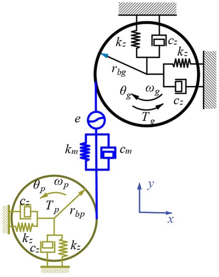
Figure 1.
Tribological-dynamic model.
The gear dynamic transmission error (DTE) is:
where e stands for the static transmission error.
The sum of elastic meshing force and viscous meshing force is known as dynamic meshing force (DMF).
According to Newton’s second law, the dynamic differential equation of the system is:
2.2. TVMS and STE Calculation Considering Wear
As shown in Figure 2, the gear teeth are simplified as a cantilever beam with a variable cross-section on the root circle.
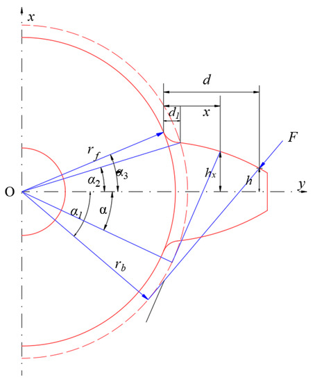
Figure 2.
Gear tooth cantilever beam model.
When the gear teeth are worn, the variation of the geometric parameters of the gear is as follows:
It is commonly assumed that tooth surface wear only affects the gear’s bending stiffness kb, radial compression stiffness ka, shear stiffness ks [21]. The meshing stiffness of a single tooth with wear is obtained by varying the gear geometric parameters as follows:
where , .
When a single tooth meshes, the TVMS is:
When double teeth mesh, the total TVMS is:
The STE is the key internal excitation of gear dynamics in gear transmission. When the gear is driven at a low speed, STE can be expressed as the absolute deviation of the gear pair equivalent error and the elastic deformation of the gear teeth along the direction of the meshing line from the theoretical contact point.
Gear processing and installation will invariably result in pitch error fpt, tooth profile error ff, tooth direction error fb and center distance error fa. Wang et al. [22,23] simplify the effect of center distance error on the meshing line by assuming that the tooth profile error is perpendicular to the tooth direction error. The above four main errors of the contact tooth pair are fitted along the direction of the meshing line, and the system equivalent error caused by machining and installation can be obtained as follows:
Gear wear is the equivalent of a profile modification. The STE can be calculated by adding the elastic deformation, comprehensive error, and wear depth.
2.3. Wear Depth of Tooth Surface under Mixed Lubrication
Ren et al. [24] proposed a deterministic line contact mixed EHL model as the key to solving lubrication characteristics. In general, the Reynolds equation is used to calculate fluid dynamic pressure.
Within the rough contact area, the film thickness becomes 0, and the pressure flow term disappears. The above equation is simplified as follows [25,26]:
The local film thickness equation is:
The elastic deformation of the surfaces is [27]:
The following equations are used to calculate the relationship between fluid density-pressure and viscosity-pressure:
The contact load and the hydrodynamic pressure balance the load applied to the contact area:
It is assumed that the material removal obeys modified Archard’s law [28].
Because rough surfaces are random, a simple section wear height cannot adequately describe the surface’s wear law. In the presence of enough sample points, the average wear height can be described as follows:
The surface height matrix can be expressed as: , c is a coordinate reference constant .
Figure 3 depicts the current work’s solution process. In the current study, simulations were carried out using MATLAB software. To solve the wear depth on rough surfaces, we first obtain the film thickness and pressure on the rough surface without wear based on the stable solutions of film pressure and film thickness on the smooth surface. Then, using Archard’s wear model, calculate the wear height of each rough direct contact area, and update the surface height data. For a new iteration, the new surface is introduced into the film thickness equation. After approximately 3000 time steps of computation, the convergent solution and wear depth are obtained.
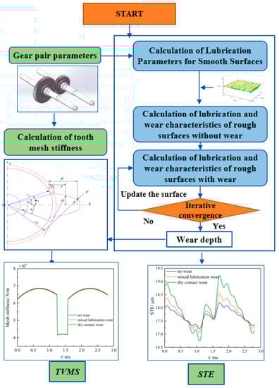
Figure 3.
Calculation of dynamic characteristics of gear system considering tooth surface wear.
3. Results and Discussion
Table 1 shows the basic parameters of the gear pair, and Table 2 lists the material parameters of the gear.

Table 1.
Basic parameters of gears.
Table 2.
Material parameters of the gear pair.
The dimensions of the stressed volume in the calculation of tooth surface wear under mixed lubrication are −3.2a ≤ x ≤ 1.8a, −2.5a ≤ y ≤ 2.5a. The lubricating oil’s initial viscosity is η0 = 0.01119 Pa·s. To accelerate the solution, the progressive mesh refinement method is used [29]. As shown in Figure 4, the rough surface is measured using a 3D non-contact topography measuring instrument (UP-Dule Mode, Rtec Instruments, San Jose, CA, USA). The main performance indicators of UP-Dule Mode are shown in Table 3.
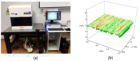
Figure 4.
Machined rough surface. (a) 3D topography measuring instrument. (b) The ground surface.
Table 3.
UP-Dule Mode performance indicators.
3.1. Dynamic Characteristics Table 3. UP-Dule Mode Performance Indicators of Gears under Dry Wear and Mixed Lubrication Wear
Before analyzing the wear characteristics of the involute spur gear, a load tooth contact analysis (LTCA) is required to determine the number of gear teeth meshed at a given point in time and the load distribution between the gears. Figure 5 depicts a simplified model of the spur gear at the meshing point. The pinion and gear center points are represented by O1 and O2. rAp and rAg are the pinion and gear’s tooth top circles, respectively; rbp and rbg are the pinion and gear’s base circles, respectively. ω1 and ω2 are the angular velocities of the pinion and gear, respectively. A and E are the approach point and recess point of the gear respectively, B and D are the junction points of the single tooth meshing zone and the double tooth meshing zone, P is the pitch point.
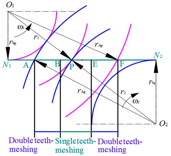
Figure 5.
Simplified model of spur gear.
This section examines the dynamic characteristics under three conditions: no wear, mixed lubrication sliding wear, and dry wear. The pinion rotates at 1000 r/min and has a torque of 300 Nm. Figure 6 depicts the variation of contact parameters during meshing. The deformation coordination condition [30] solves the load distribution of the double-tooth meshing zone.
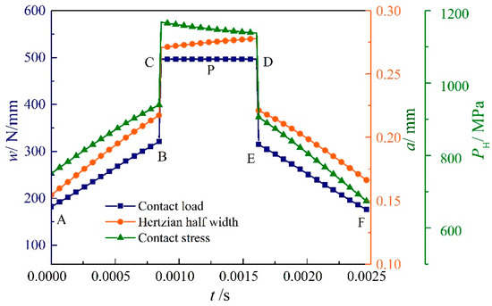
Figure 6.
Gear contact parameter distribution.
In Figure 6, the contact load, and Hertz contact stress, increase gradually from meshing starting point A to B, where the double-tooth meshing and single-tooth meshing exchange. The contact load remains constant after entering the single-tooth meshing zone, while the Hertzian contact stress gradually decreases. Therefore, the contact load and Hertzian contact stress change abruptly at the transition from single-tooth to double-tooth meshing and gradually decrease in the double-tooth meshing interval (E–F). Table 4 Shows the load and relative sliding speed at each key point.
Table 4.
The load and relative sliding speed at each key point.
The wear characteristics of the key meshing points are numerically simulated to better understand the meshing process’s wear characteristics and to aid in the analysis of the dynamic characteristics. Figure 7 depicts the wear cloud diagram and the change in accumulated wear of various meshing points.
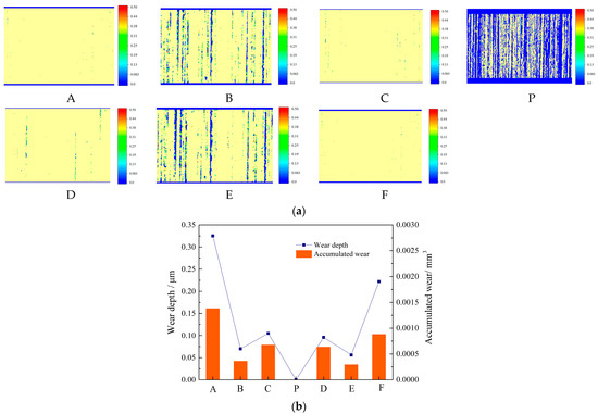
Figure 7.
Tooth surface wear distribution and wear depth. (a) Wear distribution at different meshing points. (b) Wear depth and accumulated wear.
The wear at points A and F is the most severe, as shown in Figure 7a. Although the contact load is small at these two points, their relative sliding velocities are 1.112 m/s and 1.069 m/s, respectively, which are significantly higher than the relative sliding velocities at other points, as shown in Table 3. Archard’s model predicts that wear depth is proportional to pressure and relative sliding velocity. Take, for example, two points A and B; while the contact load at point A is only 59% of the contact load at point B, the corresponding relative sliding velocity at point A is 5.79 times greater. Furthermore, because point A had a thinner film, its contact area ratio was greater than that of point B, as shown in Figure 7b. Meanwhile, despite the fact that the relative sliding speeds of B and C and d and E were close, the sudden increase in load caused an abrupt change in wear at the alternating points of both single and double teeth, resulting in a significantly greater degree of wear in the single-tooth meshing area of C and D than in the double-tooth meshing area of B and E. Because the speeds between the two contacting tooth surfaces are equal at pitch point P and the relative speed is 0, wear is minimal, which is consistent with the results obtained in the literature [13].
Based on the gear wear distribution, the gear TVMS and STE with wear is obtained, as shown in Figure 8.
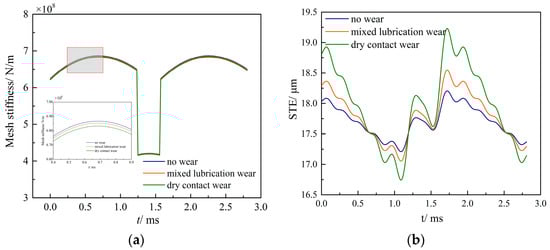
Figure 8.
Gear mesh stiffness and static transmission error. (a) TVMS. (b) STE.
The meshing stiffness has been reduced due to tooth surface wear, as shown in Figure 8a. As the degree of wear increases, the rate of reduction of meshing stiffness increases. Meanwhile, tooth wear under lubrication is less severe than dry wear because the oil film between the gear teeth prevents rough direct contact [4]. Therefore, the meshing stiffness under lubricated conditions is greater than that of dry wear. The magnitude of transmission error is increased by gear wear in Figure 8b. Because the wear is greater at the mesh start and exit points (points A and F), their STE increases significantly, as shown in the figure at 0 and 1.7 ms. The wear at the pitch point (point P) is lower, and the change in STE amplitude is also lower, as shown in the figure near 1.5 ms. The transmission error at 1 ms corresponds to points B and E in the figure. The wear is not as severe as it is at points A and F. Therefore, the magnitude of transmission error variation is not as noticeable as it is at the engagement point (0 ms). Furthermore, the wear depth of mixed lubrication sliding wear is 40–60% lower than that of dry contact wear over the same time period. Therefore, STE fluctuations under mixed lubrication conditions are not as severe as those under dry wear.
The time domain, frequency spectrum, phase, and Poincaré plots of the capstan with no wear, mixed lubrication sliding wear, and dry contact wear are shown in Figure 9.
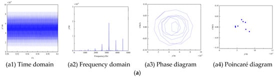
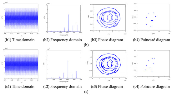
Figure 9.
Time domain, frequency domain, phase diagram, poincare diagram with tooth wear. (a) No wear. (b) Mixed lubrication sliding wear. (c) Dry contact wear.
When wear is not considered, Figure 9(a1) shows a periodic and stable change in the amplitude of displacement, whereas the amplitude fluctuation states of (b1) and (c1) gradually become irregular. Furthermore, due to the greater wear depth, the fluctuation range of dry contact wear is greater than that of mixed lubrication wear. Wear causes the appearance of a sideband near the harmonic frequency in the frequency domains of Figure 9(a2), (b2), and (c2). The traces of the phase diagrams (a3), (b3), and (c3) in Figure 9 are made up of a series of similar curves. The phase diagram’s thickness increases significantly after wear, indicating that the system is producing some fluctuations at this time. Furthermore, dry wear has a significantly thicker layer than mixed lubrication wear. The Poincaré graph gradually changes from a concentrated point to a discrete state of points, indicating that the system eventually transitions from quasi-periodic motion to chaotic motion, as shown in Figure 9(a4), (b4), and (c4). In conclusion, without considering tooth surface wear, the displacement vibration of the gear is small, and the gear dynamic characteristics are relatively stable. The vibration and noise of the system increase as the tooth surface wears, as does the system’s instability.
The time-domain and frequency-domain spectra of the DMF and DTE are illustrated in Figure 10.
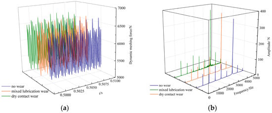
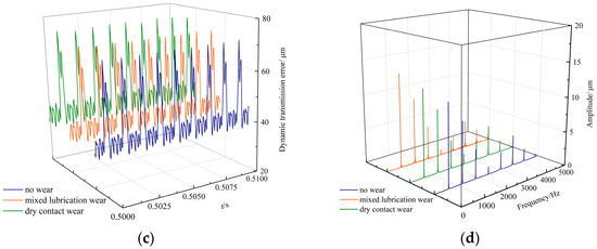
Figure 10.
Variation of the DMF and DTE. (a) DMF. (b) Frequency domain spectrum. (c) DTE. (d) Frequency domain spectrum.
As shown in Figure 10, tooth surface wear raises the average amplitude of the gear dynamic meshing force and the dynamic transmission error. The spectral structure did not change significantly, but the meshing frequency and its harmonic amplitudes changed significantly. In general, wear increases the dynamic meshing force and dynamic transmission error of the gear pair in each frequency band, with the amplitude of the system’s main frequency increasing the most. The wear depth under mixed lubrication is smaller than that under dry contact wear due to the action of the oil film, and the increasing amplitudes of the dynamic meshing force and dynamic transmission error are also smaller than those under dry wear.
To describe the dynamic characteristics at different wear conditions, Figure 11 illustrates the variation of the peak-to-peak value δp of the dynamic transmission error with the wear time for the three cases of no wear, lubricated wear, and dry wear.
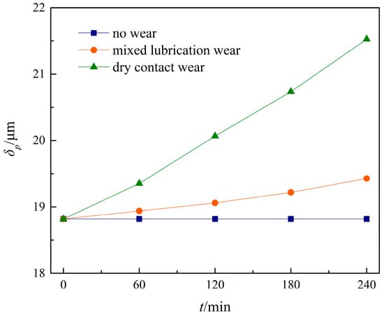
Figure 11.
Variation of the δp.
When tooth surface wear is not taken into account, δp does not change with increasing running time, as shown in Figure 11. However, if the gear is in a state of lubrication wear or dry wear, the wear will continue to accumulate as running time increases, causing δp to show an upward trend as running time increases. This phenomenon indicates that as gear running time increases, tooth surface wear will cause more severe vibration displacement and noise.
3.2. Effect of Tooth Surface Topography on Dynamic Characteristics in Mixed Lubrication
The micro-topography of the tooth surface influences lubrication and wear characteristics between the tooth surfaces, which in turn influences the dynamic state of the gear after wear. The tribological and dynamic properties of polished, ground, and shot-peened surfaces are investigated. Figure 12 depicts the three surfaces. The polished surface roughness root mean square RMS is 30 nm, the ground surface roughness RMS is 486 nm, and the shot blasting surface roughness RMS is 550 nm.
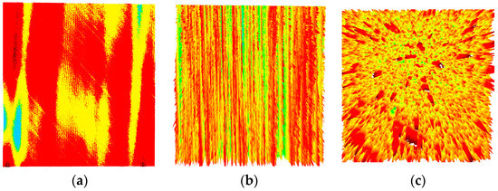
Figure 12.
Rough surface. (a) Polished surface. (b) Ground surface. (c) Shot blasting surface.
The wear levels of the three machined surfaces are shown in Figure 13.
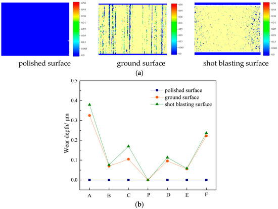
Figure 13.
Wear levels of different machined surfaces. (a) Wear distribution. (b) Wear depth.
The polished surface roughness is small, as shown in Figure 13, and the gear is always in a full-film lubrication state during operation, resulting in no direct contact with solids and no wear. The surface roughness of the ground and shot peening surfaces is high, and the film thickness is of the same order of magnitude as the surface roughness, resulting in a mixed lubrication state and tooth surface wear on both surfaces. Furthermore, the roughness of the grinding surface is slightly less than that of the shot peening surface, and the surface has a transverse texture state. The micro-wedge effect of the transverse texture thickens the grinding surface and reduces wear depth compared to the shot blasting surface [31,32].
Figure 14 illustrates the DMF and DTE of different surfaces after wear.
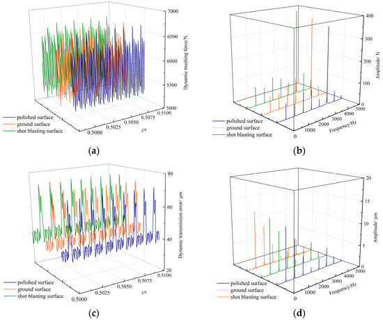
Figure 14.
DMF and DTE of different surfaces. (a) DMF. (b) Frequency domain spectrum. (c) DTE. (d) Frequency domain spectrum.
Figure 15 shows the variation of the peak-to-peak value δp of the dynamic transmission error with the wear time of different surfaces.
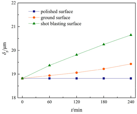
Figure 15.
Variation of the of the δp.
As visible in Figure 15, the different gear lubrication state caused by the tooth surface topography has a greater effect on the gear dynamics. The polished surface’s δp does not change as the running time increases. The wear depth of the ground and shot peened surfaces will accumulate as operating time increases, resulting in an upward trend of δp as operating time increases.
3.3. Effect of Torques on Dynamic Characteristics in Mixed Lubrication Sliding Wear
Because tooth surface load is a strong function of lubricant average film thickness and tooth surface wear, changes in tooth surface tribological properties caused by gear load changes will have a significant impact on gear dynamics. Figure 16 displays the film thickness and contact area ratio under different torques T of 200 to 400 N·m in mixed lubrication sliding wear. The average film thickness on a rough surface is the film thickness within 2/3 times of the Hertz contact radius. The rough direct contact area to the Hertzian contact area is the contact area ratio. The input speed n1 is 1000 r/min.
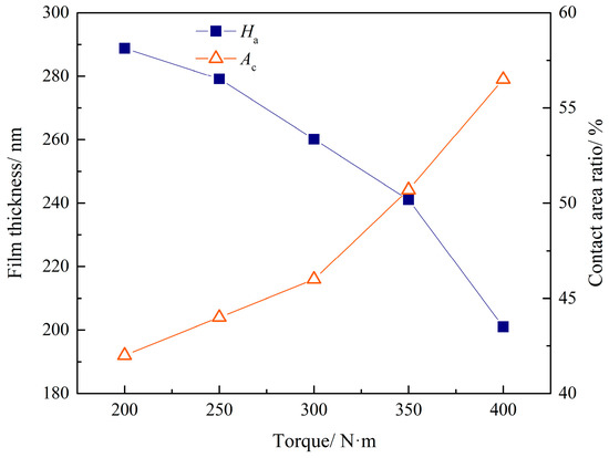
Figure 16.
Film thickness and contact area retio at different torques.
According to Figure 16, increasing gear torque resulted in a decrease in average film thickness between tooth surfaces of approximately 31%, with the rate of this decrease increasing with torque. Simultaneously, as the film thickness decreases, more areas between the contact interfaces are in direct asperity contact, increasing the asperity contact area ratio as the gear torque increases.
The wear degree at different torques is depicted in Figure 17.
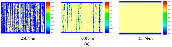
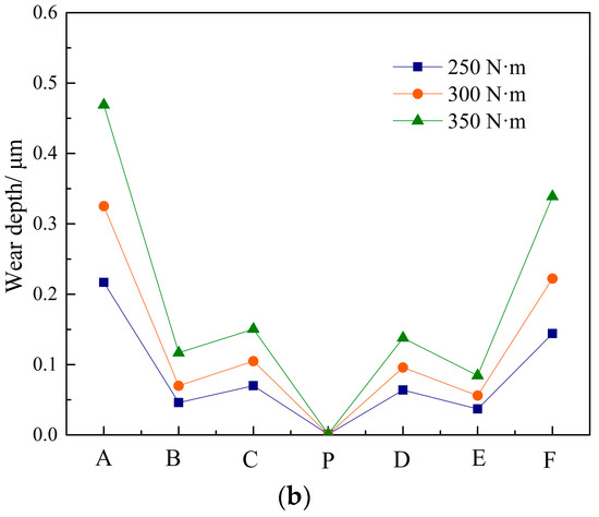
Figure 17.
Wear degree at different torques. (a) Wear distribution. (b) Wear depth.
As shown in Figure 17, increasing torque causes an increase in contact stress, resulting in an increase in wear depth of approximately 80–95%. Furthermore, as torque increases, the rate of increase in wear depth increases. When the torque is low, the load on the tooth surface is low, and the film thickness between the tooth surfaces is thick, resulting in a smaller direct contact area and a lower wear amount. According to Archard’s law, as the torque increases, the film thickness decreases, and the direct asperity area increases, and as the load increases, so does the wear amount.
The effect of torque variation on dynamic characteristics after gear wear is depicted in Figure 18.
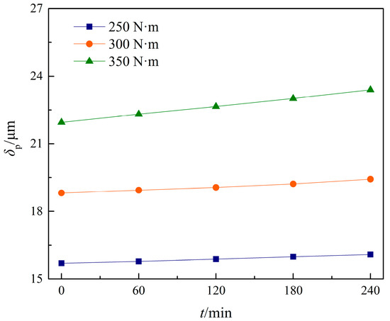
Figure 18.
δp at different torques.
As illustrated in Figure 18, increasing the torque results in a significant increase in δp with the same wear time. Simultaneously, as wear time increases, so does the amount of wear, resulting in a continuous increase of δp, and the effect of wear time on δp is roughly linear. According to Figure 18, as wear time increases, so does the upward trend of δp, indicating that high-load conditions will produce more wear during the same running time, with a more obvious impact on the dynamic characteristics of the system [33].
3.4. Effect of Rotating Speed on Dynamic Characteristics in Mixed Lubrication Sliding Wear
The gear speed influences not only the thickness of the tooth surface, but also the wear characteristics of the tooth surface. Figure 19 depicts the average film thickness and contact area ratio in mixed lubrication sliding wear at various rotating speeds n.
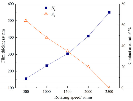
Figure 19.
Film thickness and contact area ratio at different rotating speeds.
According to Figure 19, increasing the rotation speed causes an increase in the entrainment speed between the tooth surfaces, resulting in an increase in the average film thickness, and this trend becomes more pronounced as the rotation speed increases. Simultaneously, the film thickness increases, causing the rough contact area ratio to decrease. The oil film completely separates the two surfaces when the rotational speed is increased to 2500 r/min, and the rough contact area ratio becomes 0.
Figure 20 depicts the wear degree at various rotating speeds.
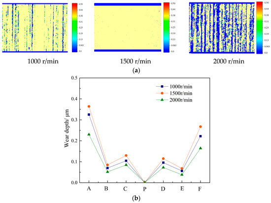
Figure 20.
Wear depth at different rotating speeds. (a) Wear distribution. (b) Wear depth.
In Figure 20, when the gear is in the mixed lubrication state, the wear degree increases first and then decreases with increasing rotational speed, which is clearly different from the dry wear state. This is because, while the contact area ratio decreases when the rotation speed increases from 1000 r/min to 1500 r/min while lubricated, the rotating speed increase leads to a greater effect of the relative speed increase, which causes an increase in the amount of wear. Although the relative speed is higher when the rotating speed is increased to 2000 r/min, the rough contact area between the tooth surfaces is reduced, and the wear amount is also reduced. This is consistent with the findings of Wang et al. [4] in their investigation of helical gear wear.
Figure 21 illustrates the variation of δp with wear time.
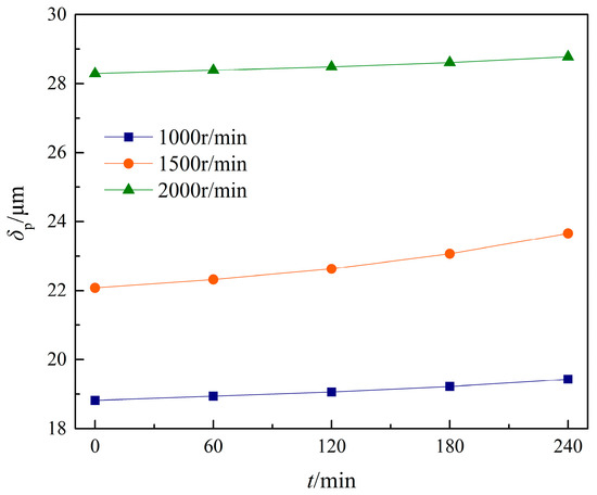
Figure 21.
δp at different rotating speeds.
From Figure 21, increasing rotation speed leads to an increase in δp over the same wear time. Because of the thicker film thickness and lower wear amount, the rate of increase of δp is the slowest when the rotation speed is 2000 r/min. When the rotation speed is 1500r/min, the wear depth changes the most, resulting in the greatest increase in its δp. The increase in δp at 1000 r/min is moderate, indicating that the wear and dynamic characteristics can be improved by choosing a reasonable speed in the gear design.
4. Conclusions
By combining the mixed lubrication sliding wear model with the gear tribology-dynamic model, an analytical model of the dynamic characteristics of the gear taking actual machined tooth surface wear was established. The machined tooth surfaces’ mixed lubrication sliding wear characteristics were investigated. The effects of gear wear depth, dynamic meshing force, and dynamic transmission error on wear form, torque, and rotational speed are discussed.
- (1)
- For the same time period, the wear depth of mixed lubrication sliding wear is 40%-60% less than that of dry contact wear. Meanwhile, the variation in gear meshing stiffness and transmission error caused by lubrication wear is less than that caused by dry contact wear.
- (2)
- Tooth surface wear increases the relative vibration displacement of the gear pair in each frequency band, with the amplitude of the system’s main frequency increasing the most.
- (3)
- As torque increases, film thickness decreases by about 31% and wear depth increases by 80–95%. The peak-to-peak value of gear dynamic transmission error rises as torque rises. With increasing rotating speeds, the wear degree increases first and then decreases, and the peak-to-peak increase rate of gear dynamic transmission error increases first and then decreases.
Author Contributions
Conceptualization, J.Z. and X.Y.; methodology, J.Z.; software, J.Z.; validation, H.Z. and R.Z.; formal analysis, J.Z. and W.S.; investigation, R.Z. and X.Y.; resources, Z.L. and W.S.; data curation, J.Z.; writing—original draft preparation, J.Z.; writing—review and editing, J.Z. and X.Y.; visualization, H.Z.; supervision, Z.L.; project administration, Z.L.; funding acquisition, Z.L. All authors have read and agreed to the published version of the manuscript.
Funding
This research was funded by National Natural Science Foundation of China, 52175053; Defense Industrial Technology Development Program, JCKY2020213B006.
Institutional Review Board Statement
Not applicable.
Informed Consent Statement
Not applicable.
Data Availability Statement
Not applicable.
Acknowledgments
The authors acknowledge the financial support from National Natural Science Foundation of China (52175053), and Defense Industrial Technology Development Program (JCKY2020213B006). The authors also sincerely appreciate the comments and suggestions for modifications made by the editors and anonymous referees.
Conflicts of Interest
The authors declare no conflict of interest.
Nomenclature
| a | Hertzian half width (mm) | rbp, rbg | Base circle radius (mm) |
| Ax | The area of the section | S | Sliding distance (mm) |
| The head clearance coefficient | SR | Slide-roll ratio | |
| E | Effective Young’s modulus (GPa) | Sf | The arc length of the tooth root (mm) |
| e | Static transmission error (μm) | s | The distance from the meshing point to the pitch point (mm) |
| Fm | Meshing force (N) | T | Torque (N·m) |
| Ff | Friction force (N) | U | Entrainment speed (m/s) |
| f | The friction coefficient of solid-to-solid contact | u | Relative sliding velocity (m/s) |
| fpt | Pitch error (μm) | U1, U2 | The velocity of the pinion and gear at contact point (m/s) |
| ff | Tooth profile error (μm) | W1, W2 | wear depth of surface 1 and surface 2 |
| fb | Tooth direction error (μm) | Wc | contact load ratio |
| fa | Center distance installation error (μm) | w | contact load (N/m) |
| H | Material hardness (GPa) | xβ | the distance from the meshing point to the tooth centerline (mm) |
| Ha | Central average film thickness (nm) | yβ | the horizontal distance from the meshing point to the origin (mm) |
| h | Film thickness (nm) | α | Pressure-viscosity coefficient |
| The addendum height coefficient | ν | Poisson’s ratio | |
| hwear | Wear depth (mm) | θ | Torsional angle |
| I | Inertia moment | υ | Elastic deformation |
| Ix | the section moment | The pressure angle of the pitch cycle (°) | |
| k | wear coefficient | ρ | The lubricant density (kg/m3) |
| k1, k2 | The meshing stiffness of the pinion and gear (N/m) | , | The angular velocities of the pinion and gear (rad/s) |
| km and cm | meshing stiffness (N/m) and meshing damping (Ns·m) | η | lubricant viscosity (Pa·s) |
| ka | Axial compression stiffness (N/m) | δ | Relative displacement (μm) |
| kb | Bending stiffness (N/m) | δ1, δ2 | The roughness amplitudes of surface 1 and surface 2 (mm) |
| kf | Tooth base stiffness (N/m) | r | reference radius (mm) |
| kh | Hertz contact stiffness (N/m) | rρ | Fillet radius at the top of the tool (mm) |
| ks | Shear stiffness (N/m) | ||
| kz and cz | Support stiffness (N/m) and support damping (Ns·m) | ||
| L | Tooth width (mm) | ||
| l | Friction arm (mm) | ||
| M | Module (mm) | ||
| m | Quality (kg) | ||
| n1, n2 | Rotational velocity of the pinion and gear (mm) | ||
| p | film pressure (Pa) | ||
| pc | Direct rough contact load (Pa) | ||
| Hertzian contact pressure (Pa) | |||
| R | The equivalent radius of curvature (mm) |
References
- Liu, H.; Liu, H.; Zhu, C.; Tang, J. Study on gear contact fatigue failure competition mechanism considering tooth wear evolution. Tribol. Int. 2020, 147, 106277. [Google Scholar] [CrossRef]
- Liu, H.; Liu, H.; Zhu, C.; Parker, R. Effects of lubrication on gear performance: A review. Mech. Mach. Theory 2020, 145, 82–90. [Google Scholar] [CrossRef]
- Chen, Z.; Ji, P. Research on the variation of mesh stiffness and transmission error for spur gear with tooth profile modification and wear fault. Eng. Fail. Anal. 2021, 122, 105184. [Google Scholar] [CrossRef]
- Wang, H.; Zhou, C.; Lei, Y.; Liu, Z. An adhesive wear model for helical gears in line-contact mixed elastohydrodynamic lubrication. Wear 2019, 426–427, 896–909. [Google Scholar] [CrossRef]
- Zhou, C.; Xing, M.; Hu, B.; Zhaoyao, S. A Modified Wear Model Considering Contact Temperature for Spur Gears in Mixed Elastohydrodynamic Lubrication. Tribol. Lett. 2020, 68, 110. [Google Scholar] [CrossRef]
- Karpat, F.; Ekwaro-Osire, S. Influence of Tip Relief Modification on the Wear of Spur Gears with Asymmetric Teeth. Tribol. Trans. 2008, 51, 581–588. [Google Scholar] [CrossRef]
- Huangfu, Y.; Chen, K.; Ma, H.; Li, X.; Yu, X.; Zhao, B.; Wen, B. Investigation on meshing and dynamic characteristics of spur gears with tip relief under wear fault. Sci. China Technol. Sci. 2019, 62, 1948–1960. [Google Scholar] [CrossRef]
- Liu, G.; Parker, R.G. Impact of tooth friction and its bending effect on gear dynamics. J. Sound Vib. 2009, 320, 1039–1063. [Google Scholar] [CrossRef]
- Feng, K.; Borghesani, P.; Smith, W.A.; Randall, R.B.; Chin, Z.Y.; Ren, J.; Peng, Z. Vibration-based updating of wear prediction for spur gears. Wear 2019, 426–427, 1410–1415. [Google Scholar] [CrossRef]
- Liu, X.; Yang, Y.; Zhang, J. Investigation on coupling effects between surface wear and dynamics in a spur gear system. Tribol. Int. 2016, 101, 383–394. [Google Scholar] [CrossRef]
- Yesilyurt, I.; Gu, F.; Ball, A. Gear tooth stiffness reduction measurement using modal analysis and its use in wear fault severity assessment of spur gears. NDT & E Int. 2003, 36, 357–372. [Google Scholar]
- Ding, H.; Kahraman, A. Interactions between nonlinear spur gear dynamics and surface wear. J. Sound Vib. 2007, 307, 662–679. [Google Scholar] [CrossRef]
- Osman, T.; Velex, P. Static and dynamic simulations of mild abrasive wear in wide-faced solid spur and helical gears. Mech. Mach. Theory 2010, 45, 911–924. [Google Scholar] [CrossRef]
- Yuksel, C.; Kahraman, A. Dynamic tooth loads of planetary gear sets having tooth profile wear. Mech. Mach. Theory 2004, 39, 695–715. [Google Scholar] [CrossRef]
- Wang, X.S.; Wu, S.J.; Zhou, X.H.; Hu, J.C. Nonlinear dynamics analysis of gear transmission system with wear fault. J. Vib. Shock 2013, 32, 37–43. [Google Scholar]
- Shen, Z.; Qiao, B.; Yang, L.; Luo, W.; Yan, R.; Chen, X. Dynamic modeling of planetary gear set with tooth surface wear. Procedia Manuf. 2020, 49, 49–54. [Google Scholar] [CrossRef]
- Zhang, Z.; Zheng, C.; Wen, M.; Yang, S.; Li, H.; Du, Q. A Wear Prediction Model for Spur Gears Based on the Dynamic Meshing Force and Tooth Profile Reconstruction. In Proceedings of the International Conference on Computer Engineering, Information Science & Application Technology, Wuhan, China, 8–9 July 2017; Atlantis Press: Amsterdam, The Netherlands, 2017. [Google Scholar]
- Zhou, C.; Xiao, Z.; Chen, S.; Han, X. Normal and tangential oil film stiffness of modified spur gear with non-Newtonian elastohydrodynamic lubrication. Tribol. Int. 2016, 109, 319–327. [Google Scholar] [CrossRef]
- Shi, X.; Sun, W.; Lu, X.; Ma, X.; Zhu, D.; Zhao, B.; He, T. Three-dimensional mixed lubrication analysis of spur gears with machined roughness. Tribol. Int. 2019, 140, 105864. [Google Scholar] [CrossRef]
- Zhao, J.; Sheng, W.; Li, Z.; Zhang, H.; Zhu, R. Effect of lubricant selection on the wear characteristics of spur gear under oil-air mixed lubrication. Tribol. Int. 2022, 167, 107382. [Google Scholar] [CrossRef]
- Shi, J.L.; Ma, X.G.; Xu, C.L.; Zang, S.J. Meshing Stiffness Analysis of Gear Using the Ishikawa Method. Appl. Mech. Mater. 2013, 401–403, 203–206. [Google Scholar] [CrossRef]
- Wang, H.; Li, Z.; Zhang, B.; Zhu, R. Calculation of static transmission errors associated with thermo-elastic coupling contacts of spur gears. Vibroeng. Procedia 2018, 20, 237–241. [Google Scholar] [CrossRef]
- Wang, H. Research on Key Incentive Calculation Method for Cylindrical Gear Dynamics; Nanjing University of Aeronautics and Astronautics: Nanjing, China, 2019. [Google Scholar]
- Ren, N.; Zhu, D.; Chen, W.; Liu, Y.; Wang, Q. A Three-Dimensional Deterministic Model for Rough Surface Line-Contact EHL Problems. J. Tribol. 2009, 131, 011501. [Google Scholar] [CrossRef]
- Hu, Y.Z.; Wang, H.; Wang, W.Z.; Zhu, D. A computer model of mixed lubrication in point contacts. Tribol. Int. 2001, 34, 65–73. [Google Scholar] [CrossRef]
- Hu, Y.Z.; Zhu, D. A Full Numerical Solution to the Mixed Lubrication in Point Contacts. J. Tribol. 1999, 122, 1–9. [Google Scholar] [CrossRef]
- Liu, S.; Wang, Q.; Liu, G. A versatile method of discrete convolution and FFT (DC-FFT) for contact analyses. Wear 2000, 243, 101–111. [Google Scholar] [CrossRef]
- Zhu, D.; Martini, A.; Wang, W.; Hu, Y.; Lisowsky, B.; Wang, Q.J. Simulation of Sliding Wear in Mixed Lubrication. J. Tribol. 2007, 129, 544–552. [Google Scholar] [CrossRef]
- Zhu, D.; Liu, Y.; Wang, Q. On the Numerical Accuracy of Rough Surface EHL Solution. Tribol. Trans. 2014, 57, 570–580. [Google Scholar] [CrossRef]
- Zhao, J.; Li, Z.; Zhang, H.; Zhu, R. Effect of micro-textures on lubrication characteristics of spur gears under 3D line-contact EHL model. Ind. Lubr. Tribol. 2021, 73, 1132–1145. [Google Scholar] [CrossRef]
- Pu, W. Effect of surface topography associated with arbitrary velocity direction on the lubrication film thickness in elliptical contacts. Ind. Lubr. Tribol. 2018, 70, 444–452. [Google Scholar] [CrossRef]
- Yan, X.-L.; Wang, X.-L.; Zhang, Y.-Y. A Parametric Study on Fatigue Life for Mixed Elastohydrodynamic Lubrication Point Contacts. J. Tribol. 2013, 135, 04150. [Google Scholar] [CrossRef]
- Zhou, S.; Song, G.; Sun, M.; Ren, Z. Nonlinear dynamic response analysis on gear-rotor-bearing transmission system. J. Vib. Control 2016, 24, 1632–1651. [Google Scholar] [CrossRef]
Disclaimer/Publisher’s Note: The statements, opinions and data contained in all publications are solely those of the individual author(s) and contributor(s) and not of MDPI and/or the editor(s). MDPI and/or the editor(s) disclaim responsibility for any injury to people or property resulting from any ideas, methods, instructions or products referred to in the content. |
© 2022 by the authors. Licensee MDPI, Basel, Switzerland. This article is an open access article distributed under the terms and conditions of the Creative Commons Attribution (CC BY) license (https://creativecommons.org/licenses/by/4.0/).