Abstract
Nonlinear multi-stable piezoelectric energy harvesters show broadband frequency spectra and excellent energy harvesting performance, owing to their high output power related to inter-well transitions. However, existing quad-stable piezoelectric energy harvesters contain too many structural parameters, which makes the systems clumsy, and increases the difficulties of dynamic analysis and structural optimization. Herein, a nonlinear quad-stable piezoelectric energy harvester, with only one external magnet, is proposed based on the magnetic force characteristics between a ring magnet and a rectangular magnet. Under selected structural parameters, as the magnet spacing increases, the stability characteristic of the harvester changes from quad-stability to bi-stability, and then to mono-stability. The transformation of the stability characteristic results from the changes in the variation rate of the vertical magnetic force. Subsequently, under the filtered Gaussian white noise within the frequency range of 0–120 Hz, the energy harvesting performance of the harvester is simulated by the classic fourth-order Runge-Kutta method. Simulation results show that the performance of the harvester under the quad-stable structural parameters is better than that under the bi-stable structural parameters, independent of whether the excitation acceleration is small or large. This result is related to the potential well characteristics under the quad-stable and bi-stable structural parameters. More specifically, the potential well depths under the quad-stable and bi-stable structural parameters are almost the same, but the distance between the two outer potential wells under the quad-stable structural parameters is larger than that under the bi-stable structural parameters. Finally, a fabricated prototype is used to measure the experimental performance of the harvester. The experimental data and the estimated data share the same trend. This study provides a new conception and technical method for the design, optimization, and application of quad-stable piezoelectric energy harvesters.
1. Introduction
With the rapid development of flexible electronic systems and low-power wireless sensors for the Internet of Things (IoT), energy harvesters have attracted considerable attention [1,2,3]. This is because energy harvesters can convert ambient energy from such sources as heat, water flow, wind, solar, and mechanical vibration into electric energy for supplying power to electronic devices [4,5,6]. More importantly, they can be used in harsh environments, where conventional chemical batteries may not work properly because of difficulties in charging or replacement, including the deep sea, wide deserts, interiors of nuclear reactors, and high walls of skyscrapers [7,8]. Mechanical vibration is widely present in aerospace and transportation systems, industrial machinery, and human movement [9,10]. Hence, numerous design patterns of mechanical energy harvesters have been proposed based on different energy conversion mechanisms: electromagnetic [11,12], electrostatic [13,14], magnetostrictive [15,16], triboelectric [17,18], and piezoelectric [19,20]. Among them, piezoelectric energy harvesting has drawn much attention because of its high energy density and superior electromechanical energy conversion efficiency [21,22,23].
For the piezoelectric energy harvesters, frequency bandwidth is an important parameter. A linear structure only exhibits the best output performance at its natural frequency, which leads to a narrowband response [24,25]. Hence, a variety of strategies are used to increase the effective bandwidth, such as multiple resonator arrays [26,27], frequency upconversion [28,29], and nonlinear techniques [30,31]. Among the nonlinear techniques, multi-stable piezoelectric energy harvesters, which mainly include bi-stable piezoelectric energy harvesters (BPEHs), tri-stable piezoelectric energy harvesters (TPEHs), and quad-stable piezoelectric energy harvesters (QPEHs), show broadband frequency spectra and excellent energy harvesting performance because of their high output power related to inter-well transitions.
The multi-stability of a nonlinear piezoelectric energy harvester can be realized by mechanical preloading. Masana and Daqaq [32,33] exploited the super-harmonic frequency bands of a mechanical preloaded BPEH to collect energy. Qian et al. [34] designed a buckled preloaded BPEH, which could harvest vibration energy in a wide frequency range. Inspired by the rapid shape transition of the Venus flytrap, they then designed and investigated a low-cost preloaded BPEH to collect potential mechanical energy [35]. In addition, nonlinear multi-stability can also be realized by residual thermal stress in a laminate composite [36,37]. Arrieta et al. [38] introduced a cantilevered piezoelectric bi-stable composite, which could exploit the large strains close to the clamped end for broadband energy harvesting. Li et al. [39] proposed a low-frequency bi-stable vibration energy harvesting plate with good performance, whose power is higher than 1 mW. Firouzian-Nejad et al. [40,41] experimentally investigated the characteristic system parameters of bi-stable hybrid composite laminates.
However, mechanical preloaded harvesters are usually accompanied by additional constraints that make the systems complex. For laminate composites, the manufacturing processes are complicated; moreover, they are sensitive to temperature and humidity, thereby causing the changes of their material properties after extended service [35]. A simple way to overcome these disadvantages and construct nonlinear multi-stability is through the use of magnetic interaction, which has been adopted by many researchers. Ferrari et al. [42] explored the energy harvesting characteristics of a traditional BPEH consisting of a rigid-support external magnet, a piezoelectric cantilever beam, and a tip magnet, discovering that under proper conditions, the BPEH exhibits better output performance than linear structures. According to Leng et al. [43], who compared an elastic-support BPEH with a rigid-support device, and found that the elastic-support BPEH could more easily adapt to random excitations with variable intensity. Wang et al. [44] proposed a BPEH with an elastic magnifier. Compared with a traditional BPEH, it could generate higher output through changing system parameters. Zhou et al. [45] constructed a traditional broadband TPEH with two external magnets, exhibiting a wider operational bandwidth than a traditional BPEH using magnetic interaction under low-level excitations. Cao et al. [46] analyzed the effects of potential well depth on the output performance of a TPEH. Leng et al. [47] used the magnetizing current method to compute the magnetic force of a TPEH, proving that compared to a BPEH, the TPEH significantly improves the output voltage. Zhou et al. [48,49] developed a typical QPEH composed of a piezoelectric cantilever beam, a tip magnet, and three external magnets, which could obtain higher output voltage than a typical BPEH. Mei et al. [50] utilized a typical QPEH to harvest energy in rotational motion, proving that the QPEH has a wider operational bandwidth of 1–7 Hz, compared with that of a BPEH of 3–7.3 Hz, and a TPEH of 4–7.3 Hz, respectively. Ju et al. [51] investigated the influence of the geometric nonlinearity of the piezoelectric beam on the performance of a typical QPEH. Zou et al. [52] designed a QPEH with a piezoelectric beam and a cam-roller-spring structure, in which the coordinates of the equilibrium points were programmable. Wang et al. [53] conceived a wideband QPEH induced by the surface contact and magnetic interaction, proving that the operational bandwidth of the harvester is extended to a low frequency range.
However, the QPEHs in Refs. [48,49,50,51] contain three external magnets; that in Ref. [52] contains a cam-roller-spring structure, and that in Ref. [53] contains two external magnets and a contact surface. Obviously, these harvesters contain too many structural parameters, which make the systems clumsy, thereby increasing the difficulties of dynamic analysis and structural optimization. Additionally, multiple components are not conducive to the installation and adjustment of the energy harvester. To address these issues, here a novel nonlinear QPEH with only one external magnet is constructed. In this design, the nonlinear quad-stability is ingeniously realized through the interaction of a ring magnet on a base wall with a rectangular magnet at the end of a cantilever beam. This QPEH simplifies the system design, dynamic analysis, installation, and debugging. The remainder of the paper is organized as follows. Section 2 introduces and models the QPEH, and obtains its governing equations, as well as its potential energy function. Section 3 simulates the potential energy, magnetic force, and energy harvesting performance of the QPEH. In Section 4, experiments are carried out to measure the performance of the QPEH. The discussion and conclusions are presented in Section 5 and Section 6, respectively.
2. Configuration and Model
Figure 1 shows the nonlinear QPEH, with only one external magnet, which is composed of a rectangular magnet A (tip magnet), a piezoelectric cantilever beam C, with a piece of macro-fiber composite (MFC) attached, and a base D, on which a ring magnet B (external magnet) is fixed. The magnet spacing between the two magnets is d. Aligned horizontally, the two magnets are mutually repulsive at the origin point O (see Figure 1b), if gravity is not considered. Under certain structural parameters, the system owns four stable equilibrium points, thereby achieving quad-stable transitions under appropriate excitations.

Figure 1.
Schematics of the nonlinear QPEH with only one external magnet: (a) three-dimensional schematic; (b) two-dimensional schematic.
The lumped parameter method is used to simplify the harvester to an equivalent mass-spring-damping model [43,45,46,47,48,49,50]. The governing equations of the equivalent model are obtained from Newton’s second law and Kirchhoff’s first law [54,55]:
where PA represents the external excitation force; Fi represents the vertical magnetic force between the two magnets; xA represents the vertical displacement of the tip magnet, as shown in Figure 1b; Meq, Keq, and ηeq are the equivalent mass, equivalent stiffness, and equivalent damping, respectively; θ represents the electromechanical coupling coefficient; U represents the output voltage; CP represents the equivalent capacitance of the piezoelectric patch; and RL represents the external resistance.
In Equations (1) and (2), PA is determined by the external vibration source; Meq and Keq, whose calculation equations can be found in Ref. [56], are determined by the dimensions and materials of the cantilever beam substrate, piezoelectric patch, and tip magnet; CP is measured by a capacitance meter; ηeq and θ are chosen to make the estimated data (xA and U) better match the experimental figures. Fi can be calculated by the magnetizing current method, and its equation is available in Refs. [57,58]:
where MA represents the magnetization of the tip magnet; Bj and Bk are the magnetic induction intensity in the y and z directions generated by the external magnet B (see Figure 1), respectively; S1, S2, S3, and S4 are the upper, lower, front, and rear surface areas of the tip magnet, respectively; α represents the deflection angle of the tip magnet when the beam bends. Bj and Bk can be expressed as [57,58]:
where MB represents the magnetization of the external magnet; μ0 is the vacuum permeability; tB is the thickness of the external magnet; and R1 and R2 are the outer circle radius and the inner circle radius of the external magnet, respectively.
The y–z plane (see Figure 1) is defined as the zero potential energy surface, and the total potential energy of the system Vp is:
where W1 represents the work performed by the equivalent linear elastic force FL, and W2 represents the work performed by the vertical magnetic force Fi. In Equation (6), gravity is ignored, because the direction of gravity is perpendicular to that of the motion of the cantilever, as shown in the experimental setup in Section 4; the horizontal magnetic force is also ignored, because the harvester is simplified to a model with one degree of freedom.
Accordingly, the power of the external resistance P can be expressed as:
where Urms is the root mean square (RMS) value of the output voltage U over a period of time.
3. Numerical Simulation
In this section, in order to imitate low frequency noise sources in the environment, the external excitation force PA is defined as the filtered Gaussian white noise within the frequency range of 0–120 Hz. Excitation acceleration aArms represents the intensity of PA, and it can be calculated by:
where PArms is the RMS value of PA over a period of time. Table 1 shows the structural parameters of the QPEH. In Table 1, the density and Young’s modulus of the cantilever beam substrate, piezoelectric patch, tip magnet, and external magnet are dependent on their materials, while their dimensions are measured by the experiments, and 30 MΩ (RL) is used to estimate the open circuit voltage of the QPEH.

Table 1.
Structural parameters of the QPEH.
3.1. Potential Energy and Magnetic Force of the QPEH
Inserting the structural parameters in Table 1 into Equations (3)–(6), the potential energy function and magnetic force equation are numerically solved by MATLAB, as shown in Figure 2.
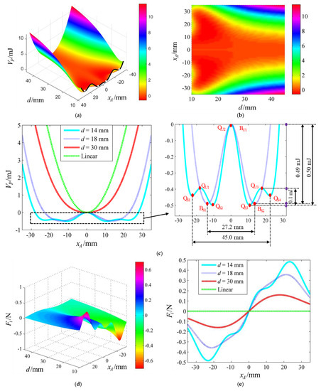
Figure 2.
(a) The potential energy Vp varying with the vertical displacement xA and magnet spacing d; (b) the projection of Vp in the xA–d plane; (c) Vp–xA curves when d = 14, 18, and 30 mm, and the harvester is in the linear state; (d) the vertical magnetic force Fi varying with xA and d; (e) Fi–xA curves when d = 14, 18, and 30 mm, and the harvester is in the linear state.
Figure 2a shows the potential energy Vp varying with the vertical displacement xA and magnet spacing d; Figure 2b shows the projection of Vp in the xA–d plane; and Figure 2c shows Vp–xA curves when d = 14, 18, and 30 mm, and the harvester is in the linear state. As illustrated in Figure 2a–c, when the magnet spacing d is small, such as d = 14 mm, the QPEH presents the quad-stable characteristic, and there are four stable equilibrium points (QS1, QS2, QS3, and QS4), and three unstable equilibrium points (QU1, QU2 and QU3). With the increase in d, such as d = 18 mm, the two outer shallower potential wells disappear and the system changes to the bi-stable state, thereby owning two stable equilibrium points (BS1 and BS2) and an unstable equilibrium point (BU1). If d continues to increase, such as d = 30 mm, the two remaining potential wells change into one, and the system reaches the mono-stable state. There is no doubt that when d is large enough, the system is infinitely close to the linear state. Here, note that 14, 18, and 30 mm are chosen to show different stability characteristics to better conduct the simulation and experimental comparative analyses.
Figure 2d shows the vertical magnetic force Fi varying with the vertical displacement xA and magnet spacing d, and Figure 2e shows Fi–xA curves when d = 14, 18, and 30 mm, and the harvester is in the linear state. As shown in Figure 2d,e, for xA > 0, when d = 14, 18, and 30 mm, Fi first increases and then decreases, but the variation rate of Fi is different; when the harvester is linear, Fi is zero.
According to Equation (6), the stability characteristic of the harvester varies with the equivalent linear elastic force and vertical magnetic force. When the piezoelectric beam is selected, its equivalent stiffness is invariant, so the trend of the equivalent linear elastic force varying with the vertical displacement remains unchanged. Therefore, the stability characteristic of the harvester is affected only by the vertical magnetic force. At different magnet spacings, the variation rate of the vertical magnetic force is different (see Figure 2e), which results in the different stability characteristics.
3.2. Estimated Energy Harvesting Performance of the QPEH
Figure 3 shows the estimated Urms–aArms curves when aArms falls within the range of 0.71–1.77 g. It is obvious that the estimated RMS value of the open circuit voltage under the quad-stable structural parameters is larger than that under the bi-stable structural parameters when the acceleration falls within the range of 0.71–1.77 g.
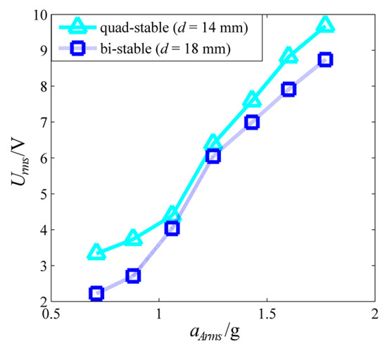
Figure 3.
Estimated Urms−aArms curves when aArms falls within the range of 0.71–1.77 g.
Figure 4 shows the output displacement, open circuit voltages, phase portraits, and power spectrum densities (PSDs) of the voltages under the quad-stable and bi-stable structural parameters when aArms = 0.88 g. As shown in Figure 4(a1–d2), when aArms = 0.88 g, the harvester achieves one-sided bi-stable inter-well movement under the quad-stable structural parameters, while it only vibrates in a single potential well under the bi-stable structural parameters; the Urms values under the quad-stable and bi-stable structural parameters are 3.74 and 2.71 V, respectively; the ranges of the output displacement under the quad-stable and bi-stable structural parameters are −28.2–−1.6 and −23.6–−0.3 mm, respectively; the amplitude of the PSD of the voltage under the quad-stable structural parameters is greater than that under the bi-stable structural parameters within the frequency range of 0–3 Hz.
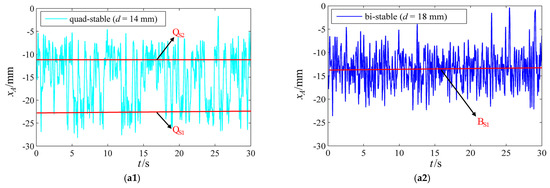
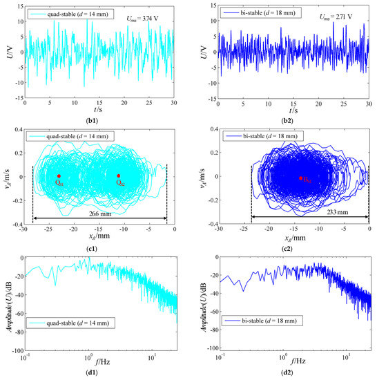
Figure 4.
The (a1) output displacement, (b1) open circuit voltage, (c1) phase portrait, and (d1) PSD of the voltage under the quad-stable structural parameters when aArms = 0.88 g; the (a2) output displacement, (b2) open circuit voltage, (c2) phase portrait, and (d2) PSD of the voltage under the bi-stable structural parameters when aArms = 0.88 g.
Figure 5 shows the output displacement, open circuit voltages, phase portraits, and PSDs of the voltages under the quad-stable and bi-stable structural parameters when aArms = 1.6 g. As depicted in Figure 5(a1–d2), when aArms = 1.6 g, the harvester achieves two-sided quad-stable inter-well movement under the quad-stable structural parameters, while it achieves two-sided bi-stable inter-well movement under the bi-stable structural parameters; the Urms values under the quad-stable and bi-stable structural parameters are 8.82 and 7.91 V, respectively; the ranges of the output displacement under the quad-stable and bi-stable structural parameters are −32.1–30.7 and −28.3–25.0 mm, respectively; the amplitude of the PSD of the voltage under the quad-stable structural parameters is greater than that under the bi-stable structural parameters within the frequency range of 0–3 Hz.
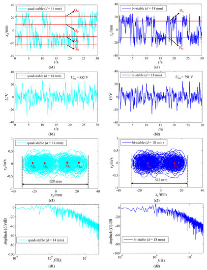
Figure 5.
The (a1) output displacement, (b1) open circuit voltage, (c1) phase portrait, and (d1) PSD of the voltage under the quad-stable structural parameters when aArms = 1.6 g; the (a2) output displacement, (b2) open circuit voltage, (c2) phase portrait, and (d2) PSD of the voltage under the bi-stable structural parameters when aArms = 1.6 g.
Clearly, with the increase in acceleration, the output displacement, open circuit voltage, and its PSD amplitude increase. More importantly, the energy harvesting performance under the quad-stable structural parameters is better than that under the bi-stable structural parameters, whether aArms = 0.88 or 1.6 g. This result is dependent on the potential well characteristics under the quad-stable and bi-stable structural parameters. In Figure 2c, the vertical depth (or the barrier height) between QS3 and QU3 is 0.1 mJ; the vertical depth between QU2 and QS3 is 0.5 mJ; the vertical depth between BU1 and BS2 is 0.49 mJ; the horizontal width between QS1 and QS4 is 45 mm; the horizontal width between BS1 and BS2 is 27.2 mm. When aArms = 0.88 g, the input energy provided by the external excitation is greater than 0.1 mJ, but smaller than 0.49 mJ, so under the quad-stable structural parameters, the system moves between the two potential wells on one side, while under the bi-stable structural parameters, it only achieves intra-well motion. When aArms = 1.6 g, the input energy is greater than 0.5 mJ, so the system under both the quad-stable and bi-stable structural parameters can achieve inter-well movement, and the amplitude under the quad-stable structural parameters is greater than that under the bi-stable structural parameters, because 45 > 27.2 mm. Consequently, when either aArms = 0.88 or 1.6 g, the system under the quad-stable structural parameters has greater oscillation amplitude and higher output voltage, thereby presenting better energy harvesting performance. In other words, the larger the distance between the two outer potential wells and the shallower the potential well depth, the more energy is collected.
Figure 6 shows the voltage–external resistance and power–external resistance curves when aArms = 1.6 g. For both the quad-stable and bi-stable structural parameters, the output voltage becomes increasingly greater with the increase in external resistance, while the output power first increases, and then decreases. This trend is linked to the circuit characteristics of the QPEH. According to Equation (2), the system circuit is based on the RC parallel circuit. Figure S1 shows the voltage and power characteristics of the RC parallel circuit. Hence, for a certain capacitive reactance RC, the output voltage becomes greater and greater with the increase in the external resistance RL, while the maximum power can be obtained if, and only if, the external resistance RL is equal to the capacitive reactance RC. The maximum power of 3.62 µW at 8 MΩ under the quad-stable structural parameters is higher than that of 3.11 µW at 6 MΩ under the bi-stable structural parameters.
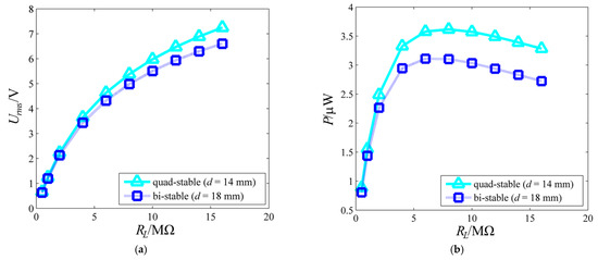
Figure 6.
Estimated voltage and power varying with resistance load RL under the quad-stable and bi-stable structural parameters when aArms = 1.6 g: (a) Urms−RL curves; (b) P−RL curves.
4. Experimental Verification
To verify whether the above theoretical analyses are correct, relevant experiments are carried out to measure the performance of the QPEH. Table 1 shows the parameters of the experimental materials.
4.1. Experimental Setup
In Figure 7a, the QPEH is fixed on the vibration exciter (YMC VT-200). The filtered Gaussian white noise used in the computation is input into the signal generator (Agilent 33500B) through a U disk. Then, it is amplified by the power amplifier (YMC LA-200). The excitation level can be adjusted by controlling the signal generator. Computer A can display and store the displacement signals of the QPEH measured by the laser displacement sensor and its data acquisition device (LK-G5001V); computer B can display and store the acceleration signals of the QPEH measured by the acceleration sensor (LC0103TA) and its data acquisition device (NI PXI-1033); the oscilloscope (TBS 1104) can display and store the voltage signals of the QPEH. In the experiment, the magnet spacing under the quad-stable structural parameters is 11 mm, while that under the bi-stable structural parameters is 15 mm. Here, note that due to errors (see Section 5), the experimental magnet spacing cannot be exactly the same as the estimated magnet spacing.
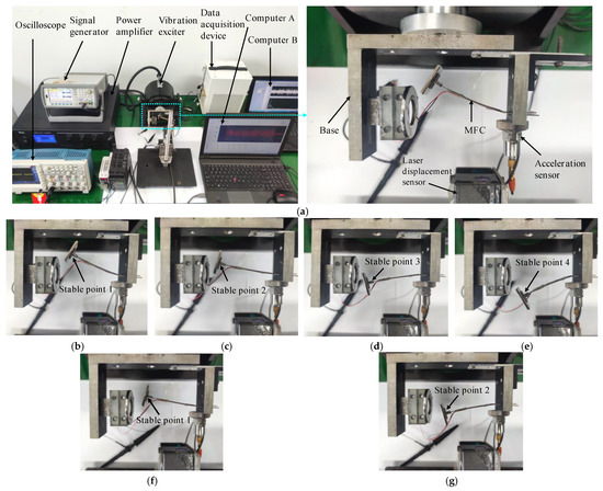
Figure 7.
(a) The experimental setup; the stable equilibrium points of the energy harvester under the quad-stable structural parameters (d = 11 mm): (b) stable point 1, (c) stable point 2, (d) stable point 3, and (e) stable point 4; the stable equilibrium points of the energy harvester under the bi-stable structural parameters (d = 15 mm): (f) stable point 1 and (g) stable point 2.
4.2. Experimental Energy Harvesting Performance of the QPEH
Figure 8 shows the experimental Urms−aArms curves when aArms falls within the range of 0.66–1.74 g. Obviously, the experimental RMS value of the open circuit voltage under the quad-stable structural parameters is larger than that under the bi-stable structural parameters, when the acceleration falls within the range of 0.66–1.74 g. The trend of the experimental data is the same as that of the estimated figures.
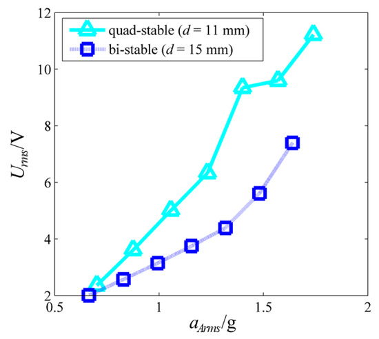
Figure 8.
Experimental Urms−aArms curves when aArms falls within the range of 0.66–1.74 g.
Figure 9 shows the experimental output displacement, open circuit voltages, phase portraits, and PSDs of the voltages under the quad-stable structural parameters when aArms = 0.88 g, and the bi-stable structural parameters when aArms = 0.99 g. It is important to note here that the excitation accelerations under the quad-stable and bi-stable structural parameters cannot be the same in the experiment as those in the estimation, because the signal generator and power amplifier need to be readjusted when the magnet spacing is adjusted. As shown in Figure 9(a1–d2), the system achieves one-sided bi-stable inter-well movement (see Video S1) under the quad-stable structural parameters when aArms = 0.88 g, but it only vibrates in a single potential well under the bi-stable structural parameters when aArms = 0.99 g; the Urms values under the quad-stable and bi-stable structural parameters are 3.6 and 3.16 V, respectively; the ranges of the output displacement under the quad-stable and bi-stable structural parameters are −24.8–−0.4 and −18.4–−0.8 mm, respectively; the amplitude of the PSD of the voltage under the quad-stable structural parameters is greater than that under the bi-stable structural parameters within the frequency range of 0–3.8 Hz.
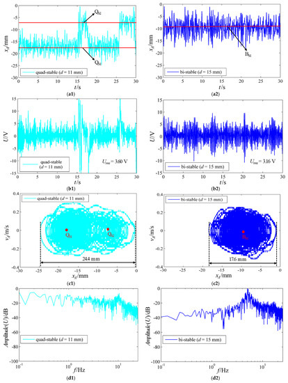
Figure 9.
The experimental (a1) output displacement, (b1) open circuit voltage, (c1) phase portrait, and (d1) PSD of the voltage under the quad-stable structural parameters when aArms = 0.88 g; the (a2) output displacement, (b2) open circuit voltage, (c2) phase portrait, and (d2) PSD of the voltage under the bi-stable structural parameters when aArms = 0.99 g.
Figure 10 shows the experimental output displacement, open circuit voltages, phase portraits, and PSDs of the voltages under the quad-stable structural parameters when aArms = 1.57 g, and the bi-stable structural parameters when aArms = 1.64 g. As depicted in Figure 10(a1–d2), the system achieves two-sided quad-stable inter-well movement (see Video S2) under the quad-stable structural parameters when aArms = 1.57 g, and it achieves two-sided bi-stable inter-well movement (see Video S3) under the bi-stable structural parameters when aArms = 1.66 g; the Urms values under the quad-stable and bi-stable structural parameters are 9.55 and 7.3 V, respectively; the ranges of the output displacement under the quad-stable and bi-stable structural parameters are −28.8–30.1 and −25.3–20.9 mm, respectively; the amplitude of the PSD of the voltage under the quad-stable structural parameters is greater than that under the bi-stable structural parameters within the frequency range of 0–4.4 Hz.
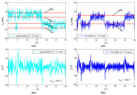
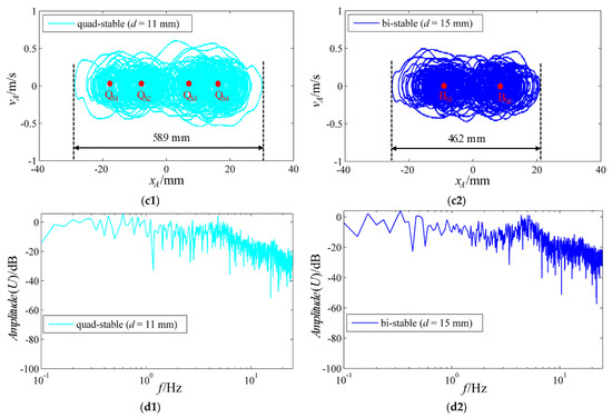
Figure 10.
The experimental (a1) output displacement, (b1) open circuit voltage, (c1) phase portrait, and (d1) PSD of the voltage under the quad-stable structural parameters when aArms = 1.57 g; the (a2) output displacement, (b2) open circuit voltage, (c2) phase portrait, and (d2) PSD of the voltage under the bi-stable structural parameters when aArms = 1.64 g.
As expected, when the excitation level increases, the experimental output displacement, open circuit voltage, and its PSD amplitude increase. Moreover, the experimental energy harvesting performance under the quad-stable structural parameters when aArms = 0.88 and 1.57 g is better than that under the bi-stable structural parameters when aArms = 0.99 and 1.64 g, respectively. The experimental results are consistent with the estimated results.
Figure 11 shows the experimental voltage–external resistance and power–external resistance curves under the quad-stable structural parameters when aArms = 1.49 g, and the bi-stable structural parameters when aArms = 1.56 g. Unsurprisingly, for both the quad-stable and bi-stable structural parameters, the output voltage becomes increasingly greater with the increase in external resistance, while the output power first increases, and then decreases. This is the same trend as that of the estimated data. The maximum power 19.43 µW at 0.75 MΩ under the quad-stable structural parameters is higher than the 11.76 µW at 0.47 MΩ under the bi-stable structural parameters.
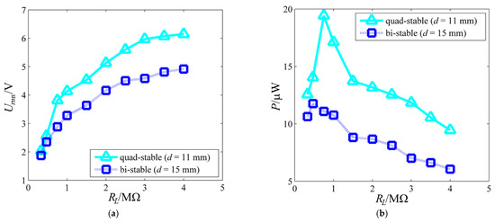
Figure 11.
Experimental voltage and power variation with resistance load RL under the quad-stable structural parameters when aArms = 1.49 g and the bi-stable structural parameters when aArms = 1.56 g: (a) Urms−RL curves; (b) P−RL curves.
5. Discussion
A novel nonlinear quad-stable piezoelectric energy harvester with only one external magnet is constructed by means of the magnetic interaction between a ring magnet and a rectangular magnet. By adjusting the magnet spacing, the multi-stability of the harvester can be changed. This is due to the fact that the variation rate of the vertical magnetic force changes with the magnet spacing, while the equivalent stiffness of the piezoelectric beam remains unchanged.
A comparison between Figure 3, Figure 4, Figure 5, Figure 6, Figure 8, Figure 9, Figure 10 and Figure 11 shows the consistency of the overall trend of the experiment and computation. However, the experimental magnet spacing, excitation acceleration, output displacement, open circuit voltage, and output power cannot precisely coincide with the estimated figures. Firstly, in the computation, d = 14 and 18 mm are selected for the quad-stable parameter and bi-stable parameter, respectively, while in the experiment, d = 11 and 15 mm are selected for the quad-stable parameter and the bi-stable parameter, respectively. Secondly, the estimated open circuit voltage under the quad-stable parameter ranges from 3.34 to 9.68 V, and that under the bi-stable parameter ranges from 2.22 to 8.74 V, when the acceleration falls within the range of 0.71–1.77 g; the experimental output voltage under the quad-stable parameter ranges from 2.36 to 11.22 V, and that under the bi-stable parameter ranges from 2 to 7.4 V, when the excitation acceleration falls within the range of 0.66–1.74 g. Finally, the experimental maximum power is greater than the estimated figure, and the experimental optimal matching resistance is lower than the estimated figure (see Figure 6b and Figure 11b). These differences are caused by an abundance of errors, which mainly include model errors and positioning errors.
In modeling, the horizontal displacement yA (see Figure 1b) is neglected, and the harvester is simplified to an equivalent model, with only one degree of freedom, so the horizontal magnetic force is ignored, but in the experiment, the system has two degrees of freedom, and there is a horizontal magnetic force. The horizontal magnetic force affects the potential energy of the system and changes the positions of the stable equilibrium points.
In addition, for the fabricated QPEH, the experimental coordinate system cannot precisely correspond to the simulation system; therefore, there are positioning errors. The positioning errors also cause the differences between the experiment and computation. Therefore, the experimental data are not precisely the same as the estimated data.
6. Conclusions
Based on the magnetic force characteristics between a ring magnet and a rectangular magnet, a nonlinear quad-stable piezoelectric energy harvester, with only one external magnet, can be constructed. With the increase in magnet spacing, the stability characteristic of the harvester changes from quad-stability to bi-stability, and then to mono-stability, which is caused by the changes in the variation rate of the vertical magnetic force.
Using the filtered Gaussian white noise within the frequency range of 0–120 Hz, the energy harvesting performance under the quad-stable structural parameters is better than that under the bi-stable structural parameters, independent of whether the excitation acceleration is small or large. When the excitation acceleration is small, the harvester achieves one-sided bi-stable inter-well movement under the quad-stable structural parameters, while it only vibrates in a single potential well under the bi-stable structural parameters; when the excitation acceleration is large, the harvester achieves two-sided quad-stable inter-well movement under the quad-stable structural parameters, while it achieves two-sided bi-stable inter-well movement under the bi-stable structural parameters. The result depends on the potential well characteristics under the quad-stable and bi-stable structural parameters. The potential well depths under the quad-stable and bi-stable structural parameters are almost the same, but the distance between the two outer potential wells under the quad-stable structural parameters is larger than that under the bi-stable structural parameters. In other words, the larger the distance between the two outer potential wells and the shallower the potential well depth, the more energy is collected. In addition, for both the quad-stable and bi-stable structural parameters, the output voltage becomes increasingly larger with the increase in external resistance, while the output power first increases, and then decreases, due to the RC parallel circuit characteristics of the harvester.
This work provides a new conception and technical method for the design, optimization, and application of multi-stable piezoelectric energy harvesters.
Supplementary Materials
The following supporting information can be downloaded at: https://www.mdpi.com/article/10.3390/machines10090803/s1, Figure S1: The equivalent RC parallel circuit of the harvester; Video S1: One-sided bi-stable inter-well movement; Video S2: Two-sided quad-stable inter-well movement; Video S3: Two-sided bi-stable inter-well movement.
Author Contributions
Conceptualization, S.S. and Y.L.; methodology, S.S.; software, S.S.; validation, S.S., S.H. and X.S.; formal analysis, S.S., S.H. and X.S.; resources, Y.L., S.H., H.-C.S. and C.-Y.K.; writing—original draft preparation, S.S., Y.L., S.H. and F.S.; writing—review and editing, S.S., Y.L., S.H. and F.S.; supervision, Y.L., H.-C.S. and C.-Y.K.; funding acquisition, Y.L., S.H. and H.-C.S. All authors have read and agreed to the published version of the manuscript.
Funding
This research was funded by the National Natural Science Foundation of China (Grant Nos. 52275122 and 12132010), the Energy Technology Development Project (KETEP) grant funded by the Ministry of Trade, Industry, and Energy, Republic of Korea (Project No. 2018201010636A), and the Korea Institute of Science and Technology (KIST) Young Fellow Program (Project No. 2V09113).
Data Availability Statement
The datasets used and analyzed during the current study are available from the corresponding author on reasonable request.
Acknowledgments
S.S. acknowledges support from the China Scholarship Council (File No. 202106250074).
Conflicts of Interest
The authors declare no conflict of interest.
References
- Orrego, S.; Shoele, K.; Ruas, A.; Doran, K.; Caggiano, B.; Mittal, R.; Kang, S. Harvesting ambient wind energy with an inverted piezoelectric flag. Appl. Energy 2017, 194, 212–222. [Google Scholar] [CrossRef]
- Lim, K.; Peddigari, M.; Park, C.; Lee, H.; Min, Y.; Kim, J.; Ahn, C.; Choi, J.; Hahn, B.; Choi, J.; et al. A high output magneto-mechano-triboelectric generator enabled by accelerated water-soluble nano-bullets for powering a wireless indoor positioning system. Energy Environ. Sci. 2019, 12, 666–674. [Google Scholar] [CrossRef]
- Peddigari, M.; Kwak, M.; Min, Y.; Ahn, C.; Choi, J.; Hahn, B.; Choi, C.; Hwang, G.; Yoon, W.; Jang, J. Lifetime estimation of single crystal macro-fiber composite-based piezoelectric energy harvesters using accelerated life testing. Nano Energy 2021, 88, 106279. [Google Scholar] [CrossRef]
- Hannan, M.; Mutashar, S.; Samad, S.; Hussain, A. Energy harvesting for the implantable biomedical devices: Issues and challenges. BioMed. Eng. Online 2014, 13, 79. [Google Scholar] [CrossRef]
- Hwang, G.; Park, H.; Lee, J.; Oh, S.; Park, K.; Byun, M.; Park, H.; Ahn, G.; Jeong, C.; No, K.; et al. Self-powered cardiac pacemaker enabled by flexible single crystalline PMN-PT piezoelectric energy harvester. Adv. Mater. 2014, 26, 4880–4887. [Google Scholar] [CrossRef]
- Lai, Z.; Xu, J.; Bowen, C.; Zhou, S. Self-powered and self-sensing devices based on human motion. Joule 2022, 6, 1501–1565. [Google Scholar] [CrossRef]
- Jung, I.; Choi, J.; Park, H.; Lee, T.; Nahm, S.; Song, H.; Kim, S.; Kang, C. Design principles for coupled piezoelectric and electromagnetic hybrid energy harvesters for autonomous sensor systems. Nano Energy 2020, 75, 104921. [Google Scholar] [CrossRef]
- Song, H.; Kim, S.; Kim, H.; Lee, D.; Kang, C.; Nahm, S. Piezoelectric energy harvesting design principles for materials and structures: Material figure-of-merit and self-resonance tuning. Adv. Mater. 2020, 32, 2002208. [Google Scholar] [CrossRef]
- Khazaee, M.; Rezaniakolaie, A.; Rosendahl, L. A broadband macro-fiber-composite piezoelectric energy harvester for higher energy conversion from practical wideband vibrations. Nano Energy 2020, 76, 104978. [Google Scholar] [CrossRef]
- Lin, Z.; Yang, Y.; Wu, J.; Liu, Y.; Zhang, F.; Wang, Z. BaTiO3 nanotubes-based flexible and transparent nanogenerators. J. Phys. Chem. Lett. 2012, 3, 3599–3604. [Google Scholar] [CrossRef] [Green Version]
- Foong, F.; Thein, C.; Yurchenko, D. A novel high-power density, low-frequency electromagnetic vibration energy harvester based on anti-phase motion. Energy Convers. Manag. 2021, 238, 114175. [Google Scholar] [CrossRef]
- Wang, Z.; Wang, W.; Gu, F.; Wang, C.; Zhang, Q.; Feng, G.; Ball, A. On-rotor electromagnetic energy harvester for powering a wireless condition monitoring system on bogie frames. Energy Convers. Manag. 2021, 243, 114413. [Google Scholar] [CrossRef]
- Thomson, G.; Lai, Z.; Val, D.; Yurchenko, D. Advantages of nonlinear energy harvesting with dielectric elastomers. J. Sound Vib. 2019, 442, 167–182. [Google Scholar] [CrossRef]
- Zhang, C.; Lai, Z.; Rao, X.; Zhang, J.; Yurchenko, D. Energy harvesting from a novel contact-type dielectric elastomer generator. Energy Convers. Manag. 2020, 205, 112351. [Google Scholar] [CrossRef]
- Mohammadi, S.; Esfandiari, A. Magnetostrictive vibration energy harvesting using strain energy method. Energy 2015, 81, 519–525. [Google Scholar] [CrossRef]
- Liu, H.; Zhao, L.; Chang, Y.; Cong, C. Design and characteristic analysis of magnetostrictive bistable vibration harvester with displacement amplification mechanism. Energy Convers. Manag. 2021, 243, 114361. [Google Scholar] [CrossRef]
- Han, Y.; Wang, W.; Zou, J.; Li, Z.; Cao, X.; Xu, S. Self-powered energy conversion and energy storage system based on triboelectric nanogenerator. Nano Energy 2020, 76, 105008. [Google Scholar] [CrossRef]
- Jiao, J.; Lu, Q.; Wang, Z.; Qin, Y.; Cao, X. Sandwich as a triboelectric nanogenerator. Nano Energy 2021, 79, 105411. [Google Scholar] [CrossRef]
- Fu, J.; Hou, Y.; Zheng, M.; Zhu, M. Flexible piezoelectric energy harvester with extremely high power generation capability by sandwich structure design strategy. ACS Appl. Mater. Interfaces 2020, 12, 9766–9774. [Google Scholar] [CrossRef]
- Kwak, W.; Lee, Y. Optimal design and experimental verification of piezoelectric energy harvester with fractal structure. Appl. Energy 2021, 282, 116121. [Google Scholar] [CrossRef]
- Song, H.; Kumarb, P.; Sriramdasb, R.; Leeb, H.; Sharpesc, N.; Kang, M.; Mauryab, D.; Sanghadasad, M.; Kang, H.; Ryu, J.; et al. Broadband dual phase energy harvester: Vibration and magnetic field. Appl. Energy 2018, 225, 1132–1142. [Google Scholar] [CrossRef]
- Priya, S.; Song, H.; Zhou, Y.; Varghese, R.; Chopra, A.; Kim, S.; Kanno, I.; Wu, L.; Ha, D.; Ryu, J.; et al. A review on piezoelectric energy harvesting: Materials, methods, and circuits. Energy Harvest. Syst. 2019, 4, 3–39. [Google Scholar] [CrossRef]
- Song, H.; Kumar, P.; Maurya, D.; Kang, M.; Reynolds, W.; Jeong, D.; Kang, C.; Priya, S. Ultra-low resonant piezoelectric MEMS energy harvester with high power density. J. Microelectromech. Syst. 2017, 26, 1226–1234. [Google Scholar] [CrossRef]
- Jiang, X.; Zou, H.; Zhang, W. Design and analysis of a multi-step piezoelectric energy harvester using buckled beam driven by magnetic excitation. Energy Convers. Manag. 2017, 145, 129–137. [Google Scholar] [CrossRef]
- Li, Z.; Zu, J.; Yang, Z. Introducing hinge mechanisms to one compressive-mode piezoelectric energy harvester. J. Renew. Sustain. Energy 2018, 10, 034704. [Google Scholar] [CrossRef]
- Ferrari, M.; Ferrari, V.; Guizzetti, M.; Marioli, D.; Taroni, A. Piezoelectric multifrequency energy converter for power harvesting in autonomous microsystems. Sensor Actuators A-Phys. 2018, 142, 329–335. [Google Scholar] [CrossRef]
- Liu, J.; Fang, H.; Xu, Z.; Mao, X.; Shen, X.; Chen, D.; Liao, H.; Cai, B. A MEMS-based piezoelectric power generator array for vibration energy harvesting. Microelectron. J. 2008, 39, 802–806. [Google Scholar] [CrossRef]
- Wickenheiser, A.; Garcia, E. Broadband vibration-based energy harvesting improvement through frequency up-conversion by magnetic excitation. Smart Mater. Struct. 2010, 19, 65020. [Google Scholar] [CrossRef]
- Li, P.; Xu, N.; Gao, C. A multi-mechanisms composite frequency up-conversion energy harvester. Int. J. Precis. Eng. Manuf. 2020, 21, 1781–1788. [Google Scholar] [CrossRef]
- Cottone, F.; Vocca, H.; Gammaitoni, L. Nonlinear energy harvesting. Phys. Rev. Lett. 2009, 102, 080601. [Google Scholar] [CrossRef] [Green Version]
- Arrieta, A.; Hagedorn, P.; Erturk, A.; Inman, D. A piezoelectric bistable plate for nonlinear broadband energy harvesting. Appl. Phys. Lett. 2010, 97, 104102. [Google Scholar] [CrossRef]
- Masana, R.; Daqaq, M. Relative performance of a vibratory energy harvester in mono- and bi-stable potentials. J. Sound Vib. 2011, 330, 6036–6052. [Google Scholar] [CrossRef]
- Masana, R.; Daqaq, M. Energy harvesting in the super-harmonic frequency region of a twin-well oscillator. J. Appl. Phys. 2012, 111, 044501. [Google Scholar] [CrossRef]
- Qian, F.; Zhou, S.; Zuo, L. Approximate solutions and their stability of a broadband piezoelectric energy harvester with a tunable potential function. Commun. Nonlinear Sci. Numer. Simulat. 2020, 80, 104984. [Google Scholar] [CrossRef]
- Qian, F.; Hajj, M.; Zuo, L. Bio-inspired bi-stable piezoelectric harvester for broadband vibration energy harvesting. Energy Convers. Manag. 2020, 222, 113174. [Google Scholar] [CrossRef]
- Syta, A.; Bowen, C.; Kim, H.; Rysak, A.; Litak, G. Experimental analysis of the dynamical response of energy harvesting devices based on bistable laminated plates. Meccanica 2015, 50, 1961–1970. [Google Scholar] [CrossRef] [PubMed]
- Syta, A.; Bowen, C.; Kim, H.; Rysak, A.; Litak, G. Responses of bistable piezoelectric composite energy harvester by means of recurrences. Mech. Syst. Signal Process. 2016, 76, 823–832. [Google Scholar] [CrossRef]
- Arrieta, A.; Delpero, T.; Bergamini, A.; Ermanni, P. Broadband vibration energy harvesting based on cantilevered piezoelectric bi-stable composites. Appl. Phys. Lett. 2013, 102, 173904. [Google Scholar] [CrossRef]
- Li, Y.; Zhou, S.; Yang, Z.; Guo, T.; Mei, X. High-performance low-frequency bistable vibration energy harvesting plate with tip mass blocks. Energy 2019, 180, 737–750. [Google Scholar] [CrossRef]
- Firouzian-Nejad, A.; Bowen, C.; Mustapha, S.; Ghayour, M.; Ziaei-Rad, S. Bi-stable hybrid composite laminates containing metallic strips: An experimental and numerical investigation. Smart Mater. Struct. 2019, 28, 055030. [Google Scholar] [CrossRef]
- Firouzian-Nejad, A.; Mustapha, S.; Ziaei-Rad, S.; Ghayour, M. Characterization of bistable pure and hybrid composite laminates–an experimental investigation of the static and dynamic responses. J. Compos. Mater. 2019, 53, 653–667. [Google Scholar] [CrossRef]
- Ferrari, M.; Ferrari, V.; Guizzetti, M.; Ando, B.; Baglio, S.; Trigona, C. Improved energy harvesting from wideband vibrations by nonlinear piezoelectric converters. Sensor Actuators A-Phys. 2010, 162, 425–431. [Google Scholar] [CrossRef]
- Leng, Y.; Gao, Y.; Tan, D.; Fan, S.; Lai, Z. An elastic-support model for enhanced bistable piezoelectric energy harvesting from random vibrations. J. Appl. Phys. 2015, 117, 064901. [Google Scholar] [CrossRef]
- Wang, G.; Liao, W.; Yang, B.; Wang, X.; Xu, W.; Li, X. Dynamic and energetic characteristics of a bistable piezoelectric vibration energy harvester with an elastic magnifier. Mech. Syst. Signal Process. 2018, 105, 427–446. [Google Scholar] [CrossRef]
- Zhou, S.; Cao, J.; Inman, D.; Lin, J.; Liu, S.; Wang, Z. Broadband tristable energy harvester: Modeling and experiment verification. Appl. Energy 2014, 133, 33–39. [Google Scholar] [CrossRef]
- Cao, J.; Zhou, S.; Wang, W.; Li, J. Influence of potential well depth on nonlinear tristable energy harvesting. Appl. Phys. Lett. 2015, 106, 173903. [Google Scholar] [CrossRef]
- Leng, Y.; Tan, D.; Liu, J.; Zhang, Y.; Fan, S. Magnetic force analysis and performance of a tri-stable piezoelectric energy harvester under random excitation. J. Sound Vib. 2017, 406, 146–160. [Google Scholar] [CrossRef]
- Zhou, Z.; Qin, W.; Zhu, P. Harvesting performance of quad-stable piezoelectric energy harvester: Modeling and experiment. Mech. Syst. Signal Process. 2018, 110, 260–272. [Google Scholar] [CrossRef]
- Zhou, Z.; Qin, W.; Zhu, P. A broadband quad-stable energy harvester and its advantages over bi-stable harvester: Simulation and experiment verification. Mech. Syst. Signal Process. 2017, 84, 158–168. [Google Scholar] [CrossRef]
- Mei, X.; Zhou, S.; Yang, Z.; Kaizuka, T.; Nakano, K. Enhancing energy harvesting in low-frequency rotational motion by a quad-stable energy harvester with time-varying potential wells. Mech. Syst. Signal Process. 2021, 148, 107167. [Google Scholar] [CrossRef]
- Ju, Y.; Li, Y.; Tan, J.; Zhao, Z.; Wang, G. Transition mechanism and dynamic behaviors of a multi-stable piezoelectric energy harvester with magnetic interaction. J. Sound Vib. 2021, 501, 116074. [Google Scholar] [CrossRef]
- Zou, D.; Chen, K.; Rao, Z.; Cao, J.; Liao, W. Design of a quad-stable piezoelectric energy harvester capable of programming the coordinates of equilibrium points. Nonlinear Dynam. 2022, 108, 857–871. [Google Scholar] [CrossRef]
- Wang, C.; Zhang, Q.; Wang, W.; Feng, J. A low-frequency, wideband quad-stable energy harvester using combined nonlinearity and frequency up-conversion by cantilever-surface contact. Mech. Syst. Signal Process. 2018, 112, 305–318. [Google Scholar] [CrossRef]
- Karami, M.; Inman, D. Equivalent damping and frequency change for linear and nonlinear hybrid vibrational energy harvesting systems. J. Sound Vib. 2011, 330, 5583–5597. [Google Scholar] [CrossRef]
- Erturk, A.; Inman, D. Broadband piezoelectric power generation on high-energy orbits of the bistable Duffing oscillator with electromechanical coupling. J. Sound Vib. 2011, 330, 2339–2353. [Google Scholar] [CrossRef]
- Sun, S.; Leng, Y.; Su, X.; Zhang, Y.; Chen, X.; Xu, J. Performance of a novel dual-magnet tri-stable piezoelectric energy harvester subjected to random excitation. Energy Convers. Manag. 2021, 239, 114246. [Google Scholar] [CrossRef]
- Sun, S.; Leng, Y.; Zhang, Y.; Su, X.; Fan, S. Analysis of magnetic force and potential energy function of multi-stable cantilever beam with two magnets. Acta. Phys. Sin. 2020, 69, 140502. [Google Scholar] [CrossRef]
- Sun, S.; Leng, Y. Investigation of a novel tri-stable cantilever beam with two magnets. In Proceedings of the International Design Engineering Technical Conferences and Computers and Information in Engineering Conference, Virtual, 17–19 August 2020; Volume 83969, p. V007T07A005. [Google Scholar]
Publisher’s Note: MDPI stays neutral with regard to jurisdictional claims in published maps and institutional affiliations. |
© 2022 by the authors. Licensee MDPI, Basel, Switzerland. This article is an open access article distributed under the terms and conditions of the Creative Commons Attribution (CC BY) license (https://creativecommons.org/licenses/by/4.0/).