1. Introduction
Currently, with the advent of the Internet of Things era, the power consumption of wireless communication systems and sensor nodes, etc. has reduced from mW to μW [
1], and, currently, lithium batteries, etc. are still their main power source. Considering the randomness of the installation location of microelectronic devices, it is particularly difficult to replace lithium batteries, and the use of batteries has the disadvantage of harming the environment and running counter to the concept of environmental protection. Therefore, harvesting of wasted mechanical energy in an environmentally friendly manner has become a hot research topic [
2,
3,
4]. Vibration energy harvesting attempts to recover wasted or lost vibration energy to generate electricity [
5], and research can address practical problem areas, such as human health monitoring [
6], powering wireless sensor networks [
7,
8,
9], wireless transceivers [
10], and medical watches [
11]. The motivation for the current research is to develop an energy harvester that captures the vibration energy generated by bus seats to power the low-power indicators and radio equipment on board.
As vehicles that transport passengers, buses provide not only vibrational energy, but also body movement energy. It has been reported that harvesting devices can capture the vibration energy of moving vehicles [
12]. However, the existing vibration energy harvesting mechanisms work in a single mode, i.e., they capture the vibration energy in the environment or the motion energy of the human body, respectively. In fact, public vehicles and the environment are coupled to each other and exhibit different patterns of movement [
13]. For example, bus seats are subjected to both mechanical vibration and pressure, and these excitations are generated by the bus environment and the passengers, respectively. Therefore, the harvester captures the above two types of energy to energize self-powered devices, which would effectively solve the shortcomings of traditional battery power.
Current vibration energy harvesting techniques are classified into electrostatic [
14], electromagnetic [
15], piezoelectric [
16], and magnetostrictive [
17], depending on the harvesting principle. Electrostatic energy harvesting is based on a variable capacitor structure consisting of an external voltage source or a voltage source biased pre-charged electret material. IMEC and Panasonic jointly developed a new type of MEMS vibration energy harvester based on a corrugated SiO
2-Si
3N
4 electret [
18], and an integrated tire pressure monitoring system (TPMS). The actual power generation in automobile tires is about 10–50 μW, enough to meet the power supply requirements of the TPMS module. The advantage of electrostatic energy harvesting is that it is easy to integrate with micro-mechanical systems. However, the structure is complex and the stability of the device is poor. Electromagnetic vibration acquisition utilizes the Faraday electromagnetic induction effect, where energy capture depends on the relative motion between the coil and the magnet. Teng Lin et al. [
19] designed an efficient electromagnetic energy harvester (MMR) for railroad transportation, which is designed to capture energy from track deflections caused by overtaking trains to power trackside equipment, such as warning signals, wireless communication, and track health monitoring. Tests have shown that the MMR has an energy harvesting capacity of 10–100 W and an efficiency of 74%. The electromagnetic type is technically mature and remains the key power generation method. However, its large size and low harvesting efficiency still face great challenges in the application of MEMS.
The piezoelectric and magnetostrictive types have commonalities in the principles of harvesting and conversion, both of which are achieved through the inherent properties of smart materials. Compared with traditional energy harvesting methods, smart materials can achieve higher energy conversion performance at low frequencies [
20]. Piezoelectric energy harvesting utilizes the piezoelectric effect of materials to directly convert mechanical energy into electrical energy [
21,
22]. Piezoelectric materials are popular materials for vibration energy harvesting because of their moderate electromechanical coupling coefficients and good compatibility with MEMS. Feng Qian et al. [
23] proposed a human walking piezoelectric energy harvester (PEH) based on a double-stage amplification mechanism for mounting at the heel of a shoe, which can obtain 204.7 mW of peak power and 12.8 mW of average power. Shihao Wen et al. [
24] designed a new piezoelectric energy harvester based on an integrated multi-stage force amplification framework, which integrates a multi-stage amplification mechanism, and the peak output power exceeds 50.8 mW after matching resistors. The above literature shows that the piezoelectric type has good convertibility, simple structure, and scalability. However, piezoelectric materials have inherent limitations, depolarization and susceptibility to aging, and low energy density [
25]. This hinders its application in real-world environments. In addition, commonly used piezoelectric materials are brittle and cannot withstand excessive strains, and the capacitive characteristics result in high internal resistance. Magnetostrictive materials (MSMs), as new international smart materials, have electromechanical coupling coefficients of up to 75% and high energy density in low frequency states. The MSM-based vibration energy harvesting uses the Villari effect of the MSM to convert mechanical energy into magnetic energy, and then an external pick-up coil converts the magnetic energy into electrical energy, according to the Faraday electromagnetic induction effect. Compared with piezoelectric energy harvesting, MSM energy harvesting has the advantage of not having the shortcomings of depolarization and easy aging, which eliminates the limitation that means piezoelectric materials cannot withstand large strains. Compared to electrostatic and electromagnetic types, MSM energy harvesting does not require moving parts, which contributes to reduced mass and size, and is suitable for harsh environments. However, existing magnetostrictive energy harvesters are mostly based on external stresses acting directly on the MSM [
26,
27,
28], which cannot change the direction of the stresses. In addition, the pick-up coil of the harvester is bulky and the bias magnetic field needs to be applied to increase the energy conversion efficiency, which increases the size of the harvester, which is where the magnetostrictive harvester falls short. However, the use of an amplifying mechanism to drive MSM energy harvesting technology would fill the gap in this field.
In order to harvest low-frequency vibrational energy from the environment, many scholars have worked on developing energy harvesting devices for low frequencies; however, the output performance has been disappointing. When a bus is moving, the armrests and seats etc. produce low frequency vibrations. Zhenjing Li et al. designed a piezoelectric energy storage armrest with vibration and pressure excitation [
13], which could obtain 150 μW and 15 mW maximum power under low frequency sinusoidal and random excitation. Obviously, the output power of the piezoelectric energy harvester at low frequencies is not high, and the output performance at low frequencies is greatly affected by the capacitive characteristics of the piezoelectric material. However, MSM has a small resistance value and a high output power density at low frequencies. Brian J. Rosenberg et al. applied magnetostrictive rods to the wave energy harvesting process to develop the Triton wave energy converter (WEC), which has solved the power supply problem in real life [
29]. Therefore, the rod-shaped MSM can solve the problem of insufficient energy harvesting performance at low frequencies. The energy harvester developed in this paper is used to harvest low-frequency vibration energy from bus seats to power the bus’s own low-power electronics. Terfenol-D, which is usually cylindrical or rectangular, is the most typical commercial MSM in TbDyFe, with an energy conversion coefficient of up to 70% [
20], maximum magnetostriction of 1500 ppm, and compressive strength of 750 MPa. With maximum room temperature magnetostriction and high compressive strength, Terfenol-D is used as the core power generation material in this paper.
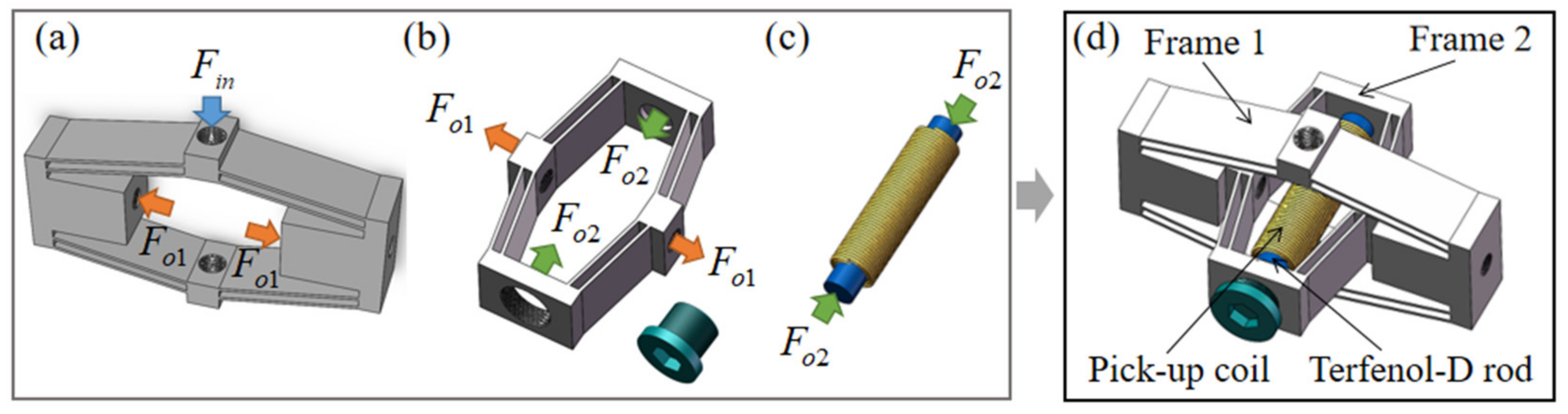
To this end, this paper designs a double-stage rhombus energy harvesting system based on Terfenol-D rods, which can harvest not only the vibration energy of the seats while the bus is moving, but also the pressure energy generated by the passengers. Considering the small vibration force of the seat, in order to fully improve the utilization of vibration energy, a double-stage rhombus amplification mechanism is used to drive the Terfenol-D rod to capture energy. The model of the double-stage rhombus amplification mechanism was designed in a limited physical space, and the Finite Element Analysis (FEA) studied the whole motion process of the mechanism and the characteristic parameters of the mechanism. The pre-magnetization layout for the optimal output performance of the harvesting device was studied and analyzed, and, finally, the output performance of the double-stage rhombus magnetostrictive energy harvesting system was carefully investigated and the sustained power generation capability of the fabricated prototype verified.
3. Model Analysis of Force Amplification Ratio of Double-Stage Rhombus Amplification Mechanism
In this section, a theoretical model of the force amplification ratio of a single rhombus frame is established, and the force amplification ratio of a double-stage rhombus amplification mechanism is analyzed by theoretical calculation. The theoretical model of amplification ratio can not only obtain the force amplification ratio and prove the feasibility of the amplification mechanism, but also provides a theoretical analysis model for the subsequent optimization of structural parameters. Analytical modeling of amplifying mechanisms based on the bridge-type beam is less common, and the specific theory is similar to the Euler-Bernoulli beam theory of Q. Xu et al. [
39], and the energy method of S. Wen et al. [
38]. Considering the bisymmetric characteristics of the rhombus frame in this paper, a quarter frame was selected for analysis in the modeling process, and the structural model of the bridge-type beam and the mechanical analysis model are shown in
Figure 6. Considering the bridge-type beam as an elastic beam and the other members as rigid bodies, the two-beam model can be simplified into an equivalent one-beam model AB. The initial force application plane is 1, the input force is
, the plane of one end of the output force is 2, and the output force is
, as shown in
Figure 6a. Considering that the side block has a certain influence on the force transmission, it is taken as the key force analysis object, as shown in
Figure 6d. The elastic direct influence amplification ratio of the frame material is considered, so this paper used Euler-Bernoulli beam theory [
30] and focused on the effect of deformation of the bridge-type beam on the transfer of the acting forces. Based on the analysis of the force amplification ratio of a single rhombus amplification frame, the expression of the theoretical description of the force amplification ratio with a double-stage rhombus amplification mechanism was, finally, derived.
First, a vertical upward force
is applied in plane 1, and the two-beam are simplified to a one-beam model, as in
Figure 6b, where the initial force is the
at the end point B of the bridge-type beam, which is amplified by the bridge-type beam to produce a horizontal output force
. Decompose
and
into
and
in the vertical beam direction and along the beam direction, as shown in
Figure 6c. According to the force analysis,
and
can be expressed as the following equation [
30]:
is the inclination angle of the beam with respect to the horizontal direction.
The force analysis of the simplified beam AB is carried out, and according to the balance of moments applied to beam AB, as shown in
Figure 6b, it is obtained that [
30]:
indicates the moment applied to the bridge-type beam, and are the vertical and horizontal dimensions of the bridge-type beam, and is the length of the bridge-type beam AB.
The moment
at endpoint B can be expressed as:
The deflection deformation of the bridge-type beam is shown in
Figure 6c, and the deformation of the beam is calculated according to Euler-Bernoulli beam theory as follows [
30]:
is the modulus of elasticity of the frame material, is the deflection of the bridge-type beam with respect to the neutral axis, is the moment of inertia of the area of the frame, and is the moment of inertia of the area of the beam.
According to
Figure 6c, it can be seen that there exists a fixed boundary of AB. Considering the limit value of AB, i.e.,
, the deflection of the bridge-type beam can be calculated by bringing Equation (4) into Equation (5) as follows [
38]:
Simplifying Equation (7) yields:
According to the moment balance of the side block, as shown in
Figure 6d, the horizontal deformation of the side block can be expressed as [
38]:
Area moment of inertia of the side block
:
The deformation of a bridge-type beam subjected to a tensile force
in the direction of the beam can be expressed as [
38]:
In the above equation, is the cross-sectional area of the bridge-beam material.
Similarly, since the output end of the rhombus frame remains rigidly connected to the end face of the Terfenol-D rod, the support reaction force generated at one end of the Terfenol-D rod is equal in magnitude to the force
acting at the output end of the rhombus frame. The deformation of the Terfenol-D rod in the axial direction can be expressed as:
In the above equation, and are the Young’s modulus and cross-sectional area of the Terfenol-D material, respectively.
According to the compatibility condition theorem, the total deformation in the horizontal X-direction is equal to zero, and the deformation relation can be obtained as follows [
30]:
Bringing Equations (1), (9), (11) and (12) into Equation (13) yields the equation:
The force amplification ratio is the ratio between the output force and the input force, i.e.,
. According to Equation (14), an equation containing
and
can be established, and by solving this equation an expression for the force amplification ratio of a single rhombus frame can be obtained as follows:
Considering the elastic deformation of the actual frame material, the loss of energy during the deformation of the bridge-type beam, and the tightness of the two frame screw connections, the efficiency of the input force transfer inevitably reduces, resulting in the force amplification ratio (
) of frame 1 and frame 2 not being equal to the force amplification ratio (
) of the double-stage rhombus amplification mechanism [
30]. Therefore, the transfer efficiency
is introduced, i.e., the ratio between the actual and theoretical Terfenol-D rod-branch reaction forces, and the energy lost is taken into account to finally derive the force amplification ratio of the double-stage rhombus amplification mechanism:


