Abstract
The rejection rate of tree stock in a forestry nursery can be as high as 35%. This is attributed to plant physiology, poorly trained seasonal workers and unsophisticated equipment. It is estimated that approximately 5% of seedling rejection in the pilot nursery (approximately 220,000 per year) is due to poorly dibbled holes. These holes are typically dibbled using a spiked wheel, which produces crooked and imprecise holes. The poor-quality holes cause bends in the stems, resulting in rejection. This article presents a tractor-drawn mechatronic dibbling machine that can produce precise vertical holes of a specified depth, spacing and diameter. Both hole quality and dibbling efficiency are greatly improved. The machine was tested at a nursery and produced 98% of the holes at the desired angle and 94% at the desired depth. The unwanted stem bends were eliminated with a subsequent reduction in rejects. Furthermore, it was found that worker productivity increased, as they did not have to spend time setting seedlings vertically.
1. Introduction
Productivity in agriculture has improved greatly over the years. The most significant developments in agriculture occurred during the 20th century with the introduction of the tractor. The Henry Ford and Son Corporation started mass production of Fordson tractors in 1917, made possible by their assembly-line techniques. A multitude of implements pulled and powered by tractors are developed to mechanize crop production in different steps, from tillage to harvesting [1]. Productivity has been increased further by the blending of sensors with machinery in many agricultural operations.
Despite this progress, many ‘in field’ operations remain highly labour-intensive, with labour contributing approximately 40% of operational costs in horticultural operations [2]. There is an increasing amount of research on introducing automation into the field and applying it at the point of harvesting; however, there is not yet a commercial solution for most crops. The continuing reliance on seasonal labour for most ‘in field’ tasks has many associated issues and needs to be addressed. Issues with seasonal labour include high costs and poor health and safety. These workers are usually undertrained; hence, the staff turnover rate is high, and the reliability of the staff is poor. In fact, it is difficult to secure the number of required staff. As a result, the efficiency and accuracy of quality control are poor.
The introduction of automation in the assembly line in factories greatly reduced the reliance on manual labour, improved efficiency and revolutionized the manufacturing industry. Although automation requires more costly equipment and highly trained staff, this cost is generally offset or overcome by the fewer staff required [3]. Automation works well in a factory environment, for example, in automobile production, where the tasks required are repetitive, parts are in fixed locations and have known sizes and the environment is controlled. It has taken some time for ‘smart’ machinery to transition from conventional factories into the agricultural environment due to the additional challenges associated with this type of environment, including:
- Difficulties handling organic produce where there is significant variation in size and shape of objects, as well as their location.
- Produce is delicate, highly sensitive to pressure and easily damaged.
- Dealing with an outdoor environment, for example, the weather, variable lighting conditions, dust and dirt.
- Required portability of equipment and distances over harsh terrain.
Forestry nurseries rely heavily on manual labour for many tasks, including taking and setting cuttings and lifting and grading tree stock. Managed forestry plantations are relatively juvenile in New Zealand. Land in New Zealand was mostly covered with native forests when European settlement began in the mid-nineteenth century; however, by 1913, rapid native deforestation was becoming unsustainable, threatening many native species with extinction. Since then, restrictions on harvesting native forests and conservation efforts have increased, prompting mass plantings of exotic species. In 2019, 99.7% of all lumber harvested was from plantation forests [4].
As such, forestry has grown to be a significant industry in New Zealand. It contributes approximately 1.6% of New Zealand’s GDP and directly employs approximately 25,000 people. Wood products are New Zealand’s third largest export earner, and commercial forestry covers approximately 6.4% of New Zealand’s land area. Furthermore, 45% of all lumber was exported in 2015 for a value of 4.8 billion NZD, the largest market being China, followed by Australia [4].
Radiata pine is by far the most widely grown species, constituting approximately 90% of New Zealand’s plantation forests. The next most popular species is Douglas fir at approximately 6%. The remaining forests are planted with eucalypts, cypress and other exotic species. It is estimated that commercial New Zealand forestry nurseries sold over 88 million seedlings in 2019, which equates to approximately 48,000 planted hectares [5].
New forests are propagated from cuttings or seedlings grown in a nursery, collectively known as tree stock. Seedlings are grown from seeds sown directly into the nursery beds, while cuttings are propagated from cuttings taken from mother plants. Tree stock is raised in nurseries, usually for one year, to ensure a healthy product and maximise the survival potential when planted out in the forest. A small portion of tree stock is raised in containers in greenhouses, but the vast majority is bare-root stock that is planted directly in prepared nursery beds, as pictured in Figure 1.
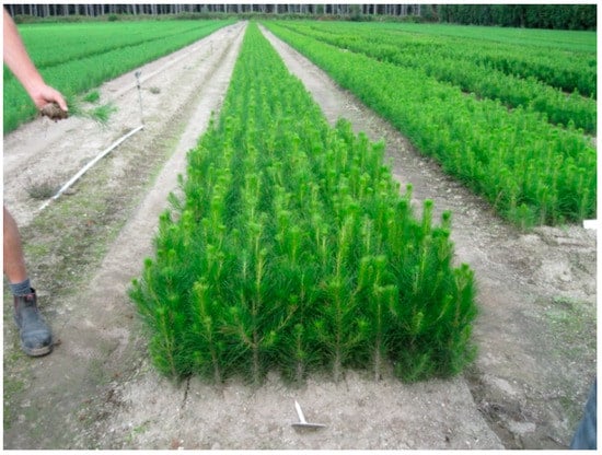
Figure 1.
Typical beds with Radiata pine seedlings at a forestry nursery in New Zealand.
Beds are raised slightly and spaced to allow room for tractor wheels. When first formed, they are approximately 150 mm high, but this varies over time due to the compaction and erosion of soil. Tree stock is densely packed in both directions: Trees are planted in eight rows at an inter-row spacing of 125 mm, and spaced at 70–120 mm along the length of the beds (intra-row spacing). Details of the layout of a nursery bed are pictured in Figure 2.
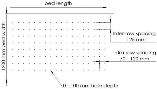
Figure 2.
A layout of nursery beds.
The process for raising both cuttings and seedlings starts differently, but once planted, subsequent processing is the same. Seedlings are sown directly into the nursery beds in spring [6] with a tractor-drawn drum seeder. Alternatively, cuttings approximately 100 mm in length are taken from mother plants in early to mid-winter [6] and set into precise holes in the nursery beds.
The process of forming holes in the nursery beds is called dibbling. In peak season, up to 120,000 seedlings will be planted per day, which each requires a straight vertical hole of a certain depth and spacing, depending on the seedling type. Holes for planting radiata pine cuttings are approximately 10 mm in diameter and 40 mm deep. One method used for dibbling is to manually punch the holes in the planting beds. Figure 3 (left) shows the punching tool, which is operated manually by two operators. There is extensive staff turnover, and because of this, workers are often undertrained. This can lead to inconsistency in dibbling in terms of the hole depth and spacing, as shown in Figure 3 (right). This method is also very slow.
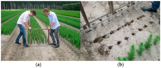
Figure 3.
Manual dibbling process. (a) Dibbling manually; (b) Manually dibbled holes.
Dibbling has been mechanized with basic implements to improve efficiency. The idea of using a rotating punch planter has been introduced for lettuce [7] and corn [8]. Tractor-drawn spiked wheels are typically favoured over manual labour for dibbling holes as they are much faster and less labour is required. A machine consisting of a set of spiked wheels is shown in Figure 4.
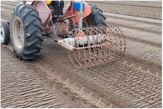
Figure 4.
A tractor-pulled dibbler with a set of spiked wheels.
However, the tractor-pulled dibbling machine is inadequate with respect to producing holes of acceptable quality. As the spiked wheels roll along the ground, holes are punched into the bed. The primary problem with this method is variation in the depth of the holes, non-round holes due to tearing and disruptions to the pesticide layer, as shown in Figure 5 (left). This is due to the motion of the wheels, which are pulled by the tractor as illustrated in Figure 5 (right). The trajectory of the pins forms a ‘torn’ hole with a tearing shape instead of a circular shape. The non-round holes lead to cuttings being planted non-perpendicular to the ground. This causes bends in the stem as they grow and results in rejection.
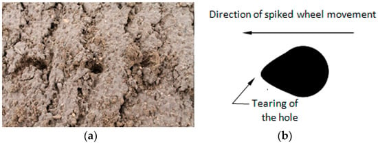
Figure 5.
Holes produced by a spiked wheel. (a) Hole appearance; (b) A non-round hole.
Dibbling is often used for seed planting and is often combined with an integrated seed-dropping mechanism. Typical applications include lettuce sowing [9,10,11], maize, redgram and cotton [12,13]. Performance increases have been achieved through mechanization of the process when compared to manual methods. For instance, an improvement in lettuce emergence with a pneumatic dibbler and seeder was observed when compared to a coulter drill [11]. Faster dibbling speeds have been shown, along with improved reliability of plant stands [10].
Besides purely mechanical devices such as spiked wheels, more advanced devices have been used. For example, a precision plug tray seeder driven pneumatically for sowing capsicum and tomato seeds has also been built [14,15]. The capacity of the seeder, depending on the tray size used, ranges between 38,000 and 60,000 cells/hr. Furthermore, a dibbler with four pneumatic cylinder heads was developed using a microprocessor control that offers greater opportunity for varying hole spacing to suit a range of crops [16]. It was found that 96% of the hole spacing for potatoes and 98% for onions were within the required ±10% specification. The flexibility and controllability highlight the advantages of using computer technology compared to purely mechanical systems [17].
Poorly dibbled holes often lead to tree stock with bent stems that are then rejected by the forestry industry. Dibbling has become a major problem that has resulted in an estimated 5% rejection rate of harvested seedlings (approximately 220,000 per year for a typical nursery), based on nursery statistics. This causes a significant revenue loss. An investigation of the dibbling process identified the following problems:
- Existing human dibbling methods are slow and unreliable.
- Current machine methods produce low-quality holes that lead to improperly planted seedlings.
- Lack of flexibility of existing methods with regard to hole size and spacing.
- Current methods compact the soil hindering root growth, so hole drilling is preferred.
- Currently, dibbling must be performed on the day of planting due to the deterioration of the bed surface.
As a result, dibbling is considered one of the major causes of inconsistent quality. In order to reduce cost and raise productivity, a smart mechanized process is required to dibble the holes for the cuttings in the field. Over 2 million high-precision holes need to be drilled per season, and they must be vertical. Achieving this in a dynamic environment while the tractor is moving is far more challenging when compared to typical applications where trays are dibbled in controlled greenhouse environments. This article describes the development and evaluation of a mechatronic dibbler to drill high-precision holes for planting cuttings outdoors in a forestry nursery.
2. The Dibbler
A dibbler is developed based on pneumatics, which is configurable to varying depths, spacing and diameters for different tree types [18]. The major components of the dibbler are shown in Figure 6.
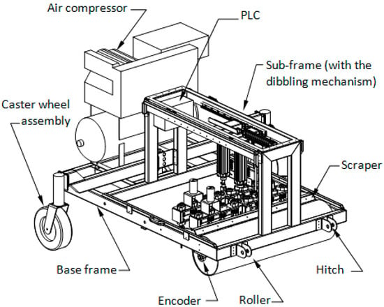
Figure 6.
The dibbler components.
It consists of a base frame with hitch points, which can be attached to a tractor. The track width of the dibbler is 1800 mm to match the spacing of the nursery beds, and it is approximately 2000 m long. A roller is installed in the front of the frame to level the machine relative to the nursery bed. This ensures consistent hole depths across the width of the bed. The rear axle has a central pivot to allow the roller to sit flat on the surface of the bed. An encoder is attached to the roller so that the distance travelled by the machine, and hence, the velocity can be measured. The roller also slightly compresses the soil before dibbling to ensure the flatness of the bed, and therefore improve the consistency of the depth of the holes. The pressure from the roller depends upon its diameter. A large-diameter roller implies greater mass, so higher pressure acts on the soil. However, the pressure can be high even with a smaller roller since its contact area is comparatively smaller.
Figure 7 shows a free-body diagram of the roller. The dibbler body is greyed out to show how its force F acts on the roller.
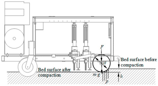
Figure 7.
Free body diagram of the roller.
The pressure from the roller on the bed surface can be approximated as
where is the force acting on the roller due to the dibbler body;
is the mass of the roller which is a function of roller diameter ;
is the gravitational acceleration;
is the roller length;
is the soil compaction such that .
The roller mass depends upon the internal structure of the roller. It is obtained by experimentally measuring the roller mass m with various diameters as plotted in Figure 8a. Figure 8b plots the pressure acting on the bed surface against the roller diameter d. It can be seen that the pressure tends to be constant as the diameter exceeds a specific value. The roller diameter can be determined based on the balance between the roller mass and pressure so that a light enough roller is used to exert a small and steady pressure on the bed surface.
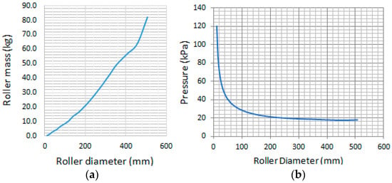
Figure 8.
Plots of roller mass and pressure vs. roller diameter. (a) Roller mass m vs. roller diameter d; (b) pressure p vs. roller diameter d.
A scraper is equipped to clear the excess soil off the roller. This prevents soil build-up on the roller, which would increase the roller diameter, and thereby affect the distance and speed calculations. The dibbler is towed by the tractor and passively follows the path taken by the tractor using two rear caster wheel assemblies. The dibbling sequences are controlled by an Allen–Bradley Micro830 [19,20] Programmable Logic Controller (PLC), which is mounted in a waterproof enclosure on the sub-frame.
The dibbling mechanism is fixed on a sub-frame with the pivoted axle at the centre of the base frame so that it allows the mechanism to self-level across the bed width. An air compressor is attached to the rear part of the base frame, which provides compressed air to drive the dibbling mechanism pneumatically. Positioning the compressor in this way means more weight is transferred to the rear wheels, rather than the roller, to prevent overcompression of the bed. Figure 9 depicts the details of the dibbling mechanism.
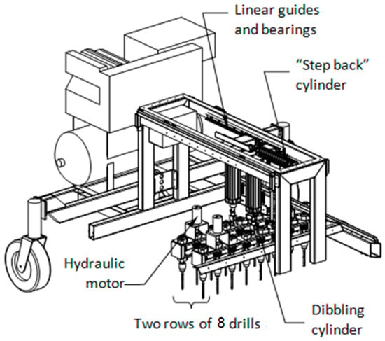
Figure 9.
The dibbling mechanism (part of the base frame is hidden for clarity).
Drilling is preferable to dibble a hole than punching, as punching compresses the soil and inhibits root growth. Two rows are dibbled simultaneously to allow a realistic dibbling speed. The dibbling mechanism consists of two rows of eight drills. Each row is driven by a hydraulic motor, using a chain drive system to distribute power to adjacent drills within the same row. The rotational speed of the motor is controlled by a flow controller.
The drilling action is actuated by two pneumatic dibbling cylinders (one for each row), which yields the vertical up and down motion. The dibbling action is started when the machine has travelled the correct distance, which is determined by the encoder attached to the roller. To control the depth of dibbling, a plunger is attached to each dibbling row, which senses when the drilling assembly reaches the required depth. The plunger can be raised and lowered to adjust the dibbling depth. This provides partial cylinder stroke and minimises air consumption. The drilling rows are connected by a threaded rod. The operator winds a handle to adjust the distance between rows. A potentiometer is used to measure the distance between the rows.
The dibbler is towed continuously at a fixed speed by the tractor. A controlled step-back motion is needed to ensure the dibbling bits are not moving relative to the ground while dibbling. Without this step-back motion, the dibbling bits would be dragged through the soil, causing an elongated hole similar in shape to the spiked wheel. The step-back cylinder has speed control and is connected to the dibbling mechanism, which slides on a pair of linear guides and bearings installed on the top of the sub-frame. The step-back speed is synchronized to the instantaneous forward speed of the tractor; however, it operates in the opposite direction to ensure no relative movement between the dibbling bits and the ground during dibbling.
The dibbling process is event-based, which can be summarised as follows:
- Count pulses from the encoder, and once the dibbler has moved the desired spacing, turn on dibbling cylinders.
- Supply compressed air flow to:
- Step-back cylinder based on the speed of the dibbler so that the speeds are always opposite in direction and equal in magnitude. Continuously update this.
- Dibbling cylinders to drive the drills to the required depth, and then retract them to the bed surface.
- Return the dibbling and step-back cylinders to their home position.
- Repeat steps 1 to 4.
A dibbling cycle performed by the dibbler pulled by a tractor moving at a velocity v is depicted in Figure 10. The drill is at its home position at the beginning of the cycle (t = 0), which is at a clearance of c above the bed surface. The drill is on the bed surface at time t1 and a hole of depth h is drilled with feed rate at time t2. The drill is retracted to the bed surface at time t3.
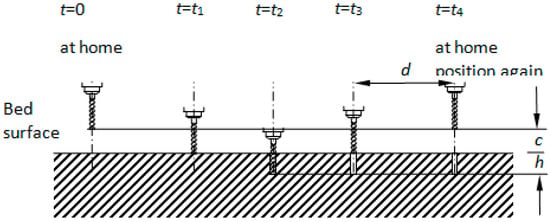
Figure 10.
A dibbling cycle.
Within this period (t = 0 to t = t3), the step-back cylinder extends with velocity v so that the drills driven by the dibbling cylinders are operated vertically. Then all the cylinders are retracted to their home positions at time t4 so that the dibbling cycle starts again at the next row with the intra-row distance d.
Time , , and are given by
Time is termed as the dibbling cycle time.
Hence, the stroke velocities of the dibbling cylinders and step-back cylinder (relative to the cylinders) are expressed as
There are three pneumatic cylinders in the dibbler: Two dibbling cylinders for the vertical motion of the drills to dibble the hole and one for the step back movement. The strokes of dibbling cylinder and step-back cylinder are
The flow of compressed air into the dibbling cylinder is controlled by a solenoid-spring valve. The step-back cylinder needs to have speed control as its function is to cancel the forward motion of the tractor. The flow of compressed air is determined by an electronic flow control valve. The pneumatic schematic of the dibbler is illustrated in Figure 11.
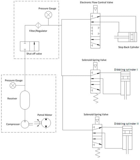
Figure 11.
The pneumatic schematic of the dibbler.
The following is the basic sequence the electronics follows when there is power supplied to the system. The cycle repeats itself at a rate of thousands of hertz.
- Read inputs—these are sensor signals including cylinder piston position switches, encoder pulse count, and potentiometer value for intra-row spacing.
- Execute the following:
- Update timers/counters/speed, etc., based on inputs.
- Check for an error condition, if any.
- Determine dibbling mode including error, idle, down stroke, upstroke, and return stroke.
- Check if anything needs to be performed (i.e., update outputs—solenoid position, step back speed, error lights).
- Write outputs—send signals to valves or error lights as determined by the code.
Programming was performed in the Connected Components Workbench (CCW) software suite (Rockwell Automation 2020b). Coding was written in Structured Text format, and the program can be downloaded to the PLC using a USB cable. The PLC I/O is shown in Figure 12.
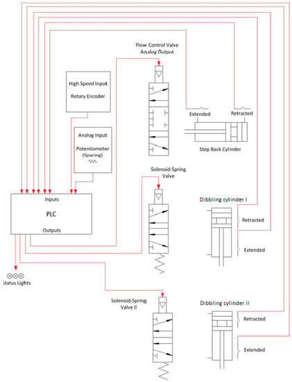
Figure 12.
The PLC I/O.
3. Field Test and Evaluation
The dibbler is tested on site in Tokoroa, New Zealand (Supplementary Materials). The nursery mainly produces radiata pine seedlings and cuttings. The nursery experiences a high rejection rate due to poorly dibbled holes. The dibbler is pulled behind the Kubota MX9540 tractor at a constant creep speed of approximately 0.42 km/h as shown in Figure 13a. At this speed, 120,000 holes for radiata pine are dibbled in just over 2½ hours (approximately 165 min) at a hole spacing of 77 mm. This is a rate of approximately 12 holes dibbled per second. The dimensions of the hole are 10 mm in diameter and 40 mm in depth. The dibbled bed is shown in Figure 13b.
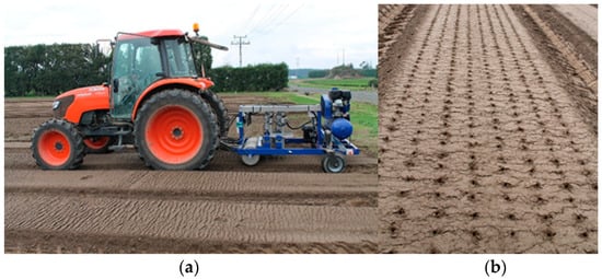
Figure 13.
Dibbler field tests. (a) The dibbler and the tractor. (b) Planting bed with holes dibbled.
The dibbler operation is as follows:
- Check the hole depth and spacing. Adjust these hole parameters if necessary.
- Attach the dibbler to the tractor using the hitch.
- Lift the dibbler and transport to the bed.
- Lower the hitch so that the dibbler rests on the bed.
- Start the air compressor and turn on power to the dibbler.
- Drive the tractor along the bed to perform the automatic dibbling cycle:
- The roller wheel sets the bed height and the encoder spins. Once the desired spacing is achieved, turn on dibbling cylinders. Supply air flow to the step-back cylinder based on the dibbler (tractor) speed.
- Wait until the dibbling cylinders extend to the end of the stroke to perform the dibbling.
- Wait until the dibbling cylinders and the step-back cylinder retract.
- The dibbler will be suspended if it is in error. Errors include the dibbler moving too fast, time out, and step back at end of stroke. Push the button to reset.
- Wait until the dibbler has moved the desired distance then start the dibbling cycle again.
- At the end of the row, turn off the dibbler. Raise the hitch and move to the next bed.
To compare the hole quality dibbled by the dibbler and the spiked wheel, a simple measuring system is built that comprises a rod 10mm in diameter, a protractor for measuring hole angle and a ruler for measuring hole depth as shown in Figure 14. The scales of the measuring system can be read to ±1 mm and ±0.5°. The rod inserted into a hole dibbled by a spiked wheel is shown in Figure 14a while Figure 14b shows the rod inside a hole dibbled by the dibbler. The elongated hole caused by tearing of the spike as it rotates results in a large angle, well in excess of the 3° maximum angle preferred by the nursery.
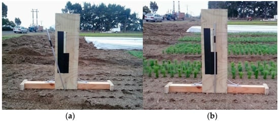
Figure 14.
Comparing the hole depth and angle of (a) a hole dibbled by a spiked wheel and (b) a hole dibbled by the dibbler.
The measuring system is also used to determine the consistency of the depth and angle of a sample of 100 holes.
4. Results and Discussion
The dibbling cycle time can be expressed as
The dibbler has two rows of drills, hence
This implies that the tractor velocity is dependent upon the dibbling feed rate (or the stroke speed of the dibbling cylinder). Let L be the length of the bed, while the number of rows n is
where ⌊ ⌋ is the floor function.
The total time T to complete n rows of holes in a bed is
Rearranging the terms yields
Under the condition that
which implies the dibbled holes are deep or the clearance is very small compared to the hole depth. Furthermore,
The total time to complete the task is approximated as
or
which is the total time of dibbling 2n rows of holes.
Therefore, the total time T is dependent upon the clearance s and stroke velocity of the dibbling cylinder. The effect of clearance c is small if it is small compared to the hole depth h (c << h). However, if the stroke velocity is fast, then the total time T can be greatly reduced.
The field test values and the experimental values of the tractor velocity v and total time to complete the task are listed in Table 1.

Table 1.
Comparison between experimental and calculated values.
The results of the 100 sample holes are shown in Figure 15. The dotted box indicates the range of desired measurements as determined by the nursery, i.e., a depth of 40 ± 5 mm and an angle of 0 ± 3°. The average hole depth was 39.7 mm with an angle of 1.3° and standard deviations of 3.3 mm and 1.1°, respectively. In the trial of 100 holes, the dibbler achieved 94% of holes within the ±5 mm tolerance. Moreover, 98 % of holes are within the desired angle of ±3°.
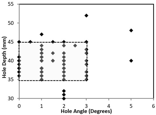
Figure 15.
Depth of hole vs. angle from vertical.
The basic requirement as set by the nursery is that the holes for radiata pine are 40 mm ± 5 mm deep and ±3° angle from vertical. Although many of the measurements had the same value due to the lack of resolution of the measurement method, the vast majority of the holes are within these ranges. This is a good result considering the non-perfect surface of the planting bed. It is very difficult for an automated machine to compensate for all 16 drilling points without having independent assemblies for each dibbling bit. The accuracy of the depths of the holes is attributed to the design of the dibbler. The roller successfully aligned the dibbler across the width of the bed. Additionally, the roller slightly compacted the soil to smooth out minor unevenness on the surface. Slight inaccuracies in the angle in the holes can be attributed to the dibbler not being perfectly level relative to the length of the bed. The caster wheels run in tracks adjacent to the raised nursery bed, which are not consistent in depth. This changes over time due to erosion and compaction of the surface due to multiple passes of the tractor. It is difficult to passively account for this without some form of an active levelling system. Furthermore, it is found that the uneven surface of the planting bed will undoubtedly cause the dibbler to have varying hole depths and angles as the depth sensors are located in only one place on the bed whereas there are 16 holes each in different places. It is highly unlikely that the level of the bed would be the same at all 16 points. By observation, it is estimated that the ±5 mm hole depth can be attributed to the uneven surface.
Figure 16a shows five cuttings in holes made by the spiked wheel dibbler. It can be seen that the ‘torn’ hole causes non-vertical seedlings. These then have to be manually set to the vertical position otherwise the plants will be rejected during harvesting. It can also be seen that the surface of the planting bed is very disturbed due to the tearing effect of the spikes. Figure 16b shows another five cuttings placed in holes made by the dibbler. It can be seen that all the cuttings are vertical and of even height. It is clear that the spiked wheel produces very poor-quality holes.

Figure 16.
Cuttings placed in the dibbled holes. (a) Holes dibbled by the spiked wheel. (b) Holes dibbled by the dibbler.
The nursery managers decided that all holes produced by the dibbler, including those outside their original specification, are suitable for planting, as shown in Figure 17. It can be seen that the holes shown in Figure 17a are evenly distributed on the bed after dibbling and the workers are inserting the cuttings into the holes for production as pictured in Figure 17b.
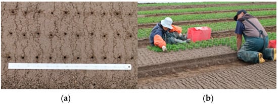
Figure 17.
Outcomes of the dibbler field test. (a) Holes dibbled by the dibbler. (b) Inserting the cuttings into the holes.
The quality of the holes created by the spiked wheel is predetermined and limited by the geometry of the wheel and the pins. Figure 18 shows the path taken by the pins as the spiked wheel rotates and the holes are dibbled. It is clear that this method will result in an elongated hole, which is much larger than the 10 mm diameter desired.
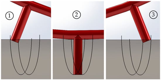
Figure 18.
Path taken by the pins in the spiked wheel during a dibbling cycle. Entry position ①, full depth position ② and exit position ③.
Through geometry, the length of the groove created by the spiked wheel can be determined. The distance between the entry point of the pin relating to position 1 and the contact point of the wheel on the ground is given by x, as pictured in Figure 19.
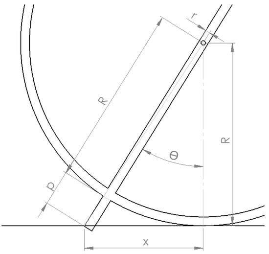
Figure 19.
Geometry of spiked wheel at position 1.
x is given by
where p is the length of the pin, R is the radius of the wheel and r is the radius of the pin.
In the time taken to reach position 2, the wheel had moved forward by R. The pins entry and exit paths are symmetrical. Therefore, the length of the groove, l, is given by
Figure 20 shows how the length of the groove changes with the wheel radius. The spiked wheel used by the nursery is approximately 500 mm in diameter, therefore the groove length for this situation will be approximately 30 mm long, instead of the desired 10 mm diameter hole. The best case that can be achieved with the spiked wheel design, without impractically increasing the size of the wheel, would be a groove length of approximately 20 mm.
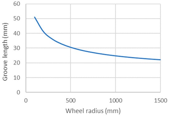
Figure 20.
Plot of groove length vs. wheel radius for a 40 mm long, 10 mm diameter pin.
Although the dibbler outperforms the spiked wheel in terms of precision, it is slower in operation, therefore additional labour and equipment costs will be incurred with the dibbler. The dibbler takes approximately 2 h longer than the spiked wheel to produce 120,000 holes. For 2.2 million holes per annum, this equates to an additional annual expense of approximately 4800 NZD, assuming labour of 30 NZD per hour and tractor expenses of 100 NZD per hour. However, the dibbler becomes cost-effective assuming that it can reduce the number of rejected trees. Trees retail for approximately 0.65 NZD each, a potential saving of 143,000 NZD considering the estimated rejection of 220,000 trees per annum.
5. Conclusions
A piece of agricultural machinery for dibbling holes in a forestry nursery was developed. It was built based on pneumatics and mechatronics. The dibbler was tested in a nursery with good performance. The dibbled holes can be configurable to varying depths, spacing and diameters for different tree types as required by the nursery. The machine is fully commissioned and has been used successfully for eight seasons, dibbling approximately 20 million holes during this period.
As holes dibbled are now of higher quality, the rejection rate of trees is expected to drop significantly. Additionally, the productivity of the workers setting the cuttings and seedlings in the holes has increased as the holes are better formed and easier to work with. The time to set the trees is estimated to have been reduced by approximately one-third. As a result, the dibbler has benefited the nursery in three main ways:
- Improved yields due to the lower rejection rate.
- Cost savings.
- Estimated increase in productivity while setting trees of 30%.
The dibbler highlighted the potential for increased productivity by introducing more advanced equipment into the nursery.
Supplementary Materials
The following supporting information can be downloaded at: https://www.mdpi.com/article/10.3390/machines10090790/s1, Video S1: Dibbler field test.
Author Contributions
Conceptualization, B.M. and M.D.; methodology, B.M.; software, B.M.; resources, M.D.; writing—original draft preparation, C.K.A.; writing—review and editing, S.H.L.; supervision, M.D.; project administration, M.D. All authors have read and agreed to the published version of the manuscript.
Funding
This research received no external funding.
Data Availability Statement
Not applicable.
Conflicts of Interest
The authors declare no conflict of interest.
References
- Edan, Y.; Han, S.; Kondo, N. Automation in Agriculture; Springer: Berlin/Heidelberg, Germany, 2009; pp. 1095–1128. [Google Scholar]
- Bechar, A.; Eben-Chaime, M. Hand-held computers to increase accuracy and productivity in agricultural work study. Int. J. Product. Perform. Manag. 2014, 63, 194–208. [Google Scholar] [CrossRef]
- Bechar, A.; Vigneault, C. Agricultural robots for field operations: Concepts and components. Biosyst. Eng. 2016, 149, 94–111. [Google Scholar] [CrossRef]
- Forest Owners Association. Facts & Figures 2019/20 New Zealand Plantation Forest Industry. Report. 2020. Available online: https://www.nzfoa.org.nz/images/Facts_Figures_2019_20_Web_FA3-updated.pdf (accessed on 22 July 2022).
- Ministry for Primary Industries. Provisional Estimates of Tree Stock Sales and Forest Planting in 2016. 2019. Available online: https://uploads-ssl.webflow.com/5d4797a2a904cdf4df041fd6/5f6a89eca31d3750f6f77d37_2019-Provisional-estimates-report-tree-stock-sales.pdf (accessed on 5 May 2021).
- Menzies, M.I.; Holden, D.G.; Klomp, B.K. Recent trends in nursery practice in New Zealand. New For. 2001, 22, 3–17. [Google Scholar] [CrossRef]
- Wilkins, D.E.; Adrian, P.A.; Conley, W.J. Punch-planting vegetable seeds. Trans. ASAE 1979, 22, 746–749. [Google Scholar] [CrossRef]
- Molin, J.P.; Bashford, L.; Bargen, K.V.; Leviticus, L.I. Design and evaluation of a punch planter for no-till systems, March. Trans. ASAE 1998, 41, 307–314. [Google Scholar] [CrossRef]
- Finch-Savage, E.W.; Rayment, M.; Brown, F.R. The combined effects of a newly designed dibber drill, irrigation and seed covering treatments on lettuce and calabrese establishment. Ann. Appl. Biol. 1991, 118, 453–460. [Google Scholar] [CrossRef]
- Brown, F.R.; Miles, S.J.; Butler, J. Design and development of a high-speed dibber drill for improved crop establishment. J. Agric. Eng. Res. 1994, 58, 261–270. [Google Scholar] [CrossRef]
- Miles, S.J.; Reed, J.N. Dibber Drill for Precise Placement of Seed and Granular Pesticide. J. Agric. Eng. Res. 1991, 74, 127–133. [Google Scholar] [CrossRef]
- Jayan, P.R.; Kumar, V.J.F. Evaluation of a dibber wheel at different selected parameters under static conditions. J. Inst. Eng. Agric. Eng. Div. 2006, 87, 12–15. [Google Scholar]
- Jayan, P.R.; Kumar, V.J.F. A mechanical dibber planter for selected seeds, Agricultural Mechanization in Asia. Afr. Lat. Am. 2010, 41, 75–82. [Google Scholar]
- Gaikwad, B.B.; Sirohi, N.P.S. Design of a low-cost pneumatic seeder for nursery plug trays. Biosyst. Eng. 2007, 99, 322–329. [Google Scholar] [CrossRef]
- Rathinakumari, A.C.; Kumaran, G.S.; Mandhar, S.C. Design and development of tray type vacuum seeder and tray type dibbler for vegetable nursery. J. Appl. Hortic. 2005, 7, 49–51. [Google Scholar] [CrossRef]
- Lawrence, M.J.; Buckmaster, D.R.; Lamont, W.J., Jr. A pneumatic dibbling machine for plastic mulch. Appl. Eng. Agric. 2007, 23, 419–424. [Google Scholar] [CrossRef]
- Gray, D.; Steckel, J.R.A.; Miles, S.; Reed, J.; Hiron, R.W.P. Improving seedling establishment by a dibber drill. J. Hortic. Sci. 1995, 70, 517–528. [Google Scholar] [CrossRef]
- Duke, M.; McGuinness, B.; Kunnemeyer, R. Development of a robotic dibbling machine for improving the quality of forestry seedlings. In International Symposium ISB-INMA-TEH Agricultural and Mechanical Engineering; Vladut, V., Vasilica, S., Eds.; publisher: Bucharest, Rumania, 2015. [Google Scholar]
- Rockwell Automation (a). 2020. Retrieved June 26, 2021. Available online: https://www.rockwellautomation.com/en-nz/products/hardware/allen-bradley/programmable-controllers/micro-controllers/micro800-family/micro830-controllers.html (accessed on 22 April 2020).
- Rockwell Automation (b). 2020. Retrieved June 26, 2021. Available online: https://www.rockwellautomation.com/en-nz/capabilities/industrial-automation-control/design-and-configuration-software.html (accessed on 22 April 2020).
Publisher’s Note: MDPI stays neutral with regard to jurisdictional claims in published maps and institutional affiliations. |
© 2022 by the authors. Licensee MDPI, Basel, Switzerland. This article is an open access article distributed under the terms and conditions of the Creative Commons Attribution (CC BY) license (https://creativecommons.org/licenses/by/4.0/).