Abstract
The operating condition and structural state of the converter transformer are closely related to vibration. Abundant harmonics aggravate the vibration of windings and iron cores, resulting in frequent mechanical structural failures, which seriously affect the stable operation of the power system. Traditional research mainly focuses on the vibration of AC transformers without harmonics and there is no in-depth discussion of the vibration mechanism and the numerical calculation model of windings and iron cores under harmonics. In addition, the influence of harmonics, winding connection method and other factors on the vibration characteristics are not clear. Therefore, this paper analyzes the voltage and current harmonic components and contents, establishes a harmonic-vibration numerical model and compares the vibration time-frequency characteristics with or without harmonics and different valve side winding connections through vibration measurement experiments. Finally, a combined simulation analysis reveals the contribution of the windings and core to the tank. The results show that the tank vibration amplitude and dominant frequency will increase under harmonica and the valve side current will affect the dominant frequency. Among these results, when there are harmonics, the amplitude increases by three times, the vibration dominant frequency changes from 100 Hz to 400 Hz and the frequency spectrum widens to 2000 Hz. In particular, the contribution of the winding vibration under the harmonic current will exceed the iron core. The research results reveal the influence of converter transformer harmonics on vibration, which can provide a theoretical basis for numerical calculation of vibration and monitoring of operating conditions and guide the design of structural vibration reduction to reduce mechanical failures caused by vibration.
1. Introduction
The vibration signal can reflect well the internal mechanical structure of the converter transformer. During operation, tank vibration is mainly caused by the electromagnetic force between the winding and the magnetostrictive force of the iron core. In particular, affected by the switching devices in the converter valve, there are abundant harmonic components in the voltage and load current, resulting in abnormal vibration of the iron core and windings, loose windings, cracking of iron core clips, and other problems, which seriously affect operational safety and the noise accompanying the vibration also seriously affects the environment of the converter station [1,2,3,4]. Therefore, it is urgent to establish a numerical model of the vibration under harmonics and combine this with the experimental measurement data to reveal the vibration characteristics of the converter transformer under operating harmonic conditions.
Tank vibration in operation is mainly composed of winding vibration and iron core vibration. Generally, it is considered that the winding vibration amplitude is proportional to the square of the current, the vibration amplitude of the iron core is proportional to the square of the voltage and the dominant frequency of the vibration is twice the frequency of the power supply. At this time, the dominant frequency of vibration is 100 Hz under the action of 50 Hz sinusoidal excitation of winding and iron core [5,6]. The vibration signal of the external tank can effectively reflect the mechanical changes in the internal structure. When the structure or the force changes, the tank vibration response will also change accordingly. Therefore, by monitoring the vibration changes on the surface of the tank, fault diagnosis and identification can be carried out. At present, the influence of harmonics on the vibration and the vibration fault identification technology are still in the development stage. Refs. [7,8,9] analyzed the harmonic components of the three-phase AC transformer and found that the third harmonic and the fifth harmonic are more and the vibration is much larger than that without harmonics. The conclusion proves that the harmonics can increase the amplitude and damage the mechanical structure. Refs. [10,11] found that the converter transformer current contains the fifth harmonic and the seventh harmonic and established a simulation model considering the harmonics. It is proved that the current harmonics will change the distribution of the leakage magnetic field in the space around the winding, thus affecting the winding vibration. In refs. [12,13,14], through the vibration measurement test, it is found that the DC bias will increase the core vibration amplitude and affect the operation stability, corresponding suggestions are put forward in conclusion to reduce the influence of the DC bias. Refs. [15,16,17,18] found that the current in a DC system is rich in high-frequency harmonics; for this reason, an inductive filter is designed to reduce the winding vibration and noise. References [19,20] measured the vibration under sinusoidal voltage and sinusoidal current, extracted the time-frequency and energy characteristic parameters from multiple angles and proposed a vibration fault identification model. In addition, refs. [21,22] extracted multi-sensor vibration characteristic parameters, constructed vibration characteristic images based on deep learning methods and realized transformer fault diagnosis.
To sum up, abundant current harmonics will aggravate the vibration of the converter transformer. At present, a large number of references have established vibration models of windings and iron cores under sinusoidal excitation (no harmonics), extracted vibration characteristic parameters under different working conditions and then combined deep learning algorithms and data processing methods to realize state identification and fault diagnosis. We know that the numerical model and data characteristics are the important basis for fault diagnosis using vibration identification technology. However, for converter transformers, the structure and operating environment are different, so the vibration characteristics are quite different from those of AC transformers. Moreover, the relationship between the winding and the core vibration and harmonics has not been fully deduced yet and there is also a lack of corresponding measured data to analyze the influencing factors. Therefore, it is difficult to accurately describe the vibration mechanism and mechanical structure state under harmonics.
Therefore, this paper analyzes the harmonic content of voltage and current in actual working conditions. Starting from electromagnetic theory, the mathematical models of winding electromagnetic vibration and iron core magnetostriction vibration are established. Based on the vibration test platform, the measurement test and simulation data were obtained, the vibration characteristics of different winding types were compared and the correlation law between current harmonics and vibration was revealed. The research results can comprehensively elucidate the vibration state under the action of harmonics.
2. Structure and Operating Environment
2.1. Structural Composition and Operating Parameters
The converter transformer in this paper is a single-phase double-winding type, the external structure is mainly composed of grid side inlet bushing, valve side outlet bushing, shell, oil pump and cooling fan and the internal structure is mainly composed of the iron core, winding and on-load tap-changer, as shown in Figure 1.
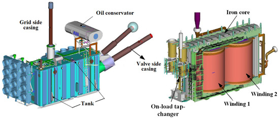
Figure 1.
The internal and external components of the converter transformer [23].
2.2. Types of Converter Transformers
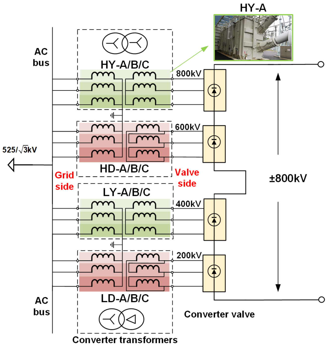
The ±800 kV HVDC transmission project adopts a (400 + 400) kV double 12-pulse bipolar system and the corresponding converter transformers in pole 1 and pole 2 are connected in the same way and arranged symmetrically. Figure 2 shows the connection mode of the converter transformer in pole 1 of the DC system.

Figure 2.
The connection mode of 12 converter transformers in pole 1.
There are 12 converters in pole 1 with the same structure and technical parameters, as shown in Table 1. Since the deflection angle of 30 degrees is to be provided for the converter valve, the valve-side windings of the three transformers will form a Y-type and D-type connection. In addition, the DC voltages of the valve side bushings are 200 kV, 400 kV, 600 kV and 800 kV, respectively. According to the voltage level, the high end (H) > 400 kV and the low end (L) 400 kV. Therefore, the 12 converter transformers are numbered as HY/HD/LY/LD-A/B/C.

Table 1.
±800 kV Converter transformer parameters.
It can be seen from Figure 2 that the grid side voltages are the same, but the valve side voltages are different and contain more harmonics. However, all grid side currents are the same and the valve side current is different under different connection methods for the valve side outlet, . In addition, the output load is non-linear and the grid-side and valve-side currents also contain many harmonics.
In this paper, the voltage and current data of 12 converter transformers are collected from the real-time wave recording software in the control room of the converter station for analysis.
2.3. Grid Side and Valve Side Voltage
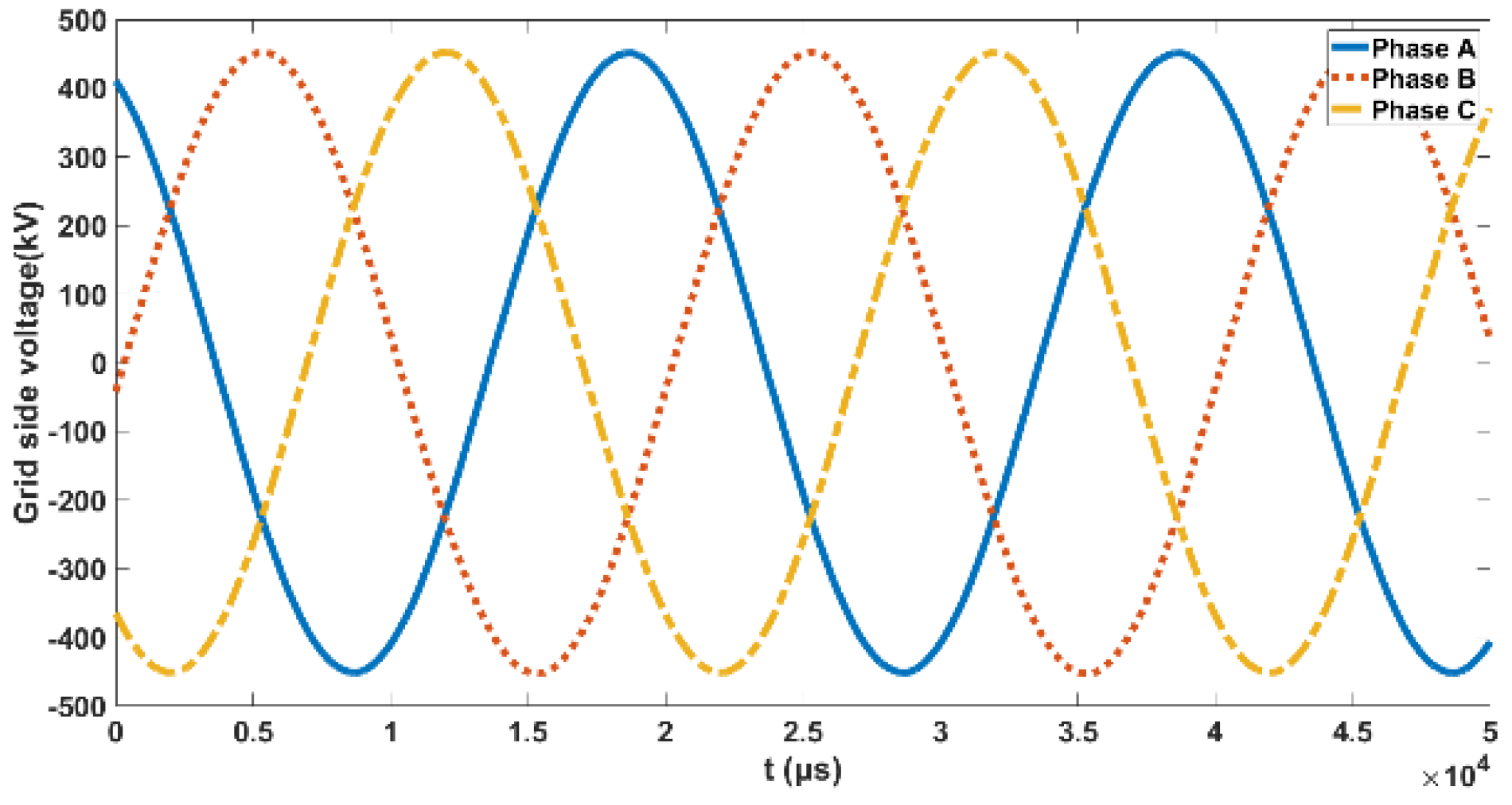
The grid side (AC side) voltage of the converter transformers under different types is the same. The grid-side voltage is a standard sine wave with almost no harmonic components, as shown in Figure 3.
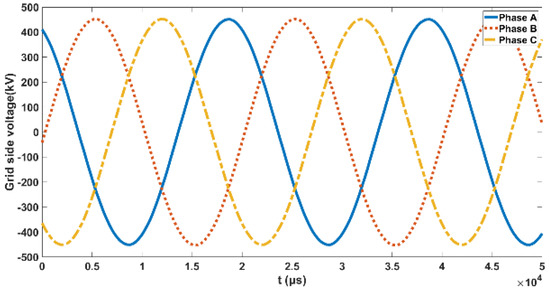
Figure 3.
The grid−side voltage.
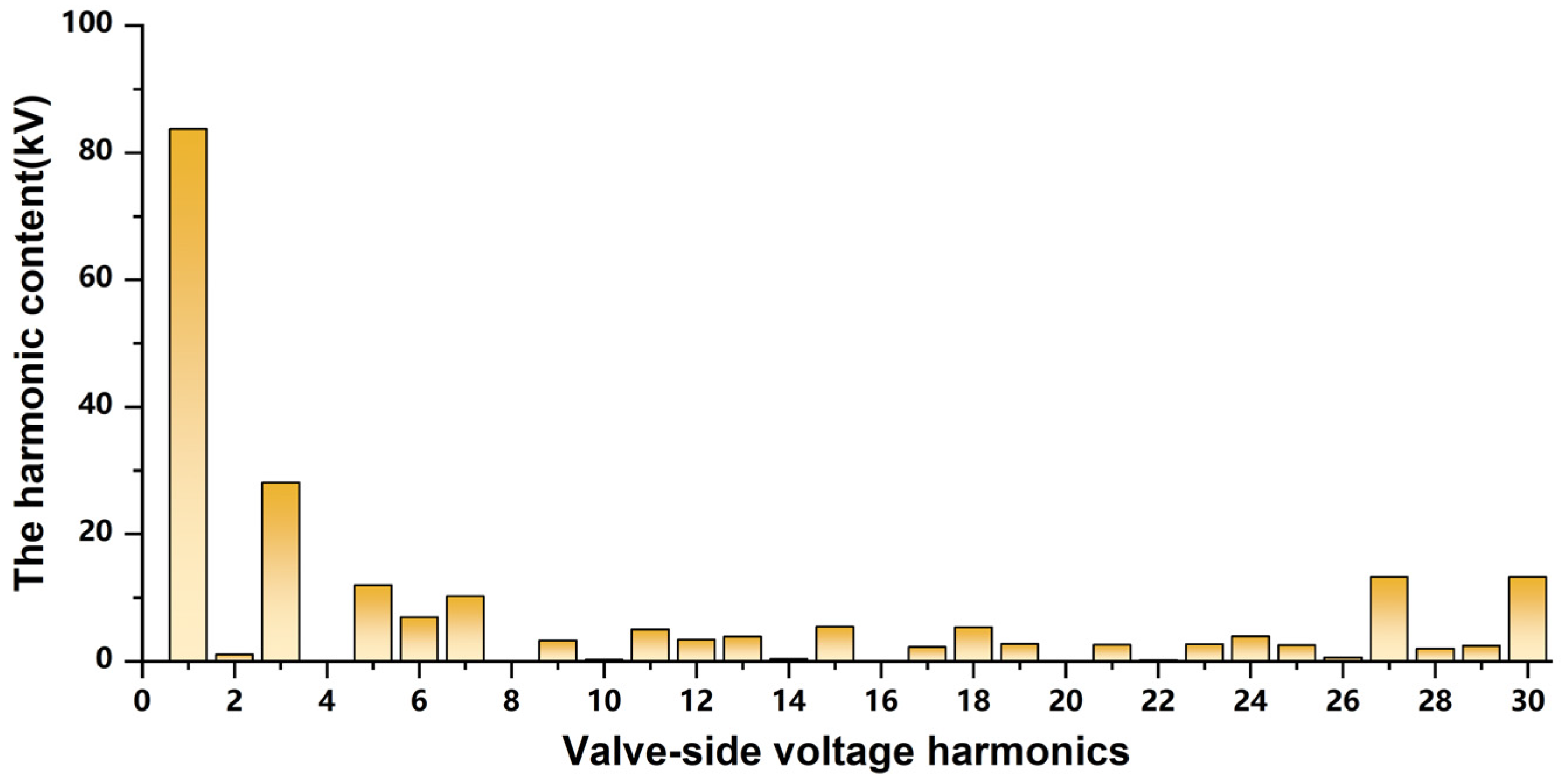
The outlet end of the valve side winding is connected to the converter valve and the induced voltage on the valve side is seriously distorted in Figure 4. The specific harmonic components and contents in the voltage are shown in Figure 5.
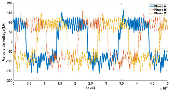
Figure 4.
The valve−side voltage.

Figure 5.
Harmonic components in valve side voltage.
In addition to the fundamental wave, the valve side voltage is rich in odd and even harmonic components. Odd harmonics are 4k ± 1, even harmonics are 6k and k is an integer. The components and contents of voltage harmonics are shown in Table 2.
Table 2.
Odd and even harmonic content in valve side voltage.
The valve side voltage has many harmonics, mainly because the valve side outlet terminal is connected with power electronic devices such as converter valves, and the trigger angle will be delayed during commutation, resulting in nonlinear load impedance characteristics.
2.4. Grid-Side and Valve-Side Current
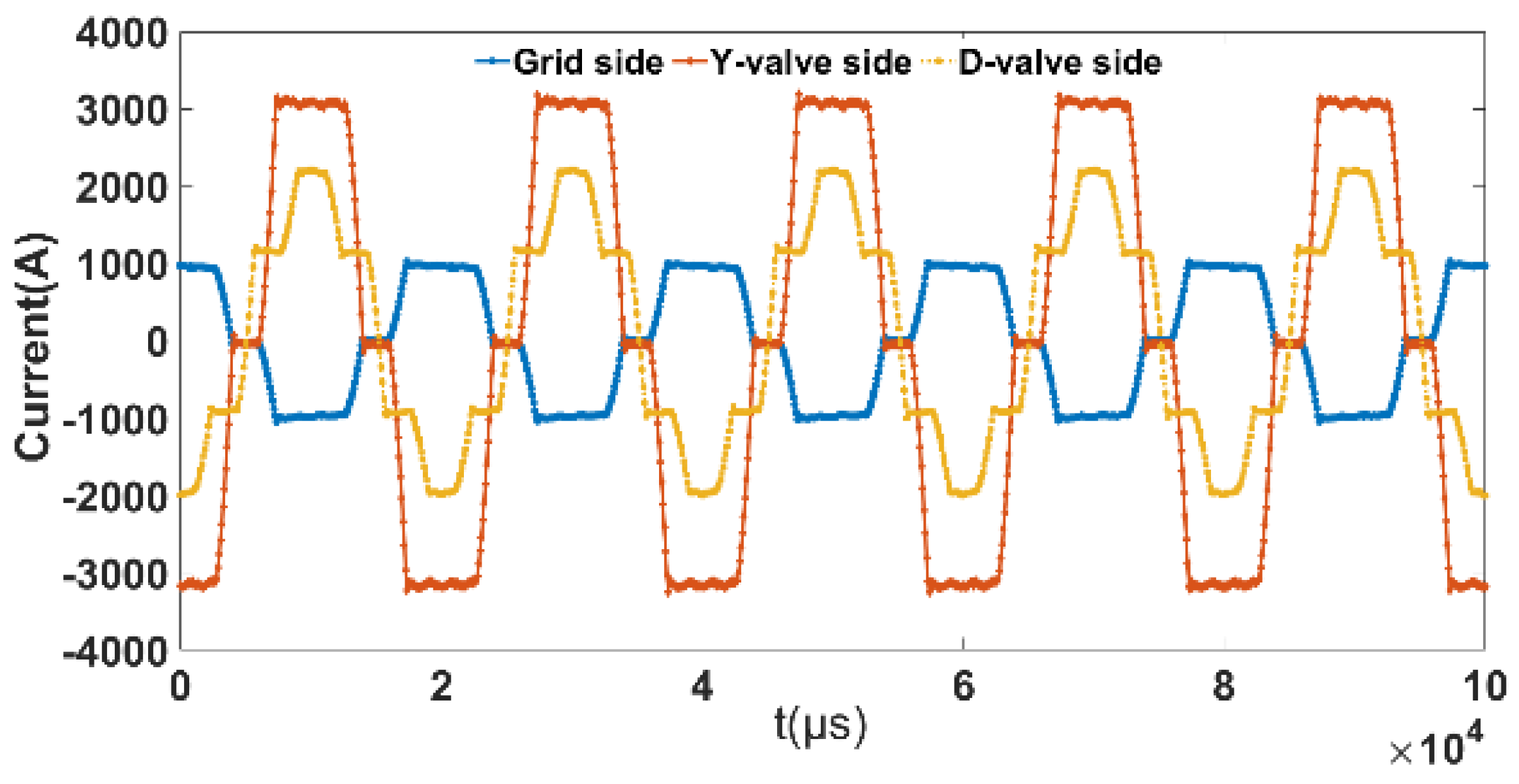
The valve side current is mainly determined by the load. Through the iron core flux linkage, a current will be induced in the grid side windings, so the grid side current will change with the valve side current. The Y−type and D−type connections will cause a difference in the valve side current distribution. Figure 6 shows grid-side current and different types of valve−side current.

Figure 6.
Winding harmonic current waveform.
From Table 3, the harmonic component with more content in the current is the (6k ± 1)th order. Worthy of our attention, the proportions of each current harmonics are the same, 17%, 10%, 3.5% and 2.4%, respectively.
Table 3.
Current harmonic components and content.
3. Numerical Model of Winding and Core Vibration Considering Harmonics
Compared with the working condition of power frequency, abundant voltage and current harmonics can increase tank vibration. Therefore, it is very important to study the vibration mechanism of iron core and winding under harmonics.
3.1. Iron Core Vibration Model under Harmonics
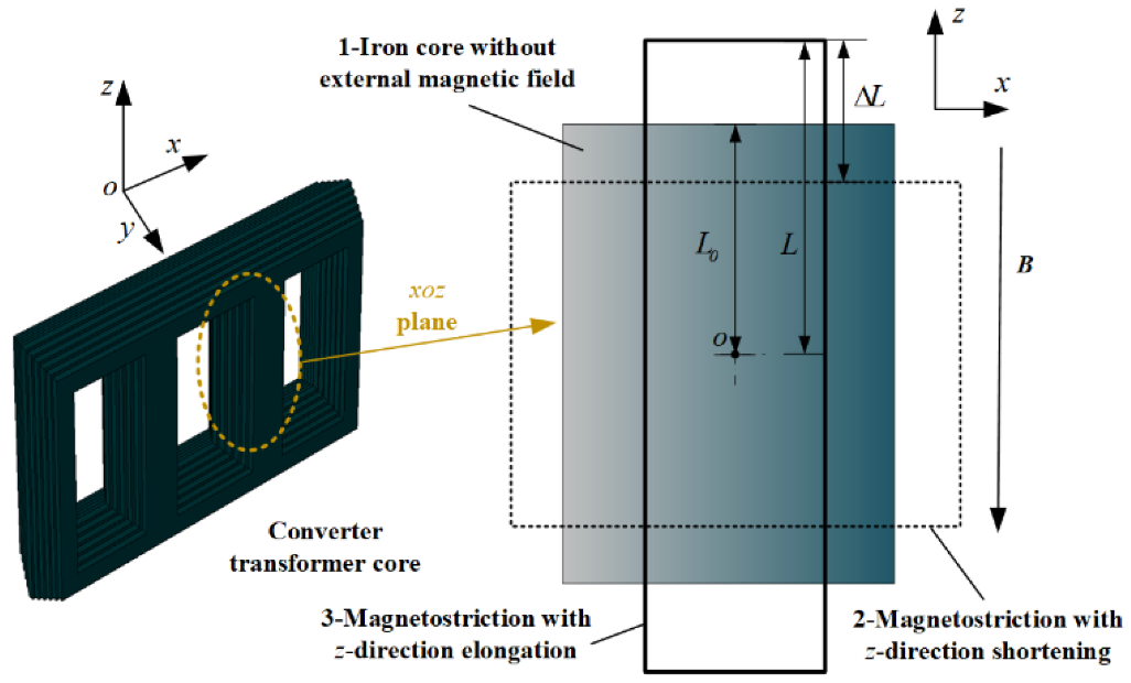
The core vibration mainly comes from the magnetostrictive effect of the silicon steel sheet. Figure 7 takes the right iron core column on the xoz plane as an example to analyze the magnetostrictive effect. Among these, 1 is the shape of the silicon steel sheet when there is no external magnetic field, and 2, 3 the height change of the silicon steel sheet under the external magnetic field, respectively. is the height of the silicon steel sheet without magnetic field, is change of height and , are the elongation and shortening under magnetostriction.

Figure 7.
The vibration of silicon steel sheet under magnetostriction.
When the primary side of the transformer is a sinusoidal voltage , the relationship between the voltage and the magnetic induction intensity in the iron core is obtained by Faraday’s law of electromagnetic induction [24,25].
is the number of turns of the primary winding and is the effective cross-sectional area of the iron core (m2) where, when the core magnetic flux is not saturated, the main magnetic flux generated by the sinusoidal voltage is also sinusoidally distributed.
When the primary side voltage is less than the rated voltage , the core magnetic flux is less than the material saturation magnetic flux density :
At this time, the magnetic flux of the iron core is unsaturated. Assuming that the actual magnetization curve of the material is regarded as a linear ideal magnetization curve, the saturation magnetic flux density has a linear relationship with the coercive force field strength .
—the saturation magnetic flux density (T), —the magnetic permeability (H/m), —the core coercivity field strength (A/m).
Combining (4) with , the core magnetic field strength can be obtained.
According to the magnetostrictive principle of the material under the alternating magnetic field , when the magnetic flux density of the iron core is not saturated, the rate of change of the height of the silicon steel sheet relative to the magnetic field is [6]:
is the saturation magnetostriction coefficient (ppm).
Equation (6) integrates the magnetic field , where the height change rate of the silicon steel sheet is:
Therefore,
Then, the core vibration acceleration in the z-direction is:
From Equation (9), under the sinusoidal power frequency voltage, when the iron core is unsaturated, the dominant frequency of the iron core vibration caused by magnetostriction is twice the voltage frequency, i.e., 100 Hz.
However, during the operation of the transformer, due to the influence of the saturation characteristics of the iron core (), the main magnetic flux generated by the sinusoidal voltage on the primary side is no longer a standard sine wave and will be distributed as a flat-topped wave. In this case, the magnetic flux contains many higher harmonic components.
The core magnetic intensity under the harmonic can be expressed.
—the magnitude of the fundamental magnetic induction intensity and —the magnitude of the kth harmonic magnetic induction intensity.
Based on Equation (8), the vibration acceleration of the iron core under harmonics is:
Therefore, affected by the iron core saturation characteristics, even if the primary side voltage is a sine wave, there are also some harmonic components in the core flux. The vibration of the iron core not only contains the fundamental frequency of 100 Hz but also contains more k-multiple frequency components of 100 Hz. Harmonic components in the magnetic flux expand the vibration spectrum, making the frequency components more complex.
According to the analysis in Section 2.3 of the paper, there is almost no harmonic component in the voltage on the grid side (primary side). Equation (9) can explain the core vibration and its relationship with the voltage. However, in practice, due to the influence of the stacking of silicon steel sheets, there is nonlinearity of the magnetization curve of the iron core. At this time, Equation (11) can better represent the iron core vibration law. The magnetic flux distribution of the iron core still contains some harmonic components under the sinusoidal voltage, resulting in the vibration of the iron core not only containing the fundamental frequency component 100 Hz, and there are also 100 Hz multiplier components such as 200 Hz and 300 Hz, 400 Hz, etc.
3.2. Winding Vibration Model under Harmonics
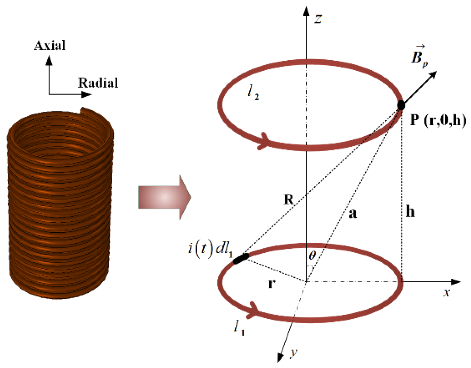
The load current in the converter transformer winding will generate axial and radial leakage flux in the surrounding space and the leakage current of the winding that generates the leakage flux is . The winding is a multi-turn coil, of which one turn can be regarded as an annular current-carrying wire. The power frequency current flows through the winding and the electromagnetic force generated at point p in the leakage magnetic field is shown in Figure 8.

Figure 8.
The electromagnetic force of coil in leakage magnetic field.
Among these, —coil 1 and coil 2, the coordinate origin is the center of coil 1 and the point p is any point on the coil, which is generally taken on the plane, and the coordinate is (r,0,h). —the leakage excitation current of the coil , —the leakage current calculation element, the coordinate is (x,y,z), R—the distance between any element on the coil and point p, r—the radius of the coil, h—the vertical distance between the coils , a—the distance from point p to the origin of coordinates, —the angle between point p and the z-axis.
According to the Biot-Savart law, the magnetic induction intensity generated by the leakage current of the coil at point p on the coil can be expressed as:
is the vacuum permeability; is the unit director of the calculated micro-element to point p, , .
For point p, the vector sum of generated by in the y direction is 0 according to the principle of symmetry. Therefore, the leakage flux is decomposed orthogonally and the radial leakage flux and the axial leakage flux are obtained.
Equation (13) integrates the curve of the coil to obtain the leakage flux distribution at point p. When the winding flows through the power frequency current , the leakage flux generated by the leakage current should also satisfy the sinusoidal distribution, as shown in Equation (14).
Among these, are the proportional coefficient of radial and axial leakage magnetic field and leakage excitation current respectively, are intermediate calculation parameters and the specific calculation method is Equation (15).
According to the analysis in Section 2.4 of the paper, the winding current at this time is:
is the fundamental current amplitude and is the current amplitude of each harmonic.
Since the leakage current is generated by the winding current, the leakage current also contains harmonic components, which should be consistent with the harmonic order of the winding current.
is the magnitude of the leakage flux fundamental current and is the magnitude of each leakage flux current harmonics.
According to the Ampere force calculation rule , the radial and axial electromagnetic force of the winding areas in Equation (18) and is the harmonic component of the electromagnetic force.
It can be seen from Equation (18) that the electromagnetic force of the winding is proportional to the product of the leakage current and the winding current . However, since the leakage current is excited by the winding current, and are proportional, , so it is traditionally believed that the fundamental frequency components of the electromagnetic force are proportional to the square of the winding current .
Through and the trigonometric function transformation rule, the winding vibration acceleration can be calculated from Equation (18). , , are the calculation coefficient corresponding to each vibration harmonic.
For Equation (19), when the winding current harmonic is 6k ± 1th, the winding vibration spectrum not only contains 100 Hz components but also contains 100 Hz frequency multiplication components such as 200 Hz, 300 Hz, 400 Hz, 500 Hz, etc. The high-frequency harmonic components of vibration can reach 1000 Hz.
It is particularly noted that, when the harmonic content is large, the harmonic coefficient in Equation (19) will increase, which will cause the dominant vibration frequency to shift to high frequencies such as 400 Hz, 800 Hz and 1200 Hz. In addition, due to the influence of harmonics, the effective value of the winding amplitude will superimpose the vibration harmonic amplitude, which will increase the winding vibration and lead to more serious winding deformation.
3.3. Theoretical Calculation of Vibration under Fundamental and Harmonics
The core vibration is mainly related to the grid side voltage and remains unchanged during operation. On the contrary, the winding vibration is greatly affected by the current harmonics. Taking the fundamental, 5th and 7th harmonics with more content as examples to calculate the winding vibration acceleration, the fundamental current is normalized and and are the winding current and leakage flux.
Calculated by equations and , the spectral distribution of the electromagnetic force F(t) and vibration acceleration a(t) of the windings with or without harmonics can be obtained,
—The amplitude of each harmonic of the electromagnetic force. —The amplitude of each harmonic of vibration acceleration. Table 4 shows the theoretical distribution of winding electromagnetic force and vibration harmonics under the common influence of 1 + 5 + 7th harmonics
Table 4.
Calculation of electromagnetic vibration amplitude with or without harmonics.
The dominant frequency of electromagnetic force and vibration without harmonics is 100 Hz. When there are harmonics, the spectrum of electromagnetic force and vibration acceleration becomes wider, i.e., 100–700 Hz. The frequency distribution of the alternating electromagnetic force is still 100 Hz, but the vibration dominant frequency will be shifted from 100 Hz to 300 Hz or 400 Hz.
4. Vibration Measurement Experiment Design
4.1. Vibration Measurement and Sensor Parameters
The vibration measurement test platform is divided into measurement sensors, data acquisition and signal analysis and each component is connected by a signal transmission line; the specific construction is shown in Figure 9.
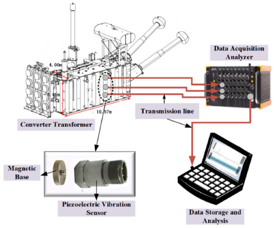
Figure 9.
Vibration measurement test platform.
The vibration sensor is attached to the tank wall with a magnetic base. Table 5 shows the sensor-related parameters. The sampling frequency of vibration data is 50 kHz.
Table 5.
Vibration sensor technical parameters.
4.2. Sensors Layout
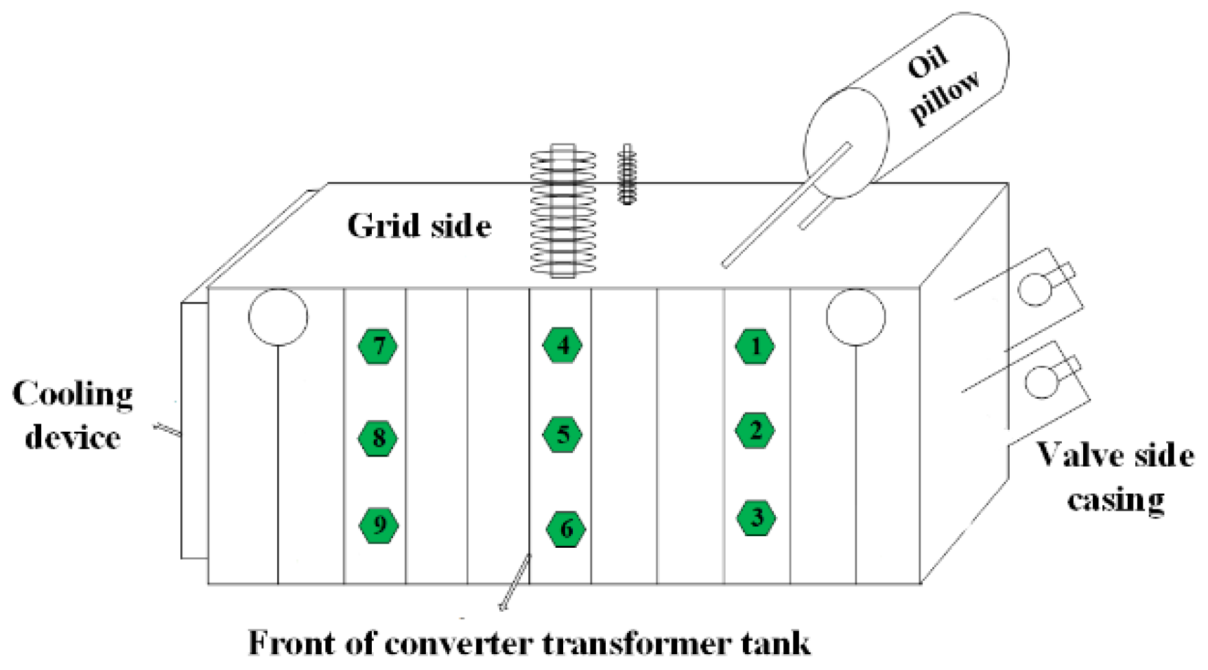
During the vibration measurement, the center position of the converter transformer vibrates most violently, so the vibration sensor layout adopts a regular arrangement around the center of the tank (measurement point 5). Nine measuring points are arranged on the side of the tank and the specific layout is shown in Figure 10.
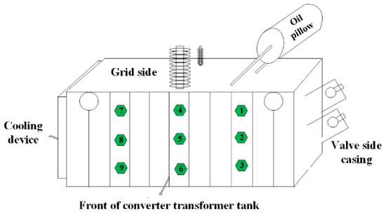
Figure 10.
Vibration Sensor Layout.
4.3. Vibration Condition Design with or without Harmonics
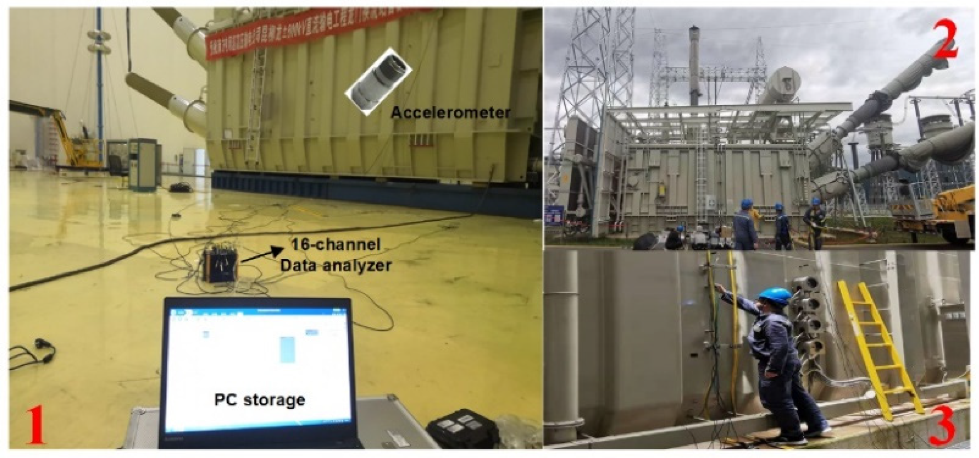
In this paper, the vibration signals of 12 converter transformers under harmonics are measured. The winding vibration under sinusoidal current was also measured based on the load test and the core vibration under sinusoidal voltage was measured based on the no-load test. Figure 11 shows the field test situation. Among these, 1,2—measurement of winding and core vibration without harmonic excitation based on load and no-load tests. 3—vibration measurement of in-service converter transformer under harmonic action

Figure 11.
Vibration measurement with or without harmonic excitation.
5. Results and Discussion
5.1. Winding and Core Vibration under Sinusoidal Excitation (No Harmonics)
5.1.1. Winding Vibration under Sinusoidal Current
During the load test, the valve side winding is short-circuited and the transformer runs in the rated state (820A/2551A) when the load grid side voltage is very small (5~10)% , . Analyzed by Equation (9), compared to the winding vibration, the core vibration caused by the voltage can be ignored. Figure 12 shows the grid side and valve side winding sinusoidal currents and vibration waveform.
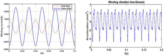
Figure 12.
Winding sinusoidal current and vibration without harmonics.
When a sinusoidal current flows through the winding, the winding is in a stable vibration state with a maximum amplitude of 3.63 m/s2.
It is necessary to convert the vibration time-domain signal into the frequency domain. For aperiodic vibration signal .
Fourier transformation is performed on the vibration signal.
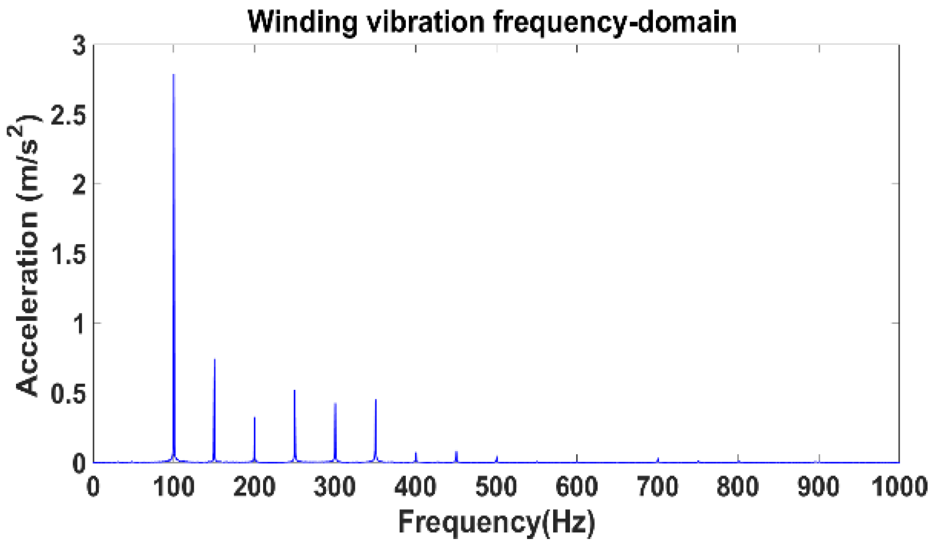
The vibration spectrum of the winding without current harmonics is shown in Figure 13.
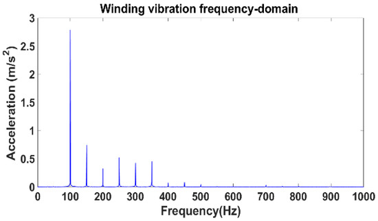
Figure 13.
Winding vibration spectrum without harmonic current.
The winding vibration spectrum under sinusoidal current excitation is concentrated in 0–500 Hz and almost does not contain high-frequency components above 500 Hz. The dominant frequency is 100 Hz, which is consistent with the mathematical expression derived from the theory. There are also harmonic frequencies such as 150 Hz, 200 Hz and 250 Hz, but the proportion of harmonic amplitude is not high.
5.1.2. Core Vibration under Sinusoidal Voltage
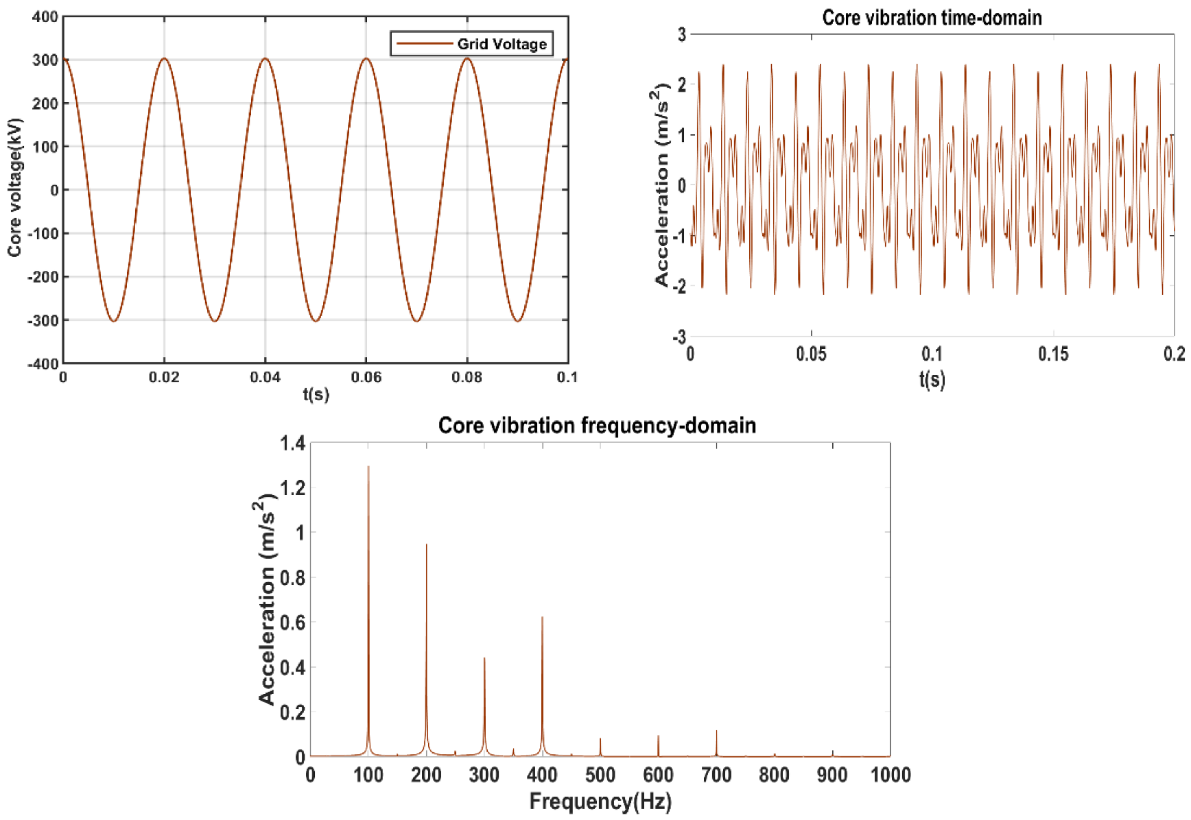
Under the no-load test, rated sinusoidal voltage 303 kV is input on the grid side and the valve side is open. At this time, there is a small no-load current in the grid-side winding, which is 0.02% , and no current in the valve-side winding, therefore the tank vibration is mainly the core vibration. Figure 14 shows the sinusoidal voltage, vibration time domain waveform and spectrum.
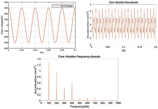
Figure 14.
Core vibration spectrum without harmonic voltage.
Under the excitation of rated grid side voltage, the maximum core vibration amplitude is 3.74 m/s2. In the frequency spectrum, the vibration dominant frequency is also 100 Hz, the amplitudes of the multiplied harmonics of 200 Hz, 300 Hz and 400 Hz are relatively large and almost no harmonics over 800 Hz are included. The 100 Hz frequency multiplication component in the spectrum is mainly caused by the nonlinear magnetization curve of the core.
5.2. Winding and Core Vibration under Sinusoidal Excitation (No Harmonics)
5.2.1. Vibration Peak-to-Peak Value in the Time Domain
Figure 15 shows the vibration waveforms at measuring point 5 during operation. The vibration peaks all exceed 20 m/s2 and the maximum amplitude of different types of converter transformers fluctuates between 20~40 m/s2.
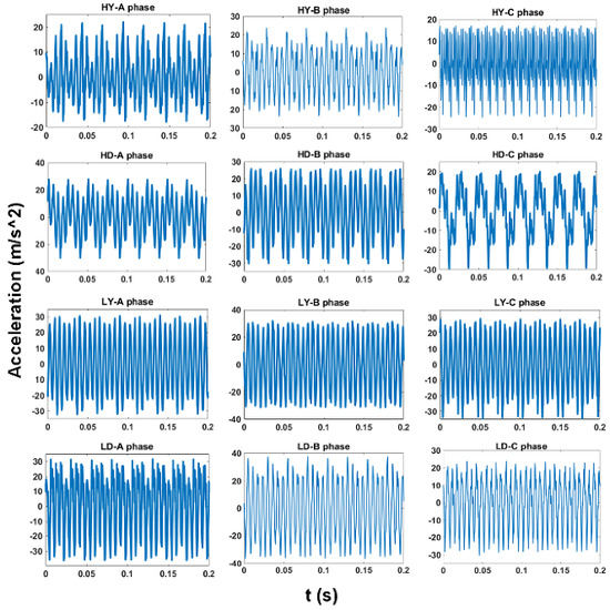
Figure 15.
The time−domain vibration signal.
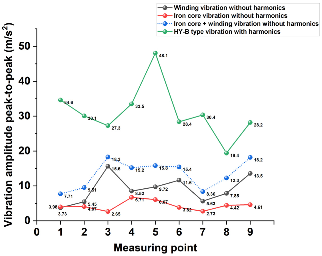
The vibration waveform distribution is asymmetric, so the peak-to-peak value can be used to describe the amplitude more accurately. The vibration without harmonics can be represented by the sum of the winding vibration under the sinusoidal current and the core vibration under the sinusoidal voltage. The vibration affected by the harmonics takes the HY-B type as an example, as shown in Figure 16.
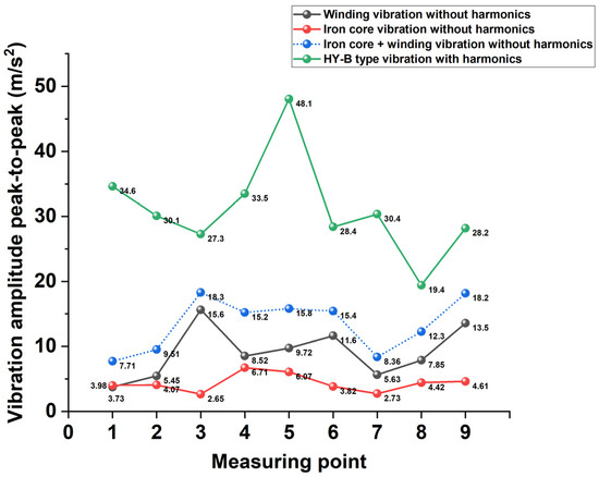
Figure 16.
Vibration peak-to-peak value with and without harmonics.
Under the sinusoidal rated excitation, the winding and core vibration amplitude is small. The maximum winding vibration is 15.6 m/s2 and the iron core is 6.71 m/s2. However, in the case of harmonics, the maximum amplitude is 48.1 m/s2, which is 3.04 times that under no harmonic condition. The results show that the vibration amplitude is superimposed by the fundamental and the harmonic current. The richer the harmonic content, the more severe the tank vibration. This requires structural parts that work under the action of harmonics to have higher mechanical strength.
5.2.2. Harmonic Vibration Spectrum
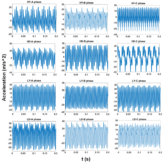
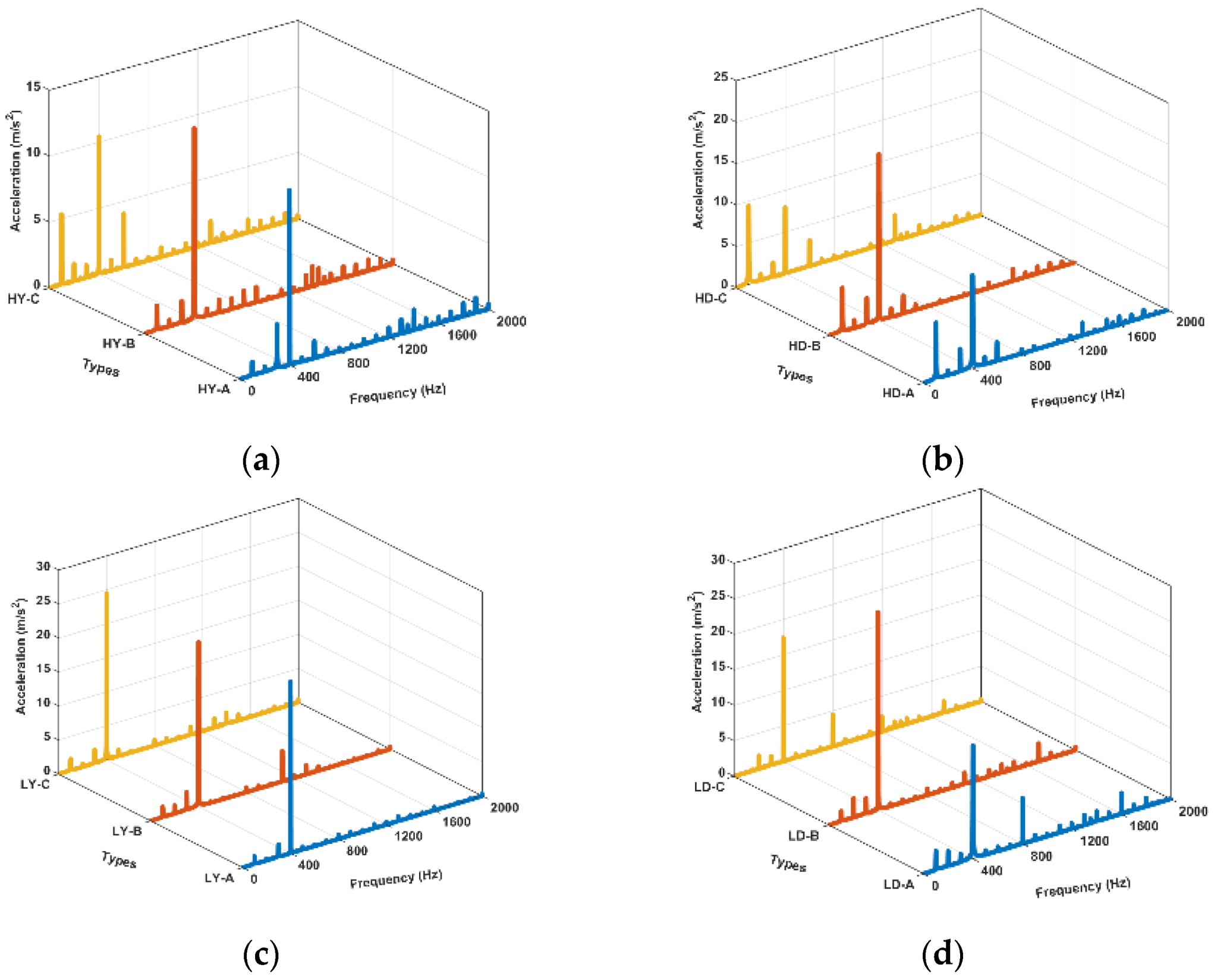
Figure 17 shows the vibration frequency domain features distribution at measuring point 5 of the tank, respectively.
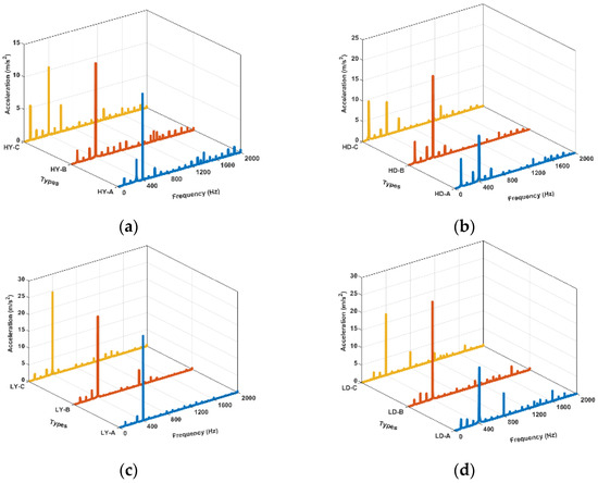
Figure 17.
Vibration spectrum. (a) HY-A/B/C phase; (b) HD-A/B/C phase; (c) LY-A/B/C phase; (d) LD-A/B/C phase.
The vibration spectrum distribution without harmonics is in 0–800 Hz. However, under the harmonic current, the frequency spectrum is wide, distributed from 0–2000 Hz. The dominant frequency is mainly 100 Hz or 400 Hz, and compared with sinusoidal excitation, becomes larger. In addition, high frequency vibration harmonics above 1000 Hz appear in large quantities.
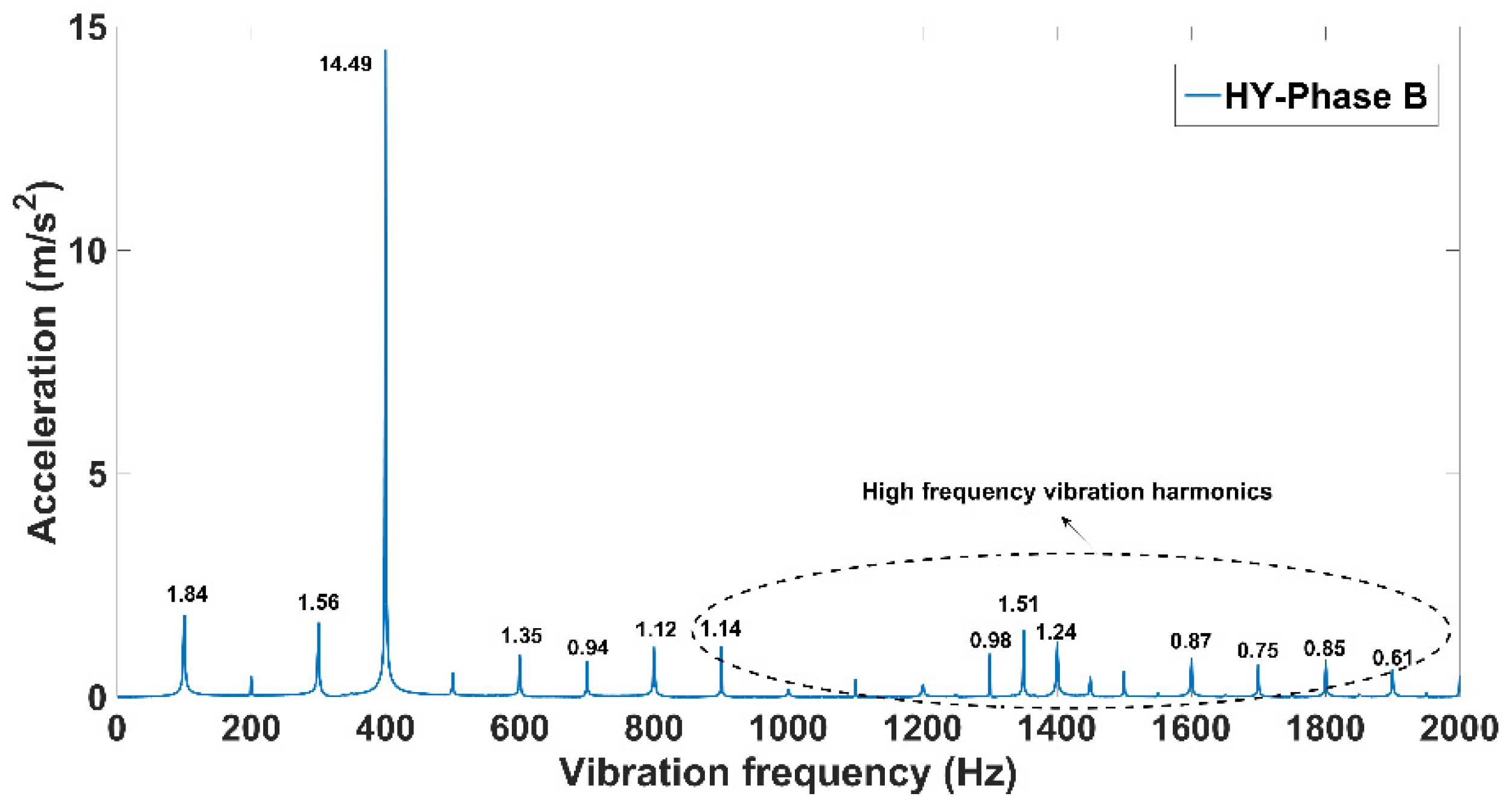
Figure 18 shows in detail the harmonic components above 1000 Hz in the vibration, where the amplitudes are larger at frequencies of 1300 Hz, 1350 Hz, 1400 Hz and 1600 Hz.
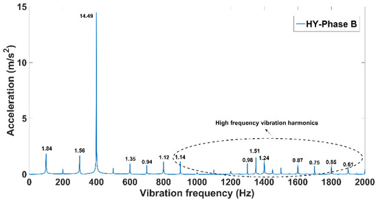
Figure 18.
Comparison of vibration spectrum with and without harmonics.
5.2.3. Dominant Frequency under Different Working Conditions
Table 6 shows the dominant frequency of winding and iron core vibration with or without harmonic influence.
Table 6.
Vibration dominant frequency with or without harmonic.
The 6k ± 1 current harmonics cause a large increase in the 300 Hz and 400 Hz amplitudes in the winding vibration. At the same time, due to the magnetic saturation characteristics of the iron core, the main magnetic flux contains harmonics, so the vibration not only contains the main frequency of 100 Hz but also contains a part of the 100 Hz frequency multiplication component. The vibrations of the two are coupled in the process of being transmitted to the tank so that the dominant frequency of the measured vibration is shifted to 400 Hz and the frequency spectrum also contains a large number of high-frequency harmonics.
However, the tank vibration includes the winding and core vibration; so, to elucidate the contribution of both to the tank, vibration simulations were performed.
5.3. Contribution of Winding and Iron Core Vibration under Harmonics
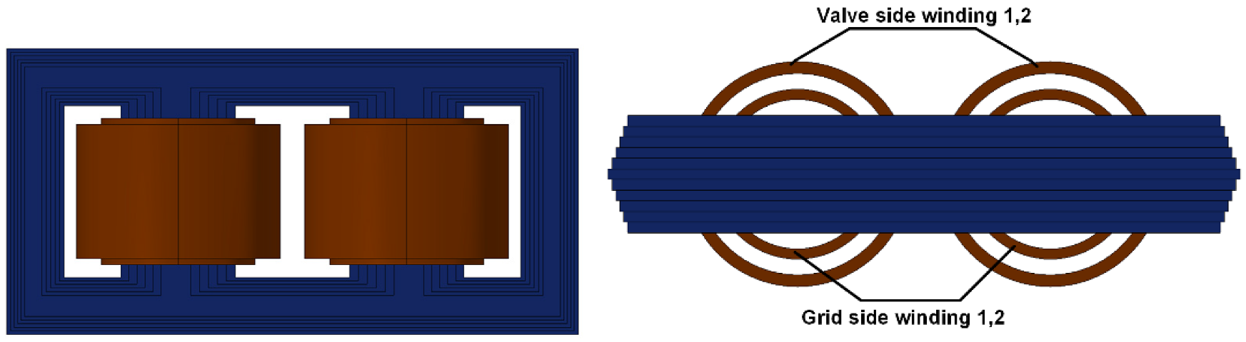
A simulation model was established based on the COMSOL software to analyze the vibration contribution of the iron core and winding under harmonics, as shown in Figure 19.
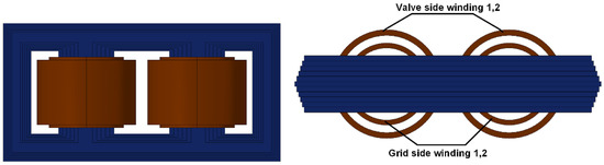
Figure 19.
Simulation model of converter transformer under harmonics.
According to the analysis in Section 2, the current excitation settings in the simulation are:
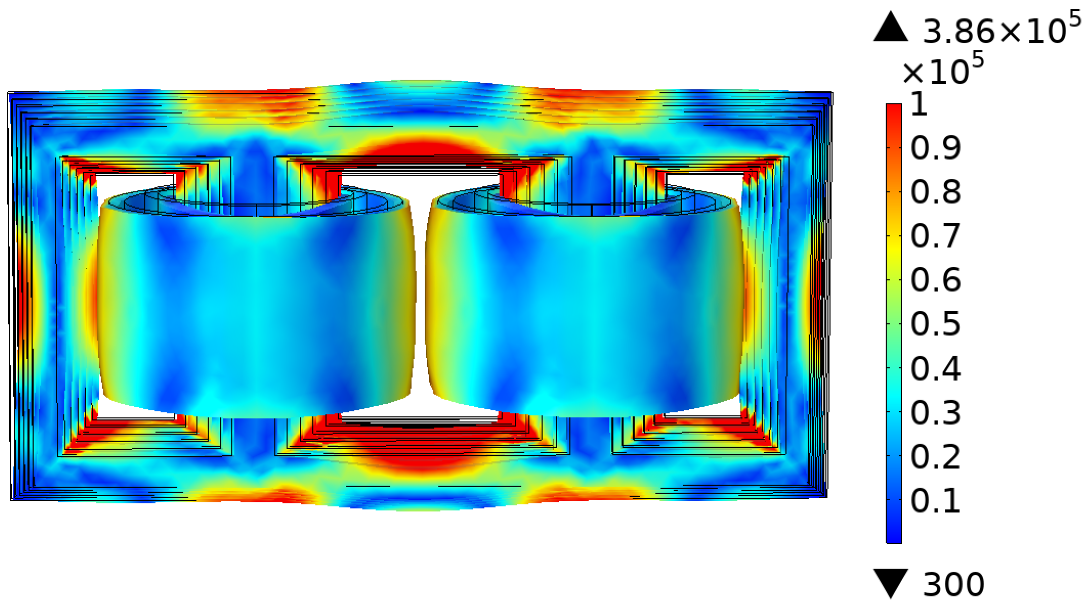
Figure 20 is a cloud map of stress and deformation distribution; it can be seen that the stress at the right-angle joint of the iron core, the upper iron yoke and the side yoke are larger and the stress in the middle of the winding is greater than that at the upper and lower ends. The maximum stress is .
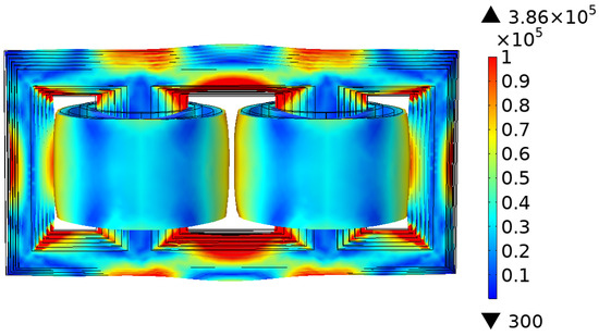
Figure 20.
Stress distribution and displacement deformation (N/m2).
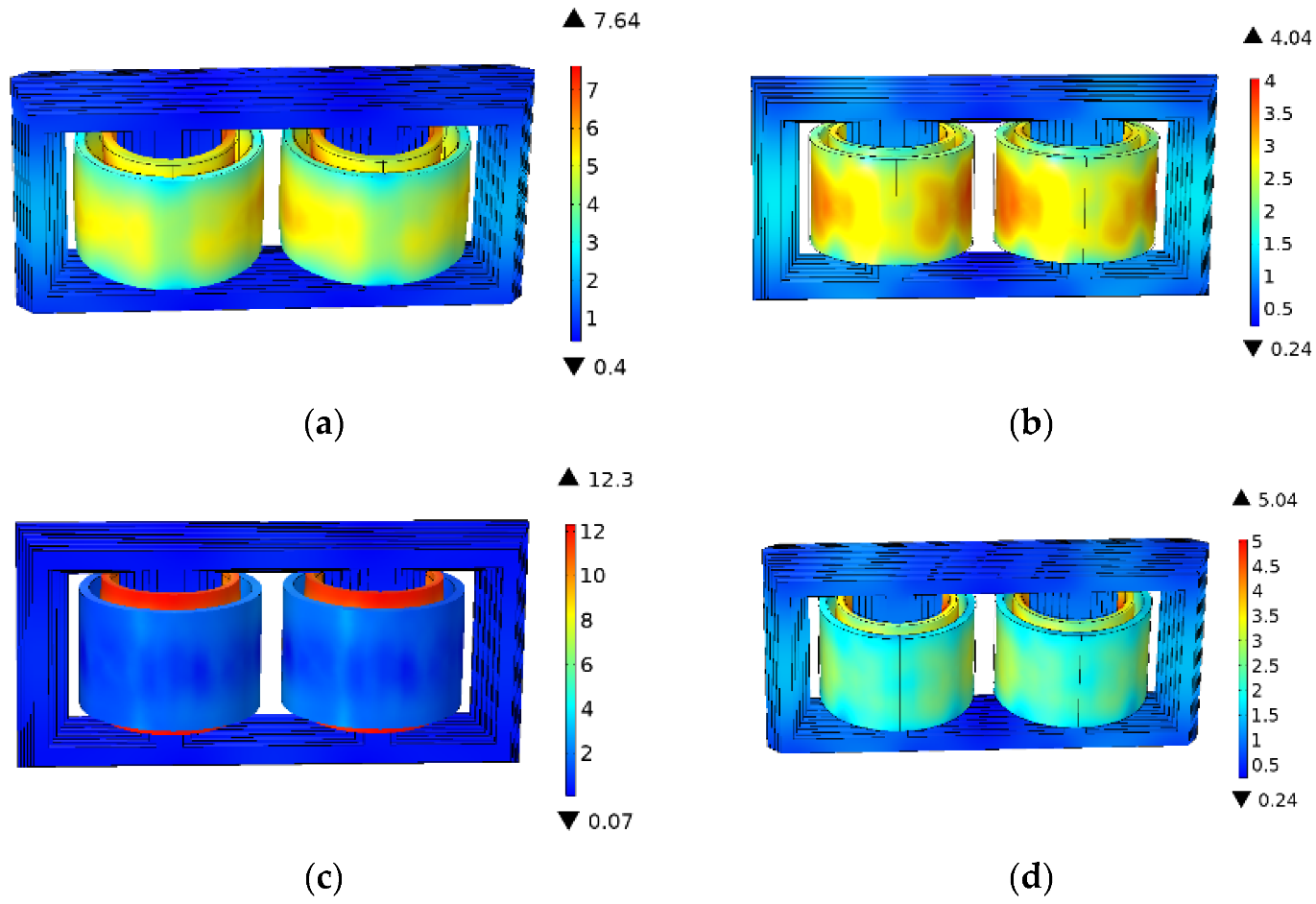
Figure 21 shows the vibration acceleration distribution at different times.
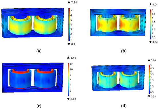
Figure 21.
The vibration distribution of winding and iron core (m/s2). (a) t = 0.005 s; (b) t = 0.010 s; (c) t = 0.015 s; (d) t = 0.020 s.
Under the influence of harmonics, the vibration amplitude of the winding in the operating converter transformer is greater than that of the iron core and the vibration acceleration of the grid side winding near the iron core column is the largest, at 12.3 m/s2.
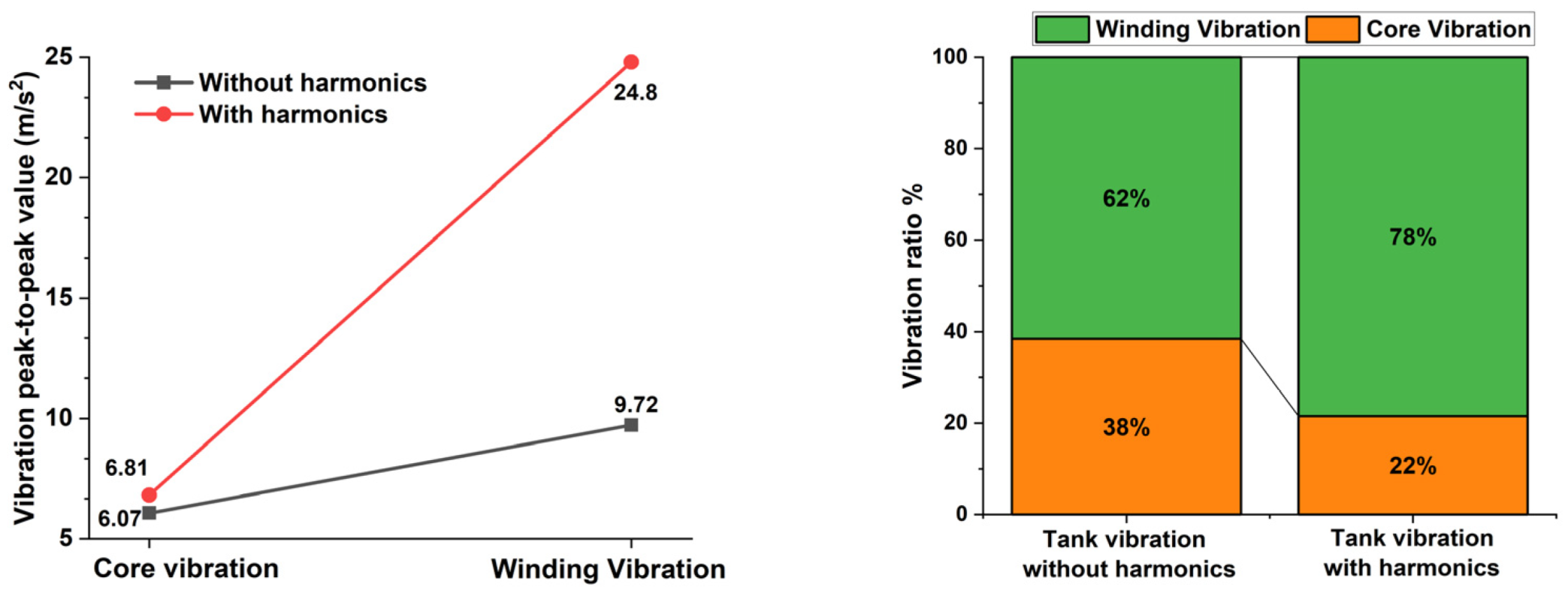
The winding vibration is generally the sum of the winding vibration on the grid side and the valve side. Figure 22 shows the contribution of the winding and the iron core in the tank vibration under the fundamentals and harmonics.

Figure 22.
Vibration change and proportion under harmonics.
The core vibration peak-to-peak value with and without harmonics is 6.81 m/s2 and 6.07 m/s2, respectively, an increase of 12.2%. The winding vibration increased from 9.72 m/s2 to 24.8 m/s2, a growth rate of 155.1%. It shows that when the grid-side voltage is constant, the current harmonics have little influence on the core vibration, which makes the winding vibration increase rapidly and dominates the tank vibration.
5.4. Contribution of Winding and Iron Core Vibration under Harmonics
Except for the current amplitude of the Y-type and the D-type, the rest of the operating environments are the same. The above analysis reveals that the current harmonics are an important reason for the increase of the vibration dominant frequency and high-frequency components.
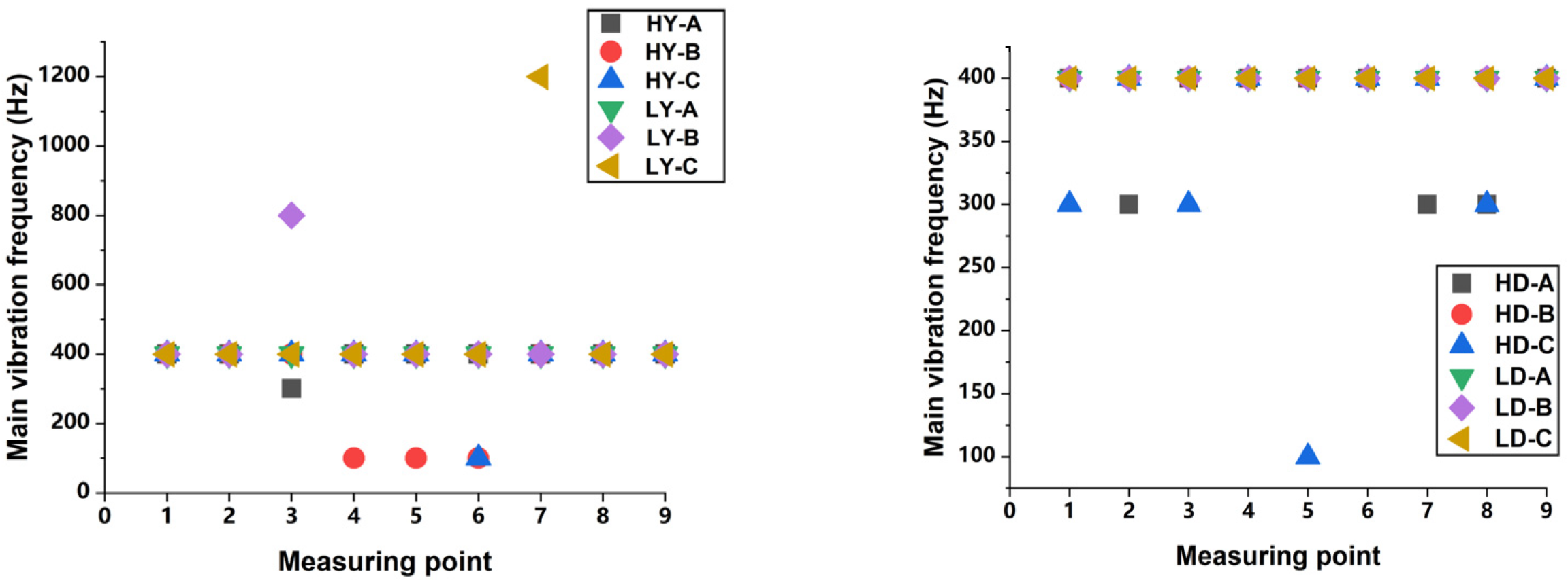
Therefore, the current amplitude is different under different connection methods, which will change the vibration characteristics. Figure 23 and Table 7 show the vibration dominant frequency characteristics at different measuring points of the tank.
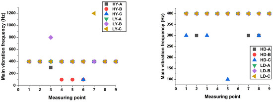
Figure 23.
Vibration dominant frequency of 6 Y/D-type transformers.
Table 7.
Dominant frequency ratio of all measuring points.
From Table 7, 87% of the measurement points have a dominant frequency of 400 Hz, accounting for the largest proportion, the other measuring points being 100 Hz, 300 Hz, 800 Hz and 1200 Hz, respectively. From Figure 23, Y-type’s vibration is the dominant frequency (e.g., 400 Hz, 800 Hz, 1200 Hz), while the D-type is, e.g., 100 Hz, 300 Hz, 400 Hz. This means the larger valve-side harmonic currents will more easily shift the dominant vibration frequency to high frequencies.
6. Discussion
The main research results include establishing a vibration numerical model considering harmonics and carrying out a rich analysis of vibration time-frequency characteristics. Combined with simulation analysis and test data, the influence mechanism of harmonic current on vibration amplitude and dominant frequency change is effectively clarified.
At present, the main object of vibration research is AC transformers, but with the wide application of HVDC transmission projects, it is extremely necessary to study the vibration characteristics of converter transformers. There are almost no harmonics in the AC transformer and the vibration dominant frequency is twice the current and voltage frequency (50 Hz), i.e., 100 Hz. However, for the converter transformer, the dominant frequency under 50 Hz excitation is still 100 Hz, which is similar to the results of previous AC transformer studies. However, it is completely different when it is connected to the grid. The rich 5th and 7th current harmonics change the magnetic flux density distribution between the windings so that the winding vibration is superimposed by multiple harmonic components, the dominant frequency changes to 400 Hz and other components of the spectrum exceed 1000 Hz. In addition, it is pointed out that the contribution of the winding is large, which can guide future vibration research to focus on the winding.
The above discussion effectively complements the current research on the impact of harmonic vibration. Based on the numerical model, engineers can calculate the vibration spectrum under harmonics and evaluate the stability of mechanical structures. More importantly, the special time-frequency features are beneficial to extract multi-feature parameters in vibration signals, which are used to construct mechanical fault identification methods and realize online monitoring of operating conditions.
Finally, the current research only considers the influence of harmonics and valve-side current. In fact, vibration is also related to oil temperature and oil flow circulation speed. The follow-up research work will combine the simulation software to study the change of vibration characteristics under multiple factors and establish a more comprehensive numerical model and vibration analysis method.
7. Conclusions
In this paper, the simulation and experimental study of the converter transformer vibration are carried out and the vibration characteristic distribution under harmonics is obtained.
- (1)
- Under operating conditions, the voltage harmonic components and contents on the grid side and valve side are different, while the current harmonic contents on the grid side and valve side are the same. Among them, the grid-side voltage contains almost no harmonics and the valve-side voltage has abundant (4k ± 1) odd and 6k even harmonics. The currents are dominated by (6k ± 1) odd harmonics. Then, the electromagnetic-vibration numerical model of winding and iron core is constructed based on harmonic distribution.
- (2)
- Harmonics will increase the vibration amplitude, the dominant frequency and the frequency spectrum. The vibration amplitude is more than 3 times that of no harmonics and under the 5th, 7th and other (6k ± 1)th current harmonics, the dominant frequency is mainly 400 Hz and there are many vibration harmonics in the range of 1000–2000 Hz. This is very different from the 100 Hz dominant frequency of the AC transformer.
- (3)
- The winding vibration is related to the current and harmonics, the iron core vibration is determined by the grid-side voltage and the two have different contributions to the tank vibration. The proportion of winding vibration under harmonics increases from 62% to 78%. It can be considered that the main vibration of the tank is winding vibration at this time.
- (4)
- The winding connection method will change the vibration dominant frequency distribution of the tank and the larger current and harmonics make it easier for the dominant frequency to shift from 400 Hz to 800 Hz or 1200 Hz.
The abundant harmonics of the converter transformer change the vibration dominant frequency and spectral distribution. The vibration numerical calculation model considering the influence of harmonics can effectively explain the vibration mechanism. In addition, the analysis results of vibration time-frequency characteristics and influencing factors are beneficial to extracting multi-characteristic parameters and realizing the diagnosis of winding mechanical faults combined with a deep learning algorithm. More importantly, there are many components above 1000 Hz in the vibration spectrum and it is easier to approach the tank’s natural vibration frequency to generate resonance, resulting in increased vibration and noise, thus affecting the stability of the mechanical structure. Therefore, the above research conclusions can also guide the structural parameters design of vibration reduction and noise reduction and provide corresponding experimental data support.
For the above discussion, the scope of future research includes the following aspects: (1) Provide the vibration numerical model to engineers for vibration calculation under harmonics. (2) Establish a vibration numerical model with multiple influencing factors, including oil temperature, flow rate and harmonics. (3) Combined with the proposed time-frequency characteristic parameters, the deep neural network algorithm is used to realize the vibration fault judgment of the converter transformer.
Author Contributions
Conceptualization, P.J. and Z.Z.; methodology, P.J.; software, Y.Y.; validation, P.J., Z.D. and Z.Z.; formal analysis, P.J.; investigation, P.J.; resources, Z.Z.; data curation, Y.Y.; writing—original draft preparation, P.J.; writing—review and editing, P.J. and Z.Z.; visualization, Z.D.; supervision, Y.Y.; project administration, Z.D.; funding acquisition, Z.Z. All authors have read and agreed to the published version of the manuscript.
Funding
This research was funded by [Natural Science Foundation of China] grant number [52077012] and [China Southern Power Grid Technology Project] grant number [CGYKJXM20190190].
Conflicts of Interest
The authors declare no conflict of interest.
References
- Tabrez, M.; Sadhu, P.K.; Lipu, M.S.H.; Iqbal, A.; Husain, M.A.; Ansari, S. Power conversion techniques using multi-phase transformer: Configurations, applications, issues, and recommendations. Machines 2022, 10, 13. [Google Scholar] [CrossRef]
- Shu, Y.; Chen, W. Research and application of UHV power transmission in China. High Volt. 2018, 3, 1–13. [Google Scholar] [CrossRef]
- Liu, D.; Li, X.; Cai, Z. Analysis of the Harmonic Transmission Characteristics of HVDC Transmission Based on a Unified Port Theory Model. IEEE Access 2020, 8, 8922–8934. [Google Scholar] [CrossRef]
- Zollanvari, A.; Kunanbayev, K.; Bitaghsir, S.A.; Bagheri, M. Transformer Fault Prognosis Using Deep Recurrent Neural Network over Vibration Signals. IEEE Trans. Instrum. Meas. 2021, 70, 2502011. [Google Scholar] [CrossRef]
- García, B.; Burgos, J.; Alonso, Á. Transformer tank vibration modeling as a method of detecting winding deformations—Part I: Theoretical foundation. IEEE Trans. Power Deliv. 2006, 21, 157–163. [Google Scholar] [CrossRef]
- Tanzer, T.; Pregartner, H.; Riedenbauer, M.; Labinsky, R.; Witlatschil, M.; Muetze, A.; Krischan, K. Magnetostriction of Electrical Steel and Its Relation to the No-Load Noise of Power Transformers. IEEE Trans. Ind. Appl. 2018, 54, 4306–4314. [Google Scholar] [CrossRef]
- Ni, Q.; Luo, L.; Fan, J.; Jin, Z. Harmonic loss analysis of converter transformer in LCL-HVDC system. Energy Rep. 2020, 6, 352–357. [Google Scholar] [CrossRef]
- Liang, C.; Xu, J.; Luo, L.; Li, Y.; Qi, Q.; Gao, P.; Fu, Y.; Peng, Y. Harmonic Elimination Using Parallel Delta-Connected Filtering Windings for Converter Transformers in HVDC Systems. IEEE Trans. Power Deliv. 2017, 32, 933–941. [Google Scholar] [CrossRef]
- Yamashita, K.I.; Kameda, Y.; Nishikata, S. A Harmonics Elimination Method Using a Three-Winding Transformer for HVDC Transmission Systems. IEEE Trans. Ind. Appl. 2018, 54, 1645–1651. [Google Scholar] [CrossRef]
- Kalpana, R.; Bhuvaneswari, G.; Singh, B.; Singh, S. Harmonic mitigator based on 12-pulse ac-dc converter for switched mode power supply. IET Power Electron. 2010, 3, 947–964. [Google Scholar] [CrossRef]
- Sun, W.; Yang, L.; Zare, F.; Xia, Y.W.; Cheng, L.; Zhou, K. 3D modeling of an HVDC converter transformer and its application on the electrical field of windings subject to voltage harmonics. Int. J. Electr. Power Energy Syst. 2020, 117, 105581. [Google Scholar] [CrossRef]
- Liu, X.; Yang, Y.; Huang, Y.; Jadoon, A. Vibration characteristic investigation on distribution transformer influenced by DC magnetic bias based on motion transmission model. Int. J. Electr. Power Energy Syst. 2018, 98, 389–398. [Google Scholar] [CrossRef]
- Pan, C.; Yi, S.; Su, H.; Shi, W. Excitation-vibration harmonic response research of transformer in dc biasing operation. IET Electr. Power Appl. 2019, 13, 410–417. [Google Scholar] [CrossRef]
- Yadav, S.; Mehta, R. Modelling of magnetostrictive vibration and acoustics in converter transformer. IET Electr. Power Appl. 2021, 15, 332–347. [Google Scholar] [CrossRef]
- Jiang, P.; Zhang, Z.; Dong, Z.; Wu, Y.; Xiao, R.; Deng, J.; Pan, Z. Research on distribution characteristics of vibration signals of ±500 kV HVDC converter transformer winding based on load test. Int. J. Electr. Power Energy Syst. 2021, 132, 107200. [Google Scholar] [CrossRef]
- Hu, Y.; Zheng, J.; Huang, H. Experimental research on power transformer vibration distribution under different winding defect conditions. Electronics 2019, 8, 842. [Google Scholar] [CrossRef]
- Shao, P.; Luo, L.; Li, Y.; Rehtanz, C. Electromagnetic vibration analysis of the winding of a new HVDC converter transformer. IEEE Trans. Power Deliv. 2012, 27, 123–130. [Google Scholar] [CrossRef]
- Simões, A.N.; Carvalho, D.J.; Morita, E.d.S.; Moretti, H.L.; Vendrameto, H.V.; Fu, L.; Torres, F.; Souza, A.N.d.; Bizzo, W.A.; Mazon, T. A Triboelectric Nanogenerator for Energy Harvesting from Transformers’ Vibrations. Machines 2022, 10, 215. [Google Scholar] [CrossRef]
- Cui, H. Faults diagnosis of converter transformer based on the vibration method. Adv. Manuf. Sci. Eng. 2013, 712, 2101–2106. [Google Scholar] [CrossRef]
- Smajic, J.; Hughes, J.; Steinmetz, T.; Pusch, D.; Mönig, W.; Carlen, M. Numerical computation of ohmic and eddy-current winding losses of converter transformers including higher harmonics of load current. IEEE Trans. Magn. 2012, 48, 827–830. [Google Scholar] [CrossRef]
- Pang, B.; Liang, J.X.; Liu, H. Intelligent Bearing Fault Diagnosis Based on Multivariate Symmetrized Dot Pattern and LEG Transformer. Machines 2022, 10, 550. [Google Scholar] [CrossRef]
- Radja, N.; Rachek, M.; Larbi, S.N. Non-destructive testing for winding insulation diagnosis using inter-turn transient voltage signature analysis. Machines 2018, 6, 21. [Google Scholar] [CrossRef]
- Chen, H.; Fan, M.; Su, W.; Guo, Y.; Huang, Y. Effects of particle erosion on the submersible pump in an ultra-high voltage transformer. Energy Rep. 2021, 7, 7072–7081. [Google Scholar] [CrossRef]
- García, B.; Burgos, J.C.; Alonso, Á. Transformer tank vibration modeling as a method of detecting winding deformations—Part II: Experimental verification. IEEE Trans. Power Deliv. 2006, 21, 164–169. [Google Scholar] [CrossRef]
- Ji, S.; Luo, Y.; Li, Y. Research on extraction technique of transformer core fundamental frequency vibration based on OLCM. IEEE Trans. Power Deliv. 2006, 21, 1981–1988. [Google Scholar]


Publisher’s Note: MDPI stays neutral with regard to jurisdictional claims in published maps and institutional affiliations. |
© 2022 by the authors. Licensee MDPI, Basel, Switzerland. This article is an open access article distributed under the terms and conditions of the Creative Commons Attribution (CC BY) license (https://creativecommons.org/licenses/by/4.0/).