Abstract
In this study, a robotic fish inspired to carangiform swimmers has been developed. The artifact presents a new transmission system that employs the magnetic field interaction of permanent magnets to ensure waterproofness and prevention from any overload for the structure and the actuating motor. This mechanism converts the rotary motion of the motor into oscillatory motion. Such an oscillating system, along with the wire-driven mechanism of the tail, generates the required traveling wave in the robotic fish. The complete free swimming robotic fish, measuring in length with a mass of only , was able to maintain correct posture and neutral buoyancy in water. Multiple experiments were conducted to test the robotic fish performance. It could swim with a maximal speed of body lengths per second () at a tail beat frequency of and an electric power consumption of . Furthermore, the robotic fish touched the upper bound of the efficient swimming range, expressed by the dimensionless Strouhal number: at tail beat frequency. The lowest energy to travel 1 meter was Joules for the final prototype. Future works will focus on endowing the robot with energy and navigation autonomy, and on testing its potential for real-world applications such as environmental monitoring and animal–robot interaction.
1. Introduction
1.1. General Framework
By reproducing the working principles of living organisms, roboticists may endow their artifacts with better capabilities of adaptation to interact with the environment, pushing the boundaries of engineered systems’ performance [1,2,3,4]. In addition, bioinspired robots can be employed to investigate social cooperative behaviors and manipulate groups of animals to deepen the knowledge on self-organization and the evolution of communication [5,6].
Recently, many studies have focused on animal–robot systems, in which robotic fish were manufactured to investigate animal social interactions, but in most cases, the biomimetic artifacts had no or limited actuation systems; thus, they required to be actively moved by external robotic platforms [7,8,9,10,11]. Due to the experimental constraints, these studies were mainly conducted in laboratory conditions.
This work is aimed at preparing the ground for the development of a robotic fish inspired by pelagic species with carangiform swimming mode [6], to have an agent for carrying out animal–robot studies in the wild and for environmental monitoring.
1.2. Background
A brief literature review on carangiform robotic swimmers is provided, following as main references the review of Aditi R. and Atul T. [12], and the state of the art provided by White C. et al. [13]. In the following, the swimming speed of robots is indicated in both meters per second () and body lengths per second ().
In Po-tuna [14] and UC-Ika 1 [15], the actuation was obtained by means of motors connected to a peduncle system mechanism. Po-tuna had one motor for two links, it was long and weighed around , while UC-Ika was characterized by a four-degrees-of-freedom mechanism consisting of three links actuated by a single DC motor, it had no buoyancy systems, and had a mass of and length of . This robotic fish could reach a maximal swimming speed of , i.e., . Other tuna-inspired robotic fish are Tunabot Flex [13] and the previous generation Tunabot ([14,15]). Tunabot Flex measured in total length, in width, and in height ( height including caudal fin); with a mass of , this robot could reach a speed of at a tail beat frequency of and electric power consumption of . Tunabot in [16] was long with a mass of ; it could reach a speed of at a tail beat frequency of . Tunabot in [17] swam at at a tail beat frequency of ; the length was still . These two robots are characterized by a wire-driven mechanism. Other examples of wire-driven mechanisms are represented in [18,19,20]. The artifact in [18,19] was long, while in [20], body length was . Moreover, in [18,19], a maximal swimming speed of was reached at a tail beat frequency of . The Nanyang Arowana-like fish (NAF) [21] consisted of four modules (tail fin, electronics housing, ballast tank, fish head) that could be independently modified or even replaced. Propulsion was obtained with three joints actuated by two micromotors. This artifact was long, high, and wide, it weighed , and reached a maximal speed of . The Essex MT1 robotic fish [22] was divided into two main parts: the head box and the joint linkage. The head box, that was rigid and waterproof, accommodated the motors, the controller, and the battery pack, while the joint linkage consisted of 3 plastic boards and 15 metal shafts. This robot was long, wide, and high, and could swim at . The torpedo-shaped robotic fish presented in [23] used a central shaft moved by a DC motor; at the end of this shaft, there was a disc with eccentric shafts that drove the tail mechanism of the robot. This robot was proposed as an NAF with a modular design in [21]; it was long with weight and could reach a swimming speed of . The robotic fish developed in [24] consisted of a main flexible body and a propulsive tail fin. Its length, width, and height were , and respectively, and it could reach a speed of , i.e., , with a mass of . The mackerel-like robotic fish developed in [25,26,27,28,29] had a length of and a weight of 2.79 kg. It consisted of a streamlined flexible main body with a rigid propulsive tail fin. The actuation mechanism was a high-precision four-link assembly. Each link had a dedicated servomotor that enabled it to rotate with respect to the adjacent links, and the transmission was obtained by means of belts with minimal friction forces thanks to roller bearings. The maximum swimming speed was . The carangiform robotic swimmerflex developed in [30] was actuated by a DC motor through a transmission system consisting of a polystyrene chloride sheet, a nylon line, and an L-shaped metal bar. This product was cm long and reached a swimming speed of at a tail beat frequency of with power consumption of . The robot in [31], actuated by 5 DC motors with a caudal fin produced from wood laminates and pectoral fins of cast epoxy, was long, and could swim at at a tail beat frequency of and power consumption of . In [32], three rigid links were moved by a single DC motor through an eccentric wheel; the total length was , and the maximal swimming speed was , corresponding to a tail beat frequency of and power consumption of .
Lastly, in the frame of smart actuator-based robotic fish, it is possible to find solutions based on shape-memory alloys (SMAs), ionic polymer metal composites (IPMCs), and macrofiber composite (MFC) piezoelectric laminates. In other studies ([33,34]) SMAs were used; the robot body was divided into three segments of equal length, and a structure of ribs was employed to support the silicon skin that gave the robot its three-dimensional shape. This robot was long, had a weight of , and it could reach a speed of (). In [35], the artifact presented a rigid body and an IPCM caudal fin; it was long with a mass of and a maximal speed of around . In [36], an IPCM actuator was used. The body was a rectangular plastic box that fixed an electrode at the bottom to drive the IPCM strip actuator. This latter was , and at its end, a mm plastic fin was fixed. The total weight was and the maximal speed was . MFC piezoelectric laminates were used in [37], where the robotic artifact was long with a maximal swimming speed of at a tail beat frequency of . In these conditions, the electric power consumption was . Table 1 summarizes the characteristics of the robotic artifacts under consideration, also reporting the Strouhal number when available. When provided data were enough to calculate the work per meter and the cost of transport (COT), these quantities were calculated and reported. These two data, as the already mentioned Strouhal number, are also indicative of swimming efficiency.

Table 1.
Relevant works from the available literature that was considered to frame the context of the present research study.
1.3. Aim of This Work
In this paper, a tethered robotic fish with carangiform swimming mode is developed. By following the approach of [21] and [23], the proposed robotic fish is characterized by a modular structure with a biomimetic wire-driven (similar to that in [38]) design that resembles the contraction and relaxation of the lateral tail muscles. The actuation was realized with a single DC micro gear motor placed into the fish head. For the transmission, a novel mechanism was investigated that exploited the magnetic field interaction of permanent magnets. The main advantage of this innovative transmission principle consists of preventing the gear motor and the tail structure from any overload. When the fish tail becomes stuck, it simply stays still in position while the motor continues to run smoothly, breaking the magnetic coupling. This can avoid excessive stress for both the motor and the structure. Once the fish tail is released, the magnetic coupling and thus the tail waving are recreated. This work also aims at not exceeding the value of for total length, and achieving neutral vertical buoyancy and balance. Unlike most robotic fish of similar size, the proposed robotic fish could swim freely in the right position without any vertical strut supporting it.
The reminder of this research is organized as follows: Section 2 provides a general overview of the final manufactured prototype, the mathematical modelling of the traveling wave, and the procedure to size the propulsive tail of the fish, endowing the robotic artifacts with a proper balancing. In Section 3, all the experimental tests performed to characterize the performance of the robotic fish are presented together with the relative results.
2. Modelling and Design of the Robotic Fish
2.1. Overview of the Complete Prototype and Working Principle
Figure 1a,b provide the lateral and frontal views of the final assembled prototype. It is possible to clearly see the following:
- Hydrodynamic waterproof head.
- Three links, the last of which with a built-in caudal fin.
- Power supply wires.
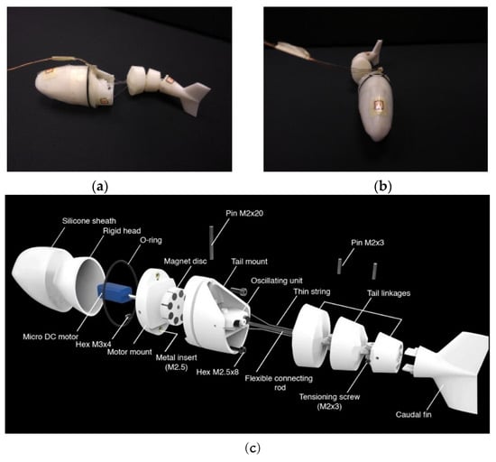
Figure 1.
Final fabricated robotic fish. Hydrodynamic waterproof head, three links, and power supply wires are visible. (a) Lateral view of the prototype; (b) frontal view of the prototype; (c) exploded view of the final CAD assembly of the robotic fish. The micro gear motor was housed inside the head. Permanent magnets were inserted into the rotating disc and into the oscillating unit. The flexible connecting rod and the lateral wires simulate the flexible spinal cord and the lateral muscular fibers, respectively, of a real fish.
Figure 1c shows an exploded view of the CAD robot assembly in which the internal elements are visible too. The head was produced with an ABS-based rigid part that was covered with a silicon sheath. The thin flexible connecting rod and the lateral wires simulating the flexible spinal cord and the muscle fibers, respectively, into the posterior part of the body, are also clearly visible. The micro-DC gear motor placed inside the head provides rotational motion to the disc in which the permanent magnets were inserted. The magnets on the right and left sides of the disc had opposite polarities (represented by red and blue). The oscillating unit had one magnet on each side with the same polarity orientation (represented in blue); thus, when one of them was attracted by the magnets on the disc, the other was repulsed, the tail pointed to the side of the repulsed magnet, and the whole posterior part of the body bent to the other side (Figure 2b and Video S1).
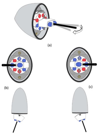
Figure 2.
Magnetic mechanism. The micro DC gear motor placed inside the head gives rotative motion to a plastic disc. Permanent magnets were inserted into the disc (a). The magnets on the right and left sides of the disk had opposite polarities (represented by red and blue). The oscillating unit had one magnet on each side with the same polarity orientation (represented in blue). When one of these magnets is attracted to those on the disc, the other is repulsed. The plastic rod (represented in black) always points to the side of the attracted magnet (b,c).
As already anticipated in Section 1, this mechanism prevents the gear motor and the structure from any overload due to the absence of any rigid mechanical connection between the motor shaft and the oscillating arm. The other design principle that was followed is modularity. The proposed fish robot platform consisted of two main parts: (1) a watertight head housing all necessary electronics and (2) an oscillating mechanism exposed to water. The nature and characteristics of these two parts can be modified or adjusted independently from each other. The oscillating mechanism was in turn divided into a principal part, consisting of an oscillating arm, three segments, and two hinges; and a final caudal fin inserted into the final joint. Moreover, such a platform allows for easily investigating several different combinations of heads, joints, and caudal fins. It is sufficient to fabricate different typologies for these parts and connect them together in different combinations.
2.2. Modelling of the Travelling Wave
The authors in [24] provided an equation to model the travelling wave in the case of carangiform robotic fish:
Equation (1) describes a body wave traveling from head to tail in a body-fixed coordinate system with the abscissa positive towards the tail (Figure 3), the linear and quadratic coefficient of the wave amplitude, is the body wave number in which represents the wavelength, is the wave frequency, and denotes time. Parameters and can be adjusted to achieve the desired body-caudal fin (BCF) swimming mode (Table 2). In this work, the reported values from [6,36] were used to model the traveling wave, and mimic fish swimming [39].
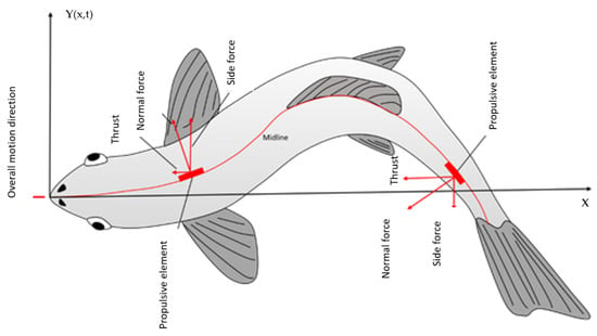
Figure 3.
Reference coordinate system with the origin in the tip of the fish snout and the x axis directed along the midline of fish body when it is in straight configuration, positive towards the tail.

Table 2.
Selected value of the parameters used for modelling the traveling wave.
2.3. Wire Mechanism Calculation
With reference to Figure 4, in which the unit of measurement is body length (BL) for both the horizontal and vertical axes, the fish body was piecewise approximated to mimic the characteristic wave form of the carangiform swimming mode. By plotting the waveform curve at different instants of time (Figure 4a), the maximal bending angle was around and could easily be approximated by means of three rigid segments and two connection hinges (Figure 4b). Looking at Figure 5a, Segment 1 was from Point B, where the plastic rod entered the ABS, to Point C (the center of Hinge 1), Segment 2 was from Point C to Point D (the center of Hinge 2) and Segment 3 was from Point D to Point E, i.e., the end of the fish. The oscillating arm was from Point A (the center of the oscillating unit hinge) and Point B, and was composed of the oscillating unit in which magnets were inserted and the flexible connecting rod (represented in Figure 1 and highlighted in black in Figure 2). As clearly shown in Figure 5, Segments 1 and 2 had two channels parallel to the mid axis of the fish (one to the right and one to the left) for the wires to pass through. Their distance from the mid axis was . In this first work, since the focus was not on the perfect reproduction of the carangiform waveform, relatively simpler choices were made: Segments 1 and 2 were assumed to have the same length, and their size was based only on the maximal bending point. Moreover, it was assumed that the total angle was equally divided between the two joints of each. In future works, an approach to establish the number, length, and position of segments and joints to closer mimic biological models will be adopted. Since, as specified in [40], head and body segments are also coupled in a timely way, the development and implementation of a refined head control also play a key role in future steps of this research.
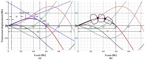
Figure 4.
Different colors have been used to draw the midline of the fish body at different instants of time. The used tail beat frequency is 1 Hz. It has been considered half a period (e.g. 0.5 s). Black curve corresponds to 0.1 s, purple curve to 0.2 s, green curve to 0.3 s, red curve to 0.4 s, and orange curve (nearly symmetric to black curve with respect to the x-axis) corresponds to 0.5 s. (a) The maximum angle of deflection of the mid line during the waving motion is investigated, and corresponds to 52°, (b) The mid line at its maximum angle of deflection can be well approximated using two joints.
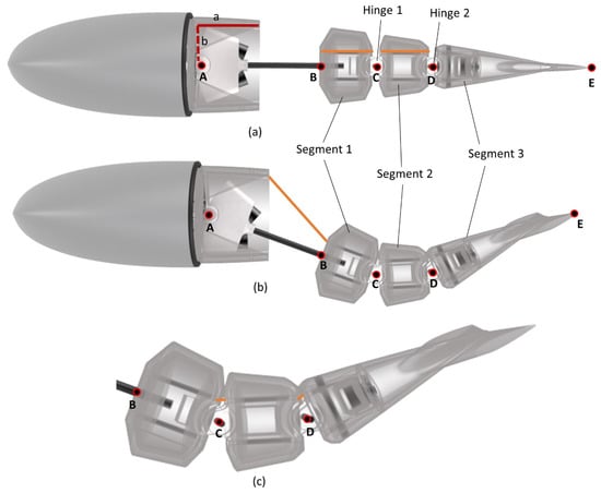
Figure 5.
Rendering of the robotic fish with straight position (a), bended position (b), particular of segments during bended position (c). Segments and joints are clearly shown. Point A represents the rotation hinge of the whole posterior part of the robotic fish, Points C and D represent the hinges of relative rotation between segments, and Points B and E are the starting point of Segment 1 and the final point of Segment 3, respectively.
Given the constraint on the robot total length, a total length of was assumed to be an indicative reference for the robotic fish. Moreover, a space of () was left between the facing sides of the adjacent segment to produce hinges. The axial distance between Point A, the hinge of the oscillating arm, and the wire attachment point was , while the transversal distance was (they are represented in Figure 5a with continuous and dot lines). The following measures were derived on the basis of Figure 5b:
It is now possible to calculate the required length of the wires for the robotic fish in bended configuration. This total length can be decomposed in several parts:
Length of the first part of the wire ().
This is represented by the orange segment in Figure 5b and was calculated by exploiting the schematic in Figure 6a. By considering triangle GHJ:
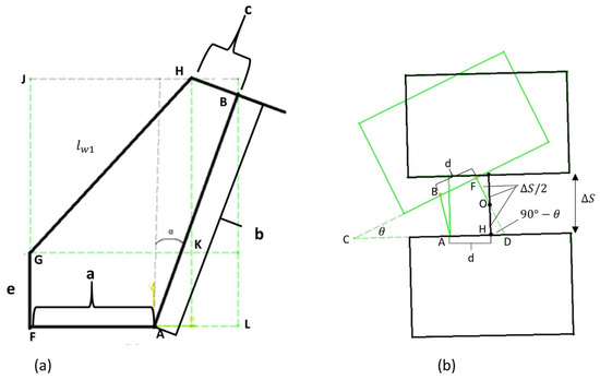
Figure 6.
(a) Schematic to calculate the length of the first part of wire . b represents the length of the connecting plastic rod and α the maximal bending angle equal to 26° (b) Schematic of relative position of two consecutive segments when the fish body is in straight configuration (black) and in maximal bending configuration (green).
Considering that , , and that, by looking at triangle BMH, , Equation (2) becomes:
Considering triangles ALM and BMH, the following holds:
Lastly, by substituting Equation (4) into Equation (3), the final expression of is:
Lengths of wire parts inside ABS of Segments 1 and 2 (and respectively).
These wire parts are represented in orange in Figure 5a and are easily obtained:
Lengths of wire parts between Segments 1 and 2, and between Segments 2 and 3 (and respectively).
These wire parts are highlighted in orange in Figure 5c. For the calculation, the schematic of Figure 6b was used. Black blocks represent the relative position of segments when the robotic fish body was in straight configuration, while green was used to represent the relative position of segments when the fish body was in maximal bending configuration. In this latter case, angle was equal to as already specified. In the schematic, the short wire part between segments is represented by , and the depicted situation was repeated twice: between Segments 1 and 2, and between Segments 2 and 3.
Considering the triangle ABC, the Carnot theorem states that:
Considering triangles DOH and DFC:
By substituting Equation (8) into Equation (7) according to the values of parameters, it is possible to conclude:
To conclude, the total necessary length of each of the two wires from the attachment point till they enter the ABS of Segment 3 is:
Table 3 shows the values of parameters that were used in the calculation.

Table 3.
Values of the parameters used in the wire-driven mechanism.
2.4. Final Robot Design
2.4.1. Magnet Selection
To select the appropriate magnets, the total drag force on the fish undulating tail was calculated. The fish body was simplified as a rectangular plank (); with reference to Figure 7, the worst-case drag for maximal transversal velocity () was considered. The equations to express hydrodynamic drag and the associated hydrodynamic torque are shown below:
where and are the length and maximal height of the fish body. Considering , the total angular deflection per cycle was . The maximal tail beat frequency was assumed to be equal to , and water density equal to ; thus, . On the basis of this number, neodymium circular magnets were ordered (N-35, ), and their separation force was experimentally calculated considering that the magnets were apart. This force was equal at and was used to calculate the magnet lever arm. Considering a single magnet configuration for the oscillating unit, the following holds:
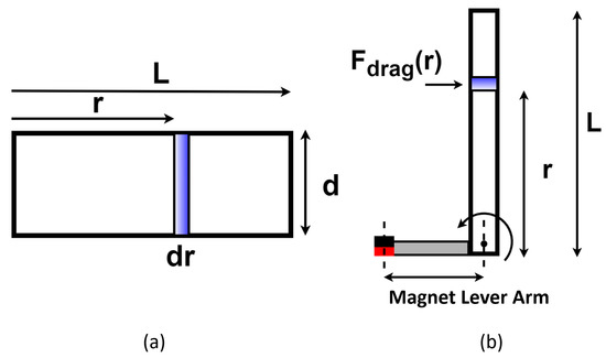
Figure 7.
Representative scheme to calculate total torque due to drag force on the tail: (a) simplified cross-sectional tail area; (b) arms of the oscillating mechanism.
Since the oscillating unit had two magnets, one for each side, each magnet had a lever arm of .
2.4.2. Motor Selection
Considering that the magnets on the rotor and those on the oscillating tail were around apart with an attraction force of , the gearmotor had to be capable of providing at least to break the magnetic coupling between the two attracting magnets facing each other; in this way, the gearmotor could maintain its rotation. On this basis, a micro metal gear DC motor with a stall torque of was ordered.
2.4.3. 3D Model and Manufacture of the Robotic Fish
After selecting and sizing all the components, the final CAD model of the robotic fish was developed in commercial software SolidWorks. The final dimensions of the 3D model were: length (almost the value taken as the reference in Section 2.3), width, and height, with a total mass of . The body profile was developed using NACA air foils. In particular, the body profile in the frontal plane was developed using NACA0018, while for the sagittal plane, NACA0026 was set. Lastly, the caudal fin was developed using the NACA0016 profile in the frontal plane with an aspect ratio of .
The complete fish was manufactured using a Zortrax M200 3D printer, which is based on FDM technology. Z-ULTRAT material was used, an ABS-based plastic with superior mechanical properties than those of pure ABS. After printing, the head was rendered waterproof using a silicone sleeve produced from Dragon Skin-30 by the Smooth-On company. A head mold was specifically produced and covered with a thin layer of wax to facilitate removing the silicone after curing. The adopted process was rotation molding and is shown in Figure S1: a thin coat of silicone was deposited on the open mold, and the head was rotated periodically to render it uniform. The final version was produced using 2 coats of silicone. Then, for the final assembly, the open end of the sleeve was clamped against the robotic body using an O-ring to render the rigid head of the robot waterproof.
2.4.4. Vertical Stability of the Robotic Fish
To allow for the fish to swim freely without any supporting mechanism such as floats or strings, the robotic fish needed to exhibit neutral buoyancy. This was taken into consideration and had an important impact on the design of the fish. Precisely for this reason, the tail was not covered with silicone: it would have negatively affected the vertical stability of the fish. The center of gravity and the center of buoyancy must also respect some requirements on relative position: they must be vertically aligned to achieve both horizontal and vertical stability; for vertical stability only, the center of gravity must be lower than the center of buoyancy. This generates a self-correcting torque if necessary to keep the fish upright in water. During the design process, the positions of the center of gravity and of the center of buoyancy were calculated with SolidWorks software to completely submerge the fish. On the basis of these calculations, an approximated amount of lead weights was calculated, and they were properly positioned to balance the fish in stable configuration.
3. Experimental Tests
To quantify the performance of the designed robotic fish, various experiments were conducted. Three different setups were built to calculate the following parameters:
- Motor voltage-to-tail beat frequency mapping.
- Electrical power consumption at different tail beat frequencies.
- Average swimming speed at different tail beat frequencies.
- Average thrust generated at different tail beat frequencies.
- Cost of transport at different tail beat frequencies.
- Strouhal number, which denotes the efficiency of swimming, at different tail beat frequencies.
In the following sections, the three experimental setups are discussed together with the associated results. All the experiments were performed in the same tank whose dimensions were .
3.1. Setup I
This setup was used for mapping the motor voltage to the tail beat frequency and for measuring the power requirements. The voltage-to-tail frequency mapping was crucial since, for all the following experiments, the robot would be powered by an external power supply without any active frequency control.
For this setup, a separate fish prototype was specifically built and attached to a frame through a custom designed bracket (Figure S2) properly shaped to allow for the undulating tail to be completely submerged in water. The head was not included in this setup. This choice is justified by the fact that the oversized gearmotor and the mechanism render the rotor dynamic independent from the external fluid dynamic actions acting on the robotic body that, in turn, depend on the intrinsic characteristics of the surrounding liquid and on the specific experimental setup that is adopted. In fact, with an oversized gear motor, the angular speed of the rotor is nearly independent of the load acting on the shaft. Moreover, in this study, due to the magnetic coupling transmission, the only load seen by the gear-motor shaft is the one of the magnetic attraction forces that must be overcome to keep the rotor in a state of rotation, and this force does not depend on external hydrodynamic actions. For these reasons, we adopted a more convenient setup with respect to the whole fish body (head included) that allowed for simpler measurements and major control on the experiment. Indeed, the resulting relation between applied voltage and tail beat frequency was also valid when the total fish body with the head included was left to swing freely.
Figure 8 shows the experimental process. To measure the tail beat frequency, rotations per second of the magnetic disc were recorded using a hall-effect sensor (SS413A). For reading data from the hall-effect sensor, a Arduino Mega board was used in which a dedicated code was developed and implemented. This provided the necessary time in milliseconds for the magnetic disc to complete each rotation. Data were transmitted in real time to a laptop by means of a universal asynchronous receiver–transmitter (UART) interface of Arduino. Voltage was provided to the motor by a benchtop power supply (Tenma 72-8345A) and was measured using a digital multimeter (Tenma 72-7730) with a USB port. The sampling frequency for this measurement was s. Similarly, the USB interface of the multimeter was exploited to record data of the intake electrical power with s sampling frequency again. For mapping the voltage-to-tail beat frequency, different voltage values were selected within the operating range of the motor. Each test was run till frequency samples had been collected. For calculating the power requirement, the test was performed for frequency values. The voltage was manually noted with another multimeter (Agilent U1231A), while current data were collected using the USB interface of the Tenma multimeter.

Figure 8.
Rotations per second of the magnetic disc were recorded using a hall-effect sensor (SS413A), while data were read with a microcontroller (Arduino Mega board). Then, data were transmitted in real time to a laptop by means of the universal asynchronous receiver–transmitter (UART) interface of the microcontroller.
The corresponding values of supplied voltage and measured frequency are reported in Table 4, while Figure 9 highlights a strong linear correlation between voltage and frequency . In this regard, Pearson’s correlation coefficient (PCC) [41] was calculated, and a value very close to 1 was recorded. This is indicative of a strong positive linear correlation [41] between applied voltage and tail beat frequency. Therefore, the relation between voltage and frequency can be approximated as shown in Figure 9.

Table 4.
List of the motor voltage values and the corresponding values of the tail beat frequency.
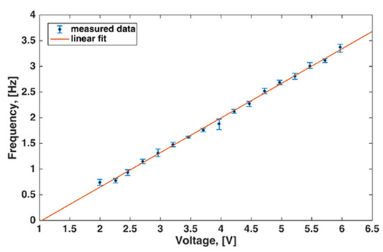
Figure 9.
Linear relation between the voltage supplied to the motor and the tail beat frequency. Points are the means of 100 frequency readings. Error bars indicate maximal and minimal values.
A suitable method to determine slope and intercept is to minimize the sum of the standard deviations about the line [41]. The following values were obtained:
Thus, Equation (13) becomes:
3.2. Setup II—Average Swimming Speed at Different Tail Beat Frequencies, Power Consumption, and Cost of Transport
With reference to Figure S3a, the second setup consisted of an aquarium, a calibration grid, some portable LED lights, and a top-mounted camera. The fish swam at different tail beat frequencies and it was recorded using a phone camera at video sampling rate. Markers were attached to the fish for easier tracking during the video analysis that followed. For experiments carried out under this setup, the robotic fish was completely unconstrained and free to swim. The fish had neutral buoyancy and, for all the experiments, swam just below the surface, as visible from the side view of this experimental setup (Figure S3b). It was powered by thin enameled wires that did not constrain the swimming of the fish in any way. The electric power consumption was measured and recorded by means of the Tenma multimeter.
For each tail beat frequency, at least six videos were recorded at sampling frequency, and one video at (slow motion). Out of these videos, the best four were selected for analysis with Kinovea software, which is free and open-source software used in motion analysis by various researchers for sports and motion analysis, and is also reliable as a video analysis tool [42].
Three analyses were carried out using the videos captured from this setup. Before starting the analysis of any video, the image plane was calibrated using the calibration grid. Every time, this operation was performed when the water was static with no ripples distorting the image. Squares on the grid measured on each side. Of course, the presence of water itself can affect measurements because lines of sight are deflected by this medium. This effect increases with water depth. To limit it, the grid was placed as close as possible to the robotic fish, taking care to not interfere with its kinematics. In future developments of this research study, dedicated software will be employed to counteract the effect of water depth and ripples, and conduct totally accurate measurements.
3.2.1. Swimming Speed Calculation
The forward swimming speed was calculated by tracking the marker attached to the head of the robotic fish. The marker was tracked (see Figure S4) only after steady-state swimming had been achieved, which was a few seconds after the release of the fish. The marker was tracked for a few seconds. From the results that contained the time-stamped position of the marker, the total horizontal displacement was divided by the time taken for that trial. This provided the average horizontal speed of the robotic fish. Once again, for each frequency, the best four videos were selected. The results of this analysis consisted of four swimming speed readings per tail beat frequency.
Figure 10 shows the sequence of images, while Figure 11a shows the relationship between the tail-beat frequency and the measured swimming speed in units of body length per second (). As already explained in Section 1, it is important to adopt body length as unit of measurement for distance to allow for a comparison with the performance of other fish, both robotic and real. The robotic fish had a maximal swimming speed of at the tail-beat frequency of . The average swimming speed increased approximately linearly with tail beat frequency. A sharp local increase in swimming speed was seen from to , followed by a dip. The swimming speed remained almost constant from to . Then, it again increased linearly with frequency. Pearson’s correlation coefficient was calculated in this case (data are reported in Table 5) to be . Thus, in this case, there was also quite strong linear relation, but less marked than the one detected in Section 3.1 between the supplied voltage and the tail beat frequency. The approximated relation is:
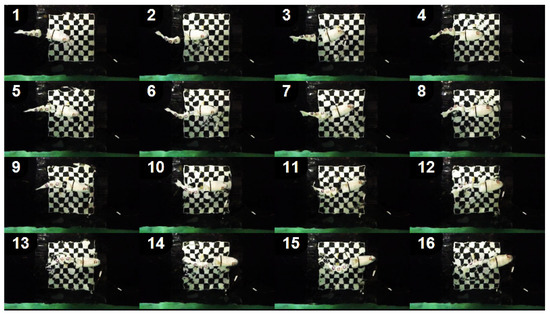
Figure 10.
Sequence of images of the robotic fish swimming with a tail beat frequency of .
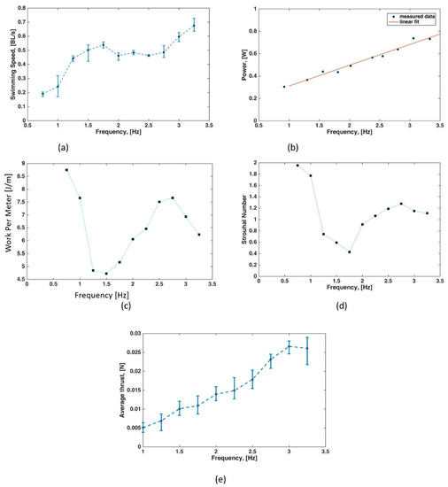
Figure 11.
Performance graphs. (a) Swimming speed (in ) versus tail beat frequency (in ). Points are the means of four swimming trials. Error bars denote maximal and minimal values. The average swimming speed increased approximately linearly with the tail beat frequency. A sharp local increase in swimming speed was seen from to , followed by a dip. The swimming speed remained almost constant from to . Then, it again increased linearly with frequency. (b) Power consumption by the motor (in watts) versus tail beat frequency (in hertz). (c) Energy (in joules) required to travel 1 meter versus tail beat frequency (in hertz). (d) Strouhal number versus tail beat frequency (in hertz). (e) Thrust (in newton) versus tail beat frequency (in hertz). Points are the means of four swimming trials; error bars denote maximal and minimal values.

Table 5.
Frequency data and relative swimming speed values.
3.2.2. Power Consumption
For each tail beat frequency experiment, the current consumption was measured using the Tenma digital multimeter. Data were collected using the USB interface of the multimeter with a sampling frequency of and are shown in Table 6. Figure 11b shows that the electric power consumption was an increasing function of the tail beat frequency. The maximal power was at frequency values of and . In this case, a strong linear relation was also evident. In fact, Pearson’s correlation coefficient was equal to , and the best linear fit was given by:

Table 6.
Frequency data and relative power consumption data.
3.2.3. Work per Meter and Cost of Transport
The work per meter () represents the energy spent to travel a distance, and can be expressed as the ratio between average electric power consumption and average swimming speed :
Figure 11c shows that the lowest energy required to travel 1 meter of distance was when tail beat frequency was . This means that, if a battery rated at () is installed in the water-tight head of the robot, this can swim a maximal distance of with a single charge. At this frequency the swimming speed was . If the fish swarm at its top speed of , its tail beat frequency was and the maximal traveling distance was . The cost of transport () consists of the energy consumption per unit distance and unit mass, and equals the ratio of the work per meter and the mass of the robotic artifact:
Therefore, in correspondence of the minimal value of the work per meter (), there was also the minimal value of the cost of transport:
3.2.4. Strouhal Number
The Strouhal number is a dimensionless quantity that represents the propulsive efficiency of oscillation-based swimming. The peak-to-peak tail tip amplitude was similarly obtained through video analysis with Kinovea. The tail tip of the robotic fish was tracked on the already calibrated image plane (Figure S5) and the amplitude was extracted from these tracked data. Referring to Figure 11d, the Strouhal number was always higher with respect to the optimal range, that is, . It approached, as the lower bound of the exhibited range, the Strouhal number of , which is considered to be optimal for swimming. In this case, the calibrated plate in Figure S5 was distorted by flow ripples. This rendered the measurements less accurate and conclusions on the Strouhal number less reliable. These data are reported for the sake of completeness with the purpose to apply compensatory image corrections in future developments and obtain more accurate data.
3.3. Setup III
The setup is visible in Figure S6. Thrust was measured for 10 different tail beat frequencies using a pre-calibrated load cell with accuracy. The arms of the mechanism ( and ) were measured before each reading. To calculate the final thrust, the following equation was used:
Figure 11e shows that the thrust increased linearly with the tail beat frequency. It reached a maximal value of at a tail beat frequency of and was almost the same for the tail beat frequency of (). In this case, Pearson’s correlation coefficient was equal to , and the equation of the best linear approximation was:
Figure S6 shows that the robot was slightly tilted upwards, but this should not have impacted the results because the lever arm was tilted the same way, so the propulsive force was always perpendicular to the lever arm.
4. Conclusions and Future Directions
In this study, a bioinspired robotic fish was developed by taking fish species with carangiform swimming mode as the biological reference. The artifact was actuated using a single micro-DC gearmotor. A new magnetic transmission system was proposed that consists of a clever arrangement of permanent magnets (neodymium) that converted the rotary motion of the motor into the oscillatory motion of the tail. This mechanism prevents both the structure and the motor from any overload in case the tail becomes stuck, and it was combined with a wire-driven solution to generate a propulsive travelling wave along the fish body.
The proposed design is modular, which aids in a quick assembly and permits to easily extend and/or modify the morphology to adapt to various needs that might emerge in future research developments and applications. The rigid head houses the electronics and can be independently sealed without affecting the tail beating mechanism.
The robotic fish could reach the maximal swimming speed of , and approached, as the lower bound of the exhibited range, the Strouhal number of , which is considered to be optimal for swimming. The robotic fish could maintain neutral buoyancy and swim freely in the water without any supporting floating device. It measures only in length, with a mass of just , making it the smallest and lightest carangiform-inspired robotic swimmer with self-balance stability among the relevant works in Table 1. With respect to these references, the robotic fish developed here exhibited quite good performance as regards maximal swimming speed. A major future application of this robotic fish is to approach wild aquatic animals; thus, a lesser nuisance and aversion effect on living organisms is preferred to better speed performance. Comparing the Strouhal number and power consumption is difficult because very few references provide these data. Regarding the cost of transport, the robotic fish had quite high consumption to travel 1 meter in relation to its mass ().
The main strengths of the proposed design are as follows:
- Modular design.
- Simple control.
- Light weight and small size with neutral buoyancy.
- Easy to manufacture.
Some shortcomings are:
- Noise due to magnet snapping (however, lower than that of propellers traditionally used in underwater vehicles).
- Absence of active buoyancy control.
- Very high frequencies are bracketed by the choice of gear motor.
- Power externally provided by means of wires.
The main future development of this work is the investigation of the possibility to use it in real-world applications, such as environmental monitoring. Improved versions of this artifact could be used in the study of animal–robot interactions [3,43,44] and in having artificial agents autonomously interacting with the environment [33].
To render the robot effective for these applications, some enhancing modifications are required, such as a more powerful gear motor to achieve higher frequencies without losing torque. In this way, the generated thrust would increase, and the cost of transport would be lower. Moreover, it is straightforward to implement autonomous control and navigation, and perform refined tests on these features. In this sense, wireless communication may be an effective solution because it allows for keeping the main control unit outside the robot, thus limiting weight and overall size [45,46].
In future studies, the key bending points of a real fish body, the optimal number of segments, and their lengths will be identified. As specified in [40], head and body segments are also coupled in a timely way; the development and implementation of a refined head control will also play a key role in future steps of this research work. Lastly, in this first work, no formal evaluation of the actual bending kinematics was presented, as the focus of the manuscript was the development and assessment of the novel magnetic transmission system. The swimming behavior of the updated robotic artifact will also be recorded with high-speed cameras to compare the theoretical form of the traveling wave and the one detected by the camera. A numerical evaluation of the difference will be performed.
Supplementary Materials
The following supporting information can be downloaded at: https://www.mdpi.com/article/10.3390/machines10090755/s1. Figure S1. Curing of the silicone sleeve for the robotic fish head. The 3D printed fish head was periodically rotated for a uniform silicone coating; Figure S2. Setup for mapping the motor voltage to tail beat frequency; Figure S3. Setup for measuring the swimming speed, work per meter, and Strouhal number. It consisted of an aquarium, a calibration grid, some portable LED lights, a top mounted camera, power source, and digital multimeters for measuring voltage and current; Figure S4. Tracking of the robotic fish’s tail tip by exploiting the calibrated plane. The fish in this picture is swimming with a tail beat frequency; Figure S5. Tracking of the robotic fish using Kinovea for swimming speed calculation and correction angle. The tracked marker is the one on the fish head. The fish in this picture is swimming with a tail beat frequency of 2.5 Hz; Figure S6. Setup for measuring the generated thrust. A pre-calibrated load cell was used; Video S1. Dynamic exploded view of the CAD robot assembly and the final assembled robotic fish swimming.
Author Contributions
Conceptualization, D.R.; methodology, D.R. and A.W.; formal analysis, D.R. and M.M.; investigation, D.R., M.M. and A.W.; writing—review and editing, D.R., M.M., A.W. and C.S.; supervision, D.R. and C.S. All authors have read and agreed to the published version of the manuscript.
Funding
This work was supported by the EU H2020-MSCA-RISE-2018 ECOBOTICS.SEA “Bio-inspired Technologies for a Sustainable Marine Ecosystem” (824043), and by EU H2020 FETOPEN Project “Robocoenosis-ROBOts in cooperation with a bioCOENOSIS” (899520). The funder had no role in the study design, data collection and analysis, decision to publish, or preparation of the manuscript.
Data Availability Statement
Not applicable.
Conflicts of Interest
The authors declare no conflict of interest.
References
- Yang, G.Z.; Bellingham, J.; Dupont, P.E.; Fischer, P.; Floridi, L.; Full, R.; Jacobstein, N.; Kumar, V.; McNutt, M.; Merrifield, R.; et al. The grand challenges of science robotics. Sci. Robot. 2018, 3, eaar7650. [Google Scholar] [CrossRef] [PubMed]
- Morimoto, Y.; Onoe, H.; Takeuchi, S. Biohybrid robot powered by an antagonistic pair of skeletal muscle tissues. Sci. Robot. 2018, 3, eaat4440. [Google Scholar] [CrossRef] [PubMed]
- Romano, D.; Donati, E.; Benelli, G.; Stefanini, C. A review on animal–robot interaction: From bio-hybrid organisms to mixed societies. Biol. Cybern. 2019, 113, 201–225. [Google Scholar] [CrossRef] [PubMed]
- Romano, D.; Benelli, G.; Donati, E.; Remorini, D.; Canale, A.; Stefanini, C. Multiple cues produced by a robotic fish modulate aggressive behaviour in Siamese fighting fishes. Sci. Rep. 2017, 7, 4667. [Google Scholar] [CrossRef]
- Kopman, V.; Laut, J.; Polverino, G.; Porfiri, M. Closed-loop control of zebrafish response using a bioinspired robotic-fish in a preference test. J. R. Soc. Interface 2013, 10, 20120540. [Google Scholar] [CrossRef]
- Phillips, A. Robot Fish: Bio-inspired Fishlike Underwater Robots. Underw. Technol. 2017, 34, 143–145. [Google Scholar] [CrossRef]
- Romano, D.; Benelli, G.; Hwang, J.S.; Stefanini, C. Fighting fish love robots: Mate discrimination in males of a highly territorial fish by using female-mimicking robotic cues. Hydrobiologia 2019, 833, 185–196. [Google Scholar] [CrossRef]
- Worm, M.; Landgraf, T.; von der Emde, G. Electric signal synchronization as a behavioural strategy to generate social attention in small groups of mormyrid weakly electric fish and a mobile fish robot. Biol. Cybern. 2021, 115, 599–613. [Google Scholar] [CrossRef]
- Brown, A.A.; Brown, M.F.; Folk, S.R.; Utter, B.A. Archerfish respond to a hunting robotic conspecific. Biol. Cybern. 2021, 115, 585–598. [Google Scholar] [CrossRef]
- Bierbach, D.; Mönck, H.J.; Lukas, J.; Habedank, M.; Romanczuk, P.; Landgraf, T.; Krause, J. Guppies Prefer to Follow Large (Robot) Leaders Irrespective of Own Size. Front. Bioeng. Biotechnol. 2020, 8, 441. [Google Scholar] [CrossRef]
- Porfiri, M.; Yang, Y.; Lemay, B.; El Khoury, R.; Clément, R.J.G.; Ghirlanda, S. Can robotic fish help zebrafish learn to open doors? Proc. SPIE 2019, 10965, 109650B. [Google Scholar]
- Raj, A.; Thakur, A. Fish-inspired robots: Design, sensing, actuation, and autonomy-A review of research. Bioinspiration Biomim. 2016, 11, 031001. [Google Scholar] [CrossRef] [PubMed]
- White, C.; Lauder, G.V.; Bart-Smith, H. Tunabot Flex: A tuna-inspired robot with body flexibility improves high-performance swimming. Bioinspiration Biomim. 2021, 16, 026019. [Google Scholar] [CrossRef] [PubMed]
- Kim, E.J.; Youm, Y. Design and dynamic analysis of fish robot: PoTuna. In Proceedings of the IEEE International Conference on Robotics and Automation, New Orleans, LA, USA, 6 April–1 May 2004. [Google Scholar]
- Masoomi, S.F.; Gutschmidt, S.; Chen, X.; Sellier, M. The kinematics and dynamics of undulatory motion of a tuna-mimetic robot. Int. J. Adv. Robot. Syst. 2015, 12, 83. [Google Scholar] [CrossRef]
- Zhu, J.; White, C.; Wainwright, D.K.; Di Santo, V.; Lauder, G.V.; Bart-Smith, H. Tuna robotics: A high-frequency experimental platform exploring the performance space of swimming fishes. Sci. Robot. 2019, 4, 34. [Google Scholar] [CrossRef]
- Wang, J.; Tran, H.; Christino, M.; White, C.; Zhu, J.; Lauder, G.; Bart-Smith, H.; Dong, H. Hydrodynamics and flow characterization of tuna-inspired propulsion in forward swimming. In Proceedings of the ASME-JSME-KSME 2019 8th Joint Fluids Engineering Conference, San Francisco, CA, USA, 28 July–1 August 2019. [Google Scholar]
- Zhong, Y.; Li, Z.; Du, R. A Novel Robot Fish with Wire-Driven Active Body and Compliant Tail. IEEE/ASME Trans. Mechatron. 2017, 22, 1633–1643. [Google Scholar] [CrossRef]
- Zhong, Y.; Song, J.; Yu, H.; Du, R. Toward a Transform Method from Lighthill Fish Swimming Model to Biomimetic Robot Fish. IEEE Robot. Autom Lett. 2018, 3, 2632–2639. [Google Scholar] [CrossRef]
- Chen, J.; Yin, B.; Wang, C.; Xie, F.; Du, R.; Zhong, Y. Bioinspired Closed-loop CPG-based Control of a Robot Fish for Obstacle Avoidance and Direction Tracking. J. Bionic. Eng. 2021, 18, 171–183. [Google Scholar] [CrossRef]
- Low, K.H.; Chong, C.W.; Zhou, C. Performance study of a fish robot propelled by a flexible caudal fin. In Proceedings of the 2010 IEEE International Conference on Robotics and Automation, Anchorage, AK, USA, 3–7 May 2010. [Google Scholar]
- Liu, J.; Dukes, I.; Hu, H. Novel mechatronics design for a robotic fish. In Proceedings of the 2005 IEEE/RSJ International Conference on Intelligent Robots and Systems, Edmonton, AB, Canada, 2–6 August 2005. [Google Scholar]
- Chen, W.; Xia, D.; Liu, J. Modular design and realization of a torpedo-shape robot fish. In Proceedings of the 2008 IEEE International Conference on Mechatronics and Automation, Takamatsu, Japan, 5–8 August 2008. [Google Scholar]
- Barrett, D.S.; Triantafyllou, M.S.; Yue, D.K.P.; Grosenbaugh, M.A.; Wolfgang, M.J. Drag reduction in fish-like locomotion. J. Fluid Mech. 1999, 392, 183–212. [Google Scholar] [CrossRef]
- Wen, L.; Wang, T.; Wu, G.; Liang, J. Hybrid undulatory kinematics of a robotic Mackerel (Scomber scombrus): Theoretical modeling and experimental investigation. Sci. China Technol. Sci. 2012, 55, 2941–2952. [Google Scholar] [CrossRef]
- Wen, L.; Wang, T.; Wu, G.; Li, J. A novel method based on a force-feedback technique for the hydrodynamic investigation of kinematic effects on robotic fish. In Proceedings of the 2011 IEEE International Conference on Robotics and Automation, Shanghai, China, 9–13 May 2011. [Google Scholar]
- Wen, L.; Wang, T.M.; Wu, G.H.; Liang, J.H. Hydrodynamic investigation of a self-propelled robotic fish based on a force-feedback control method. Bioinspiration Biomim. 2012, 7, 036012. [Google Scholar] [CrossRef] [PubMed] [Green Version]
- Wen, L.; Liang, J.; Shen, Q.; Bao, L.; Zhang, Q. Hydrodynamic performance of an undulatory robot: Functional roles of the body and caudal fin locomotion. Int. J. Adv. Robot. Syst. 2013, 10. [Google Scholar] [CrossRef]
- Wen, L.; Wang, T.; Wu, G.; Liang, J. Quantitative thrust efficiency of a self-propulsive robotic fish: Experimental method and hydrodynamic investigation. EEE/ASME Trans. Mechatron. 2012, 18, 1027–1038. [Google Scholar] [CrossRef]
- Fujiwara, S.; Yamaguchi, S. Development of Fishlike Robot that Imitates Carangiform and Subcarangiform Swimming Motions. J. Aero Aqua Bio-Mech. 2017, 6, 1–8. [Google Scholar] [CrossRef]
- Kumph, J.M. Maneuvering of a Robotic Pike. Ph.D. Thesis, Massachusetts Institute of Technology, Boston, MA, USA, 2000. [Google Scholar]
- Yu, J.; Zhang, C.; Liu, L. Design and control of a single-motor-actuated robotic fish capable of fast swimming and maneuverability. IEEE/ASME Trans. Mechatron. 2016, 21, 1711–1719. [Google Scholar] [CrossRef]
- Rossi, C.; Coral, W.; Colorado, J.; Barrientos, A. A motor-less and gear-less bio-mimetic robotic fish design. In Proceedings of the 2011 IEEE International Conference on Robotics and Automation, Shanghai, China, 9–13 May 2011. [Google Scholar]
- Rossi, C.; Colorado, J.; Coral, W.; Barrientos, A. Bending continuous structures with SMAs: A novel robotic fish design. Bioinspiration Biomim. 2011, 6, 045005. [Google Scholar] [CrossRef]
- Chen, Z.; Shatara, S.; Tan, X. Modeling of biomimetic robotic fish propelled by an ionic polymermetal composite caudal fin. IEEE/ASME Trans Mechatron. 2010, 27, 448–459. [Google Scholar] [CrossRef]
- Liu, B.; Hao, L.; Deng, J.; Liu, X. A remote operated robotic fish with temperature sensor based on IPMC actuator. In Proceedings of the 2009 Chinese Control and Decision Conference, Guilin, China, 17–19 June 2009. [Google Scholar]
- Erturk, A. Macro-fiber composite actuated piezoelectric robotic fish. In Springer Tracts in Mechanical; Springer: Berlin/Heidelberg, Germany, 2015. [Google Scholar]
- Xie, F.; Li, Z.; Ding, Y.; Zhong, Y.; Du, R. An Experimental Study on the Fish Body Flapping Patterns by Using a Biomimetic Robot Fish. EEE Robot. Autom. Lett. 2019, 5, 64–71. [Google Scholar] [CrossRef]
- Webb, P.W. Form and Function in Fish Swimming. Sci. Am. 1984, 251, 72–82. [Google Scholar] [CrossRef]
- Fetherstonhaugh, S.E.A.W.; Shen, Q.; Akanyeti, O. Automatic segmentation of fish midlines for optimizing robot design. Bioinspir. Biomim. 2021, 16, 046005. [Google Scholar] [CrossRef]
- Benesty, J.; Chen, J.; Huang, Y.; Cohen, I. Pearson Correlation Coefficient; Springer: Berlin/Heidelberg, Germany, 2009; pp. 1–4. Available online: https://link.springer.com/chapter/10.1007/978-3-642-00296-0_5 (accessed on 10 March 2021).
- Puig-Diví, A.; Escalona-Marfil, C.; Padullés-Riu, J.M.; Busquets, A.; Padullés-Chando, X.; Marcos-Ruiz, D. Validity and reliability of the Kinovea program in obtaining angles and distances using coordinates in 4 perspectives. PLoS ONE 2019, 14, e0216448. [Google Scholar] [CrossRef] [PubMed]
- Marras, S.; Porfiri, M. Fish and robots swimming together: Attraction towards the robot demands biomimetic locomotion. J. R. Soc. Interface 2012, 9, 1856–1868. [Google Scholar] [CrossRef] [PubMed]
- Landgraf, T.; Nguyen, H.; Forgo, S.; Schneider, J.; Schröer, J.; Krüger, C.; Matzke, H.; Clément, R.O.; Krause, J.; Rojas, R. Interactive robotic fish for the analysis of swarm behavior. Lect. Notes Comput. Sci. (Incl. Subser Lect. Notes Artif. Intell. Lect. Notes Bioinform.) 2013, 7928, 1–10. [Google Scholar]
- Boboc, R.; Moga, H.; Talabă, D. A Review of Current Applications in Teleoperation of Mobile Robots. Bull. Transilv. Univ. Bras. Ser. I Eng. Sci. 2012, 40653001. [Google Scholar]
- Sánchez-García, J.; García-Campos, J.; Arzamendia, M.; Reina, D.; Toral, S.; Gregor, D. A survey on unmanned aerial and aquatic vehicle multi-hop networks: Wireless communications, evaluation tools and applications. Comput. Commun. 2018, 119, 43–65. [Google Scholar] [CrossRef]
Publisher’s Note: MDPI stays neutral with regard to jurisdictional claims in published maps and institutional affiliations. |
© 2022 by the authors. Licensee MDPI, Basel, Switzerland. This article is an open access article distributed under the terms and conditions of the Creative Commons Attribution (CC BY) license (https://creativecommons.org/licenses/by/4.0/).