This chapter presents experimental data of damaged orifices after short-time operation and the results of the numerical calculations. Images of the damaged orifices during the short-time operation were obtained by scanning electron microscopy (SEM). The damage patterns and possible causes, like remaining particles, their number and size then served as boundary conditions for the numerical calculations. Calculating the interaction between those observed particles and the orifice jewel then allowed to estimate their individual damaging potential for given operating conditions.
The challenge in investigating processes in the high-pressure part of the waterjet system is that this area is very difficult or not accessible for measuring devices due to the required pressure resistance. Accordingly, in-situ observation is not possible. In addition, the particles and areas to be observed are extremely small. The advantage of combining experimental and numerical approaches is that measured data can be used to model processes that cannot be measured. Because of the experimental data, the boundary conditions always correlate with real measured values and can also be easily modified and thus the model can be adapted in case of changing operating conditions. The disadvantage of modeling and discussing processes that cannot be measured is the difficult or sometimes impossible validation of the numerically calculated data. In reality, other factors that are not represented in the model can also contribute to the damage of the orifices. The importance of the modeled factors can be exaggerated in the interpretation.
3.1. Damaged Orifices
The following orifices were subjected to regular operation at an operating pressure of 300 MPa and failure of these orifices occurred after short-time operation already. The operating time was between 35 min and 7:12 h. Because the orifices have such a short service life, cavitation was excluded as the major damage mechanism. Cavitation occurs in the orifice channel due to the high flow velocities. It is known that this constantly contributes to wear and damage of the orifices during their service life due to discontinuous impact loads on the material. However, as there are many cavitation-induced events in a very short time [
34], the intensity of this load can be assumed to be quasi-stationary when investigated in the context of orifice service life [
35]. Thus, cavitation as the main reason for early orifice failure was ruled out and the focus was on faulty assembly or particles hitting the orifice jewel. Hashish [
14], Wright [
25], and Powell [
13] have published empirical observations about the damage that particles can cause at orifice jewels or metallic orifices. They emphasize the general need for filtration of the process water and state that solid matter hitting the orifice might lead to premature failure.
The presence of particles in filtered water is a statistical phenomenon that occurs only sporadically. Thus, particle impact can contribute to orifice damage after many hours as well as directly at the beginning of the operation.
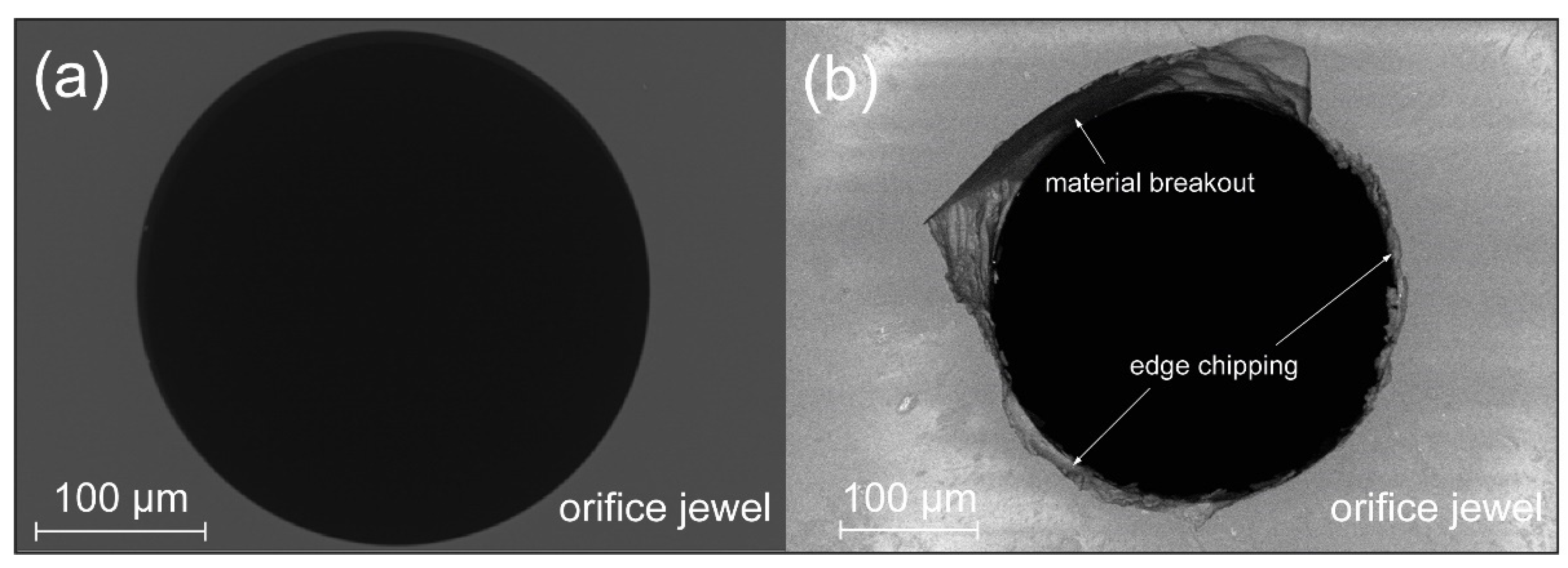
Figure 6 shows images of a virgin and a damaged orifice. After production, the orifices have a very low roundness tolerance (
Figure 6a). The round bore, in conjunction with the sharp edge on the top of the orifice jewel [
23], provides high jet coherence as well as constriction of the jet to a diameter that is below the bore diameter [
36]. On the damaged orifice (
Figure 6b), there are various areas of edge chipping. These occur statistically distributed over the bore circumference with increasing operating time due to material defects, external load, cavitation, or particle impact. The observed damage patterns correlate with data published by other authors, like Hashish [
14], Powell [
13], and Li [
37]. The research by Li proved the general problem of edge chipping at sharp-edged holes in ceramic materials, while Hashish and Powell connect this type of failure to the coherence of the water jet. However, they do not provide evidence for the mechanisms, leading to these material breakouts. For early premature failure, it is very likely that particle impact caused these damages. If the density of chipped areas in a region is high, it finally results in large material breakouts.
It can be assumed that the edge chipping is the result of cracks propagating in the area near the bore edge. Material defects in the sapphire can serve as the starting point for these cracks, as known from conventional fracture mechanics [
28,
29]. Manufacturing processes cause material defects and they are always present in real materials. However, these material defects are statistically distributed inside the material and between different orifices. Clearly, this does not explain the preferred localized damage nor high variations in service life for apparently similar loading conditions.
A possible cause for variations in service lives is additional crack initiation caused by externally-induced damage. As published by Powell, faulty assembly, particle impact, or cavitation can cause these damages [
13].
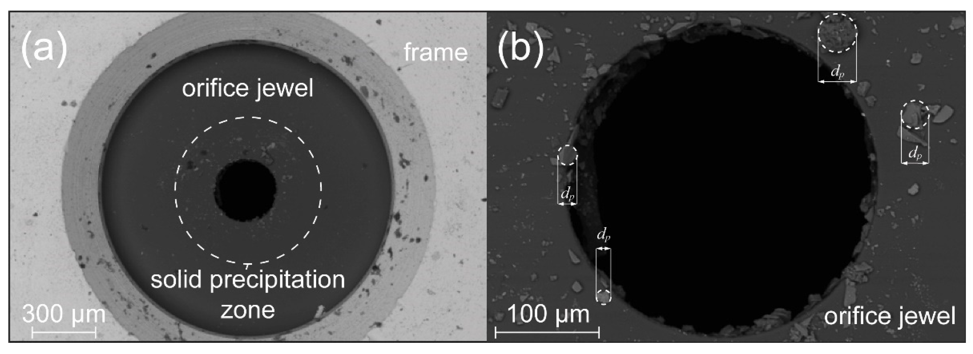
Figure 7 shows particles on the surface of the orifice jewel and at the orifice bore. This observation does clearly support the theory of particles potentially damaging the orifice. Such particles may have their origin in the tap water supplied by the local supplier. In addition, the process water can transport abrasions from other components of the cutting system to the orifice. Another possible source of particles can be traced back to the chemical composition of the process water itself. The process water is not a pure substance but rather serves as a universal solvent for a wide variety of material compounds. These dissolved components may precipitate out of the solution during operation and subsequently have a tribological effect as particles.
Figure 7b demonstrates the influence that particles can have on the orifice jewel, where a larger crack is present on the surface, and a small crack around the orifice bore can be noted. Both cracks have already exceeded the estimated critical crack length of
a ≈ 3.5 µm. However, one must note that this estimate assumes a tensile load, whereas the stress state at a bore is more complex, and a crack can be stopped when compressive stresses prevail.
It was assumed that particles from the process water are the main reason for initiating the cracks in the orifice jewel, as this explains the large variation in service life seen between different operating sites. The fact that precipitates from the water can form on the orifice surface have already been described by Jegaraj et al. [
15]. The authors also suspect a relation between different salt particles and the chipping of the orifice bore’s edge. However, the authors can examine the orifices only after operation. Therefore, only the assumption of the connection of precipitates and orifice damage remains.
Figure 8 shows that, in this study, substantial amounts of particles can also be detected on the jewel for low operation time with more switching operations. As can be seen in
Figure 8a, the particles occur more frequently in the orifice bore area where high fluid velocities are present and less frequently at the outer rim. Thus, it was concluded that particles tend to precipitate out of the solution due to fluid dynamic effects, which can occur due to local cavitation-induced evaporation. In areas such as biotechnology [
38] or the production of nanoparticles [
39], this effect is deliberately utilized. To further investigate the effect of particles on the orifice jewel, their size and their chemical composition was measured, as detailed in the next chapter.
3.2. Particle Analysis
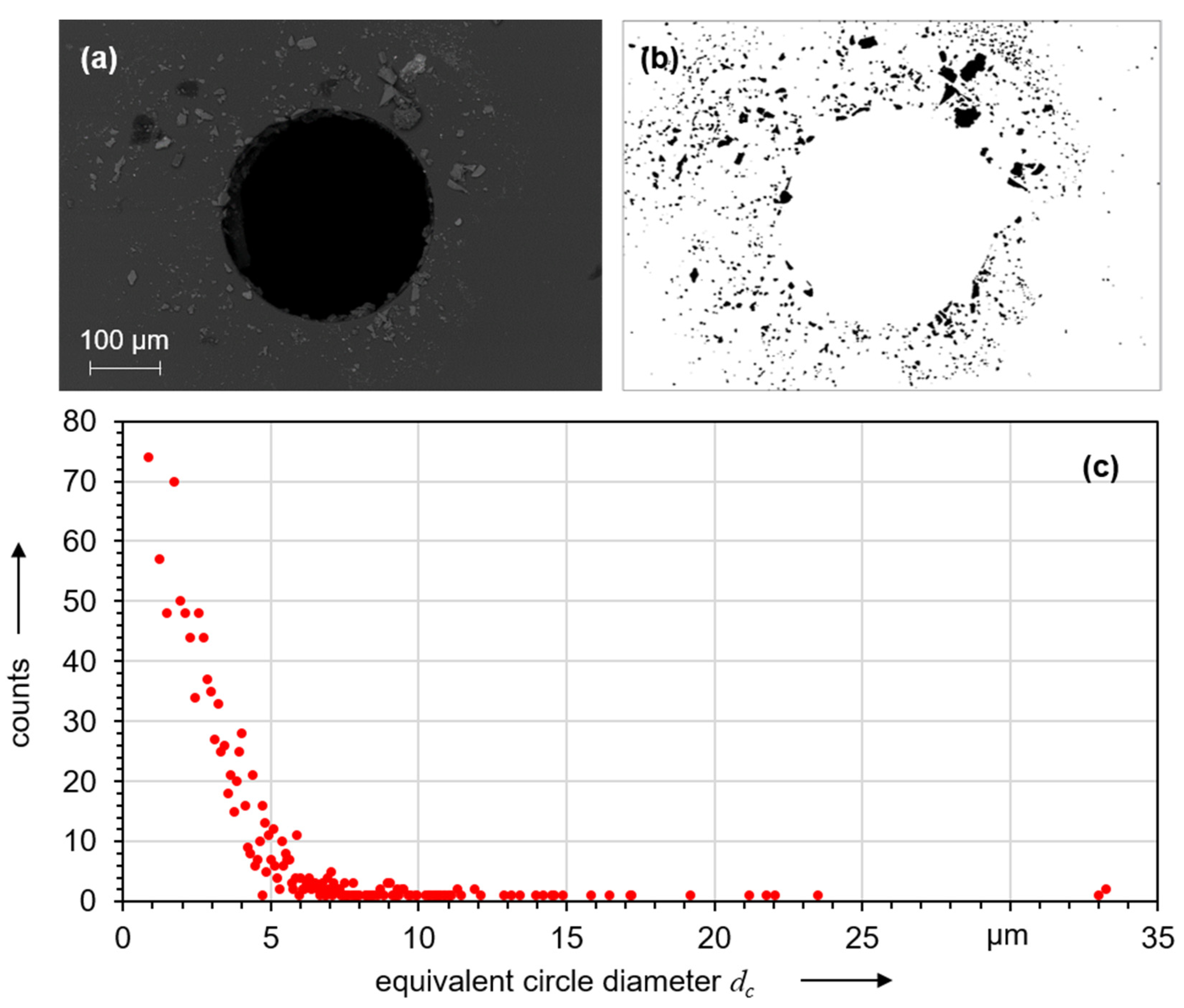
The particle size distribution was determined using digital image processing. The images were processed to obtain binary images (
Figure 9b) using threshold values. Based on the different shapes of the individual particles, the diameter of a circle with the same area was then calculated.
Figure 9c shows the distribution of the diameters of these equivalent circles. For an equivalent diameter below 5 µm, the number of particles increases exponentially. The largest particles observed had an equivalent diameter of 33 µm. Large particles generally have a higher damaging potential, which is why they are also more strongly represented in the remainder of this study. The investigated orifices all originated from a system that had a 5 µm pre-filtration on the pump side. This filtration exceeds the recommendations given in the literature. For example, Wright recommends filtration with a filter mesh size of 10 µm [
25]. Despite the higher quality filtration of the process water, particles can still be found on the orifice jewel. The high number of particles below this filter mesh size can, therefore, be explained as foreign particles. Yet, the particles with equivalent diameters of more than 5 µm have a different origin.
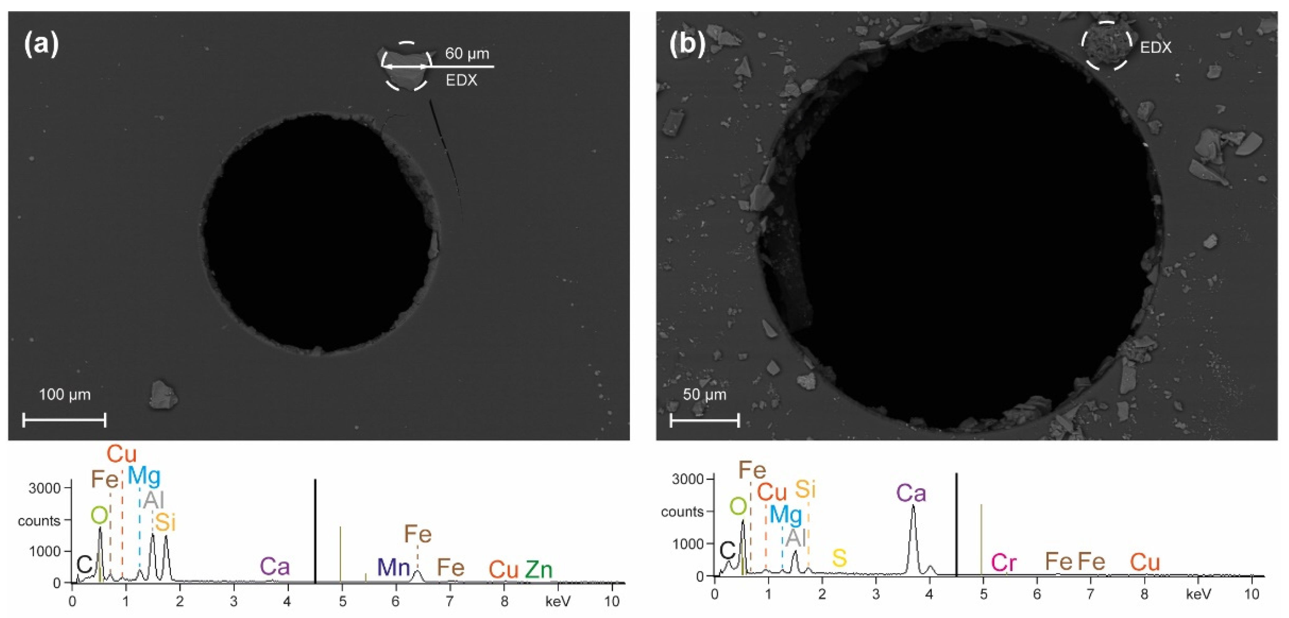
Energy-dispersive analysis of X-rays (EDX) of selected particles was performed to more comprehensively determine the origin and nature of these particles. The analysis in
Figure 10a shows the elements oxygen, aluminum, silicon, and iron and traces of the elements copper, calcium, magnesium, and zinc. It should be noted that light elements are difficult to quantify with EDX. Still, the element composition demonstrates that the investigated particles had their origin in the tap water itself, i.e., all elements detected occur dissolved in the tap water. Specifically, the major element silicon should not originate from the pump, piping system, or other plant components. The element aluminum is the main component of the orifice sapphire itself and is thus present upon analysis of thin particles. The element iron is contained in almost all components of the water jet cutting system and can pass into the tap water dissolved or as abrasion.
Although EDX can only be used to determine elemental compositions and not molecular structures or chemical compounds, further conclusions can still be drawn based on known chemical–physical relationships. For example, the presence of silicon indicates the formation of a silicate particle. It is known that silicates can exist dissolved in water and that their solubility is pressure-dependent [
40]. In conjunction with the other elements detected, it is concluded that the present particle consists of an iron–aluminum silicate (Fe
3Al
2[SiO
4]
3).
Analysis of other particles showed similar chemical composition. However, the proportion of trace elements that can no longer be clearly identified increased in the case shown in
Figure 10b. In this case, the strongest EDX signal was obtained for the element calcium, and the particle is assumed to be of calcium carbonate (CaCO
3) type. This assumption appears valid as calcium carbonate occurs as a solid that is present in almost all water-bearing systems.
Based on the EDX analysis, all particles were assumed to be calcium carbonate or iron–aluminum silicates in the numerical analysis. These two particles have different chemical–physical properties. Specifically, the mechanical properties of the iron–aluminum silicate almandine and the calcium carbonate calcite were used for further numerical investigations.
3.3. Numerical Calculations
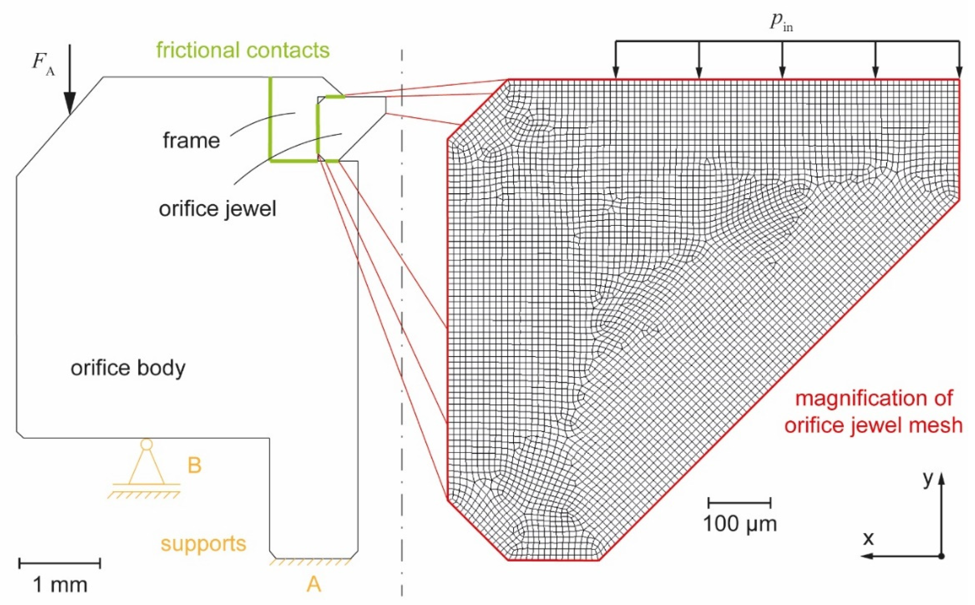
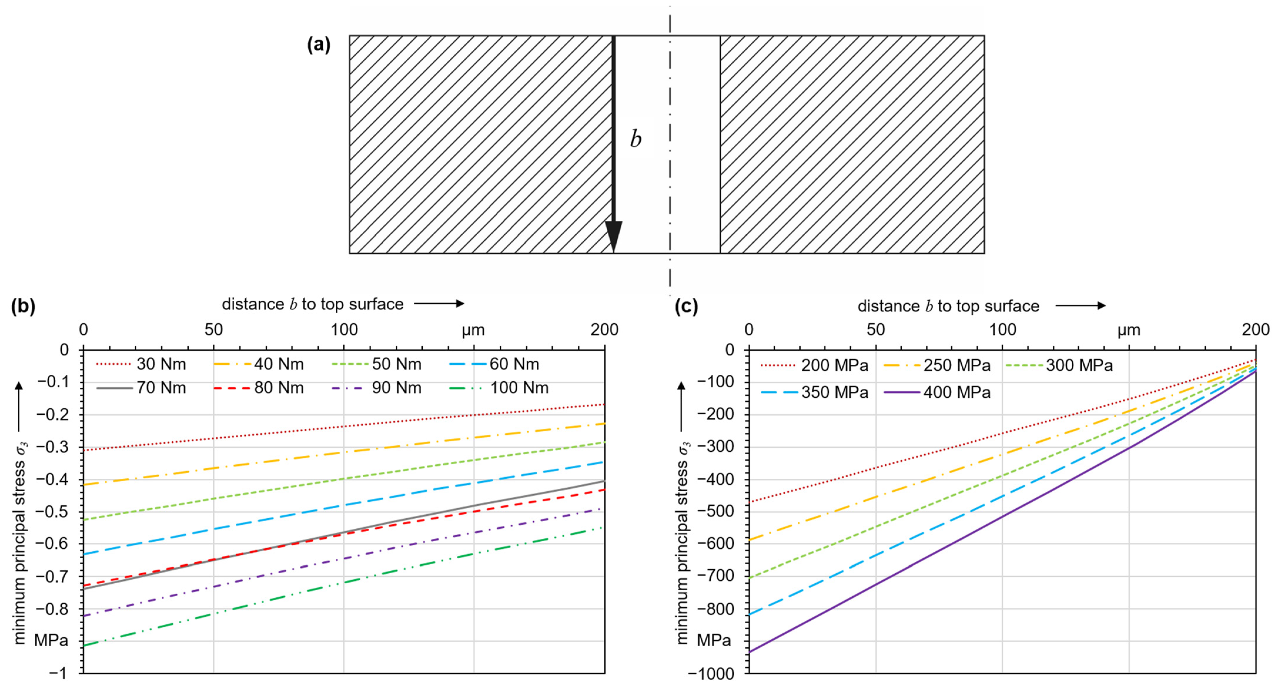
For brittle materials like sapphire, fracture occurs due to a separation normal to the maximum principal stress for a given multiaxial stress state. Already the assembly of an orifice in the water jet cutting system establishes a stress state, and
Figure 11a shows the effect that different tightening torques have on the main stress in the orifice jewel. The curves shown in
Figure 11a are for tightening torques of 30 to 100 Nm. The compressive strength of sapphire is
σc = 2 GPa, whereas the tensile strength,
σt, is only about 200 MPa [
27]. Along the orifice bore, only compressive stresses are present. They exhibit a local maximum directly at the edge of the orifice bore and decrease with increasing distance from the top surface. By convention, compressive stresses are plotted negatively, so the compressive stress with the highest magnitude is equal to the minimum principal stress. Higher tightening torques lead to higher compressive stress, but they are about three orders of magnitude lower than the material strength. The calculated stresses due to assembly are negligible, and thus it is extremely unlikely that a tightening torque exceeding the specification by a reasonable amount will lead to damage to the orifice jewel.
Figure 11b shows the stresses after assembly with a tightening torque of 70 Nm under operating pressures between 200 and 400 MPa. Still, the local maximum is present at the upper edge of the orifice bore, but the magnitudes of the induced stresses are higher by factors between 5 ∙ 10
2 and 10
3 compared with the unpressurized state. Clearly, the stress state is by far dominated by the operating conditions, whereas initial tightening has only a minor effect.
The stress field caused by the operating pressure will slightly oscillate due to fluctuations occurring from the operation of the pump. When using a hydraulic pressure intensifier, these fluctuations are approximately in the range of ±1% of the nominal pressure [
41]. Therefore, these fluctuations are neglected in the following, as fatigue limits in ceramics tend to be close to monotonic strength values.
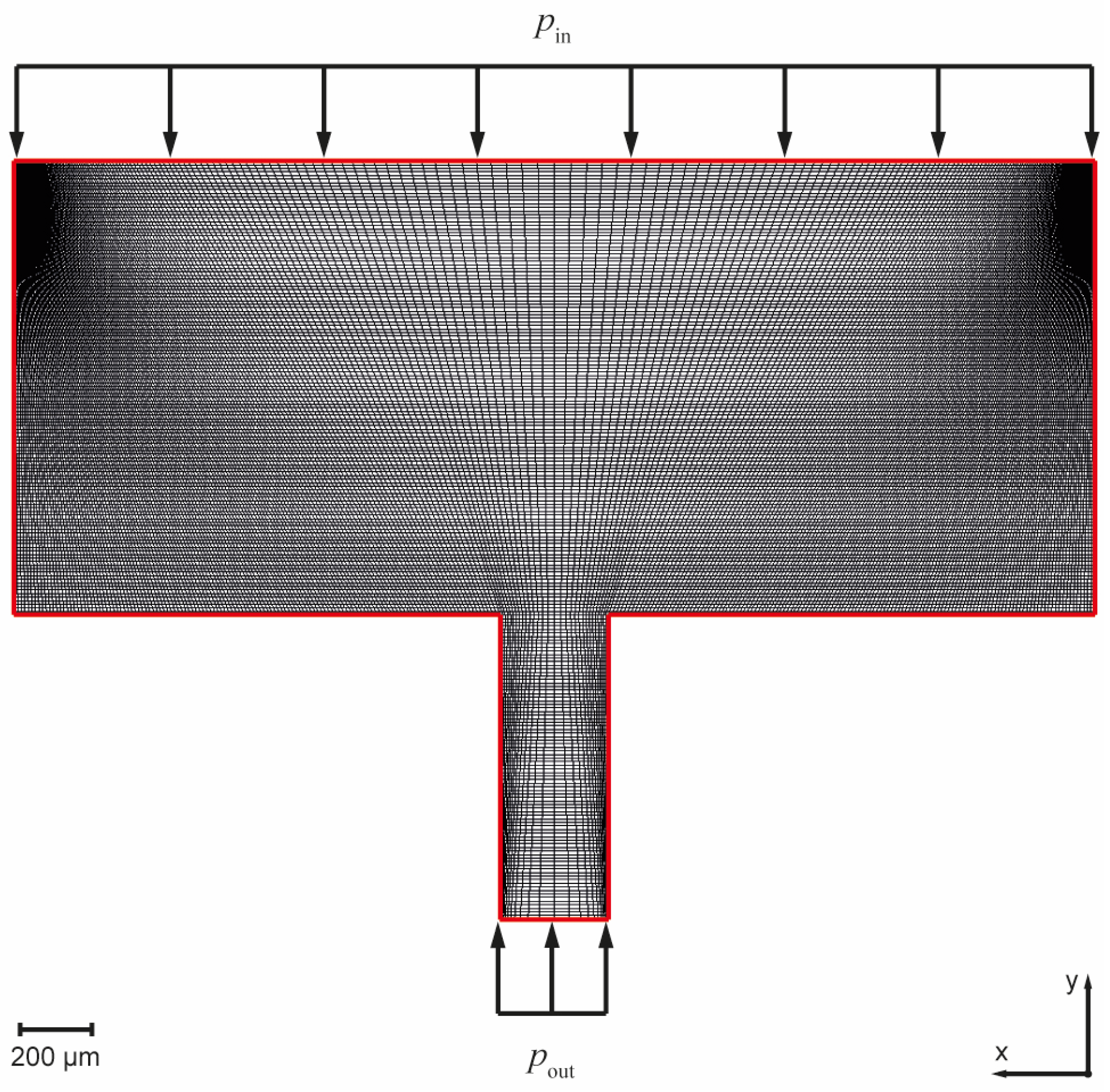
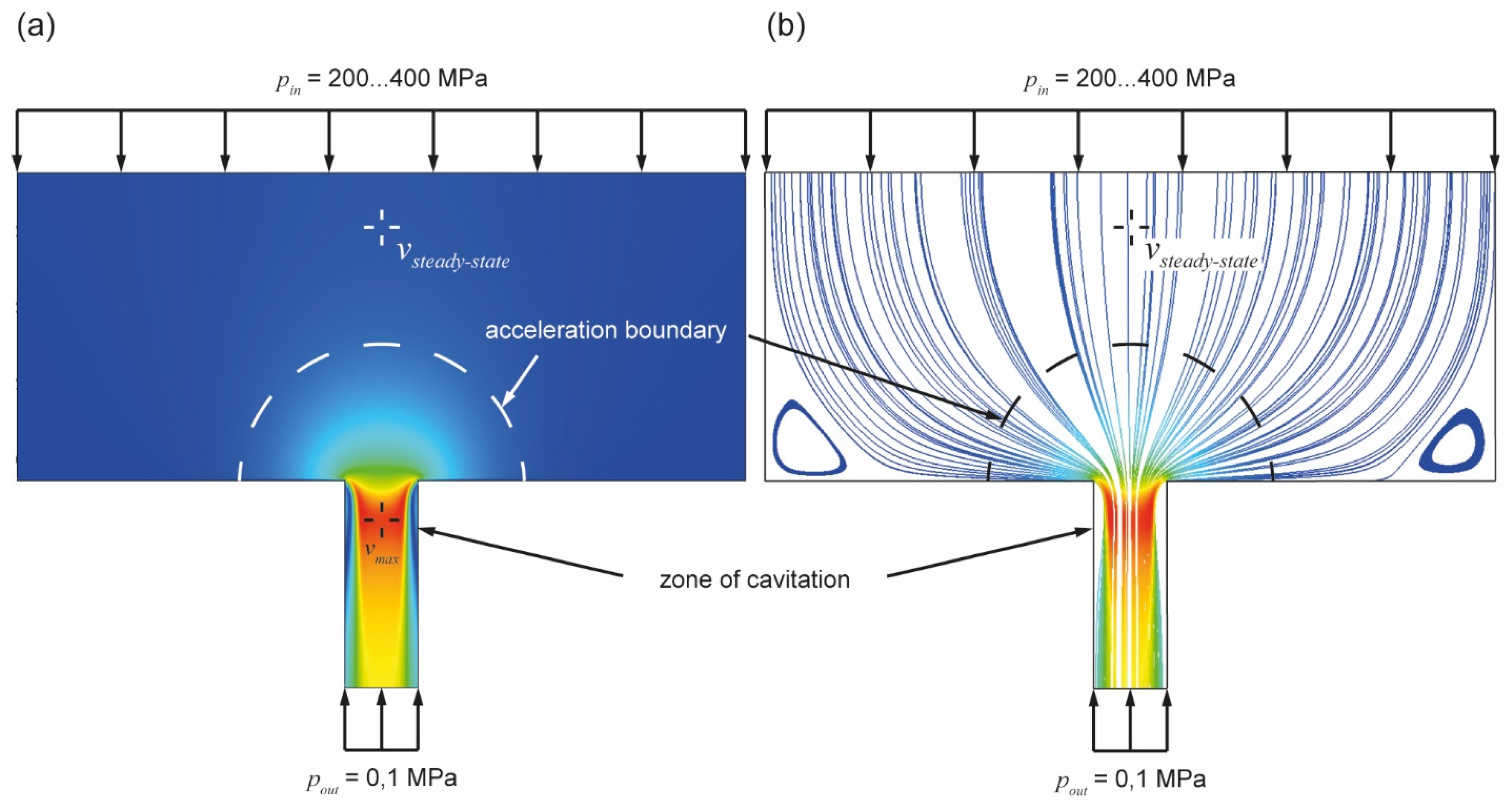
Upon impact, particles transported in the water can locally change the state of stress resulting from the operating pressure. Particles cause short-time discontinuous effects during operation. Particles follow the direction of the water flow through the orifice. For the modeling of the interactions of particles and the orifice jewel, the characteristics of the flow field around the orifice bore were obtained from numerical simulation. The flow field for operating pressures between 200 and 400 MPa was modeled as a steady-state one, i.e., it represents the condition in operation of a water jet cutting system after a sufficiently long time after actuating the pump and cutting valve.
Figure 12a shows a representation of the flow field, where the velocity data are normalized with respect to the maximum value. The direction of the flow field vectors is shown by the representation of the streamlines in
Figure 12b. At a larger distance from the orifice bore, the flow velocity in the collimation tube changes only slightly over the cross-section, and this value is referred to as the steady-state velocity. In the area around the edge of the orifice bore, a strong acceleration of the flow occurs due to the cross-sectional constriction. In addition to the magnitude, the direction of the velocity vectors of the flow field also changes drastically near the orifice bore. These results are in accord with the studies of Annoni [
42], Basha et al. [
24], and Urazmetov [
16]. Basha et al. also observed the constriction of the water jet inside the orifice bore because of zones of cavitation. Additionally, the calculated flow velocities correlate with the author’s results [
24]. The calculated velocity profile of Annoni et al. also matched the results presented in this paper [
42]. Differences occur because of their slightly different orifice geometry, but they can be neglected as they are present at the orifice bore exit, which is not taken into account within the context of this study. The results of Urazmetov et al. [
16] match the results of Annoni et al. [
42] very well and correlate with this study as well. The flow field calculations can therefore be considered as valid.
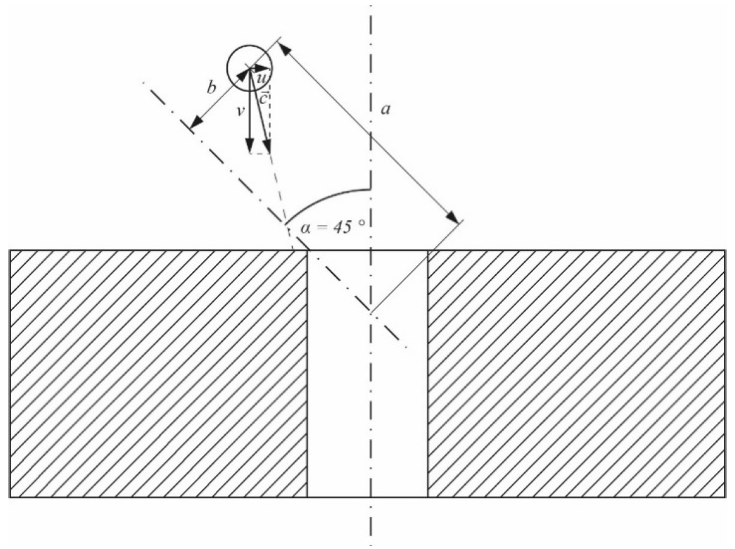
Given the velocity gradient and the deflection of the flow in the acceleration zone, individual particles can continue their trajectory and impact the orifice jewel. In
Figure 13, a point of the flow field is shown where it can be assumed that the impact of the particle on the orifice jewel occurs with a high normal component, and thus, a high damage potential.
The magnitude and direction of the velocity vectors for the critical particle position differ depending on the pressurization of the system. The components of the vectors at different operating pressures are shown in
Table 4.
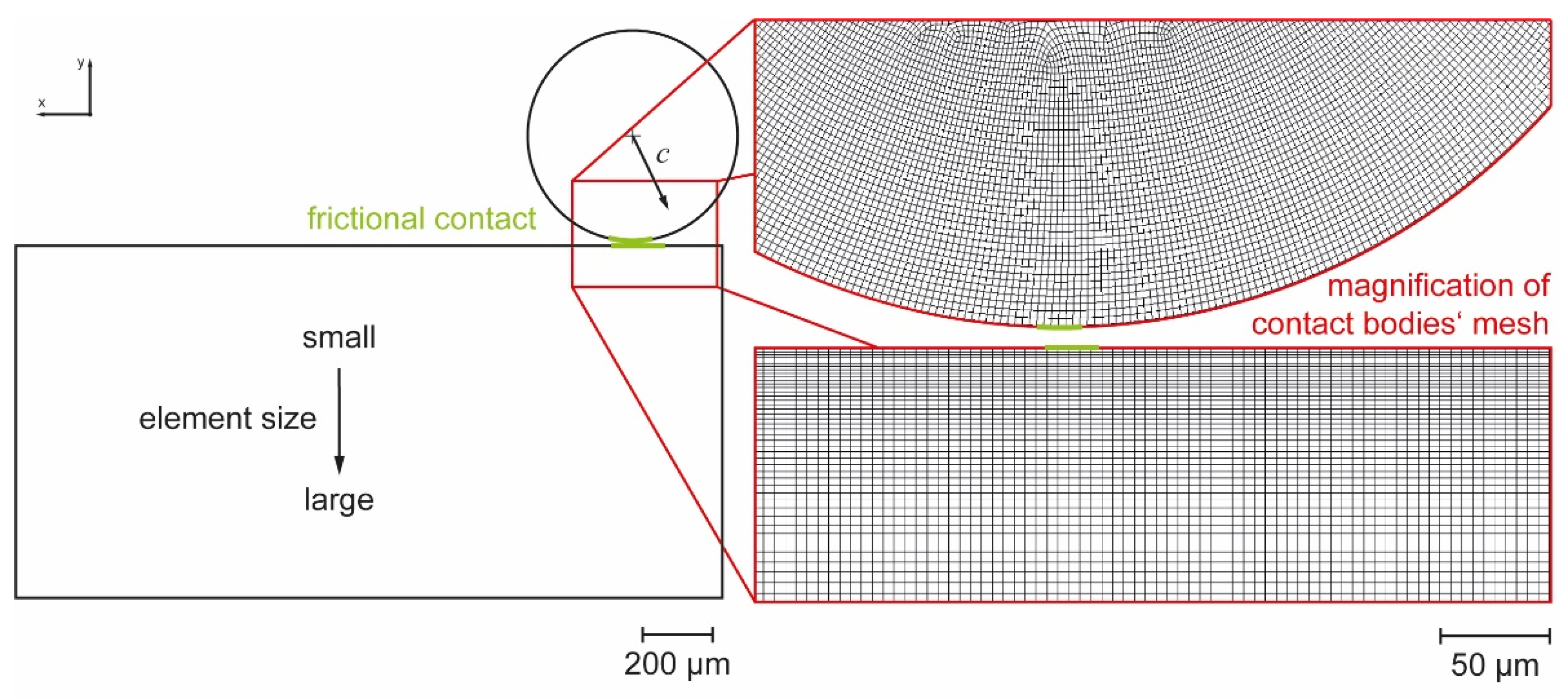
For each operating pressure, particles with diameters between 5 and 60 µm consisting of the two observed materials, calcium carbonate and iron–aluminum silicate, were modeled. The parameter selection covers a wide range of experimentally observed particles without excessively increasing the computational effort. The computational effort was further reduced by utilizing axis symmetry and setting up the simulation in a 2-dimensional space. Additionally, the movement of the individual particles was kept to a minimum before contact. With this approach, a runtime of 36 min was realized on average for each case.
Because of the dynamics of particle impact, the stress state is time-dependent. Principal stresses with high magnitudes can arise when the particle contacts the orifice jewel’s surface. In the following, the maximum and the minimum principal stresses are considered. In the described case of particle impact on an orifice jewel’s surface, these represent the maximum tensile and the maximum compressive stresses, respectively, in the principal coordinate system. Taking the time dependence of the load during particle impact into account, a shift between the maximum tensile stress (temporal maximum of maximum principal stress) and the maximum compressive stress (temporal minimum of minimum principal stress) occurs.
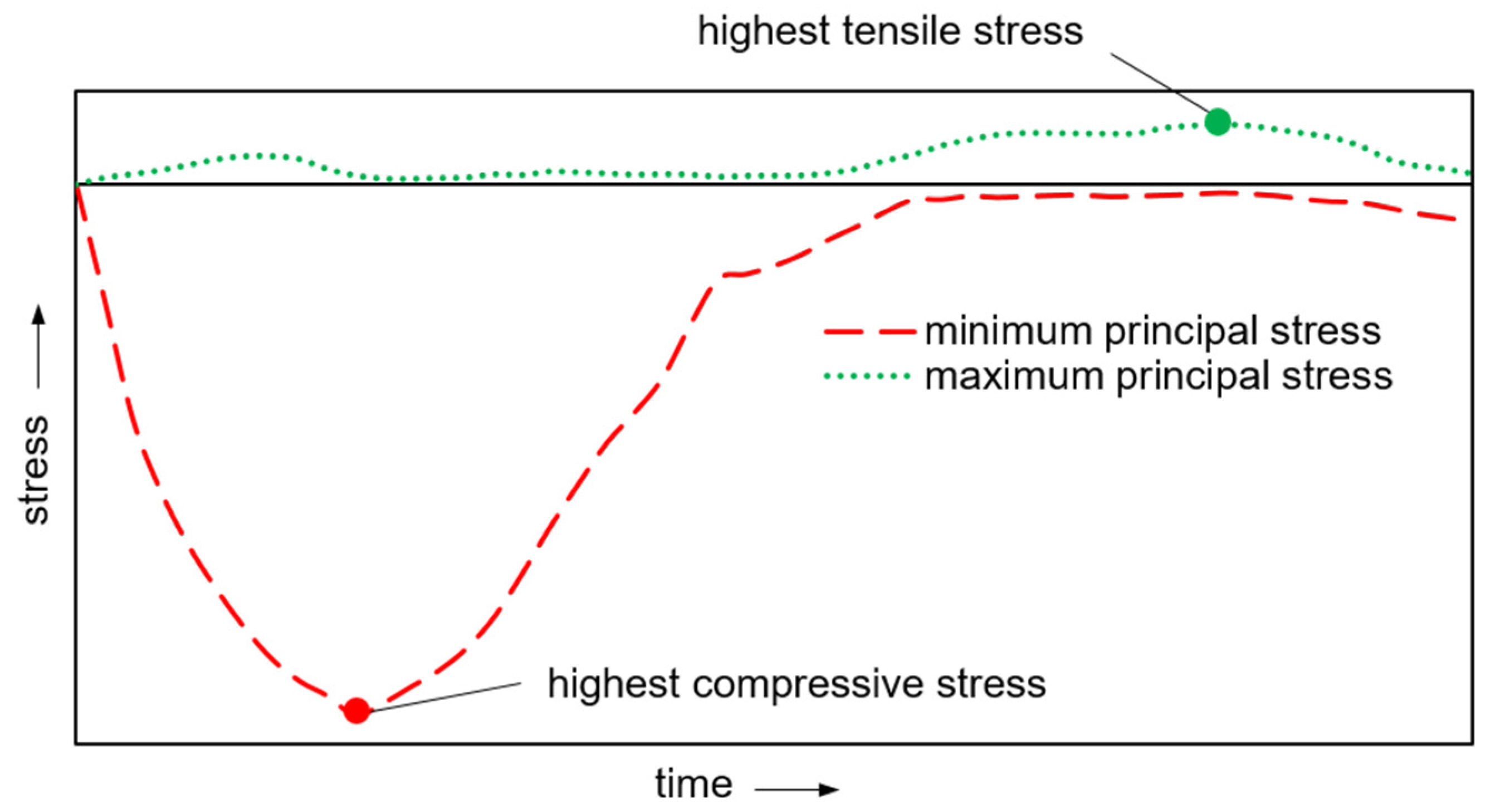
Figure 14 qualitatively shows the induced stress at particle impact over time. For further investigation, the time points with the respective highest magnitude of tensile and compressive stresses were determined, as it was not known a priori which stress state is critical for failure. The two maxima occur at different times so that both principal stresses never have their maximum value at the same time.
The stresses caused by a particle impact depend on particle diameter, operating pressure, and particle material. For evaluating a particle’s damage potential, the modified-Mohr failure criterion was employed. The criterion is widely used to predict the failure of brittle materials and fits experimental data better than the Coulomb–Mohr criterion, even though it is less conservative [
43].
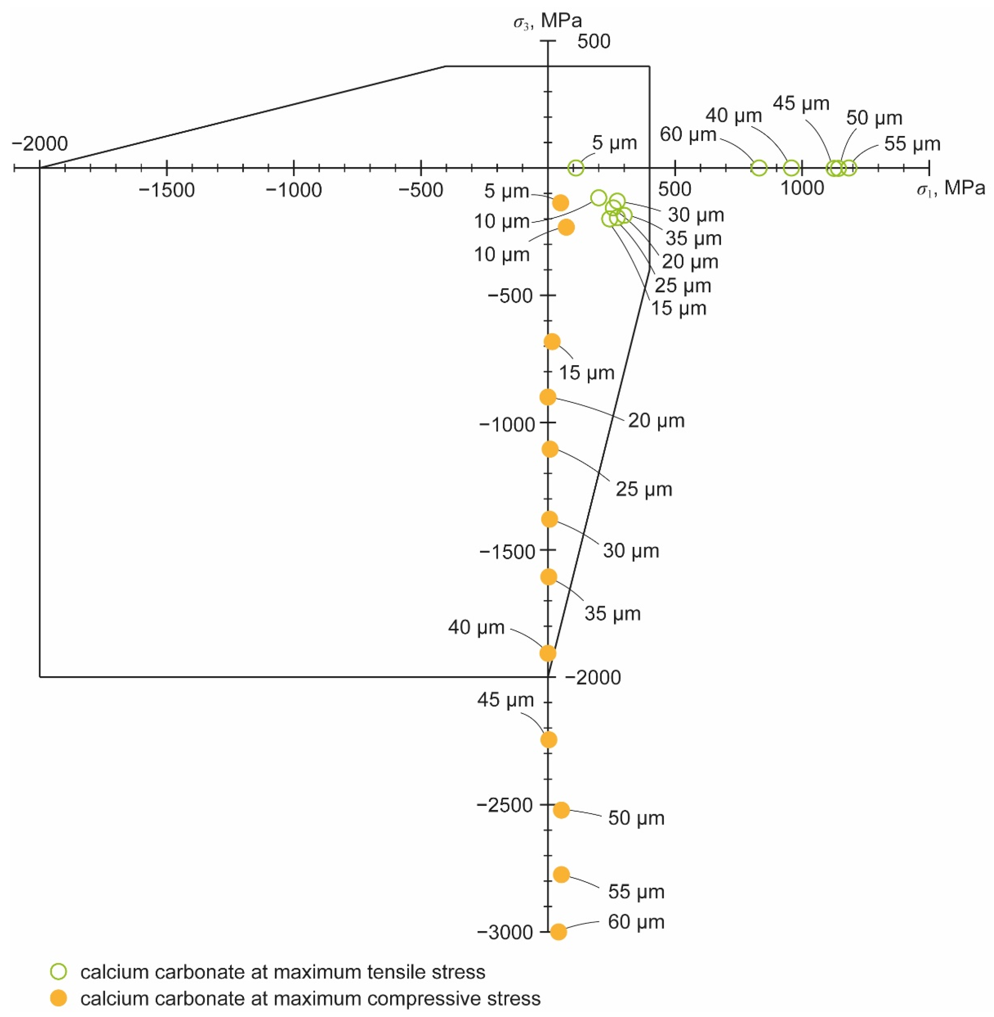
Figure 15 shows the failure envelope obtained for the stresses caused by the impact of calcium carbonate particles of different diameters at 300 MPa operating pressure. The diagram illustrates the position of the principal stresses in relation to the mechanical strength of the material. Damage to the orifice jewel occurs as soon as a point lies outside the failure envelope. These loads, which exceed the material strength, then result in initial damage to the surface during operation, which in turn is the starting point for further crack growth and can lead to the final failure of the orifice.
For the carbonate particles at an operating pressure of 300 MPa, the limit of acceptable particle size appears to be around 30 µm. At this diameter, the principal stress is not yet outside the envelope at the moment of either the greatest tensile or the greatest compressive stress. With a particle diameter of 40 µm, the third principal stress at the moment of the highest compressive stress is still inside, but the first principal stress at the moment of the highest tensile stress is outside the envelope. Next, for particle diameters of 30 µm and below and an operating pressure of 300 MPa, silicate particles of the same diameters were added.
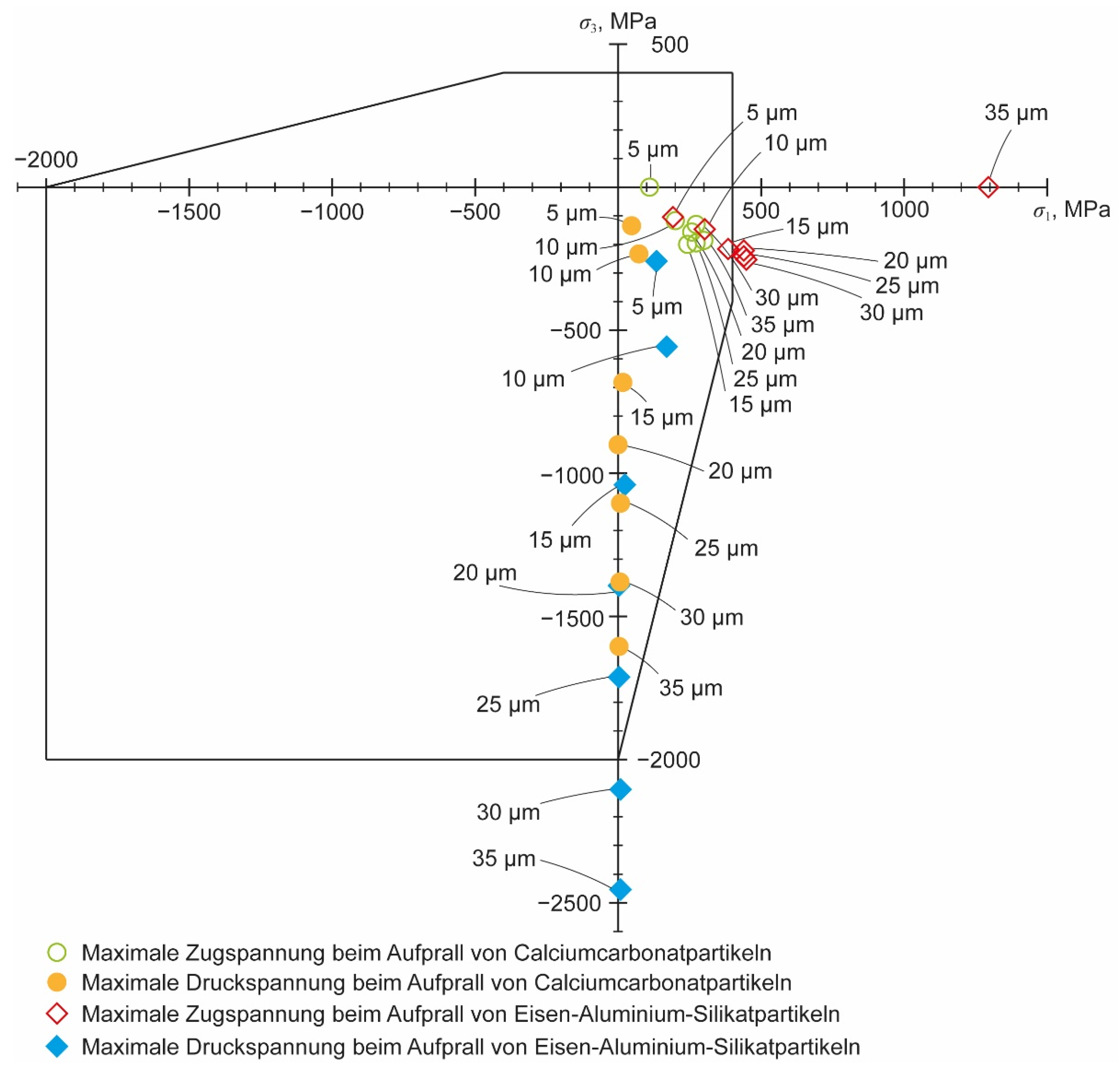
Figure 16 shows the increased damaging potential of the particle assembly. The silicate particles have a higher damaging potential, so the critical particle diameter has now dropped to 15 µm. As with the impact of the carbonate particle, failure also occurs in the bore due to tensile stresses when a silicate particle impacts. The diagram clearly shows that for the same particle diameter, there is a much larger safety factor in the region of compressive stresses. Considering only the moment of greatest compressive stress, the critical particle diameter would not be 15 µm but 25 µm. In essence, crack initiation due to particle impact can occur because of the high induced tensile stresses with silicate particles having the higher damage potential. Therefore, when considering the pressure dependence, only these stresses resulting from the impact of silicate particles are plotted in the remainder of this paper.
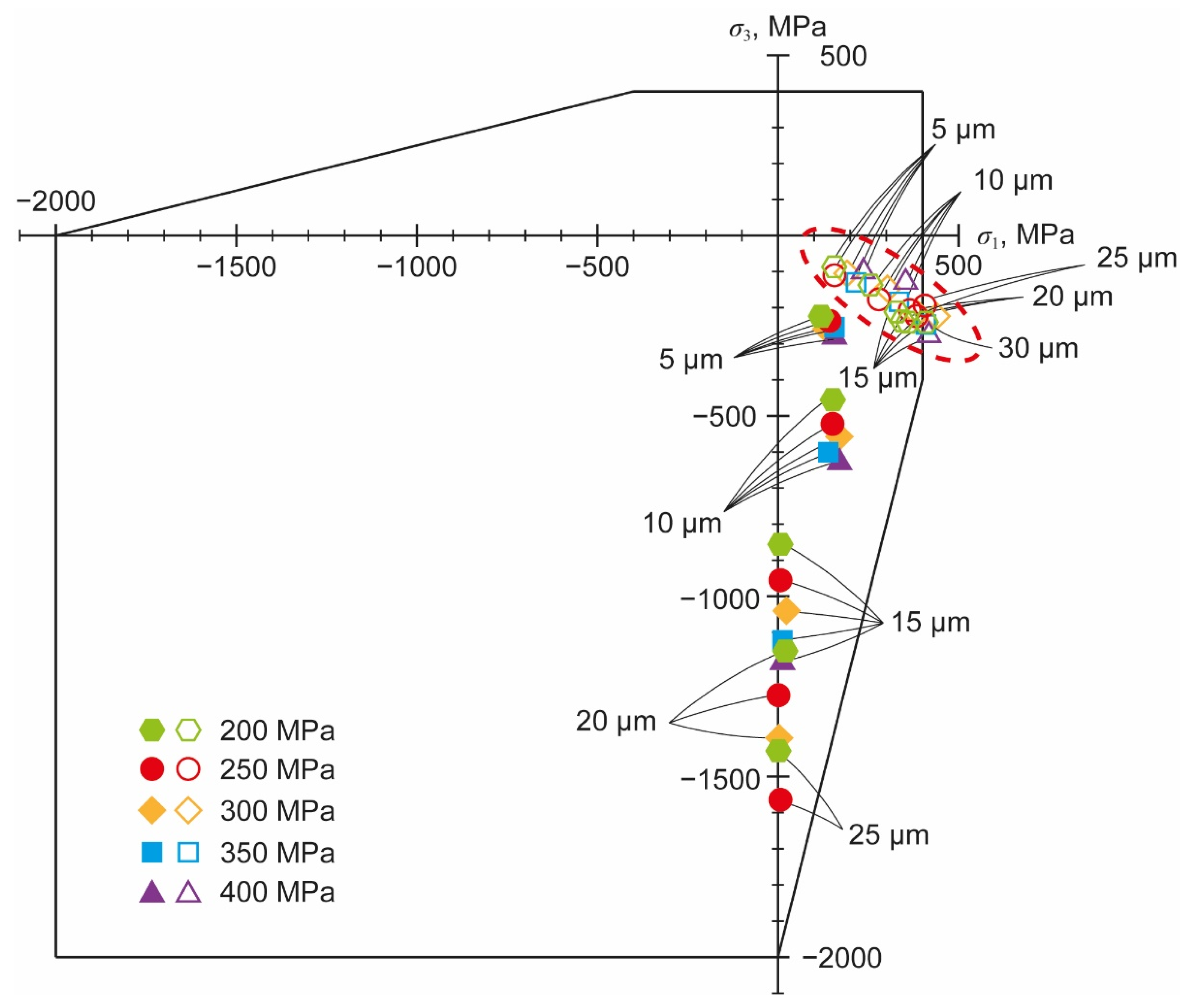
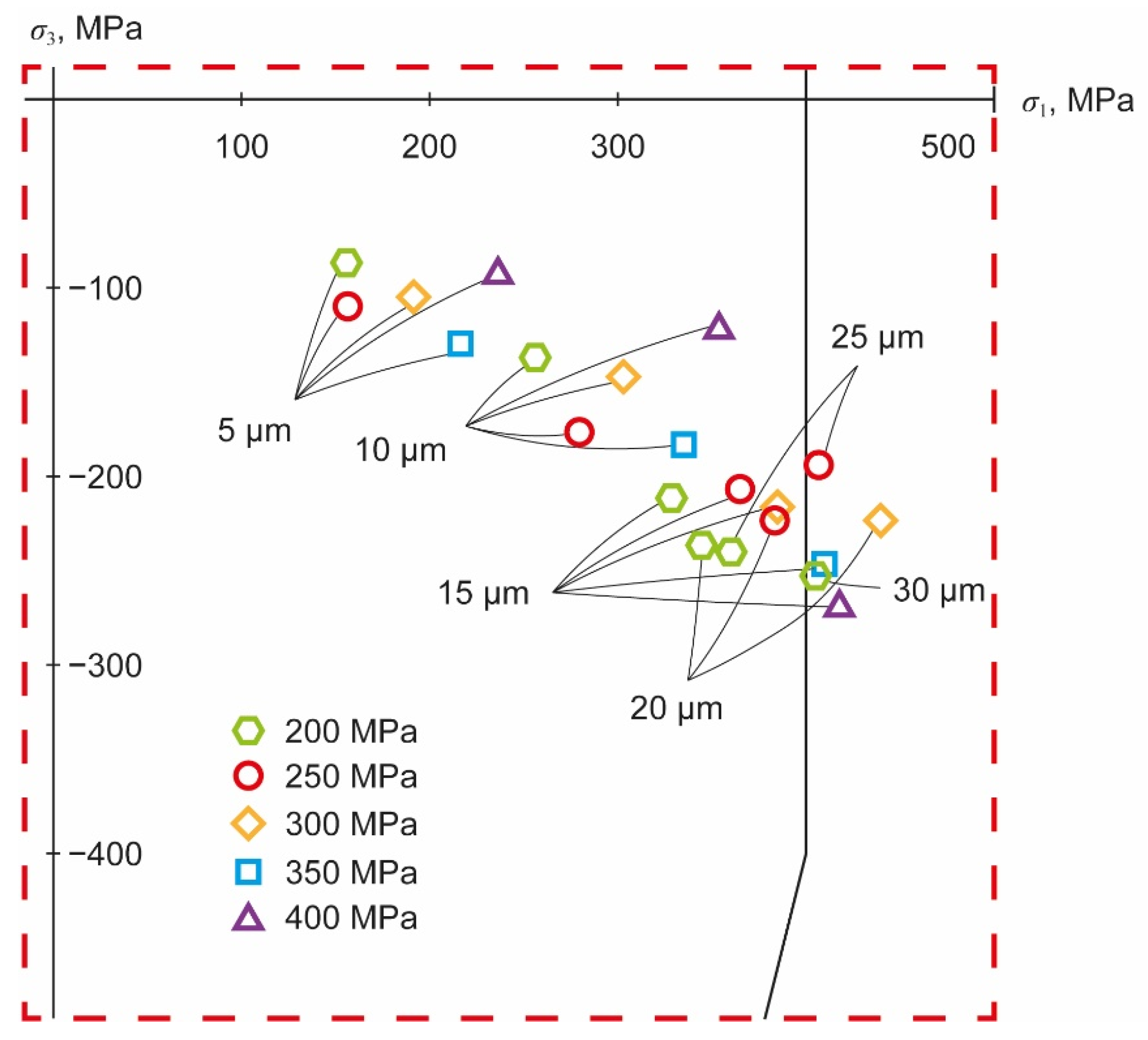
Figure 17 shows the dependence of principal stresses on the operating pressure, and only the stresses caused by the more damaging silicate particles are plotted.
To determine the critical particle diameters,
Figure 18 shows a magnification of the dashed area outlined in
Figure 17. In
Figure 18, only the principal stresses at the moment of the largest tensile stress are given. Considering the different operating pressures investigated, the critical particle diameter varies from 25 µm at 200 MPa to 10 µm at 400 MPa. Silicate particles with diameters as small as 10 µm can therefore contribute to the initiation of cracks in the orifice jewel. This accords with the empiric observations and the recommendations for filtration that are given in the literature. Orifice testing leads to the recommendation of a 10 µm filtration, as stated by Wright [
25]. Taking the results shown in
Figure 18 into account, the assumption seems to be valid. Even if earlier studies did not differentiate between different types of particles and did not look into their origin, it is plausible that their experiment contained silicate particles that did have the same damaging potential as the particles in this study.
Clearly, the effect of an impacting particle on service life of an orifice depends on the operating pressure as well. A reduction in the operating pressure leads to an increase in the critical diameter. An increase of operating pressure, on the other hand, would place increased demands on the particle-free nature of the water. Momber published that a filter mesh size of 10 µm is already mandatory for operating pressures above 100 MPa and that the manufacturer’s recommendations should be applied to further increase operating pressure [
44].
Even if the details of the interaction of individual particles with the orifice jewel surface were not modeled, the damaging effect of particles on orifices is clear. The impact of particles induces stress in the region of the orifice bore, which locally leads to material failure, i.e., initiation of cracks in the sapphire. High loads are particularly critical in the orifice bore since, in additional to the operating pressure, loads are expected there due to the flowing fluid because of the quasi-stationary state of cavitation. The presence of cavitation load is proven by many authors, such as Hashish [
14], Annoni et al. [
42], Basha et al. [
24], and Urazmetov et al. [
16]. Additional stresses due to mounting and alignment, mentioned by Powell [
13], can not be confirmed within this study.
Stresses due to particle impact and cavitation may coincide with damage sites seen in worn orifices obtained in this study. The damage sites also correlate with the damage sites observed by other authors, like Jegaraj et al. [
15] and Li et al. [
37]. It is possible that crack growth starts from the orifice bore and progresses to the orifice jewel surface. Even without cavitation, the present results already demonstrate the presence of critical stress for the usual operating pressure of 300 MPa with common carbonate particles with a diameter of 40 µm. Other substances, such as silicates, which are present in almost all process waters, can cause damage even at smaller particle diameters of 15 µm under these conditions. Increasing the operating pressure further decreases the critical particle size. This result has led to the recommendation of a 10 µm filtration in the past [
25].
Adding the factor of additional loads and assuming that the discontinuous loads from particle impacts and cavitation are equal, a safety factor of S ≥ 2 would be required considering the particle diameter. According to the modified-Mohr failure envelope, this leads to a maximum tolerable particle size of about 5 µm at the maximum operating pressure of 400 MPa.
With regard to foreign particles, this boundary condition is satisfied today in most modern water jet cutting systems by sufficiently fine pre-filtering. Taking the load resulting from the pressurization of the orifice due to the operating pressure into account, an additional stress of more than 900 MPa affects the bore edge at an operating pressure of 400 MPa. Since this additional compressive stress results in a shift in the modified-Mohr diagram in the negative y direction, the stresses are then outside the failure envelope for a particle diameter of more than 5 µm. By adding the assumed cavitation safety factor, this leads to a need for a pre-filtering with a mesh of 2 µm or less.
Other studies give different recommendations for filtering high-pressure water. Wright [
25] recommends a filter mesh size of 10 µm for waterjet cutting, whereas Momber [
44] suggests 25 µm. Even if the given recommendations seemed to be valid without taking additional loads into account, it can be shown that the safety margin was very low. As these studies were made almost two decades ago and there have been no other recommendations so far, these large values may explain the fluctuations in orifice service life observed in practice. Thus, this study provides new data for a better understanding of the water treatment required in waterjet cutting to reduce premature orifice failure.
The present study also showed the range of particles precipitating from the water during operation, which filtering of the tap water cannot prevent. Commercially available filters allow filter mesh sizes around 1 µm. However, high-pressure filters can only be installed at some distance in front of the switching valve and the actual cutting head. Thus, there is still a risk of precipitation, especially in the cutting head. The avoidance of these precipitates by physical-chemical or design measures will be of central importance for future high-pressure water cutting systems to increase the service life of the orifices.
