Abstract
In order to study the change law of loss and efficiency of high-speed permanent magnet motor (HSPMM) under load after using FeCo_B800 alloy material instead of silicon steel sheet DW310_35 material to make iron core, two FeCo_B800 stator materials with the same structure and size parameters were developed. HSPMM and HSPMM of silicon steel DW310_35 stator material. The loss and efficiency characteristics of the two motors under the same operating conditions were tested by the experimental method, and the losses of the two motors at different load rates were compared and analyzed by means of the finite element method. The research results show that at light load, the FeCo_B800 motor stator core loss is lower than the DW310_35 silicon steel sheet motor, and the efficiency advantage is very obvious; however, with the increase of the load rate, the FeCo_B800 motor stator core is seriously saturated, resulting in the distortion of the winding magnetomotive force waveform. The loss caused by the harmonics of the winding magnetomotive force is higher than that of the DW310_35 silicon steel sheet motor, and the efficiency advantage of the FeCo-B800 motor gradually decreases with the increase of the load rate.
1. Introduction
HSPMM has the advantages of compact structure, high efficiency and high power density, and is suitable for high-speed centrifuges, high-speed compressors, flywheel energy storage and other fields [,,]. And with the development of material technology, FeCo alloy material is more and more used in HSPMM due to its excellent low loss performance. However, after using FeCo alloy material to replace silicon steel material to manufacture the motor stator core, the internal loss structure of the motor made of FeCo alloy material will also undergo serious changes. Therefore, it is of great significance to study the composition of FeCo HSPMM iron loss and its influence on the stator material for the design of FeCo motors.
Many scholars at home and abroad have studied alloy motors with different stator materials and made certain achievements. In ref. [], the author has developed a 250 W alloy asynchronous motor. After the stator is made of alloy materials, iron loss is reduced by 80%. In ref. [], a 4-pole, 500 W small asynchronous motor with alloy 2605SA1 as stator and silicon steel sheet M600 as rotor is used. Comparative analysis and no-load iron loss of silicon steel sheet motor at different frequencies show that the iron loss of alloy motor at different frequencies is half of that of silicon steel sheet motor. In ref. [], A 7.5 kW, 1360 r/min motor is designed. The stator and rotor are made of alloy material, totally 47 kg, 5.44 kg less than M19 silicon steel core, and the motor efficiency reaches 92%. In refs. [,], the author has studied axial flux amorphous permanent magnet motors to improve efficiency and power density by optimizing stator structure. In ref. [], taking a 20 kW and 2500 r/min permanent magnet motor for electric vehicle as an example, the stator core of motor is made by using amorphous alloy instead of silicon steel sheet material. After optimization, the power density of amorphous alloy motor is 45% higher than that of silicon steel sheet motor. In ref. [], taking a 3000 r/min permanent magnet motor as an example, the variation rule of motor loss after using amorphous alloy to replace silicon steel to make motor core is analyzed. The result shows that the loss of replaced amorphous alloy motor and core is reduced by 50%. A 60,000 r/min high speed amorphous permanent magnet motor was manufactured in []. The analysis results show that the efficiency of amorphous alloy motor is higher than 90% in a wide range of motor torque operation range after amorphous alloy material is used. In ref. [], the author studied an axial flux amorphous permanent magnet motor with 7000 r/min. The result shows that the efficiency of the motor increases from 90% to 93.5% by using amorphous alloy material. In ref. [], the author has studied a super-high speed amorphous alloy permanent magnet motor with a maximum speed of 120,000 r/min. The research shows that compared with silicon steel sheet, the rotor made of amorphous alloy can reduce the loss of rotor core material by 82%. In the process of analysis and calculation of the above documents, only the total iron loss value is calculated, but the change rule of iron loss distribution with load rate is lack of in-depth study.
At present, the theoretical research on the loss of FeCo stator material is still in its infancy, and there is no literature to study the loss of FeCo stator material, based on the above research status, this paper uses experiments to test the loss and efficiency of FeCo HSPMM and silicon steel HSPMM under the same operating conditions, and compares and analyzes the experimental results. Variation of wave loss. On this basis, the variation law of the loss of each part of the two motors with the load rate is deeply studied by means of the finite element method.
2. Performance Comparison of FeCo_B800 and Silicon Steel DW310_35 Cores
In the frame of this study, the FeCo motor stator core and the silicon steel motor stator core are made of FeCo_B800 and DW315_50 materials, respectively. The lamination coefficient of FeCo_B800 iron core is 0.88, and the lamination coefficient of silicon steel DW315_50 iron core is 0.97. In order to obtain the magnetization performance and loss performance of FeCo_B800, the magnetization performance and loss curve of FeCo_B800 iron core material at 300 Hz were measured experimentally in this paper. The experimental schematic diagram and circuit diagram are shown in Figure 1 and Figure 2, respectively. The DW315_50 material was compared, and the results are shown in Figure 3, Figure 4 and Figure 5. The thickness of silicon steel sheet DW315_50 is 0.5 mm, and the average thickness of FeCo_B800 is 0.28 mm.
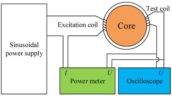
Figure 1.
Schematic diagram of the experiment.
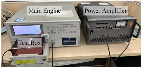
Figure 2.
Experimental setup test.
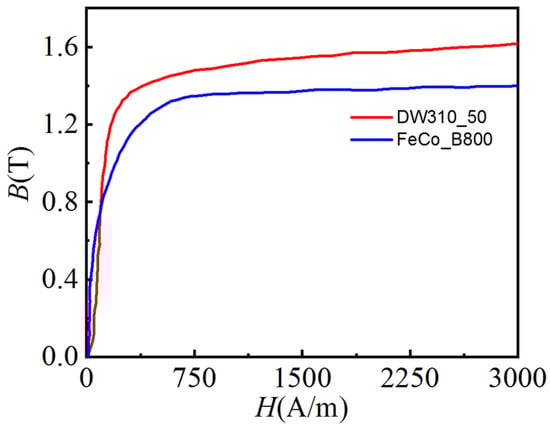
Figure 3.
Comparison of magnetization curves.
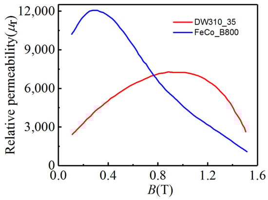
Figure 4.
Comparison of relative permeability curves.
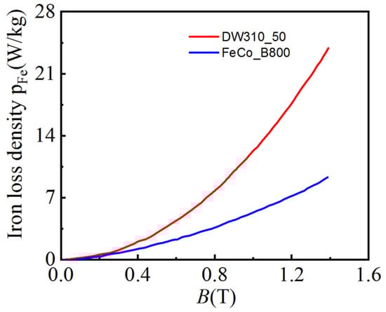
Figure 5.
Comparison of iron loss density curves.
It can be seen from the comparison of the magnetization curves in Figure 1 that the inflection point position and saturation magnetic density of FeCo_B800 iron core are lower than those of silicon steel sheet DW315_50 iron core. It can be seen from the relative magnetic permeability comparison in Figure 4 that the magnetic permeability of FeCo_B800 iron core is higher than that of silicon steel sheet DW315_50 iron core when the magnetic density is low, but within the magnetic density range of iron cores commonly used in motors, the magnetic permeability of FeCo_B800 iron core The rate is lower than that of the silicon steel sheet DW315_50 core. Taking the magnetic flux density B of 1.0 T as an example, the magnetic permeability of the silicon steel sheet DW315_50 is 1.52 times that of the FeCo_B800 iron core. It can be seen from the comparison of loss density curves in Figure 5 that the FeCo_B800 core has a very obvious advantage in loss density. Moreover, taking the magnetic flux density B as 1.0 T as an example, the FeCo_B800 core loss density is only 43.1% of that of the silicon steel sheet DW315_50.
3. Comparison of Efficiency of FeCo Motor and Silicon Steel Motor
Using the above two iron core materials, two FeCo and silicon steel HSPMMs with the same structure and size parameters were fabricated, respectively. The motor adopts distributed short-distance winding, and the total length of permanent magnet is the axial length of the motor, 80 mm.The structure is shown in Figure 6, and the specific parameters of the motor are shown in Table 1.
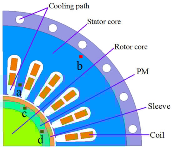
Figure 6.
Structure of HSPMM.

Table 1.
Main parameters of HSPMM.
In order to intuitively analyze the change of the loss and efficiency of the motor after the stator core is made of FeCo_B800 material, the thermal state of the two motors under the power supply of the PWM inverter was tested by the experimental method, and the speed was 18,000 r/min Working characteristics, the experimental platform is shown in Figure 7, the experimental results are analyzed, and the loss and efficiency of the two motors at different load rates are compared, as shown in Figure 8 and Figure 9.
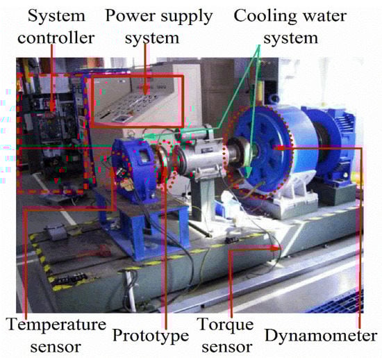
Figure 7.
Prototype experimental platform.
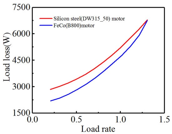
Figure 8.
Load loss comparison curve.
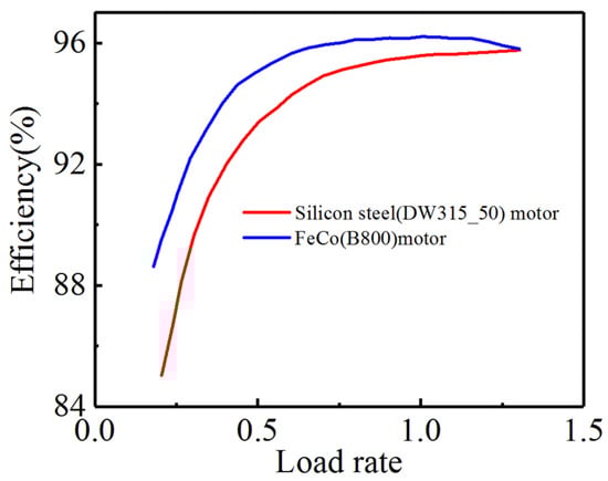
Figure 9.
Efficiency comparison curve.
It can be clearly seen from Figure 8 and Figure 9 that under different load rates, the loss of FeCo motor is lower than that of silicon steel sheet motor, and the efficiency of FeCo motor is higher than that of silicon steel motor. From the changing trends of the curves in Figure 8 and Figure 9, it can be seen that the efficiency of the FeCo motor is significantly improved at light load, but with the increase of the load rate, the loss of the FeCo motor increases significantly faster than that of the silicon steel motor, and its efficiency advantage gradually increases. In order to analyze the reasons for this phenomenon, the motor loss separation method proposed in the literature [] is used to compare and analyze the losses of each part of the two motors at different load rates.
4. Contrastive Analysis of FeCo Motor and Silicon Steel Motor Loss
4.1. Motor Loss Separation Method
Due to the relatively high frequency of high-speed motors, PWM inverters are generally used for power supply [,]. The prototype of this paper was tested experimentally, and the current waveform measured by the experiment was directly used for analysis. Figure 10 shows the FeCo motor at rated load. Line current waveform and its harmonic analysis.
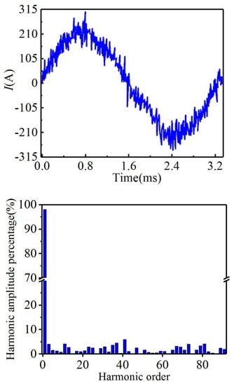
Figure 10.
Current waveform and harmonic components.
The current waveform in Figure 10 is substituted into the finite element method as the excitation source to analyze the high-speed permanent magnet motor model, and the radial and tangential flux density change waveforms of the stator core teeth, yoke and the typical positions on the surface and inside of the permanent magnet are recorded, as shown in Figure 11. The high-speed permanent magnet motor in this study belongs to surface mounted rotor structure; therefore, the loss content in the rotor core is very small, which will be ignored. The harmonic components in the magnetic density waveform of the stator core and permanent magnet can be obtained by Fourier decomposition.
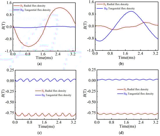
Figure 11.
Magnetic flux density waveforms at points (a–d) on the motor.
For the calculation of stator core loss, the harmonic magnetic densities derived from Fourier decomposition are substituted into Equation (1). Here it is necessary to specify, in particular, the kh in Equation (1). α And ke are obtained by non-linear fitting based on the core loss density test data of FeCo_B800 stator material and the loss density data of DW315_50 silicon steel. The specific values are shown in Table 2.
Table 2.
Loss factor of stator core material.
In the formula: kh and α are the hysteresis loss coefficients; ke is the eddy current loss coefficient; ρs is the material density of the stator core; v is the harmonic order of the magnetic density of the stator core; f is the fundamental frequency; Bvr is the v-th harmonic diameter; Bvθ is the tangential magnetic density component of the v-th harmonic; and vs. is the volume of the stator core.
For the calculation of permanent magnet eddy current loss, according to Maxwell’s equations:
The eddy current in the permanent magnet is solved as:
According to the Poynting vector, the eddy current loss in the permanent magnet is:
In the formula: σ is the conductivity of the permanent magnet; Vm is the volume of the permanent magnet.
4.2. Validation and Analysis of Loss Calculation Results
In this paper, the losses of each part of the FeCo motor and the silicon steel motor at multiple load rates are calculated, respectively. Figure 12 shows the loss of each part of the FeCo motor and the silicon steel motor when the load rate is 0.2 and their comparison with their respective experimental test values. In the figure, ppm1, ppm2 and ppm3 are the permanent magnet loss caused by the harmonic current, the permanent magnet loss caused by the harmonic magnetomotive force of the winding, and the permanent magnet loss caused by the permeance harmonic, respectively; in the figure, pstator1, pstator2, pstator3 and ptest are the experimental values of the stator core loss caused by the fundamental wave, the stator core loss caused by the armature reaction magnetomotive force harmonics, the stator core loss caused by the harmonic current, and the motor loss, respectively. It should be explained that the loss experimental test value in Figure 12 is minus the winding copper loss, air friction loss, carbon fiber sleeve loss and mechanical loss.
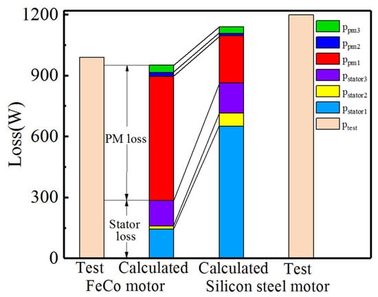
Figure 12.
Motor loss separation and verification.
It can be clearly seen from Figure 12 that the calculated loss values of the two motors are in good agreement with the experimental test values, which indirectly proves the correctness of the motor loss separation method. The excellent loss characteristics make the loss value in the FeCo motor stator core only 32.95% of that of the silicon steel motor, which is why the FeCo motor has an obvious advantage in efficiency at 0.2 times the load. However, the losses caused by harmonics in FeCo motors are significantly higher than those in silicon steel motors, especially the eddy current losses in permanent magnets. The main reason is that the magnetic permeability of FeCo_B800 material in the common magnetic density section of the motor is lower than that of the silicon steel sheet DW315_50 material, as shown in Figure 4. Since the inductance of the FeCo motor is lower than that of the silicon steel motor, when the PWM inverter is used for power supply, the blocking effect of the winding on the high-order carrier harmonic current is obviously weaker than that of the silicon steel motor, which directly leads to a higher harmonic content in the current waveform than the silicon steel motor. This also limits the efficiency advantage of FeCo motors to a certain extent. Further research shows that with the increase of the motor load rate, the loss of each part of the two motors presents a new change law. Figure 13 and Figure 14 show the loss histograms of FeCo motors and silicon steel motors at different load rates.
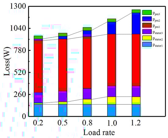
Figure 13.
Loss separation of FeCo motors with different load rates.
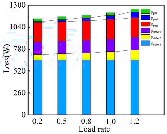
Figure 14.
Loss separation of silicon steel motor at different load rates.
It can be seen from Figure 13 and Figure 14 that with the increase of motor load rate, pstator1, pstator3, ppm1 and ppm3 in FeCo motor and silicon steel motor remain basically unchanged, and the significant loss is caused by the harmonics of the armature reaction magnetomotive force. The stator core losses pstator2 and the permanent magnet losses ppm2 due to the harmonics of the winding magnetomotive force. Comparing Figure 13 and Figure 14, it can be seen that the above two losses of FeCo motor increase with the increase of load rate much larger than that of silicon steel motor, especially the permanent magnet loss ppm2 caused by the harmonics of winding magnetomotive force. From 0.2 times the load to 1.2 times the load, the ppm2 of the FeCo motor increased from 18 W to 252 W, an increase of 14 times, while the ppm2 of the silicon steel motor increased from 11.55 W to 69.3 W, an increase of six times, the pstator2 of the FeCo motor increased from 14 W to 90 W, and the total loss of the FeCo motor increased to 310 W, the pstator2 of the silicon steel motor increased from 65 W to 120 W, the total loss of silicon steel motor increased by 112.75 W.
Figure 15 and Figure 16 compare the distribution of magnetic densities of FeCo motor and silicon steel motor at 0.2 times load and 1.2 times load.
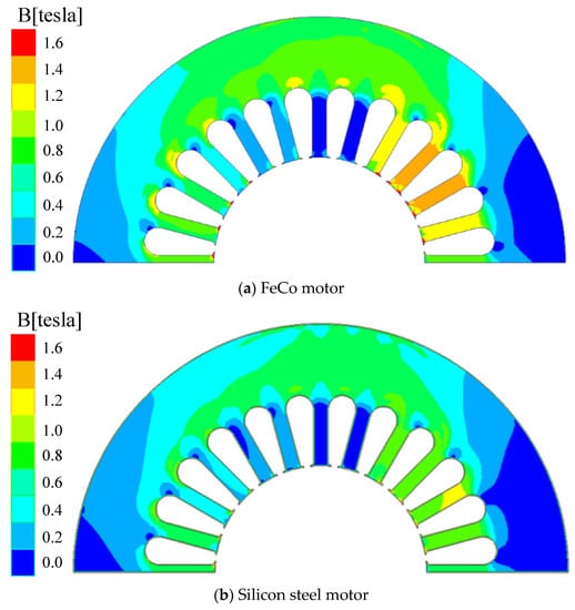
Figure 15.
Comparison of magnetic density at 0.2 times the load.
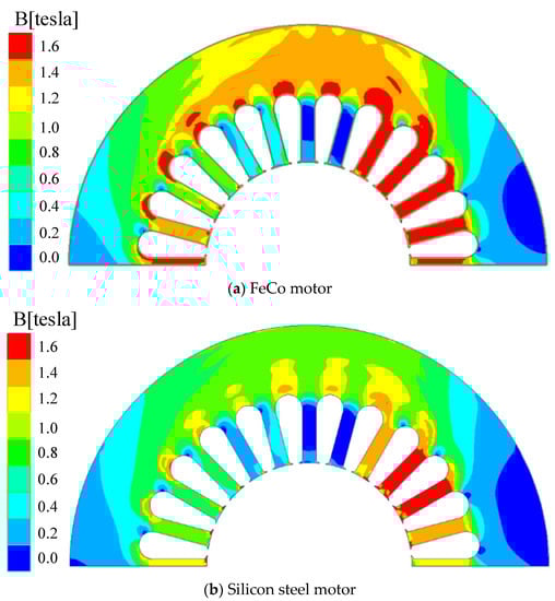
Figure 16.
Comparison of magnetic density at 1.2 times the load.
It can be seen from Figure 15 and Figure 16 that since the lamination coefficient of the FeCo motor iron core is lower than that of the silicon steel motor iron core, the magnetic density of the FeCo motor stator core is much higher than that of the silicon steel motor at 0.2 times the load. Furthermore, the saturation magnetic density of FeCo motor iron core is lower than that of silicon steel motor (Figure 3); therefore, with the increase of load rate, the saturation degree of FeCo motor stator iron core is much higher than that of silicon steel motor, and the FeCo motor winding magnetomotive force waveform distortion is more serious, due to The resulting increase of pstator2 and ppm2 with the increase of load rate is larger than that of silicon steel motor, which indirectly causes the FeCo motor’s efficiency advantage to become smaller and smaller with the increase of load.
5. Conclusions
In this paper, the magnetic properties and loss coefficient of FeCo_B800 stator core material are tested by the method of experimental test, and the experimental results are compared with the material of silicon steel sheet DW315_50. The load loss and efficiency characteristics of two FeCo motors and silicon steel sheet motors with the same structural size are tested. The finite element simulation method is used to analyze the variation law of the loss of each part of the two motors with the load rate, and the following conclusions are drawn:
- (1)
- The saturation magnetic density of FeCo_B800 stator material and the magnetic permeability in the common range of iron core are lower than those of silicon steel DW315_50 stator material, but FeCo_B800 stator iron core has a very obvious advantage of low loss density.
- (2)
- Due to the excellent loss characteristics of FeCo_B800 stator core, the loss of FeCo_B800 stator core is significantly lower than that of silicon steel DW315_50 core at light load, and the efficiency advantage is obvious.
- (3)
- With the increase of the load rate, the FeCo_B800 stator iron core is seriously saturated, and the loss caused by the winding magnetomotive force and armature reaction harmonics is higher than that of the silicon steel motor, which leads to the FeCo motor efficiency advantage gradually decreases with the increase of the load rate.
Author Contributions
Conceptualization, G.L. and G.H.; software, D.T.; formal analysis, D.T. and G.L.; data curation, D.T.; writing—original draft preparation, D.T.; writing—review and editing, P.H. and D.T.; supervision, D.T. and G.H.; funding acquisition, D.T. and G.L. All authors have read and agreed to the published version of the manuscript.
Funding
Open Project of State Key Laboratory of Hydro-power Equipment (SKLHE-ORF-202002).
Institutional Review Board Statement
The study did not involve humans or animals.
Informed Consent Statement
Not applicable.
Data Availability Statement
The study did not report any data.
Conflicts of Interest
The authors declare no conflict of interest.
References
- Hou, P.; Ge, B.; Tao, D.; Pan, B.; Wang, Y. Rotor Strength Analysis of FeCo-Based Permanent Magnet High Speed Motor. Machines 2022, 10, 462. [Google Scholar] [CrossRef]
- Liu, N.-W.; Hung, K.-Y.; Yang, S.-C.; Lee, F.-C.; Liu, C.-J. Design of High-Speed Permanent Magnet Motor Considering Rotor Radial Force and Motor Losses. Energies 2020, 13, 5872. [Google Scholar] [CrossRef]
- Pan, B.; Tao, D.; Ge, B.; Wang, L.; Hou, P. Analysis of Eddy Current Loss of 120-kW High-Speed Permanent Magnet Synchronous Motor. Machines 2022, 10, 346. [Google Scholar] [CrossRef]
- Johnson, L.A.; Cornell, E.P.; Bailey, D.J.; Hegyi, S.M. Application of Low Loss Amorphous Metals in Motors and Transformers. IEEE Power Eng. Rev. 1982, PAS-101, 2109–2114. [Google Scholar]
- Dems, M.; Komeza, K. Performance Characteristics of a High-Speed Energy-Saving Induction Motor with an Amorphous Stator Core. IEEE Trans. Ind. Electron. 2014, 61, 3046–3055. [Google Scholar] [CrossRef]
- Tarımer, I.; Arslan, S.; Güven, M.E. Investigation for Losses of M19 and Amorphous Core Materials Asynchronous Motor by Finite Elements Methods. Elektron. Elektrotech. 2012, 18, 15–18. [Google Scholar] [CrossRef][Green Version]
- Wang, Z.; Masaki, R.; Morinaga, S.; Enomoto, Y.; Itabashi, H.; Ito, M.; Tanigawa, S. Development of an Axial Gap Motor with Amorphous Metal Cores. IEEE Trans. Ind. Appl. 2011, 47, 1293–1299. [Google Scholar] [CrossRef]
- Wang, Z.; Enomoto, Y.; Masaki, R.; Souma, K.; Itabashi, H.; Tanigawa, S. Development of A High Speed Motor Using Amorphous Metal Cores. In Proceedings of the 8th International Conference on Power Electronics—ECCE Asia, Jeju, Korea, 30 May–3 June 2011; IEEE: Piscataway, NJ, USA, 2011; pp. 1940–1945. [Google Scholar]
- Fan, T.; Li, Q.; Wen, X. Development of a High Power Density Motor Made of Amorphous Alloy Cores. IEEE Trans. Ind. Electron. 2014, 61, 4510–4518. [Google Scholar] [CrossRef]
- Okamoto, S.; Denis, N.; Kato, Y.; Ieki, M.; Fujisaki, K. Core Loss Reduction of an Interior Permanent-Magnet Synchronous Motor Using Amorphous Stator Core. IEEE Trans. Ind. Appl. 2016, 52, 2261–2268. [Google Scholar] [CrossRef]
- Kolano, R.; Kolano-Burian, A.; Krykowski, K.; Hetmanczyk, J.; Hreczka, M.; Polak, M.; Szynowski, J. Amorphous Soft Magnetic Core for the Stator of the High-Speed PMBLDC Motor with Half-Open Slots. IEEE Trans. Magn. 2016, 52, 1–5. [Google Scholar] [CrossRef]
- Kahourzade, S.; Ertugrul, N.; Soong, W.L. Loss Analysis and Efficiency Improvement of an Axial-Flux PM Amorphous Magnetic Material Machine. IEEE Trans. Ind. Electron. 2018, 65, 5376–5383. [Google Scholar] [CrossRef]
- Liu, Y.; Ou, J.; Schiefer, M.; Breining, P.; Grilli, F.; Doppelbauer, M. Application of an Amorphous Core to an Ultra-High-Speed Sleeve-Free Interior Permanent-Magnet Rotor. IEEE Trans. Ind. Electron. 2018, 65, 8498–8509. [Google Scholar] [CrossRef]
- Tong, W.; Sun, R.; Zhang, C.; Wu, S.; Tang, R. Loss and Thermal Analysis of a High-Speed Surface-Mounted PMSM with Amorphous Metal Stator Core and Titanium Alloy Rotor Sleeve. IEEE Trans. Magn. 2019, 55, 1–4. [Google Scholar] [CrossRef]
- Tong, W.; Dai, S.; Wu, S.; Tang, R. Performance Comparison Between an Amorphous Metal PMSM and a Silicon Steel PMSM. IEEE Trans. Magn. 2019, 55, 1–5. [Google Scholar] [CrossRef]
Publisher’s Note: MDPI stays neutral with regard to jurisdictional claims in published maps and institutional affiliations. |
© 2022 by the authors. Licensee MDPI, Basel, Switzerland. This article is an open access article distributed under the terms and conditions of the Creative Commons Attribution (CC BY) license (https://creativecommons.org/licenses/by/4.0/).