Article

An Investigation on Dynamic Characteristics of the Straddle-Type Monorail System under Spatial Alignment

1
School of Mechatronics and Vehicle Engineering, Chongqing Jiaotong University, Chongqing 400030, China
2
College of Mechanical Engineering, Zhejiang University of Technology, Hangzhou 310023, China
*
Author to whom correspondence should be addressed.
Machines 2022, 10(9), 724; https://doi.org/10.3390/machines10090724
Submission received: 20 July 2022 / Revised: 17 August 2022 / Accepted: 19 August 2022 / Published: 24 August 2022
(This article belongs to the Section Vehicle Engineering)

Abstract

:
Spatial alignment is a key feature in the design of the straddle-type monorail system (STM), which greatly affects the dynamic characteristics of the STM system. Considering the shear and torsional deformation of the track beam, a new coupling dynamic model of the STM system is established to investigate the dynamic characteristics under spatial alignment. The running safety and the vibration stability of the STM system under different spatial alignments are studied, and the optimal distance between the slope-changing point and the straight-slowing point is determined. Results show that the running safety and vibration stability indices increase when the curve radius decreases and the longitudinal slope gradient soars, and the vibration response of the vehicle is more obvious when the slope-changing points coincide with the transition curve of the track beam compared with that the straight-slowing points do not coincide with the slope-changing points. From the view of running safety and vibration stability, the slope-changing points should not coincide with the transition curve of the track beam, especially with the straight-slowing points. The proposed method can be adopted in the safety design and vibration control of the STM system.

1. Introduction

As a new type of urban rail transit equipment system, the straddle-type monorail (STM) system has become a preferred form of rail transit in small and medium-sized cities and mountain cities because of its capacity for medium carrying and strong climbing, good adaptability to complex terrain and many economic benefits [1]. As one of the difficulties in the STM system safety design and vibration control, spatial alignment is a key feature in the design of the straddle-type monorail of the STM system, which greatly affects the dynamic characteristics of the STM system. Spatial alignment mainly includes plane curves and vertical curves. Unreasonable spatial arrangement parameters would increase the force of tires and aggravate vehicle vibration, not only affecting vehicle safety and passengers’ comfort but also causing traffic accidents. Therefore, it is necessary to study the effect of spatial alignment section characteristics on the dynamic characteristics of the straddle-type monorail system.
Scholars have done some research on the dynamic characteristics of the STM system. Goda [2] established a 15-degree-of-freedom vehicle model to simulate and analyze the curve passing characteristics of monorail vehicles. Based on the buoyancy theory, Zhang [3] studied the influence of the pre-pressure on the running characteristics of the vehicle while passing through curves with different radii and proposed a method to determine the pre-pressure’s magnitude of the guiding wheel and stable wheel. Combining the actual construction of the Chongqing rail transit line with the multi-body dynamic FEA model, Du [4] established the model of the straddle-type monorail vehicle and simulated and optimized the dynamic characteristics of the STM vehicle. Gou [5] studied the dynamic response and ride comfort of STM vehicles based on the multi-rigid body theory. Naeimi [6,7] and Wang [8] established an STM dynamic model coupling vehicle with a track beam to analyze the influence of track parameters on the dynamic response of the vehicle system through VB programming. Liu [9] simplified the track beam as a Euler beam and established the vehicle-track beam coupling dynamic model. Simultaneously, he used Visual Fortan6.5 to solve the model and analyze the dynamic interaction of the straddle-type vehicle-track beam coupling system; this research had significant effects on structural design and transportation management of the STM transit system, but most of them focused on vehicle structures, curve passing capacity etc. At present, the research on dynamic characteristics of STM systems based on plane and vertical cross-section characteristics and the influence of track beam flexibility on the dynamic response of vehicle system are still deficient.
In this paper, based on the Lagrange equation, a straddle-type monorail vehicle dynamic model considering the nonlinear characteristics of suspension system (rubber tire, track beam, transverse oil film shock absorber and air spring, etc.) is established. In addition, based on the Timoshenko beam theory, the shear and torsional deformation of the track beam are considered, and the differential equations for the vibration of the track beam are derived. Finally, a coupling dynamic model of the straddle-type monorail vehicle-track beam is constructed, and the running safety and vibration stability of the STM system under different spatial alignment characteristics are analyzed.

2. Dynamic Model of the Straddle-Type Monorail System

According to the actual construction of Chongqing Rail Transit (CRT), a detailed dynamic model of the STM system is established, as shown in Figure 1; moreover, the dynamic control differential equation of STM interaction and the calculation procedure is described in this section.

2.1. Vehicle Model

According to the actual traffic construction data of CRT, a detailed dynamic model of the straddle-type monorail system is built based on the following assumptions.
(1)
The elastic deformation of the car body and the bogie is not considered, and the car body is symmetrical about the center of mass, left and right and front and rear, that is, the car body and the bogie are symmetrical rigid bodies.
(2)
The monorail vehicle moves at a constant speed along the rigid track beam pavement, regardless of the longitudinal dynamic effect, and all tires are in constant contact with the track beam surface;
(3)
The structure of the running part is symmetrical and the suspension parameters are equal, the spring characteristic of the suspension system is linear, and the vehicle damping between all suspension systems of the vehicle is calculated as viscous damping.
(4)
The rigid bodies of the car body and the bogie are subjected to small displacement vibration at the basic equilibrium position.
The straddle-type monorail vehicle is composed of six vehicle bodies named MCF, M1, M2, M3, M4 and MCR, in which totally 90 DOFs are considered. A typical straddle-type monorail vehicle is adopted in this work, and the arrangement of bogies and the dimension of the vehicle body are shown in Figure 2. (Note: Lb = 9600 mm, LP = 1500 mm, LM = 13,900 mm, LMCR = 14,800 mm, Monorail width = 2900 mm, Monorail height = 3590 mm)
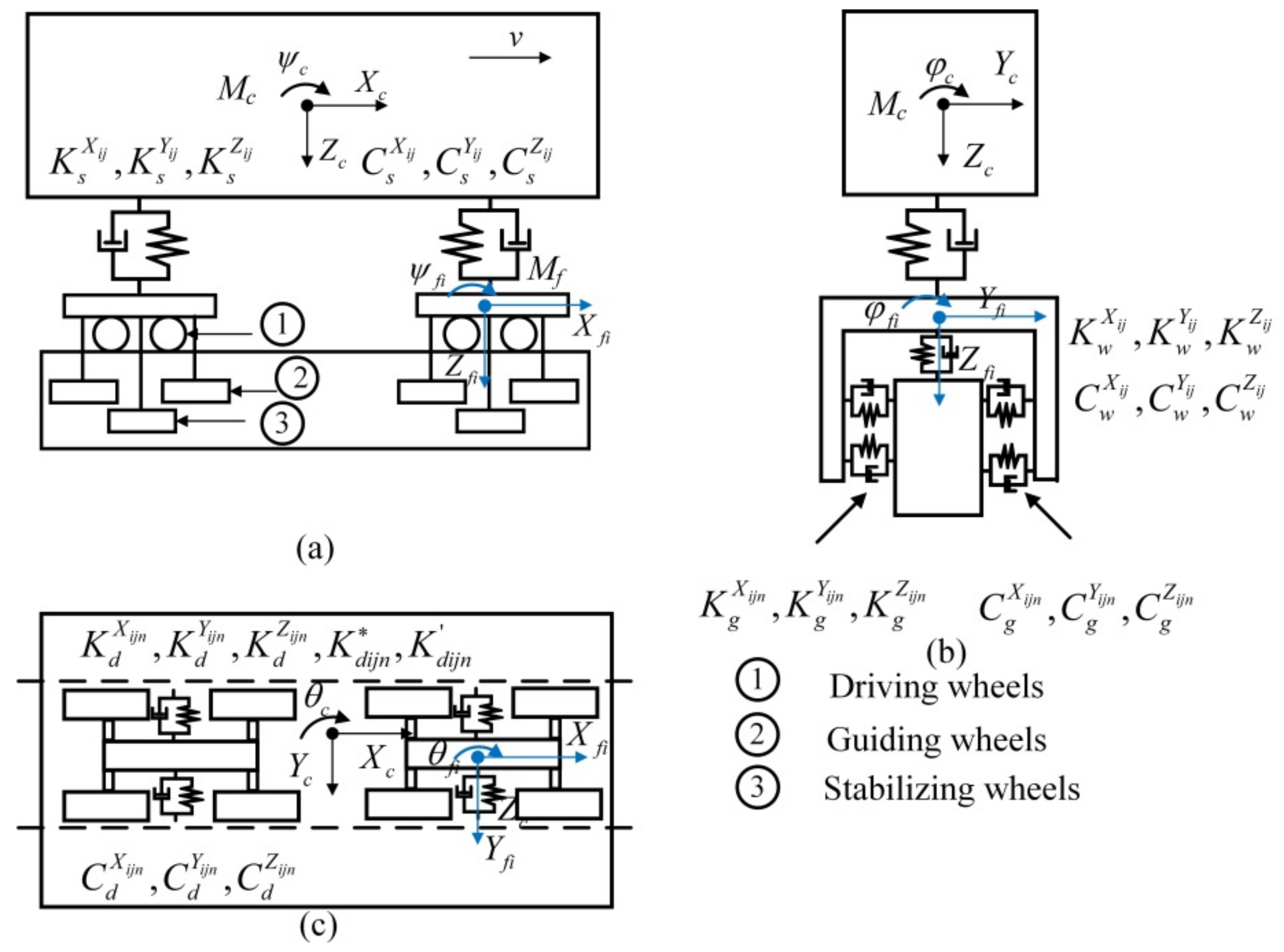
For a single-section straddle-type monorail vehicle, the vehicle body and the front and rear bogies are considered rigid bodies, and the influence of elastic deformation is ignored. The lateral movement Y c , vertical movement Z c , roll movement φ c , pitch movement ψ c and yaw movement θ c of the vehicle body, lateral movement Y f i , vertical movement Z f i , roll movement φ f i , pitch movement ψ f i and yaw movement θ f i of the bogies are considered [10], and the frictional contact behaviors between the tire and the concrete surface are not considered. Figure 3 shows the vehicle dynamic model, and the notations of straddle-type monorail vehicle dynamic mode are shown in Nomenclature.
Based on the Lagrange’s equation (The kinetic energy, potential energy equation and Rayleigh’s dissipation function of the STM system) are included in the Appendix A of the manuscript), the dynamic control differential equation can be obtained as follows:
(1)
The lateral, vertical, roll, pitch, and yaw movement equations of the vehicle body.
M c ( Y ¨ c t + v 2 R c + H f t + H f s + H c s Φ ¨ c t = i = 1 2 j = 1 2 F s Y i j t + M c g Φ c t
M c Z ¨ c t + v 2 R c Φ c t = i = 1 2 j = 1 2 F s Z i j t
J c φ φ ¨ c t + Φ ¨ c t + M R 1 + M R 2 = H c s i = 1 2 j = 1 2 F s Y i j t + b s i = 1 2 j = 1 2 F s Y i j t
J c ψ ψ ¨ c t = H c f i = 1 2 j = 1 2 F s X i j t + l c i = 1 2 j = 1 2 F s Z i j t
J c θ θ ¨ c t + v d d t 1 R c = b s i = 1 2 j = 1 2 F s X i j t + l c i = 1 2 j = 1 2 F s Y i j t
(2)
The lateral, vertical, roll, pitch, and yaw movement equations of the bogies.
M f Y ¨ f i t + v 2 R f i + r 0 + H f t Φ ¨ f i t M f g Φ f i t = i = 1 2 j = 1 2 F s Y i j t + i = 1 2 j = 1 2 n = 1 2 F d Z i j n t + i = 1 2 j = 1 2 n = 1 2 F g Z i j n t + i = 1 2 j = 1 2 F w Z i j t
M f Z ¨ f i t + v 2 R f i Φ ¨ f i t = i = 1 2 j = 1 2 n = 1 2 F d Y i j n t + i = 1 2 j = 1 2 n = 1 2 F g Y i j n t + i = 1 2 j = 1 2 F w Y i j t
J f φ φ ¨ f i t + Φ ¨ f i t = H f t i = 1 2 j = 1 2 n = 1 2 F d Y i j n t + b d i = 1 2 j = 1 2 n = 1 2 F d Z i j n t + H f g i = 1 2 j = 1 2 n = 1 2 F g Z i j n t + H f w i = 1 2 j = 1 2 F w Z i j t + b s i = 1 2 j = 1 2 F s Z i j t + H f s i = 1 2 j = 1 2 F s Y i j t
J f ψ ψ ¨ f i t = l f i = 1 2 j = 1 2 n = 1 2 F d Z i j n t + H f s i = 1 2 j = 1 2 F s X i j t + H f d i = 1 2 j = 1 2 n = 1 2 F d X i j n t + H f g i = 1 2 j = 1 2 n = 1 2 F g X i j n t
J f θ θ ¨ f i t + v d d t 1 R f i = l g i = 1 2 j = 1 2 n = 1 2 F g Y i j n t + b s i = 1 2 j = 1 2 F s X i j t + b g i = 1 2 j = 1 2 n = 1 2 F g X i j n t + l f i = 1 2 j = 1 2 n = 1 2 F d Y i j n t + b g i = 1 2 j = 1 2 F w X i j t 4 k η b g 2 θ ˙ f t v + ψ f i t r 0
where F s X i j t , F s Y i j t , F s Z i j t indicates the secondary suspension force, as shown in Equation (3a–c); F d Z i j n t , F g Z i j n t , F w Z i j n t indicates the radial force of driving wheels, guiding wheels and stabilizing wheels; F d Y i j n t , F g Y i j n t , F w Y i j t indicates the side force of driving wheels, guiding wheels and stabilizing wheels; F d X i j n t , F g X i j n t , F w X i j t indicates the longitudinal slip force of driving wheels, guiding wheels and stabilizing wheels, as shown in Equation (5a–k). M R 1 , M R 2 indicates the shaking moment generated by the cornering force of front and rear bogie driving wheels.
(3)
Secondary suspension force.
F s X i j t = K s X i j H c s ψ c t + H f s ψ f i t ± b s θ c t b s θ f i t C s X i j H c s ψ ˙ c t + H f s ψ ˙ f i t ± b s θ ˙ c t b s θ ˙ f i t
F s Y i j t = K s Y i j Y f i t Y c t + H f s φ f i t + H c s φ c t l c θ c t C s Y i j Y ˙ f i t Y ˙ c t + H f s φ ˙ f i t + H c s φ ˙ c t l c θ ˙ c t
F s Z i j = K s Z i j Z f i t Z c t ± b s φ f i t b s φ c t l c ψ c t C s Z i j Z ˙ f i t Z ˙ c t ± b s φ ˙ f i t b s φ ˙ c t l c ψ ˙ c t
In summary, based on the numbered seating rule, the vehicle motion equation can be obtained from (1a)–(2e).
M v q ¨ v t + C v q ˙ v t + K v q v t = F v t
where M v , C v , K v are the mass, damping, and stiffness matrices of the vehicle system; F v t is the load column vector acting on the vehicle body, front and rear bogies; q v t , q ˙ v t , q ¨ v t are the displacement, velocity, and acceleration column vector of vehicle system.

2.2. Tire Model

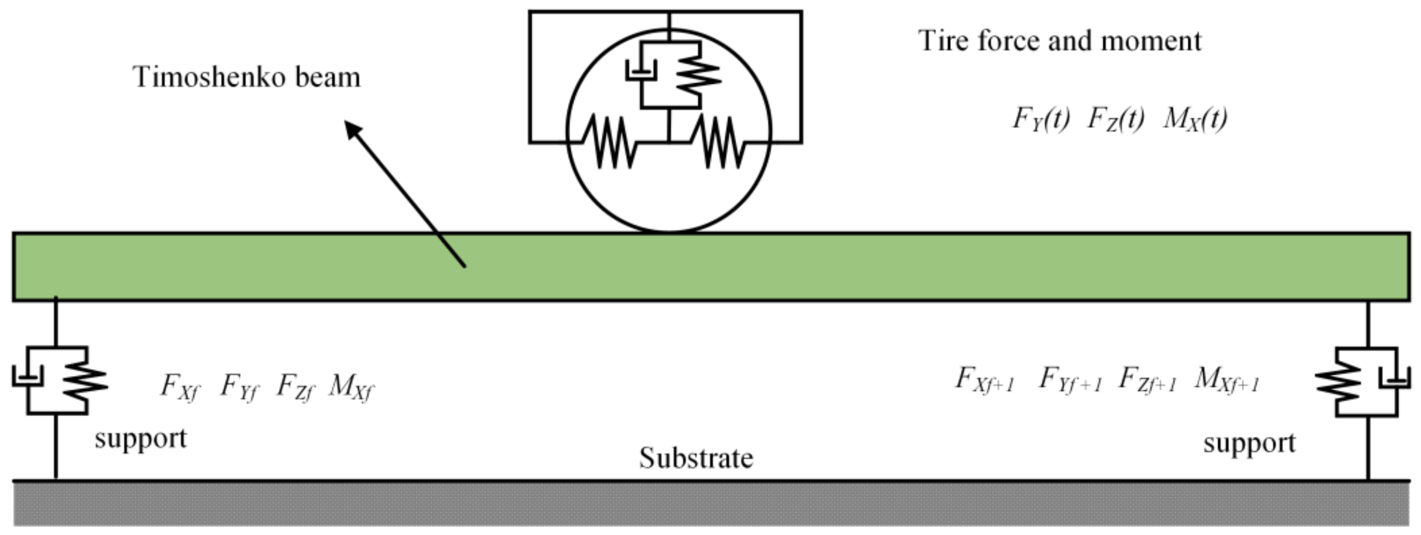
The tire directly acting between the vehicle and the track beam, typically has nonlinear characteristics, so not only the radial stiffness and damping characteristics, but also the side slip and longitudinal sliding characteristics are involved in its dynamic model. For simplification, it is generally assumed that the tire has linear characteristics in the case of small deformations. Therefore, the force and moment of the tire are linearized; this paper makes the following assumptions and the tire model structure diagram is illustrated in Figure 4.
(1)
The tire movement is a slight vibration, the tire deformation is very small, and the stiffness of all tires is linear in all directions;
(2)
Ignore the effects of vertical load changes and tire pressure changes on the stiffness of driving tires;
(3)
Consider the radial stiffness and damping, cornering effect and longitudinal slip of the running wheel tire;
(4)
Consider the radial stiffness and damping and cornering effects of the guide wheel and stabilizer wheel tire;
(5)
Ignoring the camber force and the aligning moment generated by the camber angle.
In summary, the dynamic characteristics of the driving wheels, guiding wheels and stabilizing wheels can be expressed as shown in [11].
(1)
Tire radial force.
The radial model of the rubber wheel can generally be simplified as a point-contact linear damping model, one end of which is connected to the frame and the other end is connected to the track; its radial stiffness depends on the rubber wheel structure and the inflation pressure of the inner tube, and the radial force of each tire is.
F d Z i j n t = K d Z i j n Z f i t l f ψ f i t b φ f i t + C d Z i j n Z ˙ f i t l f ψ ˙ f i t b φ ˙ f i t + K d Z i j n 1 m b g φ f i t Z b t μ z t + C d Z i j n 1 m b g φ ˙ f i t Z ˙ b t μ ˙ z t
F g Z i j n t = K g Z i j n Y f i t Y b t μ y t + K g Z i j n 1 i l g ψ f i t + H f g φ f i t + C g Z i j n Y ˙ f i t Y ˙ b t μ ˙ y t + C g Z i j n 1 i l g ψ ˙ f i t + H f g φ ˙ f i t
F w Z i j t = K w Z i j Y f i t Y b t μ y t H f w φ f i t + C w Z i j Y ˙ f i t Y ˙ b t μ ˙ y t H f w φ ˙ f i t
where K d Z i j n t , K g Z i j n t , K w Z i j t represent the radial stiffness of the driving wheels, guiding wheels and stabilizing wheels; C d Z i j n t , C g Z i j n t , C w Z i j n t represent the radial damping of the driving wheels, guiding wheels and stabilizing wheels; Z b t and μ z t represent the vertical displacement and vertical irregularities of the track beam, respectively; Y b t and μ y t μ y t represent the lateral displacement and vertical irregularities of the track beam, respectively.
(2)
Side force and aligning moment.
The rubber wheel has complex mechanical characteristics, and the radial characteristics and cornering characteristics of the load-bearing wheel and the guide wheel must be considered when establishing the calculation model for analyzing the dynamics.
When a lateral force F acts between the tire and the road surface, the tire will deform elastically in a lateral direction. Therefore, the forward direction of the tire and the direction of the center plane of the tire will form an angle α, which is called the side slip angle, and the lateral force F is called the tire cornering force. For straddle-type monorail traffic, the tire side slip angle is less than 4°. At this time, the cornering force is linearly related to the sideslip angle,
F α = K α α
where F α represent the Side force; K α represent the cornering stiffness, α represent the cornering angle.
As the resultant force of the laterally distributed force between the tire and the road surface, the cornering force does not pass the projection of the wheel center on the road surface, but drags it back a distance, thereby generating a moment on the axis passing through the wheel center perpendicular to the road surface, which is called back-alignment moment, which always tends to reduce the slip angle, and is related to the slip angle as,
M α = K f α
where M α represent the aligning moment; K f represent the aligning stiffness. Suppose the running speed is v, it can be inferred that the slip angle of each tire on the bogie is as follows,
α d = Y ˙ f i t ± θ ˙ f i t l f φ ˙ f i t h r v
α g = Z ˙ f i t ± Ψ ˙ f i t Ψ ˙ f i t b 1 v Ψ f i t
α w = Z ˙ f i t Ψ ˙ f i t b 1 v θ f i t
where α d , α g , α w represent the cornering angle of the driving wheels, guiding wheels and stabilizing wheels. Therefore, the cornering force and the aligning moment can be expressed as:
F d Y i j n t = K d α i j n Y ˙ f i t ± θ ˙ f i t l f φ ˙ f i t h r v θ f i t
M d i j n * t = K d i j n * Y ˙ f i t ± θ ˙ f i t l f φ ˙ f i t h r v θ f i t
F g Y i j n t = K g α i j n Z ˙ f i t ± ψ ˙ f i t l g ψ ˙ f i t b g v ψ f i t
M g i j n * = K g i j n * Z ˙ f i t ± ψ ˙ f t l g ψ ˙ f i t b g v ψ f i t
M w i j * t = K w i j * Z ˙ f i t ψ ˙ f i t b g v θ f i t
where K d α i j , K g α i j , K w α i j represent the cornering stiffness of the driving wheels, guiding wheels and stabilizing wheels; K d i j n * , K g i j n * , K w i j * represent the aligning stiffness of the driving wheels, guiding wheels and stabilizing wheels.
(3)
Longitudinal slip and head shaking moment.
F d X i j n t = K d X i j n b θ f i t v ± φ f i t r 0
M d i j n t = 2 k η b g 2 θ ˙ f i t v + ψ f i t r 0
where K d X i j n represents the longitudinal sliding stiffness of the driving wheels; k η represents the tangential stiffness of the driving wheels. For the same bogie, take the positive sign is taken for the left side tire and the negative sign is taken for the right side.

2.3. Track Beam Model

To order to consider the influence of the shear and torsional deformation of the track beam on the vibration characteristics of the straddle monorail system, a flexible track beam model is established based on the Timoshenko beam theory [12,13,14] and the following assumptions are made: Ignoring the flexibility of the bridge piers and connecting the track beam to the ground through elastic support.
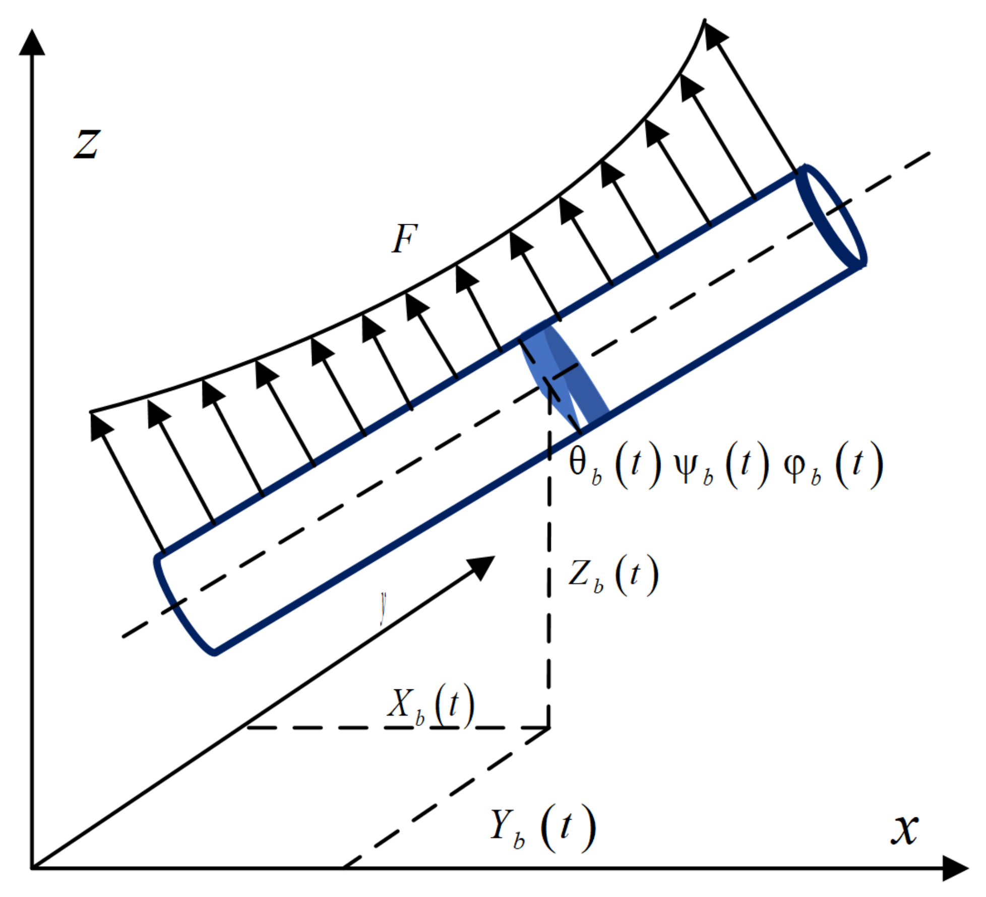
Based on the Timoshenko beam theory [14], the Timoshenko beam element and the dynamic model of the flexible track beam are shown in Figure 5 and Figure 6, considering the longitudinal X b t , lateral Y b t , vertical Z b t , Y-direction shear θ b t , Z-direction shear ψ b t and φ b t torsion around the x axis of the track beam, a total of six directions of vibration.
The potential energy and kinetic energy of the Timoshenko beam element can be expressed as follows:
E b A b 2 X B t x 2 ρ b A b X B 2 t t 2 = i = 1 2 j = 1 2 n = 1 2 F d X i j n t δ x x w t + f Q F X f t
K b y A b G b 2 Y b t x 2 θ b t x ρ b A b 2 Y b t t 2 ρ b z b A b 2 Y b t t 2 = i = 1 2 j = 1 2 n = 1 2 F d Y i j n t δ x x w t i = 1 2 j = 1 2 n = 1 2 F g Y i j n t δ x x w t + i = 1 2 j = 1 2 F w Y i j t δ x x w t + f Q δ x x f F Y f t
K b z A b G b 2 Z b t x 2 ψ b t x ρ b A b 2 Z b t t 2 ρ b y b A b 2 φ b t t 2 = i = 1 2 j = 1 2 n = 1 2 F d Z i j n t δ x x w t + i = 1 2 j = 1 2 n = 1 2 F g Z i j n t δ x x w t + i = 1 2 j = 1 2 F w Z i j t δ x x w t + f Q δ x x f F Z f t
E b J b y 2 ψ b t x 2 K b y A b G b ψ b t x + ψ b ρ b J b y 2 ψ b t t 2 = 0
E b J b z 2 θ b t x 2 + K b y A b G b Y b t x θ b t ρ b J b z 2 θ b t t 2 = 0
E b J b ε 4 φ b t x 4 G b J b x 2 φ b t x 2 ρ b J b ε 4 φ b t x 2 t 2 + ρ b z b A b 2 Y b t t 2 ρ b y b A b 2 Z b t t 2 + ρ b J b p 2 φ b t t 2 = i = 1 2 j = 1 2 n = 1 2 M d i j n t δ x x w t + f Q δ x x f M X f t
where E b , G b respectively represent the modulus of elasticity and shear modulus; ρ b represents the material density of track beam; A b represents the cross-section area; J b y , J b z represent the central principal moments of inertia; J b x represents the st. venant’s torsional constant; J b ε represents the warping constant; K b y , K b z represent the shear correction factors in principal planes; J b p represents the polar moment of inertia; y b , z b represent the coordinates of shear centre relative to the centre of gravity in the principal central frame; δ represents the Dirac delta function; x ω t represents the current longitudinal coordinates of the tire; F X f t , F Y f t , F Z f t , M X f t represent the forces and torques, that act on the track beam form support.

2.4. Vehicle-Track Beam Coupling Model

Based on Equations (4) and (6a–f) and wheel-rail contact relationship Equation (5a–k), a straddle monorail vehicle-flexible track beam coupling dynamic equation is established considering the torsional and shear deformation of the track beam. To perform numerical analysis, Equation (6a–f) are transformed from fourth-order partial differential equations into second-order partial differential equations by the component mode synthesis.
After introducing the generalized coordinates of longitudinal, transverse, vertical, shear and torsion Q X , Q Y , Q Z , Q θ , Q ψ , Q φ respectively, the longitudinal, lateral, vertical, shear and torsion motions of any cross-section of the track beam can be represented by the superposition of the mode shape functions.
X b , Y b , Z b , ψ b , θ b , φ b = ( n = 1 N b ϕ X n x Q X t , n = 1 N b ϕ Y n x Q Y t , n = 1 N b ϕ Z n x Q Z t , n = 1 N b ϕ ψ n x Q ψ t , n = 1 N b ϕ θ n x Q θ t , n = 1 N b ϕ φ n x Q φ t )
where N b represents the number of mode of vibration; ϕ X n x ,   ϕ Y n x ,   ϕ Z n x , and ϕ θ n x ,   ϕ ψ n x , ϕ φ n x are the longitudinal, lateral, vertical, shear and torsional motions of mode shape functions respectively, which can be expressed as:
ϕ X n x = 2 ρ b A b L c o s n π x L , ϕ Y n x = 2 ρ b A b L c o s n π x L ϕ Z n x = 2 ρ b A b L cos n π x L ϕ ψ n x = 2 ρ b J b z L cos n π x L ϕ θ n x = 2 ρ b J b y L cos n π x L ϕ φ n x = 2 ρ b J b ε L cos n π x L
Through formulas (6a–f), (7) and (8), the modal equation of the track beam can be obtained as:
Q ¨ X t + E b ρ b n π L 2 Q X t = ϕ X n x ρ b A b i = 1 2 j = 1 2 n = 1 2 F d X i j n t δ x x w t + f Q F X f t
Q ¨ Y t + n π L 2 K b y J b y G b 1 + z b A b Q Y n t = J b y ϕ Y n 1 + z b i = 1 2 j = 1 2 n = 1 2 F d Y i j n t δ x x w t J b y ϕ Y n 1 + z b i = 1 2 j = 1 2 n = 1 2 F g Y i j n t δ x x w t + f Q δ x x f F Y f t
Q ¨ Z t + n π L 2 K b z J b z G b 1 + y b A b Q z t = J b z ϕ Z n x 1 + y b i = 1 2 j = 1 2 n = 1 2 F d Z i j n t δ x x w t + J b z ϕ Z n x 1 + y b i = 1 2 j = 1 2 n = 1 2 F g Z i j n t δ x x w t + j = 1 2 F w Z i j t δ x x w t + f Q δ x x f F Z f t
Q ¨ ψ t + n π L 2 E b ρ b K b y A b G b ρ b J b y n π L 2 + K b y A b G b ρ b J b y Q ψ t = 0
Q ¨ θ t + n π L 2 E b ρ b + K b z A b G b ρ b J b z n π L 2 K b z A b G b ρ b J b z Q θ t = 0
Q ¨ φ t + n π L 2 E b ρ b + G b J b x ρ b J b ε J b ε 1 + J b p Q φ t = L n π 2 J b ε ϕ φ n x 1 + J b p i = 1 2 j = 1 2 n = 1 2 M X i j n t δ x x w t + L n π 2 J b ε ϕ φ n x 1 + J b p f Q δ x x f M X f t
Based on Equations (4) and (9a–f), the dynamic equation of the vehicle-track beam coupling system was established, as follows:
M q ¨ t + C q ˙ t + K q t = F t
where M , C , K represent the mass, damping, and stiffness matrix of the vehicle and track beam system; q t , q ˙ t , q ¨ t represent the displacement, velocity, and acceleration column vector of vehicle system and track beam system; F t represents the load vector of the vehicle system and track beam system.

2.5. Selection of Calculation Parameters of Vehicle-Bridge Coupling System

(1)
Track beam irregularities.
In this paper, the power spectral density function can be obtained according to the track beam irregularities statistics in Ref. [15], as follows:
S Ω = γ Ω n + β n
where S Ω denotes the power spectral density function of track beam irregularity; Ω denotes the spatial circular frequency; γ ,   β ,   n represent the relevant parameters of the power spectral density function, as shown in Table 1.
Track irregularities can be generated in accordance with PSD function, and the Rice-Pearson algorithm is used to generate the irregularity values by the equation.
w x = m = 0 M 2 S ω m Δ ω m cos ω m x + φ m
where w x is the sequence of track irregularities; Δ ω m is the irregularity step size; M is the total number of harmonics in the sum; S ω m is the PSD function; φ m is the phase uniformly distributed on the interval π , π .
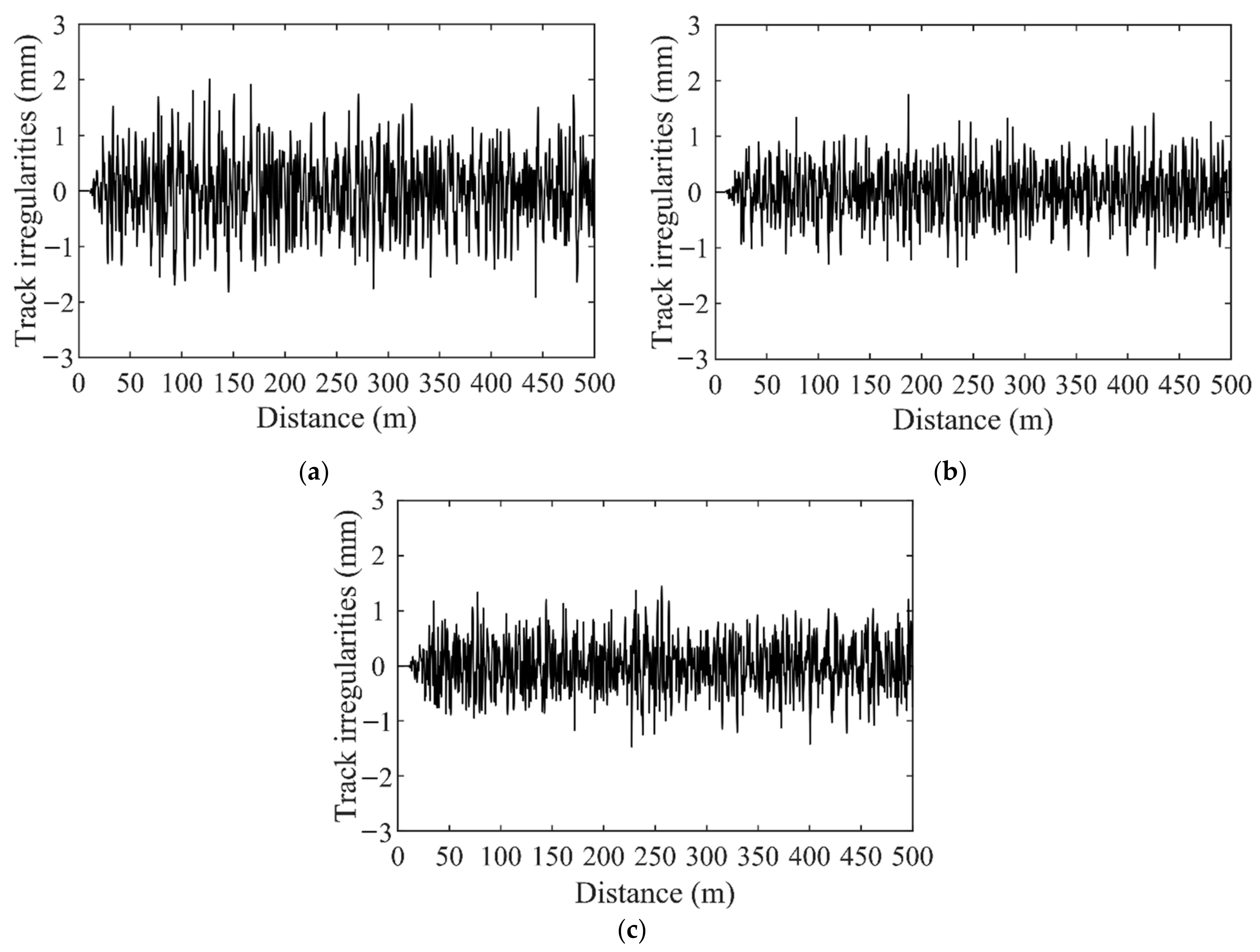
Based on the actual situation of the Chongqing monorail line, this paper uses the Rice-Pearson algorithm to simulate the track irregularity and the results are demonstrated in Figure 7.
(2)
Parameter selection of vehicle-track beam system
In this paper, the elasticity of the piers is ignored and simplified as rigid supports. The stiffness in each direction is taken as 10 10 N m 1 , and the damping is taken as 10 4 N s m 1 . All of the material properties of the track beam system and the parameters of the vehicles system are Ref.d in Ref. [16].

2.6. Model Verification

It is useful to analyze the difference in the calculation results of various straddle-type monorail vehicles-track beam coupling dynamic model to further comprehend the dynamic interaction mechanism of the vehicle-track beam coupling system and determine the scope of application of different coupled dynamic models. At present, in addition to the straddle-type monorail vehicle-track beam coupling dynamic analysis model established in this article, there are two other commonly used models [16]. The main difference among these models exists in the track beam model described by different theories, while the vehicle and tire models are similar. The dynamic response of the straddle-type monorail vehicle-track beam coupling model at different vehicle speeds will be calculated and the results will be compared with the results of Ref. [16] and measured results [17]. We selected Chongqing Line 2 as the model of the actual measurement results, corresponding track beam numbers are Z206-25 and Y210-40. Vehicle speed is 40 km/h and track irregularity spectrum of Ref. [15] is adopted. The comparison of natural vibration characteristics of track beams is shown in Table 2.
From the comparative analysis results in Table 2, it can be seen that the calculated first-order vertical bending and first-order transverse bending frequencies are similar to the natural frequencies of the measured data, and are numerically lower than the measured data. The reasons for this difference are summarized and analyzed as follows: The calculation parameters of the flexible track beam (elastic modulus, moment of inertia and density, etc.) are different from those calculated by the model in this paper. In this paper, the simplified moment of inertia of the flexible track beam system is used in the calculation. In practice, there are steel bars and prestressed tendons in the design section. The accurate simulation should use the converted moment of inertia of the section.
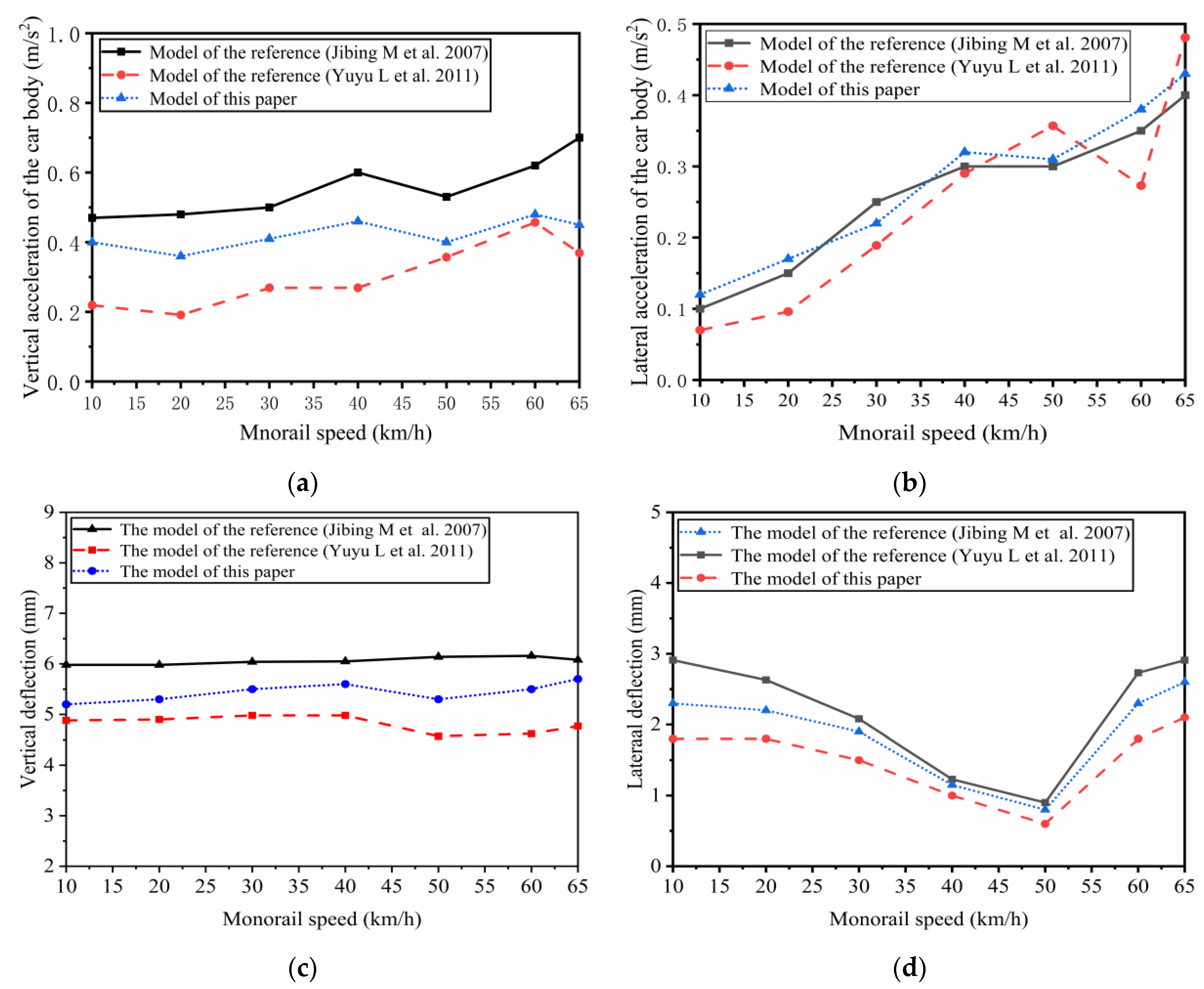
The comparison of the calculation results of the dynamic response index of the vehicle-axle coupling system is shown in Figure 8.
In Figure 8, with the increase of vehicle speed, the model built in this paper is basically the same as the dynamic indexes of Ref. [16]. From a numerical point of view, the model built in this paper is larger than the result of Ref. [16]. Because the shear and torsion variables of the track beam are considered in the model and established, the vibration of the track beam is more complicated. To sum up, when driving on an elevated flexible track beam, the flexible track beam model adopts the Euler beam (Ref. [16]) and Timoshenko beam model respectively, and the dynamic characteristic response of the flexible track beam system is consistent with the speed of the vehicle. The dynamic response data are consistent and consistent in waveform; numerically, the mid-span acceleration of the track beam of the two models is almost the same, and there is not much difference, and the mid-span displacement response only exists when the vehicle speed is high. In general, the dynamic response of the vehicle system and the flexible track beam system calculated by the two models is not very different. For general engineering applications, when the frequency requirements are not high, the rail beam model of Euler beam can be used and sufficient numerical accuracy requirements can be guaranteed; however, when higher frequency characteristics (especially wheel-rail noise issues) need to be paid special attention to, the Timoshenko beam model was used. In addition, compared with the results of the measured model, the models in this paper and Ref. [16] are numerically smaller than the measured results [16], which is caused by the complexity of the actual track irregularity, and the result of the model in this paper is more accurate; it shows that the calculation results of the model and the conclusions of theoretical analysis are more consistent with the high credibility.

3. Influence of Spatial Alignment on Dynamic Characteristics of Straddle-Type Monorail System

For the straddle-type monorail system, the dynamical running safety and vibration stability of driving must be ensured. Therefore, it is particularly important to reduce the dynamic response and transmission between the various subsystems when the vehicle passes over the elevated track beam. Based on this, the dynamic characteristics of the straddle-type monorail system under different spatial alignment (planar and vertical section) characteristics are the main objects to analyze and study. According to Formula (13), the vertical and lateral acceleration of vehicle body (g), the vertical force driving wheels ( F d Z t ), the vertical force of guiding wheels ( F g Z t ) and the sperling index ( W Z ,   W Y ) are selected by the F d Z t dynamic behaviors evaluation system for evaluation [17].
M q ¨ t + F q t , q ˙ t = F t
In the formula, F q t , q ˙ t is the nonlinear suspension vector force; F t is the external excitation, and F t mainly includes the wheel-rail force and centrifugal force caused by the change of the curve radius and the superelevation change.
In this paper, the orbital irregularity is input in the time domain, and the step-by-step integration method is used to solve the dynamic response of the nonlinear system. After obtaining the displacement, velocity and acceleration responses of the vehicle under the disturbance of the line irregularity, the acceleration value at different frequencies is obtained by using the fast Fourier transform (FFT). The stability index method is used to obtain the lateral and vertical stability index of the vehicle.

3.1. Influence of Curve Radius on the Dynamic Behaviors of the Straddle-Type Monorail System

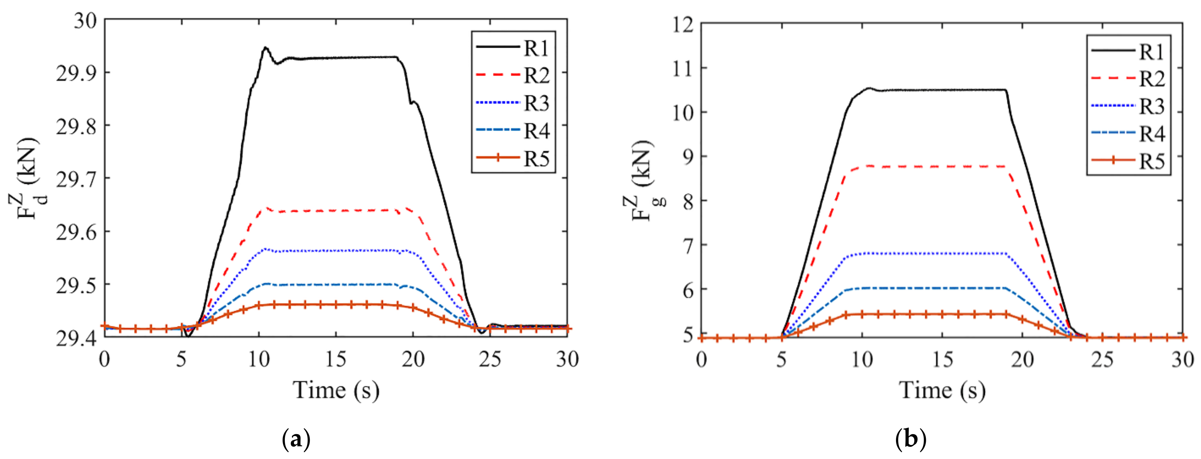
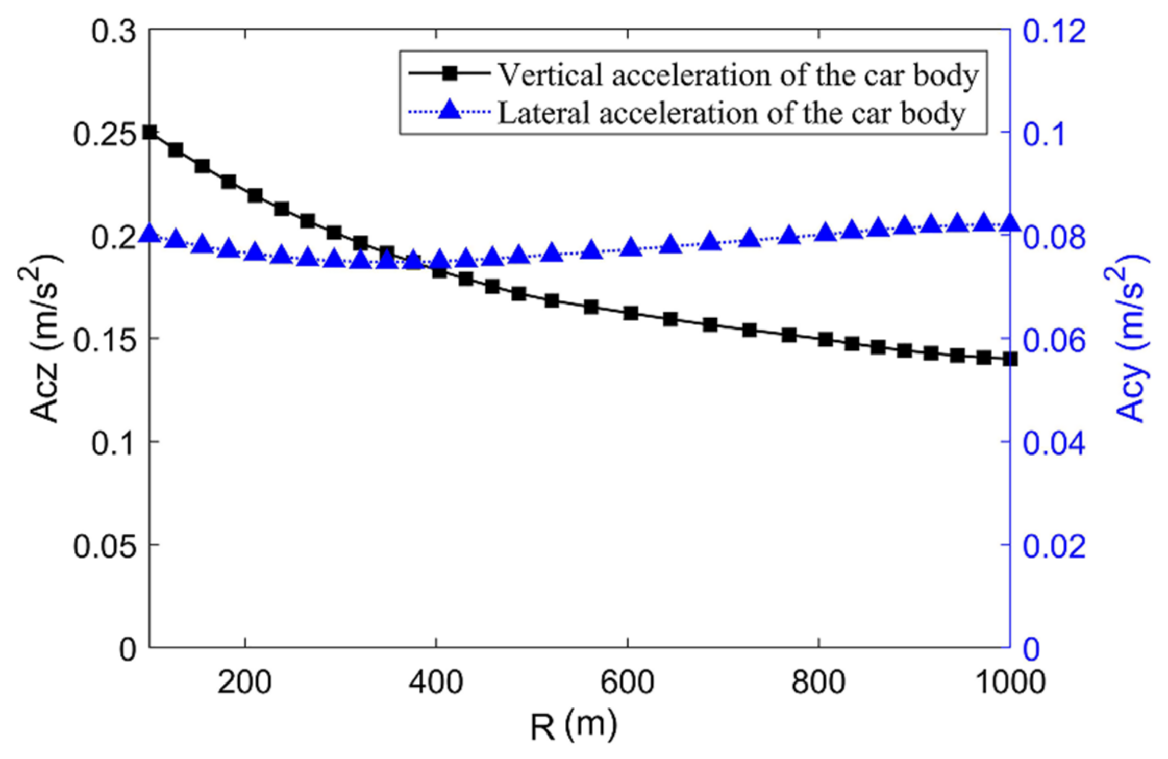
While the straddle-type monorail vehicle runs, the dynamic response of the leading vehicle (MCF) is more obvious than that of the middle vehicle (M1-M4) and the trailing vehicle (MCR), that is, the leading vehicle (MCF) is most sensitive to the complex working conditions of the curve. Therefore, the leading vehicle (MCF) is most suitable for the evaluation of the dynamic characteristics of the straddle-type monorail system in this paper. The vehicle running on elevated track beams with different curve radii at v = 40 km/h is investigated, and after data processing the changing trend of the vehicle system running safety indexes when the curve radius changes within the range of 100~1000 m are obtained, as shown in Figure 9 and Figure 10. (Note, R1 = 100 m, R2 = 300 m, R3 = 500 m, R4 = 800 m, R5 = 1000 m).
In Figure 9, the vertical force of the driving wheels and guiding wheels decreases with the increase of the curve radius. When curve radius (R) exceeds 500 m, the vertical force of the driving wheels and guiding wheels decreases slowly and the curve fluctuation becomes relatively smooth, thus, the stability gradually increases and the ability of vehicle to pass the curve is improved. In Figure 10, during the curve-passing, the vertical acceleration of the vehicle body decreases sharply and then slowly after R = 500 m, meanwhile, the lateral acceleration of vehicle body is rarely affected by the radius of the curve. Compared with the vertical vibration, the lateral vibration of the vehicle body has a greater variation when the curve radius is small, which in turn affects the dynamical running safety and stability of the vehicle. Therefore, increasing the curve radius can effectively improve the lateral stability of the vehicle when passing the curve.

3.2. Influence of the Longitudinal Slope Gradient on the Dynamic Characteristics of the Straddle-Type Monorail System

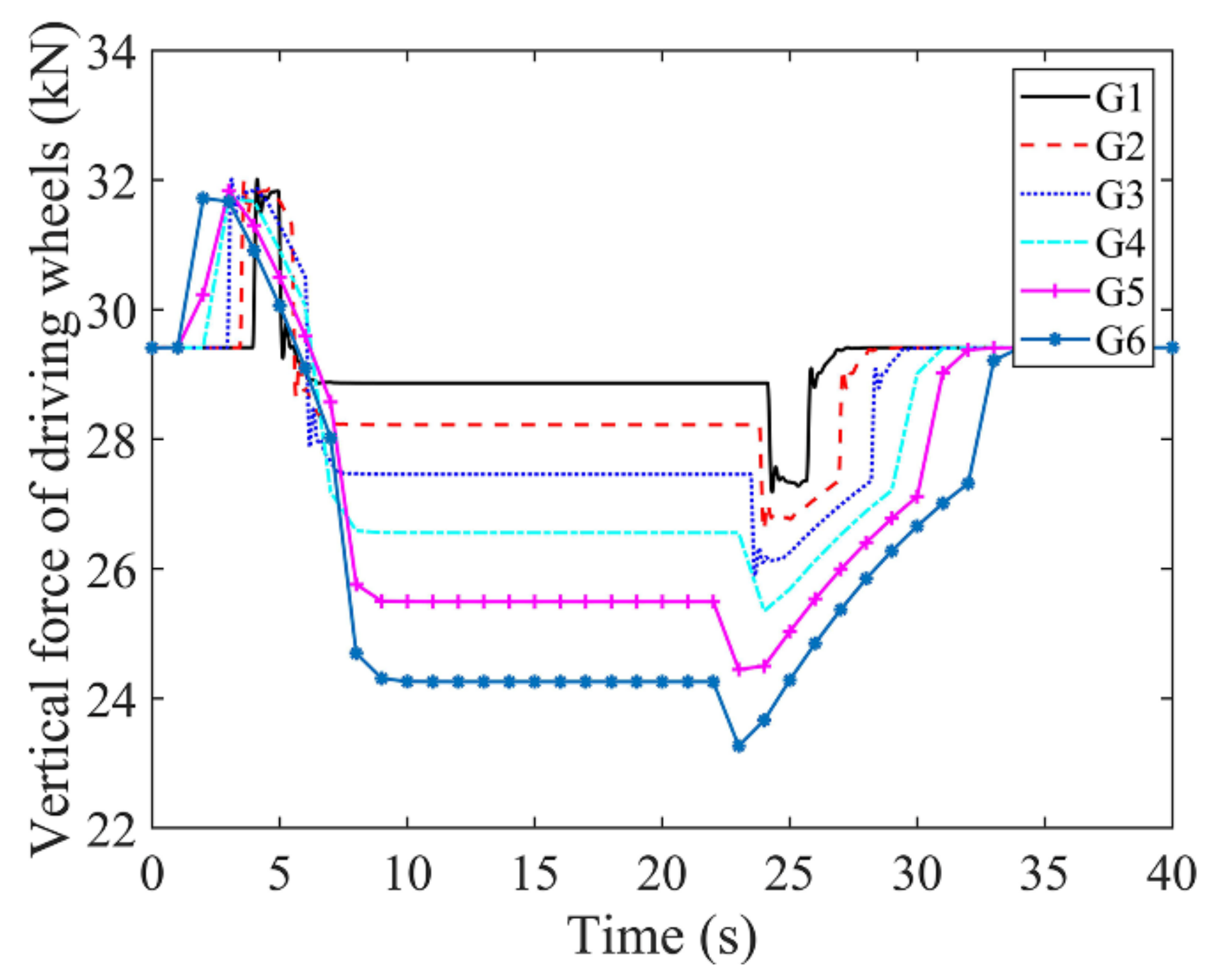
The longitudinal slope gradient is also an important factor affecting dynamic response of the vehicle system. An unreasonable setting of longitudinal slope gradient will increase the rate of change of vertical load of the driving wheels, aggravate the vibration of the vehicle system, then negatively affect the dynamical running safety and the vibration stability of the vehicle system and even cause traffic accidents. Therefore, in this section, the range of variation of preset longitudinal slope gradient G is 0–6% [18], without considering the radius of the curve, and other parameters are the same as the previous section. The changing trend of the straddle-type monorail system dynamical running safety indexes is shown in Figure 11 and Figure 12. (Note, G1 = 1%, G2 = 2%, G3 = 3%, G4 = 4%, G5 = 5%, G6 = 6%)
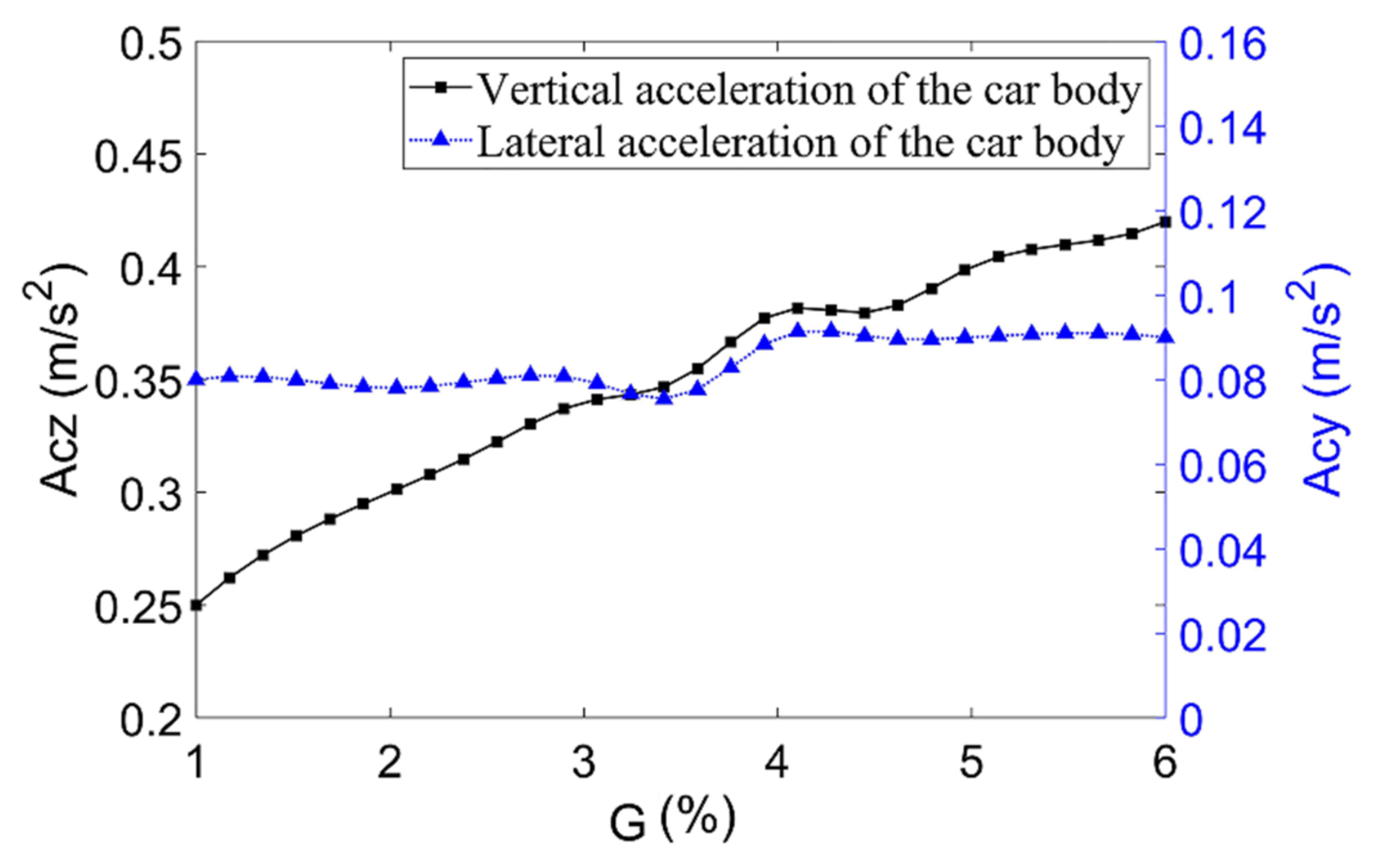
In Figure 11 and Figure 12, the longitudinal slope gradient of the straight line mainly affects the vertical vibration of the vehicle. The vertical force of the driving wheels increases with the increase of the longitudinal slope gradient, and the vibration is more obvious when the vehicle passes through the slope-changing point of change. Every 1% increase in the longitudinal slope gradient brings the increase of vertical force of the running wheel and vertical acceleration of the vehicle body by 10.8% and 8.2%, but the lateral acceleration of the vehicle body is not sensitive to changes, indicating that the longitudinal slope gradient has little effect on the lateral vibration of the vehicle body. To analyze the reasons, as the longitudinal slope gradient increases, centrifugal force mainly generated on the vertical plane when the vehicle passes vertical curve, will increase the rate of change of the vertical force of the driving wheels, resulting in an unfavorable force condition between the driving wheels and rails causing the extremely complicated vertical vibration of the vehicle, and then the poor dynamical running safety of the vehicle operation.

3.3. Dynamic Characteristics of Straddle-Type Monorail System under Compound Conditions of Planar and Vertical Lines

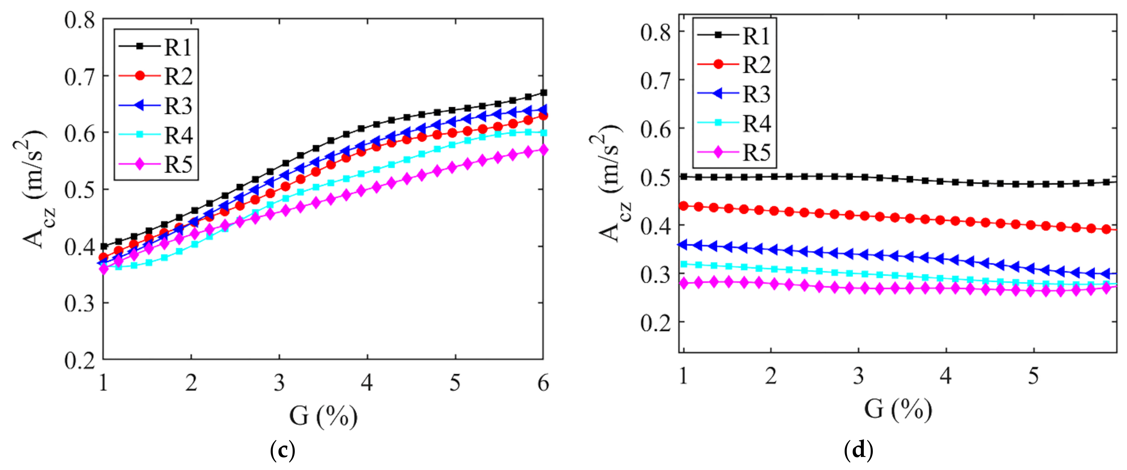
As straddle-type monorail transportation is mainly distributed in mountainous cities with large ground undulations and mostly on elevated curved lines, the vibration of vehicles traveling on elevated track beams is unusually complex and the dynamic performance is poor. Therefore, it is necessary to analyze the dynamic characteristics of straddle-type monorail systems under composite line conditions in planar and vertical sections. The curve radius R and the longitudinal slope gradient G are varied in the range of 100 to 1000 m and 1% to 6%, respectively, without considering the track unevenness, the straight-slowing point coincides with the grade change point and the rest of the parameters are the same as those in the previous section. The dynamic characteristics of the straddle-type monorail system under the composite working conditions of the planar and vertical section line are shown in Figure 13.
In Figure 13, under the condition of the planar and vertical composite line, the indexes of vehicle dynamic characteristics are reduced with the increase of the curve radius and the decrease of the longitudinal slope gradient. When the longitudinal slope gradient G remains unchanged and the curve radius R increases by 100 m, the vertical force of the driving wheels and the guiding wheels decreases by 11.3% and 15.6% and the vertical acceleration increases by 3.5%, while the lateral acceleration is not sensitive to the changes. When the vehicle passes through the plane curve and the vertical curve, the centrifugal force is generated on the vertical plane, increasing the rate of change of the wheel-rail force, causing the unfavorable force condition between the wheel and the rail, and resulting in the deterioration of the dynamical running safety.

3.4. Influence of the Relative Position Change of the Straight-Slowing Point and the Slope-Changing Point on the Dynamic Characteristics of the Straddle-Type Monorail System

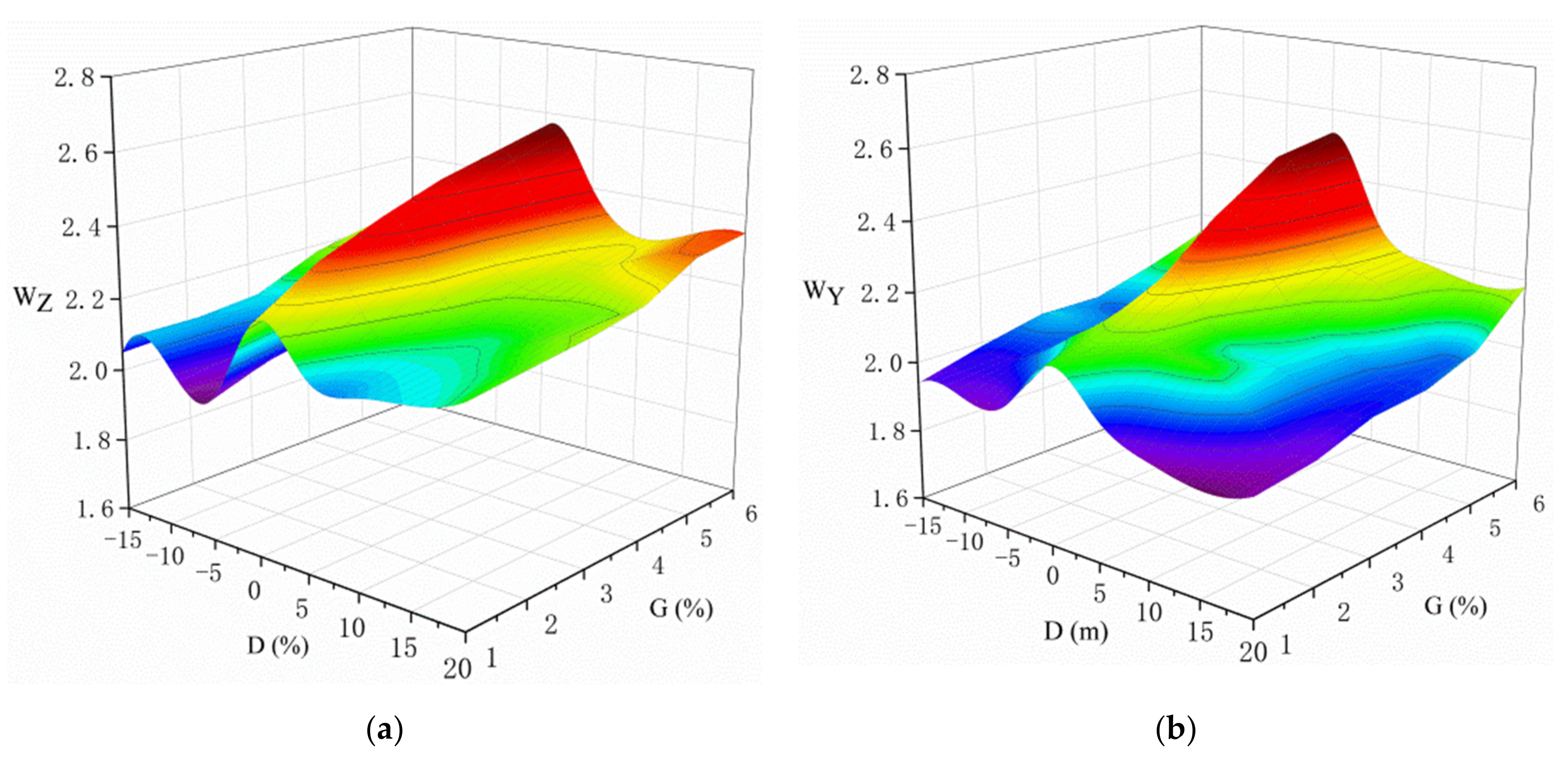
From the previous analysis, it is discovered that when the vehicle is running in the planar and longitudinal composite line, the stress state between the wheel and rail is the worst; meanwhile, the dynamic behavior is poor, and the vehicle vibration is extremely complex. Therefore, it is necessary to study the influence of the change of the relative position between the slope-changing point of the vertical curve and the straight-slowing point of the plane curve on the dynamic characteristics of the straddle-type monorail system. In this section, the distance D of the slope-changing point relative to the straight-slowing point varies in the range of 15−20 m (note: the slope-changing point is considered as a negative value after the straight-slowing point and the opposite is considered as a positive value), the track beam irregularities are considered (as shown in Figure 7), and the rest of the parameters are the same as those in the previous section. Finally, the change of vehicle dynamic characteristics indexes under two working conditions of curve radius R = 100 m (working condition 1) and longitudinal gradient G = 6% (working condition 2) are obtained, respectively, as shown in Figure 14 and Figure 15. (Note, D1 = −15 m, D2 = −10 m, D3 = −5 m, D4 = 0 m, D5 = 5 m, D6 = 10 m, D7 = 15 m, D8 = 20 m).
In Figure 14 and Figure 15, the vehicle stability first increases and then decreases. When the transition curve of the track beam coincides with the vertical curve (slope-changing point), the vehicle vibration stability index (W) exceeds the threshold of 2.5, indicating poor vibration stability. Therefore, in the design of planar and vertical lines, a reasonable setting of the relative position between the straight-slowing point and the slope-changing point is beneficial for the improvement of the dynamical running safety of the vehicle. The relative position of the straight-slowing point and the slope-changing point has a complex impact on the dynamic characteristics of the vehicle, especially when the slope-changing point coincides with the transition curve of the track beam, significant vertical and lateral shock vibrations will be generated when the vehicle passes and exits the curve. For the track beam design, the slope-changing point should not overlap with the transition curve of the track beam. In addition, the slope-changing point should be avoided coinciding with the straight-slowing point.

4. Conclusions

This study proposes a novel dynamic modeling method by using the straddle-type monorail vehicle-track beam coupling system considering the spatial alignment, and the influence of spatial alignment on the vibration stability and running safety of the STM system are investigated. The main conclusions are listed as follows:
(1)
A new coupling dynamic model of STM considering the spatial alignment is established by incorporating the shear and torsion deformation of the track flexible beam system and the non-linear characteristics of the vehicle suspension system.
(2)
The indexes of running safety and vibration stability of the vehicle decrease with the decrease of curve radius or the increase of longitudinal slope gradient. With the increase in the relative position between the slope-changing point and the straight-slowing point, the dynamic driving safety and vibration stability indexes increase first and then decrease. The maximum value is observed when the straight-slowing points coincide with the slope-changing points. In addition, when the slope-changing point coincides with the transition curve of the track beam, the vibration response of the vehicle is more obvious than that when the straight-slowing points do not coincide with the slope-changing points.
(3)
From the viewpoint of dynamical running safety and vibration stability, the slope-changing point should be avoided to coincide with the area of the straight-slowing point. The straight-slowing point and slope-changing point should be located 5–15 m apart to obtain optimized minor dynamic responses of the straddle-type monorail coupling system.
(4)
The refined straddle-type monorail-track coupling dynamic analysis model established in this paper comprehensively considers the influence of nonlinear characteristics such as shear and torsional deformation of the track beam. noise problem), the calculation accuracy of the model in this paper is high, which greatly improves the application range of the calculation model.

Author Contributions

Conceptualization, H.L. and X.X; writing—original draft preparation, H.L.; writing—review and editing, X.X. and X.H.; supervision, X.X.; visualization, Q.C. All authors have read and agreed to the published version of the manuscript.

Funding

This research was funded by the Chongqing Science Fund for Distinguished Young Scholars (cstc2021jcyj-jqX0010), and the Scientific Research Key Fund of Chongqing Municipal Education Commission (No. KJZD-K202000703).

Institutional Review Board Statement

Not applicable.

Informed Consent Statement

Not applicable.

Data Availability Statement

Not applicable.

Conflicts of Interest

The authors declare no conflict of interest.

Nomenclature

A b Cross-section area of track beam
b d , b g Half of the lateral span of the driving wheels, guiding wheels and stabilizing
b s Half of the lateral span of the secondary suspension
C d Z i j n , C g Z i j n , C w Z i j n Vertical damping of bogie tires
C v , C b Damping matrix of vehicle system and track beam system
D Distance of the slope-changing point relative to the straight-slowing point
E b Elasticity modulus of track beam
F d Z i j n , F g Z i j n , F w Z i j Vertical force of bogie tires
F d Y i j n , F g Y i j n , F w Y i j Side force of bogie tires
F X f t , F Y f t   , F Y f t The longitudinal, lateral and vertical forces acting on the track from the support
F v , F b Load column vector of the vehicle body, front and rear bogies
G Longitudinal slope gradient
G b Shear modulus of track beam
H c s Height of the vehicle body centre of gravity to the upper surface of the secondary suspension system
H f s Height of the frame centre of gravity to the lower surface of the secondary suspension system
H f t Height of the frame centre of gravity to the surface of the track beam
H f w Height of the frame centre of gravity to the centre of stabilizing wheels
H f g Height of the frame centre of gravity to the centre of guiding wheels
J b y , J b z Moment of inertia of track beam section relative to Z-axis and Y-axis
J b x St. venant’s torsional constant of track beam
J b ε St. venant’s torsional constant of track beam
J b p Polar moment of inertia of track beam
J c φ , J c ψ , J c θ Mass moment of inertia of vehicle body
J f φ , J f ψ , J f θ Mass moment of inertia of bogies
K s X i j , K s Y i j , K s Z i j Spring constant of air spring
K d Z i j n , K g Z i j n , K w Z i j Vertical spring constant of bogie tires
K b y , K b z Shear correction factors in principal planes of track beam system
K v , K b Stiffness matrix of vehicle and track beam system
l c Half of the longitudinal distance between front and rear bogies
l f Half of bogie wheelbase
l g Half of guiding wheels wheelbase
M c , M f Mass of vehicle body and bogies
M d i j n * , M g i j n * , M w i j n * Aligning moment of bogie tires
M v , M b Mass matrix of vehicle system and track beam system
M X f t Moment (relative longitudinal track axis) that act on the track from the support
M R 1 ,   M R 2 The shaking moment generated by cornering force of front and rear bogie driving wheels
q v t Displacement of vehicle system
q ˙ v t Velocity of vehicle system
q ¨ v t Acceleration of vehicle system
q b t Displacement of track beam system
q ˙ b t Velocity of track beam system
q ¨ b t Acceleration of track beam system
R Curve radius
y b , z b Coordinates of shear centre relative to centre of gravity in principal central
Y c t , Z c t Lateral and vertical moment of the vehicle body
φ c t , ψ c t , θ c t The roll, pitch and yaw moment of the vehicle body
Y f i t , Z f i t The lateral and vertical moment of the bogies
φ f i t , ψ f i t , θ f i t The roll, pitch and yaw moment of the bogies
X b t , Y b t , Z b t The longitudinal, lateral and vertical moment of the track beam
φ b t , ψ b t Shear and torsion moment of the track beam
δ Dirac delta function
ρ b Material density of track beam
T v The kinetic energy of the STM
U v q The potential energy of the STM
U v e The Rayleigh’s dissipation function
ξ b Damping ratio of track beam system
ω b Lowest frequency that corresponds to pinned-pinned vibration mode
μ y t , μ z t The lateral and vertical irregularities
δ f , δ v Superelevation angle of the outer rail at the track where the centre of the frame and vehicle is located
Subscripts
b Track beam system
c Vehicle system
f Degree of freedom identifier of the vehicle system
S The secondary suspension force
x , y , z x, y, z direction
d , g , w The driving wheels, guiding wheels and stabilizing wheels

Appendix A

T v T v = 1 2 M c Y ˙ c 2 + Z ˙ c 2 + J c φ φ ˙ c 2 + J c Ψ Ψ ˙ c 2 + J c θ θ ˙ c 2 + 1 2 j = 1 2 M f i Y ˙ f i 2 + Z ˙ f i 2 + J f φ j φ ˙ f i 2 + J f Ψ i Ψ ˙ f i 2 + J f θ i θ ˙ f i 2
U v q U v q = 1 2 j = 1 2 K s X b s 2 φ c φ f j 2 + H c s θ c + H f s θ f i 2 + K s Y Y c Y f j H c s φ c H f s φ f j + η j s Ψ c + K s Y Z c Z f j + η j s θ c 2 + b s 2 φ c + φ f i 2
U v e U v e = 1 2 j = 1 2 C s X b s 2 Ψ c Ψ f j 2 + H c s θ c + H f s θ f i 2 + C s Y Y c Y f j H c s φ c H f s φ f j + η j s Ψ c + C s Y Z c Z f j + η j s θ c 2 + b s 2 φ c + φ f i 2

References

  1. Timan, P.E. Why monorail systems provide a great solution for metropolitan areas. Urban Rail Transit 2015, 1, 13–25. [Google Scholar] [CrossRef]
  2. Goda, K.; Nishigaito, T.; Hiraishi, M.; Iwasaki, K. A curving simulation for a monorail car. In Proceedings of the 2000 ASME/IEEE Joint Railroad Conference, Newark, NY, USA, 6 April 2000; pp. 171–177. [Google Scholar]
  3. Zhang, J.; Huang, Y.; Fu, L.; Tao, G. Research on the pre-pressure of the steering tire and stabilizing tire of a straddle-type monorail car. Railw. Locomot. Car 2011, 31, 48–52. [Google Scholar]
  4. Du, Z.; Wang, X. Research on stability simulation for straddle-type monorail vehicle. Railw. Locomot. Car 2009, 29, 56–59. [Google Scholar]
  5. Gou, H.; Zhou, W.; Yang, C.; Bao, Y.; Pu, Q. Dynamic Response of a Long-Span Concrete-Filled Steel Tube Tied Arch Bridge and the Riding Comfort of Monorail Trains. Appl. Sci. 2018, 8, 650. [Google Scholar] [CrossRef]
  6. Naeimi, M.; Tatari, M.; Esmaeilzadeh, A.; Mehrali, M. Dynamic interaction of the monorail-bridge system using a combined finite element multibody-based model. Proc. Inst. Mech. Eng. Part K J. Multi-Body Dyn. 2014, 229, 132–151. [Google Scholar] [CrossRef]
  7. Naeimi, M.; Tatari, M.; Esmaeilzadeh, A. Dynamic of the Monorail Train Subjected to the Braking on a Straight Guideway Bridge. Arch. Mech. Eng. 2018, 3, 363–375. [Google Scholar] [CrossRef]
  8. Wang, H.; Zhu, E.; Chen, Z. Dynamic Response Analysis of the Straddle-Type Monorail Bridge–Vehicle Coupling System. Urban Rail Transit 2017, 3, 172–181. [Google Scholar] [CrossRef]
  9. Liu, Y.; Ge, Y.; Yang, Y. Vibration characteristic of coupled system for straddle-type monorail beam and train. J. Traffic Transp. Eng. 2010, 10, 46–53. [Google Scholar]
  10. Zhang, J. Research on Dynamic of Straddle Monorail Car. Master’s Thesis, Southwest Jiaotong University, Chengdu, China, 2009. [Google Scholar]
  11. Ma, J. Research on Structural Static and Dynamic Behaviors of Straddle-Type Monorail Transportation System. Ph.D Thesis, Southwest Jiaotong University, Chengdu, China, 2008. [Google Scholar]
  12. Kahrobaiyan, M.H.; Asghari, M.; Ahmadian, M.T. A Timoshenko beam element based on the modified couple stress theory. Int. J. Mech. Sci. 2014, 79, 75–83. [Google Scholar] [CrossRef]
  13. Dehrouyeh-Semnani, A.M.; Bahrami, A. On size-dependent Timoshenko beam element based on modified couple stress theory. Int. J. Eng. Sci. 2016, 107, 134–148. [Google Scholar] [CrossRef]
  14. Wang, B.; Zhao, J.; Zhou, S. A micro scale Timoshenko beam model based on strain gradient elasticity theory. Eur. J. Mech. A/Solids 2010, 29, 591–599. [Google Scholar] [CrossRef]
  15. Ni, Y.; Ye, S.; Song, S. An experimental study on constructing mr secondary suspension for high-speed trains to improve lateral ride comfort. Smart Struct. Syst. 2016, 18, 53–74. [Google Scholar] [CrossRef]
  16. Liu, Y. Research on Dynamic Interaction of Straddle Type Monorail Vehicle and Track Beam. Ph.D Thesis, Southwest Jiaotong University, Chengdu, China, 2011. [Google Scholar]
  17. Ma, J.; Pu, Q.; Xia, Z. Experimental research on the Chongqing straddle-type monorail transportation system under dynamic loading. J. Railw. Eng. Soc. 2007, 24, 69–75. [Google Scholar]
  18. GB 50458:2008; Code for Design of Straddle Monorail Transit. China Building Industry Press: Beijing, China, 2009.
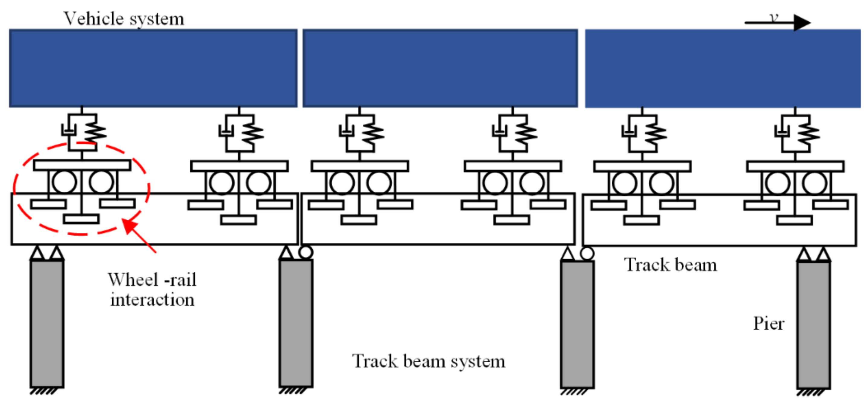
Figure 1. The dynamic model of the straddle-type monorail vehicle-track beam coupling system.
Machines 10 00724 g001
Figure 2. Schematic diagram of straddle-type monorail marshalling.
Machines 10 00724 g002
Figure 3. Dynamic model of vehicle subsystem: (a) right view; (b) front view; (c) top view. where i = 1, 2 indicates the positions of the front and rear bogies; j = 1, 2 indicates the positions of the left and right bogies; n = 1, 2 indicates the front and rear tires of the same bogie.
Machines 10 00724 g003
Figure 4. Relationship between tire model and vehicle model.
Machines 10 00724 g004
Figure 5. A Timoshenko beam model: kinematic parameters, loadings and coordinate system.
Machines 10 00724 g005
Figure 6. Dynamic model of flexible track beam subsystem.
Machines 10 00724 g006
Figure 7. Track beam irregularities: (a) Driving wheels; (b) Guiding wheels; (c) Stabilizing wheels.
Machines 10 00724 g007
Figure 8. The validation of the dynamic model with Yuyu L et al., 2011 and Jibing M. 2007 [16,17]: (a) The vertical acceleration of the vehicle body; (b) The lateral acceleration of the vehicle body; (c) The vertical deflection at the middle span; (d) The lateral deflection at middle span.
Machines 10 00724 g008
Figure 9. Record of vertical force of driving wheels: (a) Record of vertical force of driving wheels; (b) Record of vertical force of guiding wheels.
Machines 10 00724 g009
Figure 10. Maximum of vehicle body acceleration.
Machines 10 00724 g010
Figure 11. Record of vertical force of guiding wheels.
Machines 10 00724 g011
Figure 12. Maximum of vehicle body acceleration.
Machines 10 00724 g012
Figure 13. The dynamic characteristics evaluation indexes: (a) The vertical force peak curve of driving wheels; (b) The vertical force peak curve of guiding wheels; (c) The vertical acceleration of the vehicle body; (d) The lateral acceleration of the vehicle body.
Machines 10 00724 g013aMachines 10 00724 g013b
Figure 14. The vibration stability under R = 100 m working condition: (a) The vertical sperling index of the vehicle body; (b) The lateral sperling index of the vehicle body.
Machines 10 00724 g014
Figure 15. The vibration stability under G = 6% working condition: (a) The vertical sperling index of the vehicle body; (b) The lateral sperling index of the vehicle body.
Machines 10 00724 g015
Table 1. Track beam irregularities coefficient.
The Wheels γ β n
driving wheels0.00050.353.00
guiding wheels0.00060.502.80
stabilizing wheels0.00060.502.60
Table 2. The comparison of natural vibration characteristics of track beam.
Serial NumberCalculate Frequency(Hz)Measured Frequency(Hz)Mode of VibrationError Analysis
Z206-253.6703.882first-order lateral bend−5.46%
7.0127.178first-order vertical bend−2.31%
Y210-408.5459.180first-order lateral bend−6.9%
4.6064.639first-order vertical bend−0.71%
Publisher’s Note: MDPI stays neutral with regard to jurisdictional claims in published maps and institutional affiliations.