
Investigation of the Temperature Effects on Copper Losses in Hairpin Windings


Abstract
:1. Introduction
2. Background
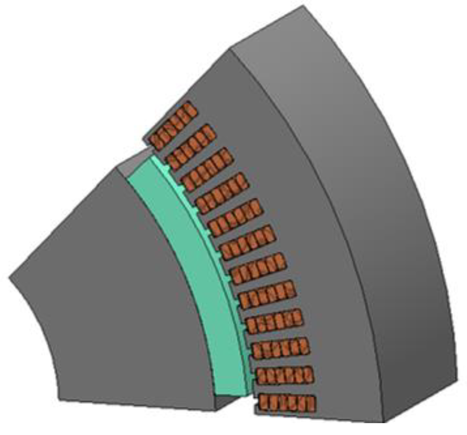
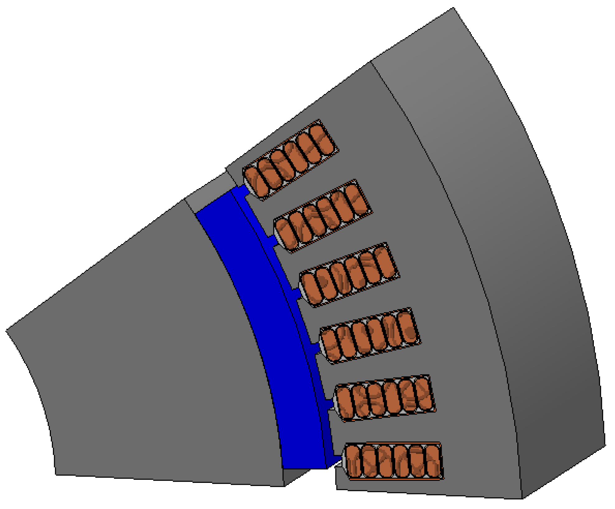
3. Practical Design
First Rotor Topology
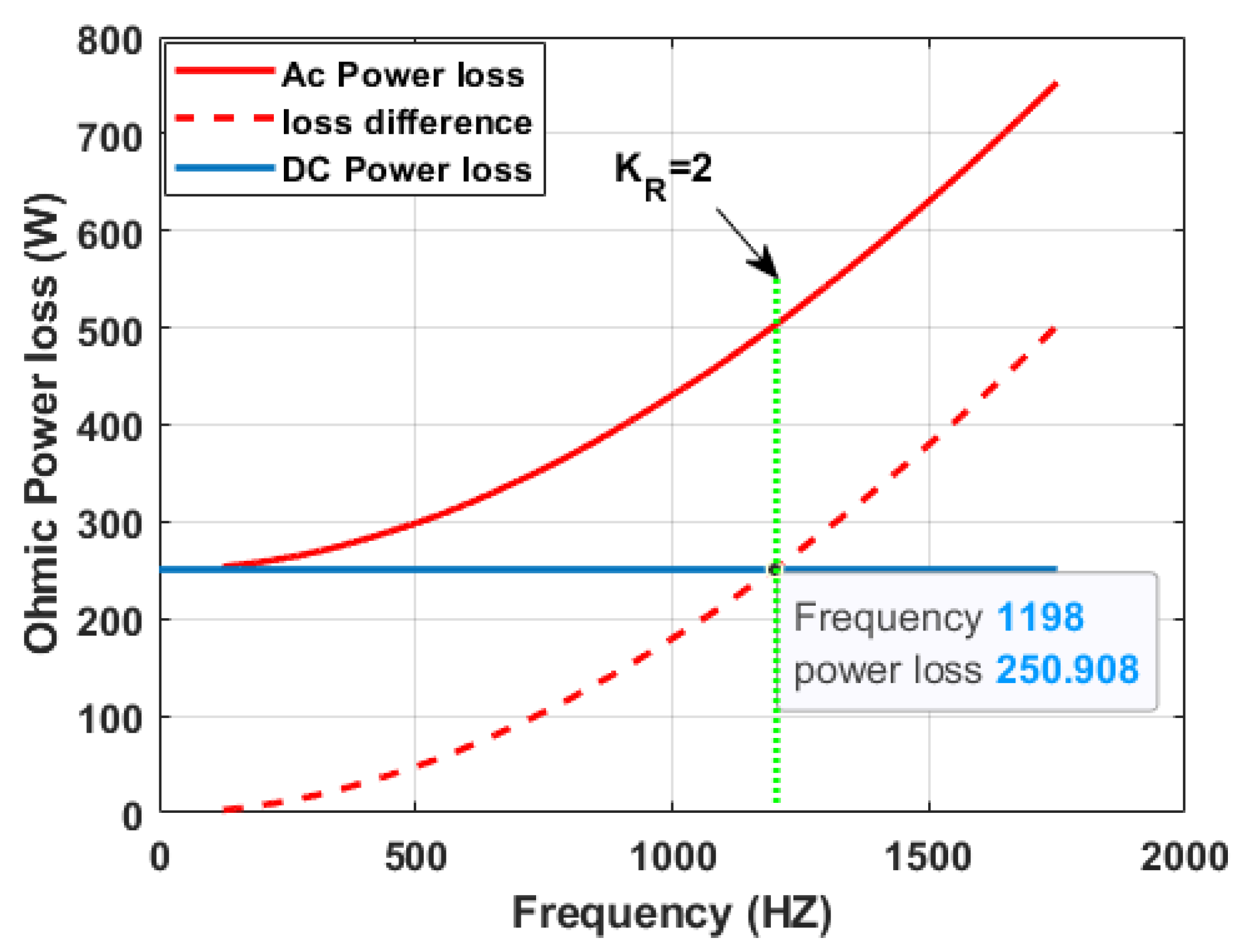
4. Analysis of Ohmic Losses versus Temperature
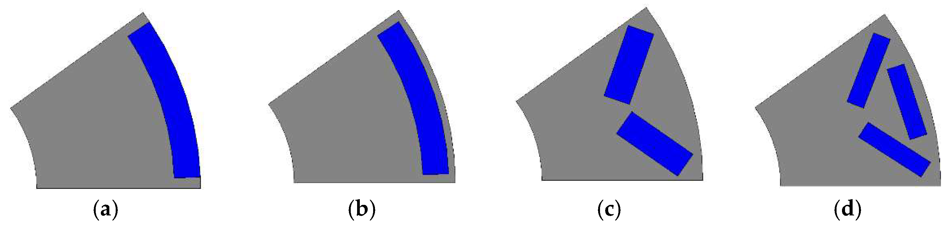
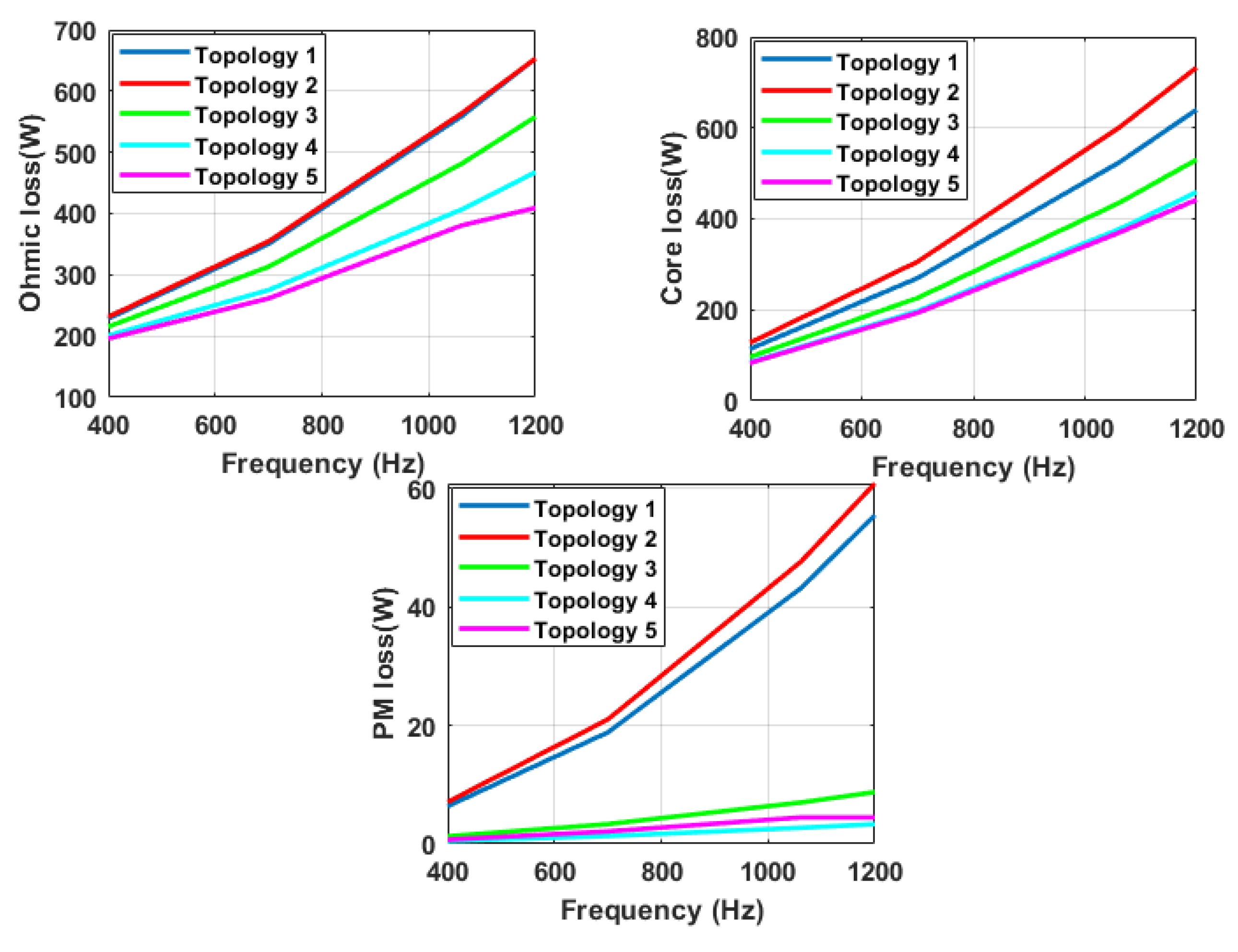
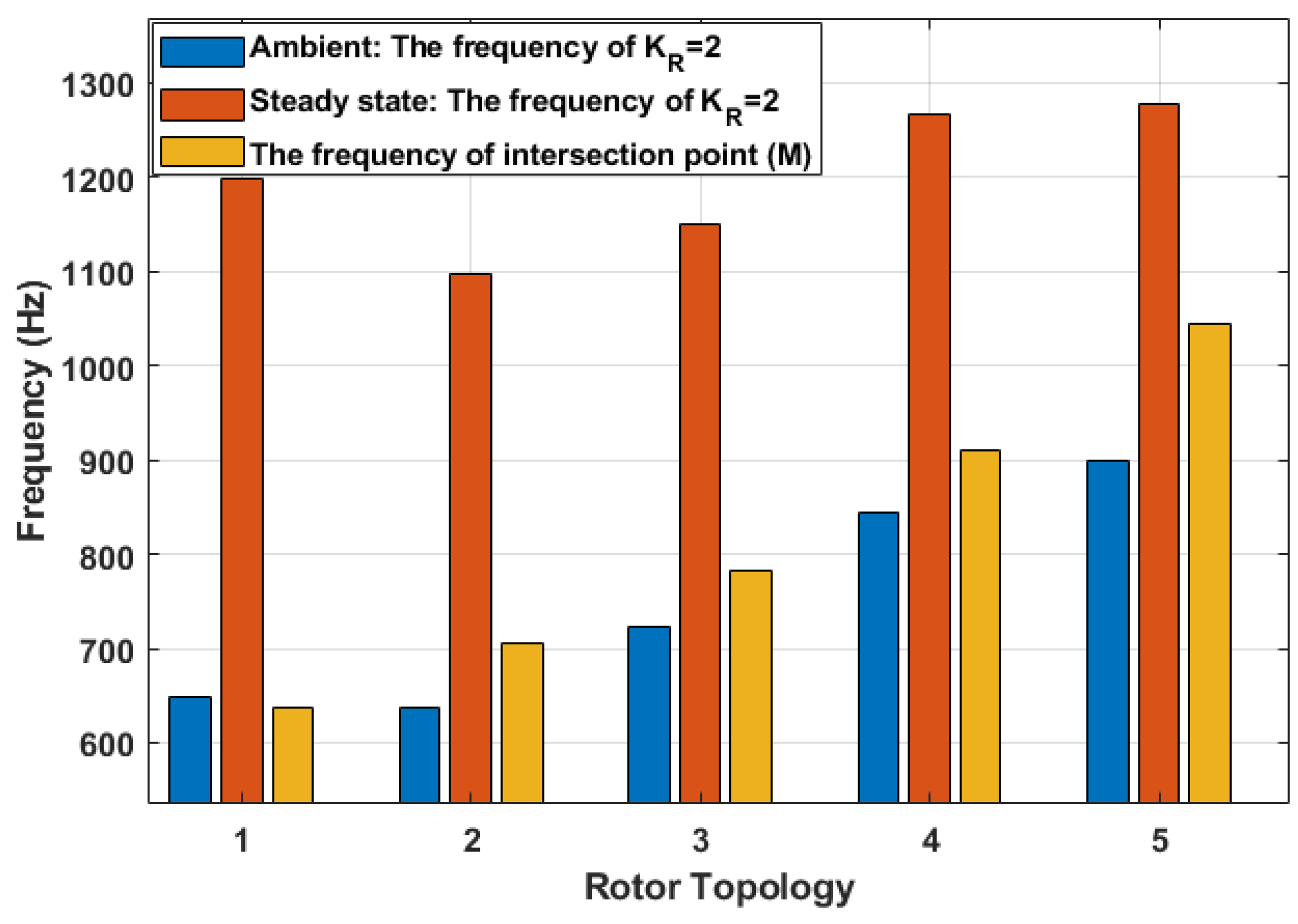
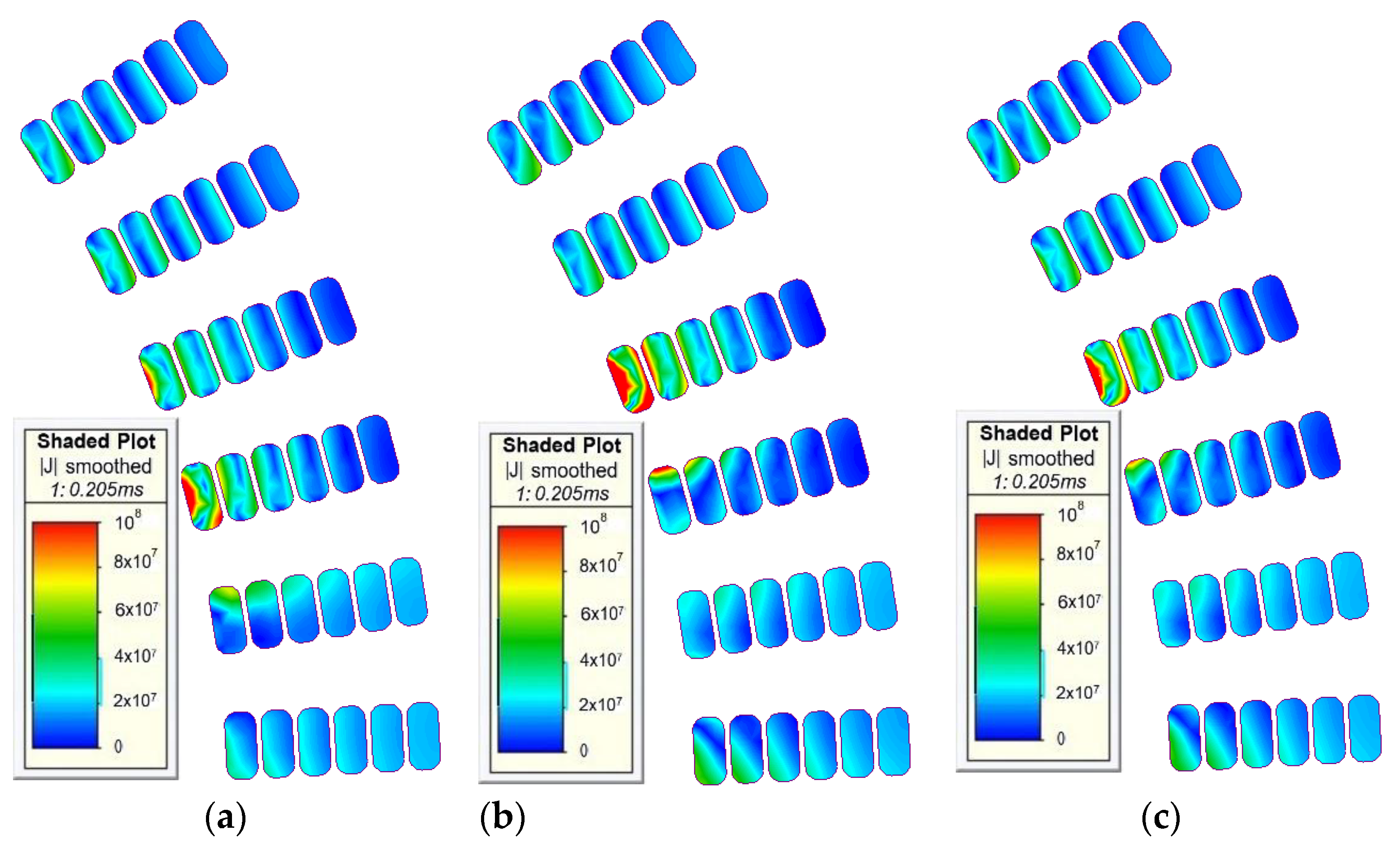
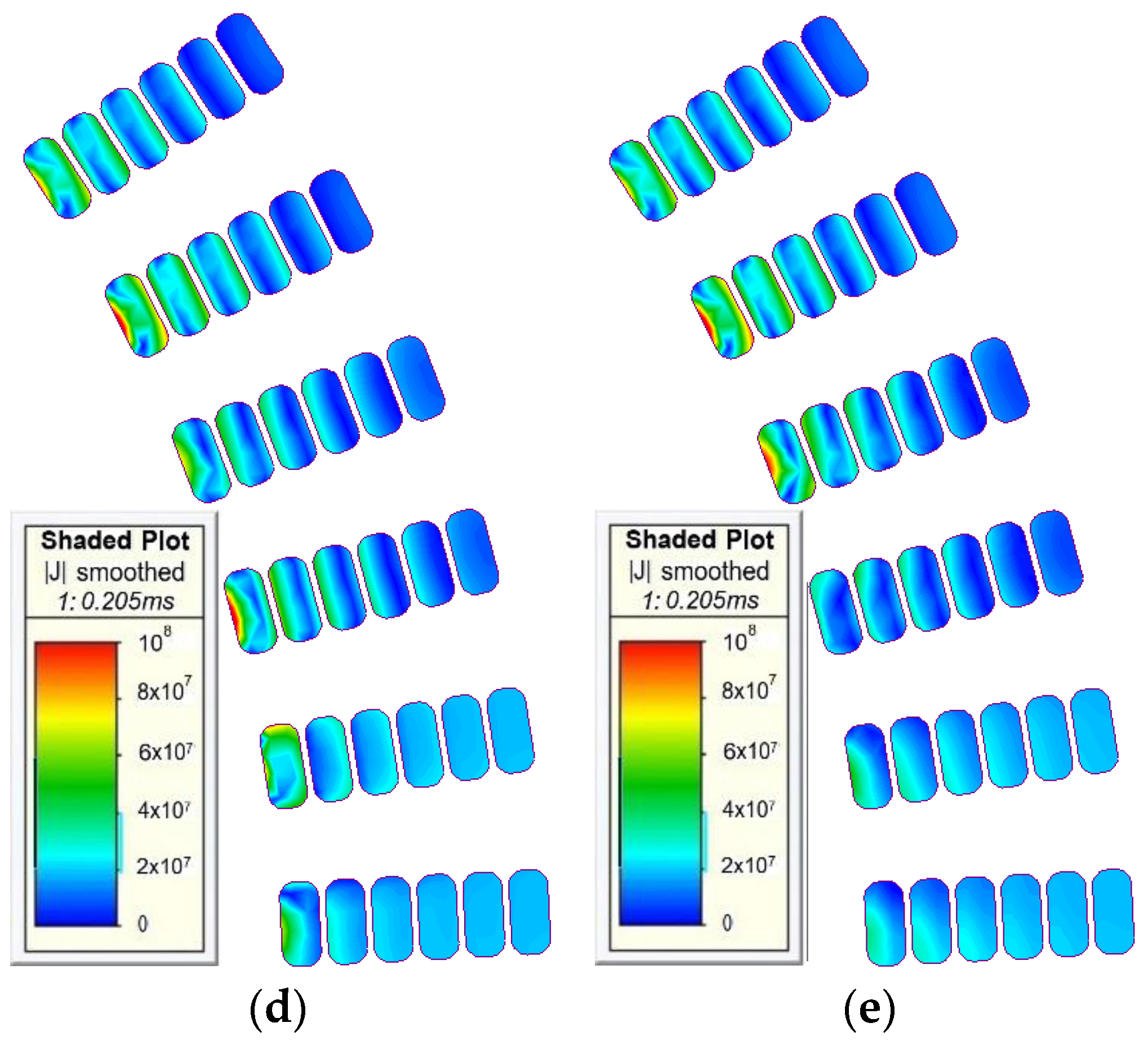
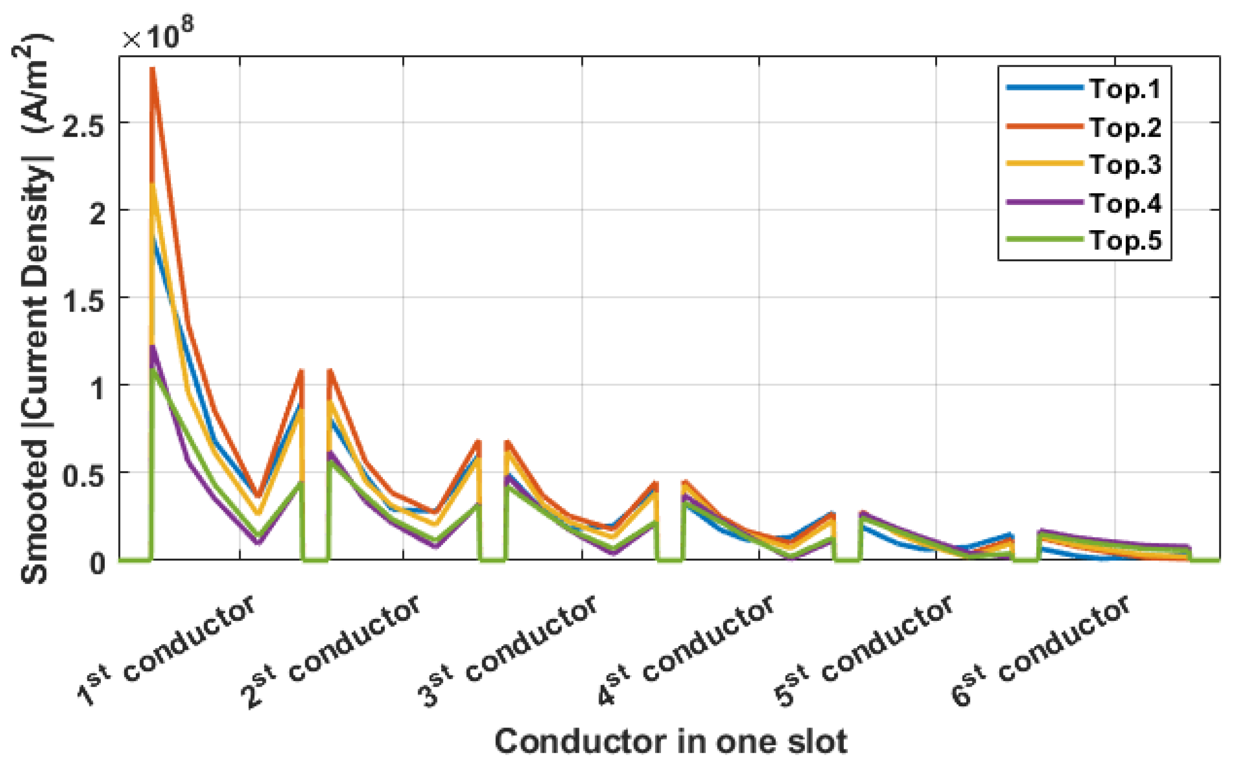
5. Analysis of Losses versus Rotor Topologies
5.1. Ohmic Losses versus Different Rotor Topologies
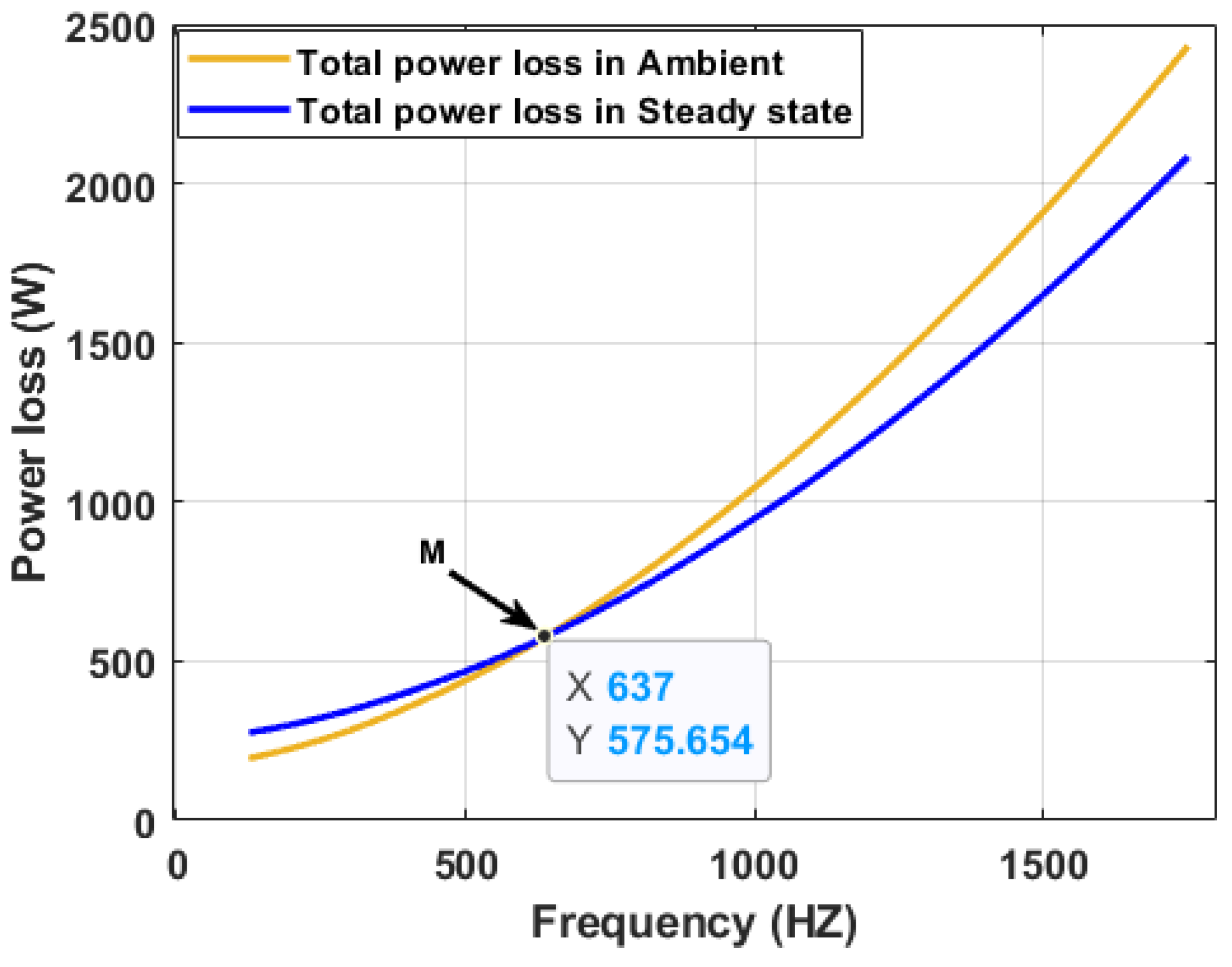
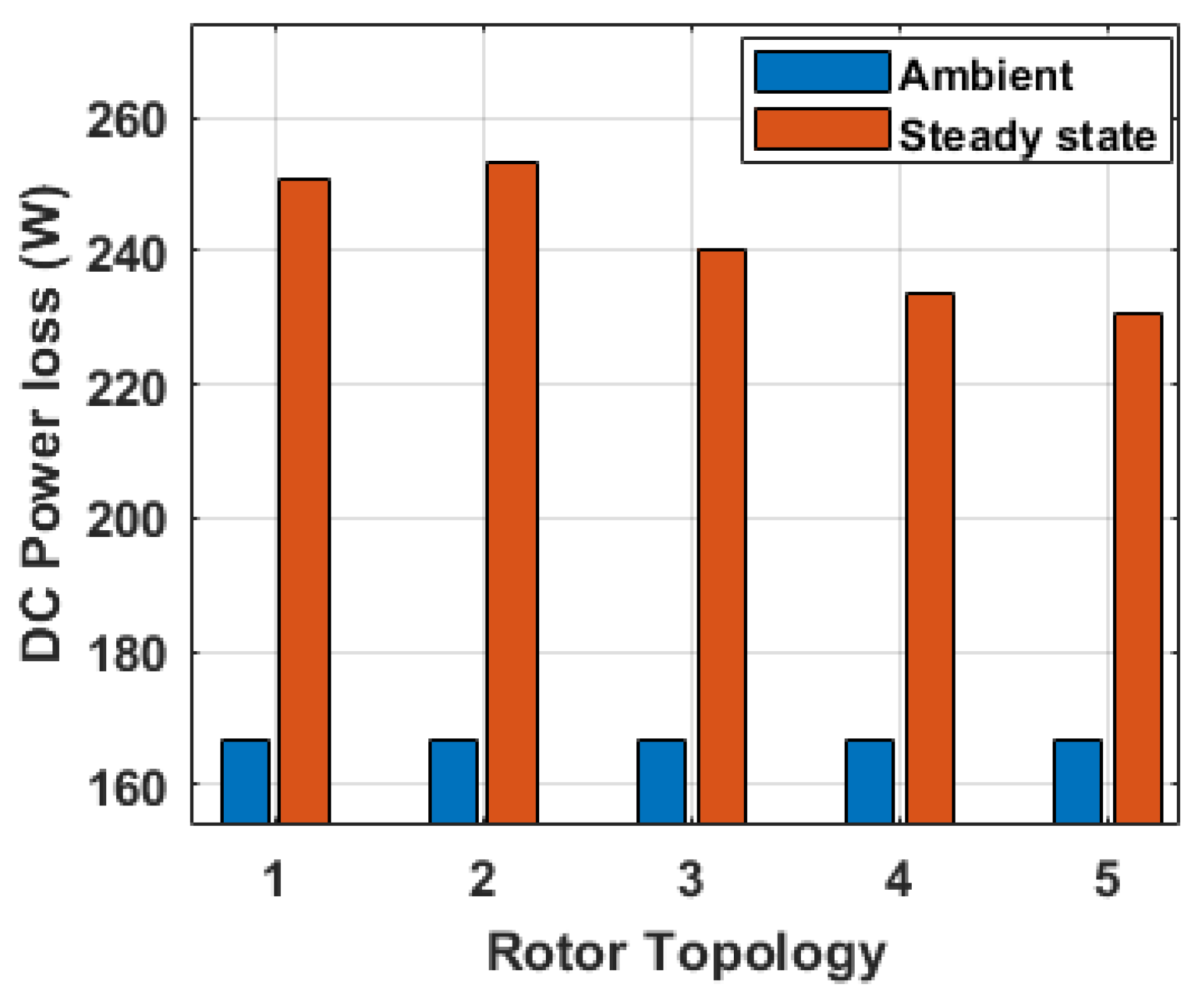
5.2. Analysis of Ohmic Losses versus Both Temperature and Rotor Topologies
6. Conclusions
- (1)
- Evaluating the loss performance of the considered motor at an assumed ambient temperature of 20 °C via the electromagnetic FEA model.
- (2)
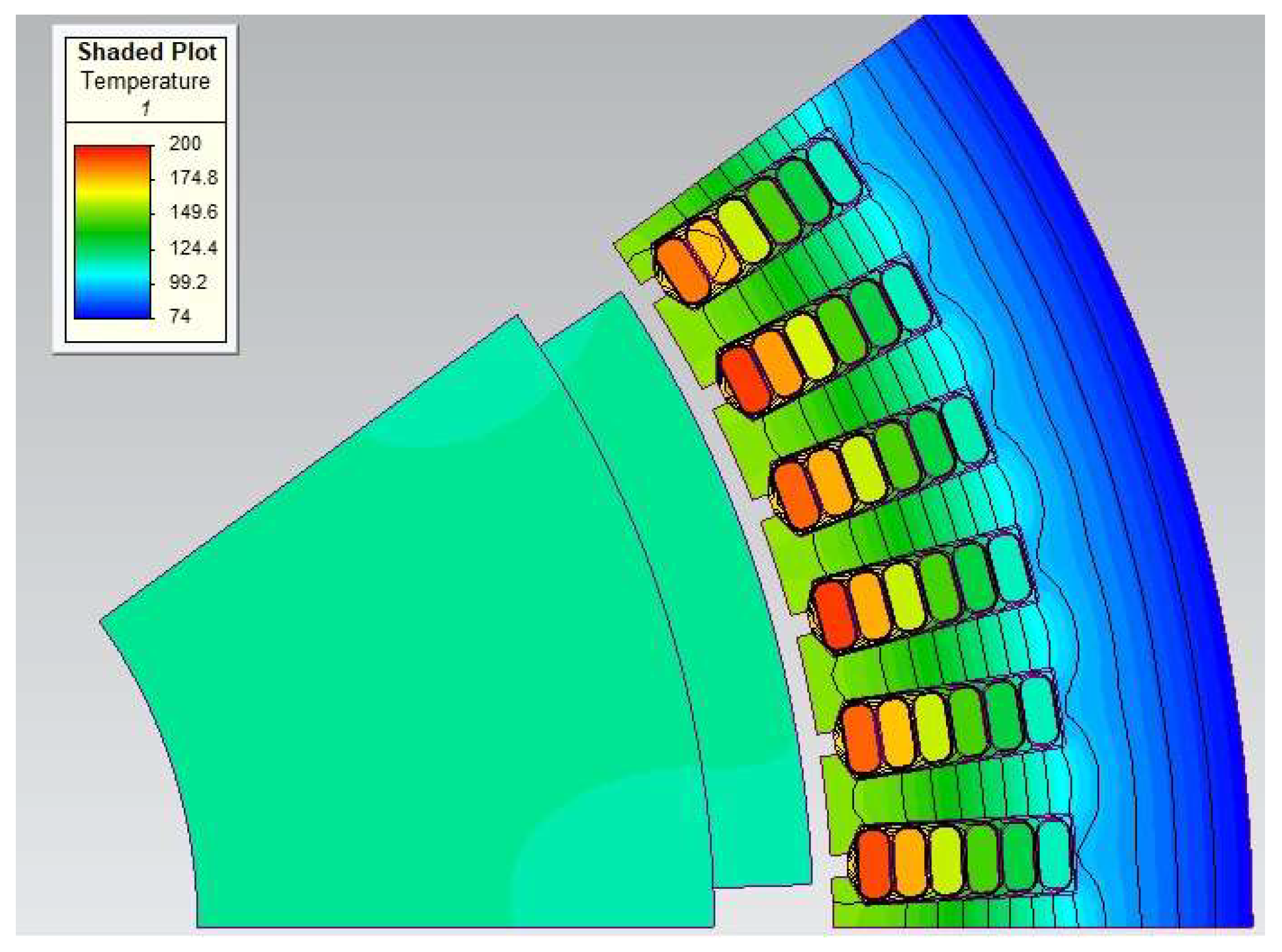
- Evaluating the temperature map of the considered motor via the thermal FEA model considering the losses determined in (1).
- (3)
- Evaluating the loss performance of the considered motor via the electromagnetic FEA model at the temperatures determined in (2).
- (4)
- Repeating the above tasks for motors featuring different rotor topologies.
Author Contributions
Funding
Conflicts of Interest
References
- Ranjbar, H.; Sharifzadeh, M. Electrification of Transportation. In Industry 4.0 Vision for the Supply of Energy and Materials: Enabling Technologies and Emerging Applications; Wiley: Hoboken, NJ, USA, 2022; pp. 269–296. [Google Scholar] [CrossRef]
- Swaminathan, N.; Reddy, S.R.P.; Rajashekara, K.; Haran, K.S. Flying Cars and eVTOLs—Technology Advancements, Powertrain Architectures and Design. IEEE Trans. Transp. Electrif. 2022, 1. [Google Scholar] [CrossRef]
- Esmaeili, M.; Anvari-Moghaddam, A.; Muyeen, S.M.; Perić, V.S. On the Role of Renewable Energy Policies and Electric Vehicle Deployment Incentives for a Greener Sector Coupling. IEEE Access 2022, 10, 53873–53893. [Google Scholar] [CrossRef]
- Kadavergu, A.; Anuradha, K.; Kumari, N.K. Development of Motor Gear Powertrain System for Electrical Vehicle. In 2021 Innovations in Power and Advanced Computing Technologies (i-PACT); IEEE: Manhattan, NY, USA, 2021; pp. 1–6. [Google Scholar] [CrossRef]
- Pastura, M.; Nuzzo, S.; Immovilli, F.; Toscani, A.; Rumi, A.; Cavallini, A.; Franceschini, G.; Barater, D. Partial Discharges in Electrical Machines for the More Electric Aircraft—Part I: A Comprehensive Modeling Tool for the Characterization of Electric Drives Based on Fast Switching Semiconductors. IEEE Access 2021, 9, 27109–27121. [Google Scholar] [CrossRef]
- Nuzzo, S.; Barater, D.; Gerada, C.; Vai, P. Hairpin Windings: An Opportunity for Next-Generation E-Motors in Transportation. IEEE Ind. Electron. Mag. 2021, 2–10. [Google Scholar] [CrossRef]
- Pyrhonen, J.; Jokinen, T.; Hrabovcova, V. Design of Rotating Electrical Machines; John Wiley & Sons: Hoboken, NJ, USA, 2013. [Google Scholar]
- Rosskopf, A.; Brunner, C. Enhancing Litz Wire Power Loss Calculations by Combining a Sparse Strand Element Equivalent Circuit Method With a Voronoi-Based Geometry Model. IEEE Trans. Power Electron. 2022, 37, 11450–11456. [Google Scholar] [CrossRef]
- Dimier, T.; Cossale, M.; Wellerdieck, T. Comparison of Stator Winding Technologies for High-Speed Motors in Electric Propulsion Systems. In Proceedings of the 2020 International Conference on Electrical Machines (ICEM), Gothenburg, Sweden, 23–26 August 2020; pp. 2406–2412. [Google Scholar] [CrossRef]
- Popescu, M.; Goss, J.; Staton, D.A.; Hawkins, D.; Chong, Y.C.; Boglietti, A. Electrical Vehicles—Practical Solutions for Power Traction Motor Systems. IEEE Trans. Ind. Appl. 2018, 54, 2751–2762. [Google Scholar] [CrossRef] [Green Version]
- Zhao, Y.; Li, D.; Pei, T.; Qu, R. Overview of the rectangular wire windings AC electrical machine. CES Trans. Electr. Mach. Syst. 2019, 3, 160–169. [Google Scholar] [CrossRef]
- Soltani, M.; Nuzzo, S.; Barater, D.; Franceschini, G. A Multi-Objective Design Optimization for a Permanent Magnet Synchronous Machine with Hairpin Winding Intended for Transport Applications. Electronics 2021, 10, 3162. [Google Scholar] [CrossRef]
- Soltani, M.; Nuzzo, S.; Barater, D.; Franceschini, G. Considerations on the Preliminary Sizing of Electrical Machines with Hairpin Windings. In Proceedings of the 2021 IEEE Workshop on Electrical Machines Design, Control and Diagnosis (WEMDCD), Modena, Italy, 8–9 April 2021; pp. 46–51. [Google Scholar]
- Selema, A.; Ibrahim, M.N.; Sergeant, P. Mitigation of High-Frequency Eddy Current Losses in Hairpin Winding Machines. Machines 2022, 10, 328. [Google Scholar] [CrossRef]
- Islam, M.S.; Husain, I.; Ahmed, A.; Sathyan, A. Asymmetric Bar Winding for High-Speed Traction Electric Machines. IEEE Trans. Transp. Electrif. 2020, 6, 3–15. [Google Scholar] [CrossRef]
- Preci, E.; Nuzzo, S.; Valente, G.; Gerada, D.; Barater, D.; Degano, M.; Buticchi, G.; Gerada, C. Segmented Hairpin Topology for Reduced Losses at High-Frequency Operations. IEEE Trans. Transp. Electrif. 2022, 8, 688–698. [Google Scholar] [CrossRef]
- Liu, C.; Xu, Z.; Gerada, D.; Li, J.; Gerada, C.; Chong, Y.C.; Popescu, M.; Goss, J.; Staton, D.; Zhang, H. Experimental Investigation on Oil Spray Cooling With Hairpin Windings. IEEE Trans. Ind. Electron. 2020, 67, 7343–7353. [Google Scholar] [CrossRef]
- Reinap, A.; Andersson, M.; Márquez-Fernández, F.J.; Abrahamsson, P.; Alaküla, M. Performance Estimation of a Traction Machine with Direct Cooled Hairpin Winding. In Proceedings of the 2019 IEEE Transportation Electrification Conference and Expo (ITEC), Detroit, MI, USA, 19–21 June 2019; pp. 1–6. [Google Scholar] [CrossRef]
- Zhang, F.; Gerada, D.; Xu, Z.; Liu, C.; Zhang, H.; Zou, T.; Chong, Y.C.; Gerada, C. A Thermal Modeling Approach and Experimental Validation for an Oil Spray-Cooled Hairpin Winding Machine. IEEE Trans. Transp. Electrif. 2021, 7, 2914–2926. [Google Scholar] [CrossRef]
- Venturini, G.; Volpe, G.; Popescu, M. Slot Water Jacket Cooling System for Traction Electrical Machines with Hairpin Windings: Analysis and Comparison. In Proceedings of the 2021 IEEE International Electric Machines & Drives Conference (IEMDC), Hartford, CT, USA, 17–20 May 2021; pp. 1–6. [Google Scholar] [CrossRef]
- Formula SAE Rules 2021 Version 1.0. Available online: www.fsaeonline.com/cdsweb/gen/DocumentResources.aspx (accessed on 1 July 2022).
- Huang, X.; Jiang, B.; Alhallak, M.N.; Nategh, S.; Liu, Y.; Boglietti, A. Experimental Evaluation of Conductor Insulations Used in E-mobility Traction Motors. In Proceedings of the 2021 IEEE Workshop on Electrical Machines Design, Control and Diagnosis (WEMDCD), Modena, Italy, 8–9 April 2021; pp. 249–253. [Google Scholar] [CrossRef]


| Parameters | Round Winding | Hairpin Optimal Design |
|---|---|---|
| Mechanical power (KW) | 40 | 40 |
| DC link voltage (V) | 600 | 600 |
| Base speed (rpm) | 12,740 | 12,740 |
| Torque (Nm) | 30 | 30 |
| Surface current density (A/mm2) | 13 | 13 |
| Linear current density (A/mm) | 70 | 70 |
| Peak current (A) | 140 | 63.7 |
| Fill factor | 60% | 85% |
| Pole number | 6 | 8 |
| slot/pole/phase | 1 | 4 |
| Axial length | 65 | 26 |
| Conductors/slot | 11 | 6 |
| Rotor radius | 45 | 59 |
| Tooth width | 10 | 1.635 |
| Yoke thickness | 14 | 13.35 |
| Outer radius | 85 | 80.6 |
| Power loss (kW) | 2 | 1.42 |
| Efficiency | 95.2% | 96.6% |
| Volume power density (MW/m3) | 16.75 | 74.4 |
| Volume torque density (kNm/m3) | 13.21 | 55.76 |
| Stator winding | Distributed, full-pitch, single layer | |
| Core material | M330-50A | |
| PM material | NdfeB-N28AH | |
| Parameter | New Optimal Motor | The Motor in [12] |
|---|---|---|
| Fill factor (%) | 65 | 85 |
| Outer stator diameter (mm) | 173.27 | 161.2 |
| Rotor diameter (mm) | 124.8 | 118 |
| Axial length (mm) | 26 | 26 |
| Slot− pole− phase | 2 | 4 |
| Pole number | 10 | 8 |
| Number of conductors per slot | 6 | 6 |
| Max. frequency (Hz) | 1061.7 | 849.33 |
| Efficiency (%) | 96.1 | 96.6 |
| Power density (MW/m3) | 74.1 | 74.5 |
Publisher’s Note: MDPI stays neutral with regard to jurisdictional claims in published maps and institutional affiliations. |
© 2022 by the authors. Licensee MDPI, Basel, Switzerland. This article is an open access article distributed under the terms and conditions of the Creative Commons Attribution (CC BY) license (https://creativecommons.org/licenses/by/4.0/).
Share and Cite
Soltani, M.; Nuzzo, S.; Barater, D.; Franceschini, G. Investigation of the Temperature Effects on Copper Losses in Hairpin Windings. Machines 2022, 10, 715. https://doi.org/10.3390/machines10080715
Soltani M, Nuzzo S, Barater D, Franceschini G. Investigation of the Temperature Effects on Copper Losses in Hairpin Windings. Machines. 2022; 10(8):715. https://doi.org/10.3390/machines10080715
Chicago/Turabian StyleSoltani, Mohammad, Stefano Nuzzo, Davide Barater, and Giovanni Franceschini. 2022. "Investigation of the Temperature Effects on Copper Losses in Hairpin Windings" Machines 10, no. 8: 715. https://doi.org/10.3390/machines10080715
APA StyleSoltani, M., Nuzzo, S., Barater, D., & Franceschini, G. (2022). Investigation of the Temperature Effects on Copper Losses in Hairpin Windings. Machines, 10(8), 715. https://doi.org/10.3390/machines10080715