Abstract
In the switch rail section of a high-speed turnout, the wheel–rail lateral impact of the forepart of the curved switch rail is the most important factor affecting the passing performance. In order to reduce the lateral impact and improve the passing safety, a complete vehicle–track multi-body dynamics model is devised in this paper. The variation of the wheel–rail relationship when the train passes through is analyzed. The lateral force and derailment coefficient are calculated under different parameters, and the wear index is also calculated under some working conditions. The results show that properly reducing the lateral damping of the curved switch rail can effectively reduce the wheel–rail lateral force and derailment coefficient of this section, while keeping the track shape undamaged. The optimization of rail cant design plays an important role in alleviating lateral wheel–rail impact. Decreasing the height reduction of the switch rail is helpful to optimize the lateral force of the forepart of the curved switch rail. The selection of a suitable cutting mode for switch blade and reasonable control of the wheel–rail impact angle as well as passing speed have positive effects on controlling the lateral wheel–rail impact of the forepart of the curved switch rail.
1. Introduction
In a railway line, there are usually multiple tracks in the switch area where the wheel–rail relationship is more complex. The turnout system is often studied as the weak link of the track, which plays a controlling role in the passing capacity. When the wheelset passes through the switch rail section, the wheel–rail system will produce a drastic lateral impact because the flange root of the outer wheel inevitably touches and impacts the switch rail, thus causing the lateral force of the outer wheel–rail to increase suddenly [1,2]. When the train enters the turnout in reverse direction, the lateral acceleration of the vehicle body in the switch rail section controls the riding quality [3]. The wheel–rail lateral impact is dominant in this area [4,5].
According to relevant papers, the stiffness and damping of the turnout-related structures and components have an important effect on its performance. In particular, Alejandro et al. [6] performed a probabilistic assessment and found that a higher damping of the primary suspension leads to higher accelerations in the turnout. Moreover, a study by Li et al. [7] shows that increasing the vertical damping of the air spring appropriately can effectively suppress the dynamic interaction between the train and the turnout. The results for a numerical optimization method show that less-stiff USPs (under sleeper pads) with higher damping can reduce the low-frequency forces caused by the low-frequency component of the wheel force [8]. Zhu et al. [9] established a simplified model of the lateral vibration of the track structure under an impact load. By changing the lateral stiffness of the rail fasteners and track bed, the effects on rail wear and lateral vibration characteristics of the wheel–rail system were observed. In terms of the study by Antonio et al. [10], greater values of track stiffness led to higher wheel–rail dynamic loads generated in a turnout. Similarly, an increase in the track stiffness causes an increase in the vertical and normal forces, and thus an increase in the wear process [11]. Furthermore, a higher ballast stiffness leads to a higher acceleration magnitude [6]. Grossoni et al. [12] indicated that a reduction in the wheel–rail impact load would come from optimizing the support stiffness. Jiang et al. [13] conducted an experimental study on the floating slab track in the turnout areas. The results showed that the measured inherent frequency and the working frequency of the high stiffness area with a denser distribution of isolators were higher. Chen et al. [14] studied the reasonable stiffness of the ballastless track turnout of a 250 km/h passenger dedicated line using the method of theoretical analysis. As for the high-speed turnout, the research on the reasonable stiffness and its distribution optimization in the turnout area is mainly focused on the vertical stiffness, while the distribution of lateral stiffness in the turnout area and its influence on high-speed operation are not clear yet [15].
In order to optimize the stress condition of the track, the rail on the ordinary track is usually set with a certain value for the rail cant, as the rail top slope is set on the turnout track. The optimization of its setting is expected to improve the passing performance of the turnout. According to the relative experimental and numerical study of Sun et al. [16], re-profiling the rail and adjusting the rail cant can eliminate the carbody hunting instability, but it is not an economic approach. A relatively effective method to solve this problem is to increase the hunting frequency and minimal damping ratio by optimizing the suspension parameters. There are other simulation results that show that keeping the rail cant at about 1:40 and reducing the track gauge can improve the carbody hunting stability of the electric locomotive [17]. Based on the trace line method and 3D non-Hertzian rolling contact theory, Qian et al. [18] studied the static wheel–rail contact characteristics of a high-speed railway with different wheel–rail matching under different rail cant conditions. Wang et al. [19] studied the outer rail wear of a small radius curve in urban rail lines and analyzed the influence of rail cant on outer rail wear. Especially for the rail track with a radius of 375 m, it is suggested to use a cant value of 1:40 on the curve as it can greatly reduce wheel wear [20]. Wang et al. [21] established a heavy haul vehicle–track dynamic model and found that increasing the rail cant of the inner rail to 1:20 is more effective to reduce the curve rail wear than setting a certain value for inadequate superelevation. The investigation of Wu et al. [22] indicated that the reverse rail cant can increases the risk of a rail rollover derailment. Ghosh et al. [23] studied the effect of rail cant on the stress distribution of a concrete sleeper using the method of static test. The results from the parametric study of Mojumder et al. [24] indicate that the effects of the rail cant angle and rail stiffness were not high enough for crack initiation. Wang et al. [25] established the train-track coupled dynamic model by using the multi-body dynamics software, UM, and analyzed the dynamic performance of heavy haul trains on curved tracks under different rail cant conditions. The results showed that the rail cant of 1:20 was better than 1:40.
Studies have shown that the design position and size of the height reduction of the switch rail will directly affect the distribution and transition of the wheel load between the switch rail and stock rail [26]. Hence, it has an important influence on the riding quality of a train passing through the turnout. Through the experiment and simulation analysis of the height reduction of the switch rail for the 1:42 turnout, it was found that if the height reduction exceeded the design limit, the amplitude of the hunting motion would become larger and even cause the swaying of the train [27,28].
Therefore, according to the existing research results, it could be reasonably inferred that the lateral stiffness and damping parameters of the curved switch rail, as well as the design of the rail cant and the height reduction may affect the lateral impact when the train passes through the diverging route of the turnout. In addition, the wheel–rail impact angle and the cutting mode for the switch blade are closely related to the irregularity of the turnout diverging route, which will have a great influence on the wheel–rail lateral impact of the forepart of the curved switch rail. The above problems are expected to be alleviated by optimizing the related structures and parameters. In this paper, the factors affecting the wheel–rail lateral impact of the forepart of the curved switch rail are studied and discussed comprehensively, aiming to help with the design of the turnouts and curved switch rails in the future.
2. Modelling and Calculation
2.1. Vehicle–Track Dynamics Model
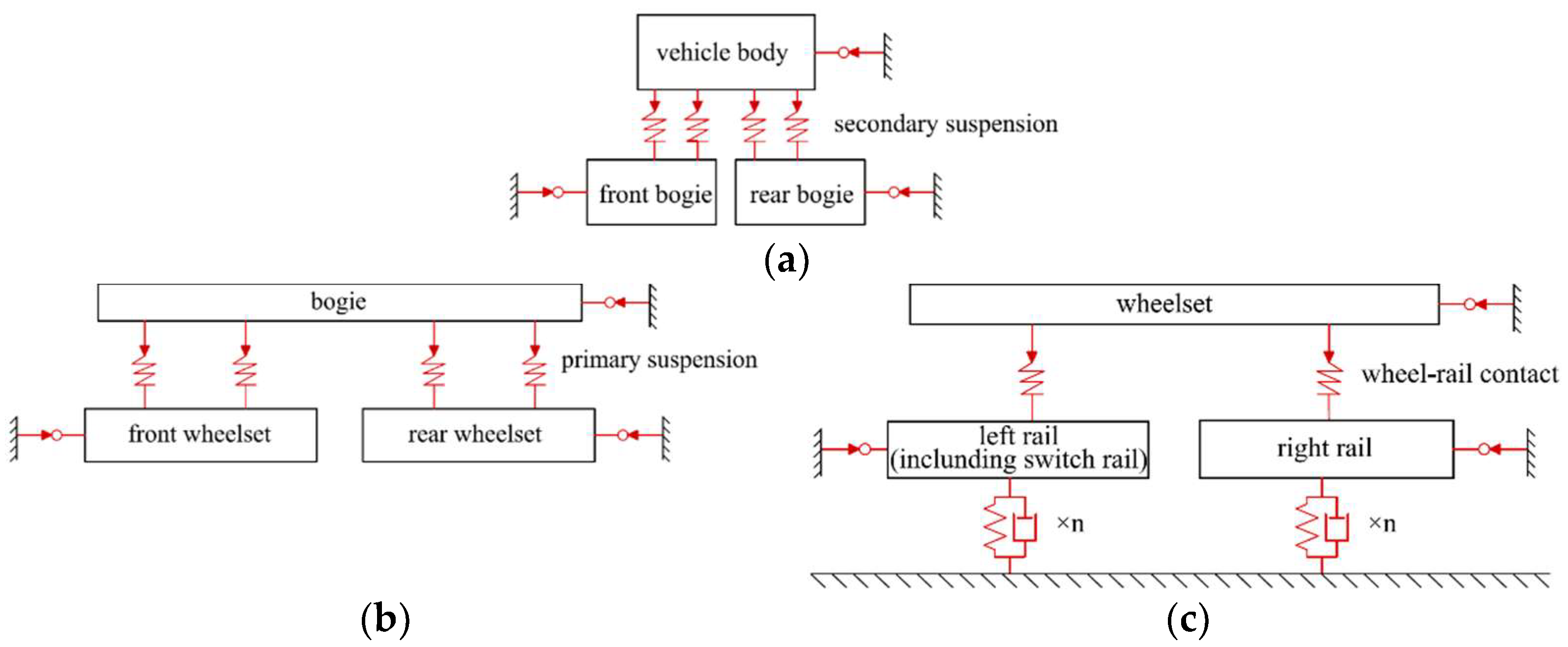
A complete vehicle–track model is established by using the multi-body dynamics method. The substructure modelling method is applied to establish the model structure, as shown in Figure 1. The vehicle body and bogies are connected by secondary suspensions, while the bogies and wheelsets are connected by primary suspensions. The flexible body of the track structure is established by using solid elements, and is connected to the global reference system by discrete spring-damping elements.
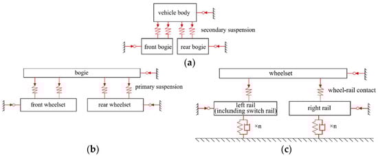
Figure 1.
The topological graph of the model. (a) Structure of the vehicle; (b) substructure—bogie;
(c) substructure—wheelset.
Because of the existence of the switch rail structure, the outer rail of the guide curve has a variable cross-section within a certain length range. In order to model the rail with variable sections, taking 1:42 turnout as an example, 12 sections are selected in its length range. Six of these sections are shown in Figure 2. Using the unified coordinate system, the outer contour of each selected section is discretized into a series of separate points. Its coordinates are then written into the section files according to the required program language rules. Then, the rail with variable cross-sections can be formed by the interpolation algorithm. The Bézier curve is used in the interpolation, and n + 1 control points can determine an n-th order Bézier curve [29,30]. It is described as follows:
where is the interpolation control point and is a dimensionless parameter. When equals 0 or 1, it corresponds to the first and last control point, respectively. is the Bernstein polynomial, whose expression is as follows:
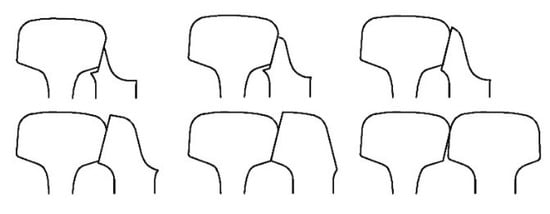
Figure 2.
Part of the profiles of the rail with a variable cross-section.
The vehicle parameters and track parameters are set according to the related literatures [31]. The stiffness and damping parameters [32] of the track are shown in Table 1. It should be pointed out that the parameters of the fastener stiffness and damping mentioned in this paper are not the parameters of a specific track component, but refer to the parameters of the spring-damping element between the rail and the global reference system, which is the equivalent parameter under the comprehensive influence of multiple factors, such as the rail pad and sleeper condition. For some specific parameters of a specific part, it is necessary to use more detailed models and experiments on the basis of this study.

Table 1.
The stiffness and damping parameters of the track.
The track alignment parameters refer to the design drawings of curved switch rail and guide curve of the 1:42 turnout. The curve is a circular curve with a radius of 5000 m and a length of 79.754 m. A 50 m straight line is set before the turnout section. According to the geometric relationship, the theoretical starting point of the curved switch rail in the model is located at 50.000 m, while the actual starting point is located at 53.026 m. And the actual starting point of the guide curve is located at 56.083 m.
2.2. Calculation of Wheel–Rail Force
The Hertzian method [33] is adopted for the calculation of the normal force. For the calculation of the creep force, the simplified theory of the Kalker linear creep theory, FASTSIM, can meet the requirement of accuracy, and the calculation speed is faster than the CONTACT theory [34], so this method was adopted in this paper. Detailed calculation methods can be seen in the references.
We set the vehicle of the model to pass through the diverging route of the turnout at a speed of 160 km/h, and calculated the wheel–rail lateral force of the forepart of the curved switch rail. Taking the calculation results of the first wheelset, the typical calculation condition of the wheel–rail lateral force of the outer rail is shown in Figure 3.
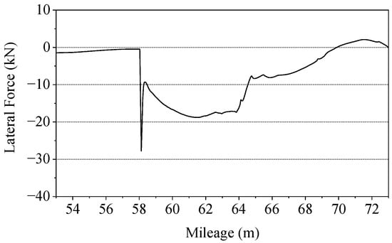
Figure 3.
The typical working condition.
By observing the calculation result and the wheel–rail contact state at the corresponding position, it can be seen that when the vehicle enters the curve (53.0 m), the wheel flange gradually approaches the switch rail until contact impact occurs (53.0–58.1 m). Then, it continues to move forward against the curved switch rail (58.1–64.8 m). After traveling for a certain distance, the flange and the curved switch rail gradually separate (64.8–73.0 m).
3. Analysis and Discussion
3.1. Influence of Lateral Damping and Stiffness
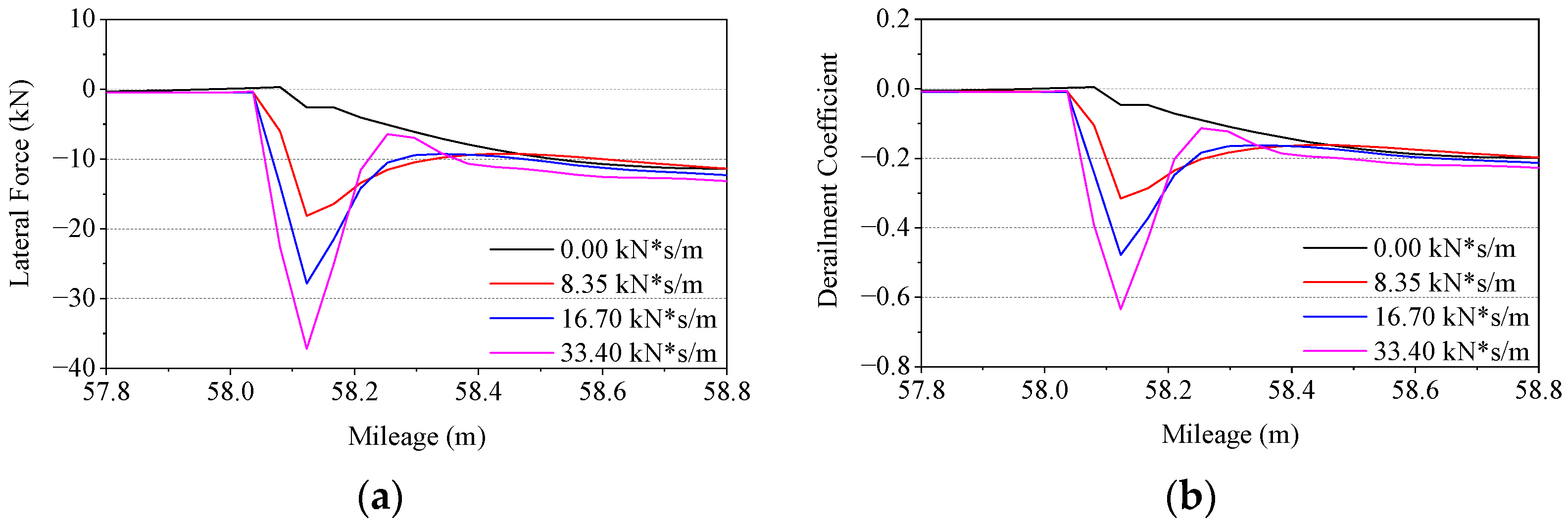
In order to study the influence of lateral damping on the wheel–rail impact in the turnout area, the lateral damping of the curved switch rail fastener is changed in the model while keeping the lateral stiffness of 25 kN/mm unchanged. The wheel–rail lateral force and derailment coefficient of the first wheelset passing through the forepart of the curved switch rail under different fastener lateral damping conditions are calculated. Note that the derailment coefficient is defined as the ratio of the wheel–rail lateral force to the vertical force. The calculation results are shown in Table 2 and Figure 4 and Figure 5a.
Table 2.
Extreme values of calculation results under different lateral damping conditions.
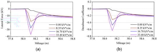
Figure 4.
Wheel–rail lateral force and derailment coefficient under different lateral damping. (a) lateral force; (b) derailment coefficient.
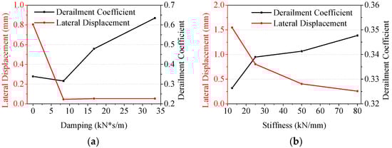
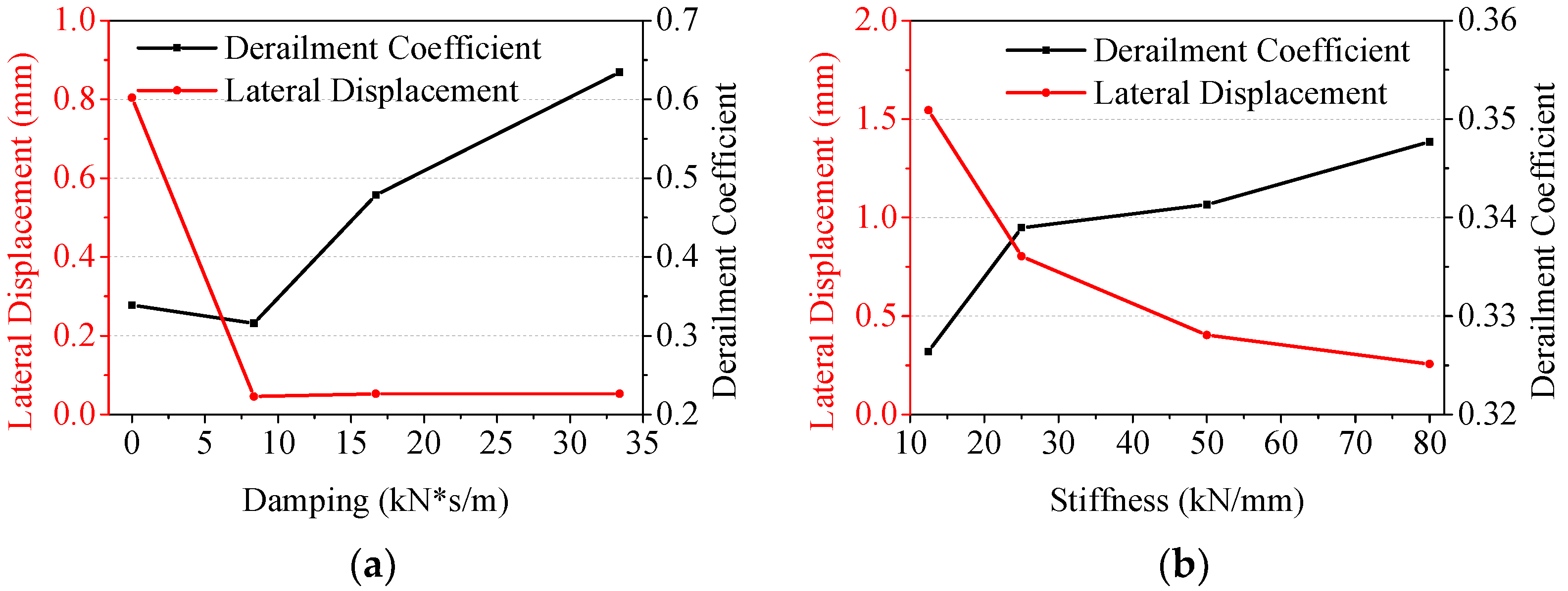
Figure 5.
Chart of extreme values of calculation results under different lateral damping and stiffness conditions. (a) Results under different damping conditions; (b) results under different stiffness conditions.
According to the calculation and statistics, except for the undamped condition, with the increase in the lateral support damping of the switch rail, the lateral force and derailment coefficient gradually increases while the lateral displacement of the rail changes slightly. Considering the most unfavorable working condition of the lateral displacement, the case of zero damping is calculated and the results are shown in Figure 5b. It is shown that with the increase in the lateral support stiffness of the switch rail, the derailment coefficient gradually increases while the lateral displacement of the rail decreases.
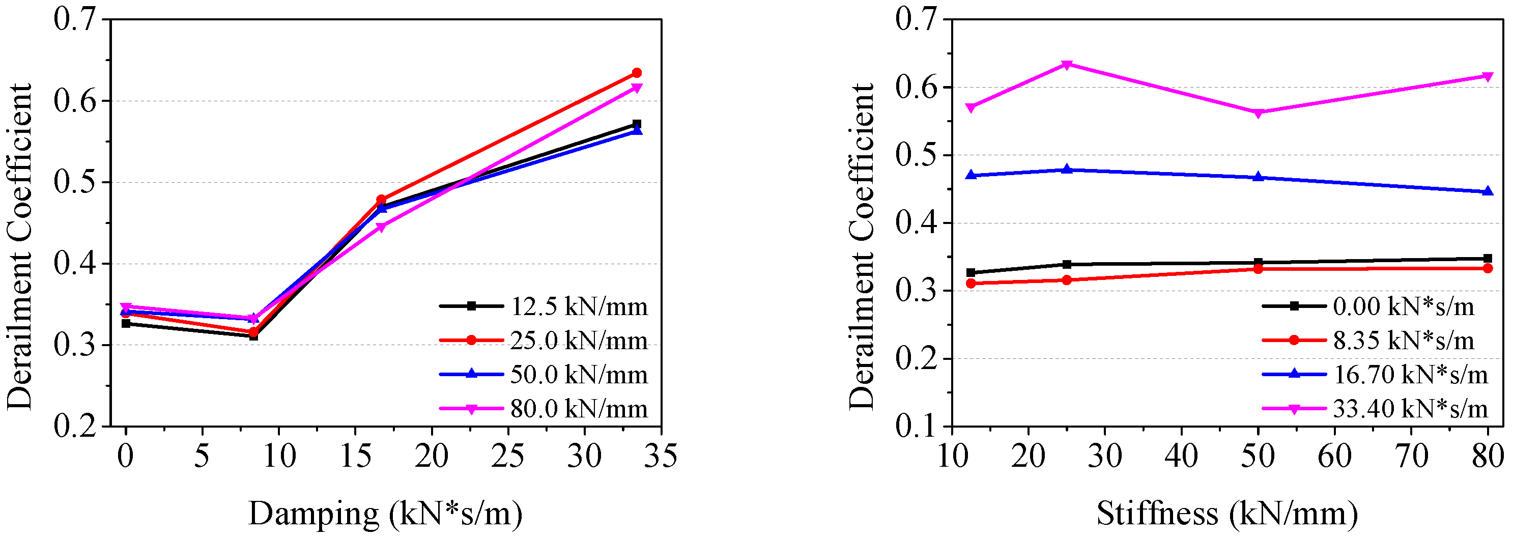
The calculation results of the derailment coefficient are summarized, and the statistical charts of the calculation results are shown in Figure 6.
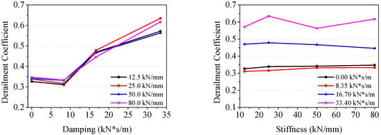
Figure 6.
Charts of extreme values of the calculation results.
In terms of the calculation results, if we leave out the undamped condition, the increase in lateral damping will increase the derailment coefficient, while the stiffness change has no obvious influence on it. In engineering practice, adjusting the track damping can usually be achieved by changing the structure of the fasteners. For example, under-rail pads of different materials can affect the dynamic characteristics of the track [35].
3.2. Influence of Rail Cant
In order to reduce the wheel–rail lateral impact of the outer rail, more use of the conical degree of the wheel is tried to make. For the present 1:42 turnout, the switch rail is not provided with a rail cant, but is designed with a rail top slope. To change the size of the slope, the profile of the rail needs to be redesigned. In order to be able to use the current profile design, this chapter substitutes rail cant for it instead.
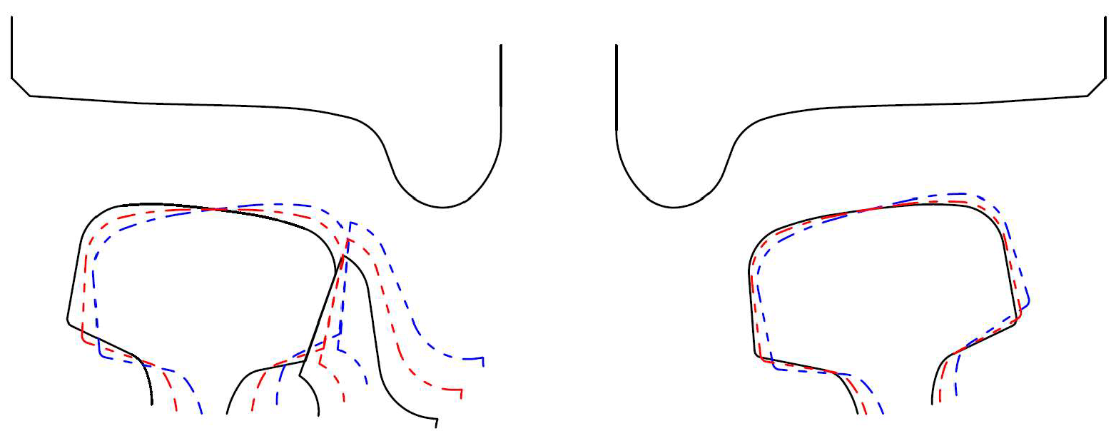
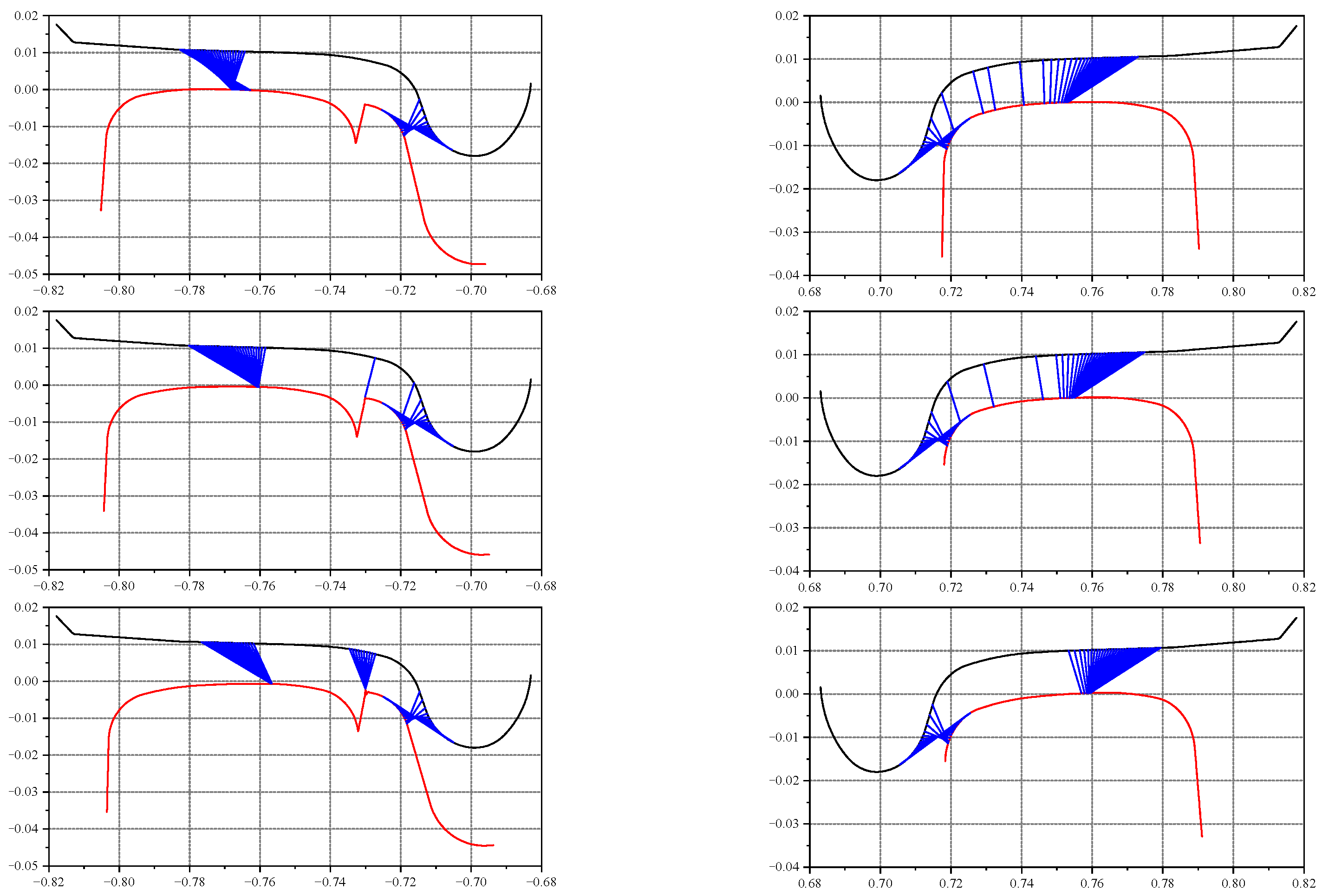
If the wheelset forms a certain difference of the diameters of the rolling circle of the inner and outer wheel on the curve, the vehicle may well pass more smoothly. Therefore, an attempt is made to change the rail cant of the inner and outer rails to make the outer wheel–rail contact point move inward, that is, to increase the actual rolling circle radius. On the other hand, the inner wheel–rail contact point moves outward, that is, the actual rolling circle radius is decreased. The schematic diagram is shown in Figure 7 and Figure 8. By observing the calculation results of wheel–rail contact points before and after changing the rail cants, it can be seen that the change of rail cants can cause the change of wheel–rail contact points as expected.
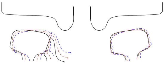
Figure 7.
Rail cant adjustment of a typical cross-section (the angle is 5 times enlarged for illustration).
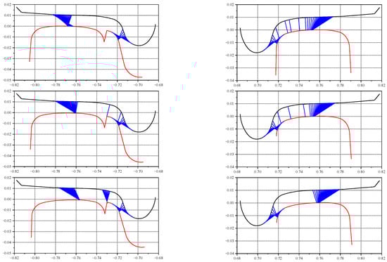
Figure 8.
Wheel–rail contact position change of a typical cross-section.
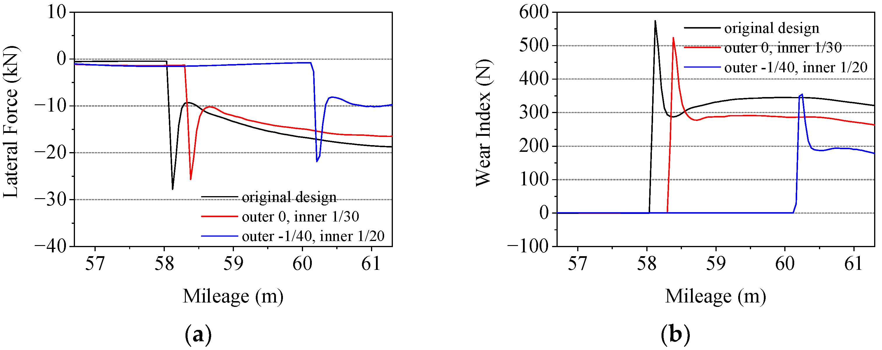
Based on the original design, two different working conditions are taken for comparative analysis. The rail cant of the outer rail is set as 0 and −1/40, and that of the inner rail is set as 1/30 and 1/20 respectively. The calculation results of wheel–rail lateral force is shown in Figure 9a. The results show that the change of rail cant significantly affects the wheel–rail impact of the forepart of the curved switch rail. Through the optimized design, the wheel–rail lateral impact force is decreased by 21.3%. Moreover, the location of peak lateral impact between wheel and rail has also changed. The impact point moves backward to the thicker section of the switch rail, which is beneficial to the stress bearing of the switch rail.
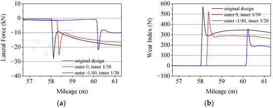
Figure 9.
Calculation results of wheel–rail lateral force and wear index under different rail cant combination designs. (a) Lateral force; (b) Wear index.
Because the wheel–rail contact geometry and wheel–rail force vary greatly under different working conditions, wheel–rail wear may change significantly. Thus, it is necessary to conduct check computation. The wear index can objectively reflect the severity of the wheel–rail wear. The commonly used wear index calculation methods mainly include Heumann wear index, Marcotte wear index, Elkins wear index, etc. [36]. Compared with other calculation methods, the Elkins wear index is more suitable for curved switch rails with variable profiles [37]. Therefore, the modified Elkins wear index was adopted in this paper, and its calculation method is as follows:
where and are the longitudinal and lateral creep forces between the wheel and rail, respectively; and are the longitudinal and lateral creep rates, respectively; and is the spin creep force and is the spin creep rate. The calculation results under different working conditions are shown in Figure 9b. It can be seen that the optimized design affected the wear between the wheel and rail. The peak value of the wear index can be reduced by 38.3%, which effectively alleviates the severity of wear.
3.3. Influence of the Reduced Value of Switch Rail
In order to protect the weak section of the forepart of the switch rail, the reduced value of the switch rail is usually adopted to avoid its untimely participation in the stress bearing. Nevertheless, from the perspective of the outer wheel, as the train goes forward on the guide curve, the outer stock rail will firstly bear the wheel load independently and then gradually move outward from the travel direction, resulting in the gradual decrease of the actual rolling circle radius of the outer wheel. That radius change will lead to the impact of the wheel flange on the rail, and even to the reciprocating yaw and wheel–rail impact. This design is also an important factor restricting the improvement of the passing speed of a turnout. Thus, if the material strength meets the requirements, we can try to make the switch rail and the stock rail bear the wheel load together, so as to alleviate the lateral impact of the wheel and rail.
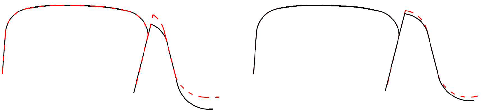
Under the condition that the position of the gauge measuring point remains unchanged, the profile of the switch rail is redesigned. Figure 10 shows a comparison diagram of the reduction of different values for the switch rail of two typical cross-sections.
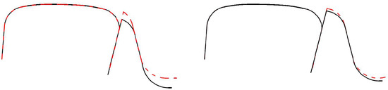
Figure 10.
Reduction of different values for the switch rail with some typical cross-sections.
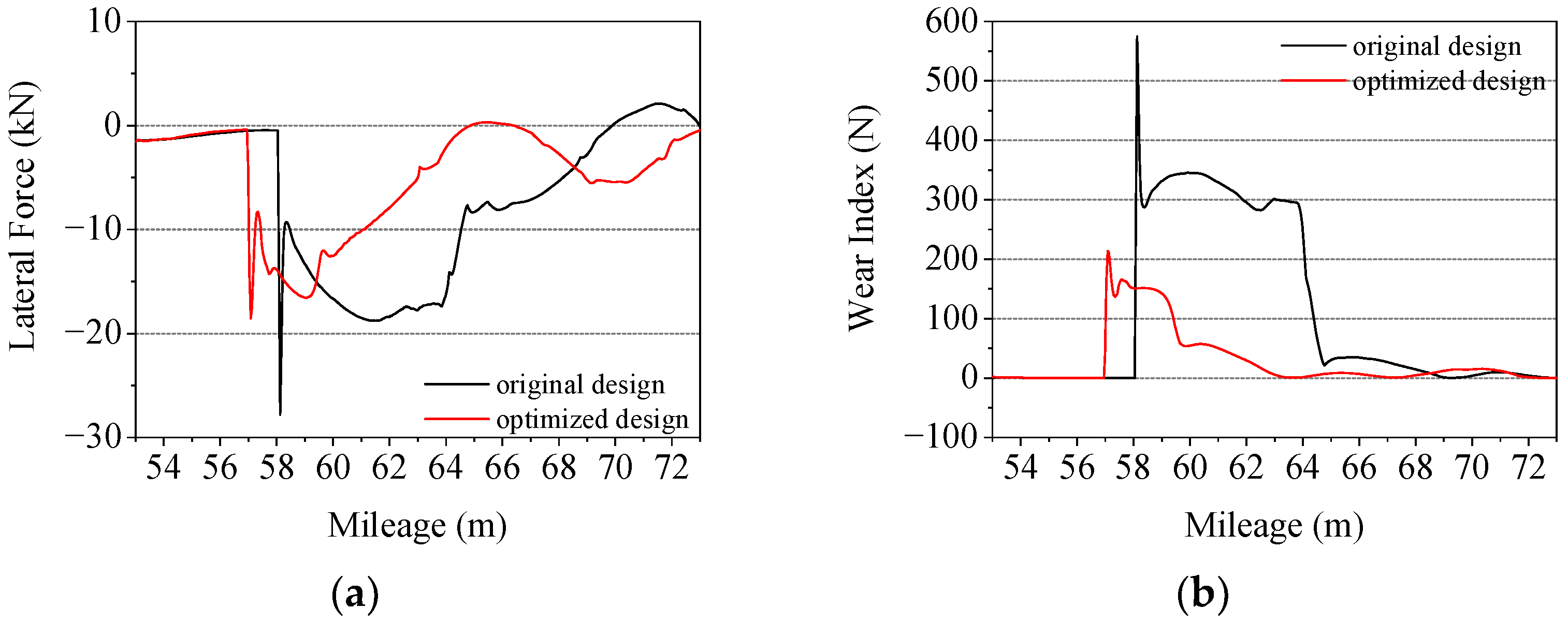
Figure 11 shows the calculation results of the wheel–rail lateral force and wear index of the current and optimized design. It can be seen from the calculation results that the reduced value of switch rail has a significant influence on the wheel–rail lateral impact. Compared with the current design, after adjustment, the wheel–rail lateral force was reduced by 33.2% and the wear index was reduced by 62.8%. With the development of manufacturing technology and material science, and as the switch rail reached sufficient strength, the design of the height reduction of the switch rail is expected to be cancelled to improve the passing safety of a turnout.
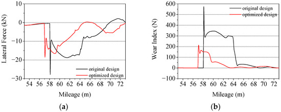
Figure 11.
Wheel–rail lateral force, derailment coefficient, and wear index before and after the adjustment of the height reduction of switch rail. (a) Lateral force; (b) Wear index.
3.4. Other Factors
When the wheel enters the turnout section, it collides with the switch rail and changes its driving direction. Meanwhile, the loss of kinetic energy occurs, which is mainly consumed by physical phenomena such as wheel–rail displacement, elastic deformation, and friction damping caused by wheel–rail impact, which is positively correlated with the impact force. According to the kinetic energy theorem, assuming that the train mass remains unchanged and the elastic deformation of the track is ignored, the change in kinetic energy can be calculated using the following formula:
where is the change of kinetic energy; is the wheel rail impact angle; and and are the mass of the train and the speed before the occurrence of the impact, respectively. As a result,
Hence, the speed of the train entering the turnout and the wheel–rail impact angle are also positively correlated with the lateral wheel–rail impact force of the switch rail.
The curved switch rails are characterized by a complex manufacturing process and large cutting amount at the front tips. Using different cutting modes will result in different plane line types. In this regard, the line types for the curved switch rail are divided into five types: tangent, semi-tangent, secant, semi-secant, and separated semi-tangent types [38]. Reference [39] compares the influence of five cutting modes for the switch blade on the passing performance of the diverging route of a turnout. From the point of view of the calculation results of dynamic indexes such as the derailment coefficient, rate of wheel load reduction, and wheelset lateral force, for 1:42 turnout with a relatively small frog angle, tangent and semi-tangent switch blades are better than the secant, semi-secant, and separated-semi-tangent switch blades; and for 1:18 turnout with a relatively big frog angle, semi-tangent and semi-secant switch blades are better than those with other cutting modes.
4. Conclusions
This paper comprehensively analyzed the influence of design parameters on the wheel–rail lateral impact of the forepart of the curved switch rail. The influencing factors have been summarized. Through the statistics and observation of the calculation results, the following conclusions are obtained.
- (1)
- The decrease in lateral damping of the curved switch rail can effectively attenuate the wheel–rail impact, and then reduce the derailment coefficient in the corresponding section so as to improve the passing safety. The influence of the lateral damping is greater than that of the stiffness. Under different damping conditions, the intensity of the wheel–rail impact has different variation trends with respect to its lateral support stiffness.
- (2)
- The variation in the stiffness and damping may also increase the lateral displacement of the outer rail under wheel–rail impact. However, the displacement is rather small, and it will not cause a gauge variation big enough to have a significant impact on safety [40,41,42].
- (3)
- The change in rail cant has a notable influence on the wheel–rail lateral impact force of the forepart of the curved switch rail. Under the working condition in this paper, the decrease is about 21.3%.
- (4)
- By decreasing the height reduction of the switch rail, the wheel–rail lateral impact can be effectively reduced. On the basis of the calculation results of this paper, the wheel–rail lateral force can be reduced by 33.2%.
- (5)
- The wheel–rail impact angle and the speed of the train are positively correlated with the lateral wheel–rail impact force of the switch rail. Using a reasonable cutting mode for the switch blade will make a positive contribution to reducing the lateral wheel–rail impact force of the switch rail.
Author Contributions
Conceptualization, B.L. and Y.L.; methodology, B.L.; software, B.L.; validation, B.L. and Y.L.; formal analysis, B.L.; investigation, B.L. and Y.L.; resources, Y.L.; writing—original draft preparation, B.L.; writing—review and editing, Y.L.; project administration, Y.L.; funding acquisition, Y.L. All authors have read and agreed to the published version of the manuscript.
Funding
This research was funded by the National Natural Science Foundation of China, grant number 51678446.
Institutional Review Board Statement
Not applicable.
Informed Consent Statement
Not applicable.
Data Availability Statement
Not applicable.
Conflicts of Interest
The authors declare no conflict of interest.
References
- Sadeghi, J.; Masnabadi, A.; Mazraeh, A. Correlations among railway turnout geometry, safety and speeds. Proc. Inst. Civ. Eng. Transp. 2016, 169, 219–229. [Google Scholar] [CrossRef]
- Zhai, W.M.; Wang, K.Y. Safety assessment of trains passing through branch lines of turnouts. J. Tongji Univ. Nat. Sci. 2004, 32, 382–386. [Google Scholar]
- Hiensch, E.J.M.; Burgelman, N. Switch panel wear loading—A parametric study regarding governing train operational factors. Veh. Syst. Dyn. 2017, 55, 1384–1404. [Google Scholar] [CrossRef] [Green Version]
- Lau, A.; Hoff, I. Simulation of train-turnout coupled dynamics using a multibody simulation software. Model. Simul. Eng. 2018, 2018, 8578272. [Google Scholar] [CrossRef] [Green Version]
- Wang, L.; Ping, W.; Zhao, C.; Liu, D.; Ke, W. An experimental study on the characteristics of vibration source in urban rail transit turnouts. Proc. Inst. Mech. Eng. Part F J. Rail Rapid Transit 2020, 234, 945–957. [Google Scholar] [CrossRef]
- de Miguel, A.; Jacobsen, F.; Lau, A.; Santos, I. Uncertainty analysis of track degradation at railway turnouts aided by a multi-body simulation software. J. Braz. Soc. Mech. Sci. Eng. 2019, 41, 544. [Google Scholar] [CrossRef]
- Li, M.; Gao, D.; Li, T.; Luo, S.; Ma, W.; Chen, X.; Tong, L. Dynamic interaction of medium–low-speed maglev train running on the turnout made of steel structures. Veh. Syst. Dyn. 2022, 1–22. [Google Scholar] [CrossRef]
- Wan, C.; Markine, V.; Shevtsov, I. Optimisation of the elastic track properties of turnout crossings. Proc. Inst. Mech. Eng. Part F J. Rail Rapid Transit 2016, 230, 360–373. [Google Scholar] [CrossRef]
- Zhu, J.Y.; Dong, G.Y.; Li, L.; Luo, Y.Y. Comparison investigation on wheel/rail interaction by changing the lateral stiffness of the curved track. J. Railw. Eng. Soc. 2002, 4, 28–32. [Google Scholar]
- Blanco-Saura, A.E.; Velarte-González, J.L.; Ribes-Llario, F.; Real-Herráiz, J.I. Study of the dynamic vehicle-track interaction in a railway turnout. Multibody Syst. Dyn. 2018, 43, 21–36. [Google Scholar] [CrossRef]
- Kisilowski, J.; Kowalik, R. Mechanical wear contact between the wheel and rail on a turnout with variable stiffness. Energies 2021, 14, 7520. [Google Scholar] [CrossRef]
- Grossoni, I.; Hughes, P.; Bezin, Y.; Bevan, A.; Jaiswal, J. Observed failures at railway turnouts: Failure analysis, possible causes and links to current and future research. Eng. Fail. Anal. 2021, 119, 104987. [Google Scholar] [CrossRef]
- Jiang, B.; Ma, M.; Li, M.; Liu, W.; Li, T. Experimental study of the vibration characteristics of the floating slab track in metro turnout zones. Proc. Inst. Mech. Eng. Part F J. Rail Rapid Transit 2019, 233, 1081–1096. [Google Scholar] [CrossRef]
- Chen, X.P.; Wang, P.; Zhang, Y. The reasonable stiffness of ballastless track turnout of 250 km/h passenger dedicated line. J. Railw. Eng. Soc. 2010, 27, 25–28. [Google Scholar]
- Wang, P.; Chen, R.; Xu, J.; Ma, X.; Wang, J. Theories and engineering practices of high-speed railway turnout system: Survey and review. J. Southwest Jiaotong Univ. 2016, 51, 357–372. [Google Scholar]
- Sun, J.; Chi, M.; Jin, X.; Liang, S.; Wang, J.; Li, W. Experimental and numerical study on carbody hunting of electric locomotive induced by low wheel–rail contact conicity. Veh. Syst. Dyn. 2021, 59, 203–223. [Google Scholar] [CrossRef]
- Li, W.; Guan, Q.; Chi, M.; Wen, Z.; Sun, J. An investigation into the influence of wheel–rail contact relationships on the carbody hunting stability of an electric locomotive. Proc. Inst. Mech. Eng. Part F J. Rail Rapid Transit, 2022, in press. [CrossRef]
- Qian, Y.; Wang, P.; Su, Q.; An, B.Y.; Xu, J.M. Effect analysis of rail cant on the wheel-rail contact behavior of high-speed railway. J. Railw. Eng. Soc. 2018, 35, 18–25. [Google Scholar]
- Wang, S.; Qian, Y.U.; Feng, Q.; Luo, X.; Guo, F. Influence of rail cant on high rail side wear on sharp curve of urban transit. In Vehicle-Track Interaction, Proceedings of the 2019 Joint Rail Conference, Snowbird, UT, USA, 9–12 April 2019; ASME: New York, NY, USA, 2019. [Google Scholar]
- Ye, Y.; Sun, Y. Reducing wheel wear from the perspective of rail track layout optimization. Proc. Inst. Mech. Eng. Part K J. Multi-Body Dyn. 2021, 235, 217–234. [Google Scholar] [CrossRef]
- Wang, J.; Chen, X.; Li, X.; Wu, Y. Influence of heavy haul railway curve parameters on rail wear. Eng. Fail. Anal. 2015, 57, 511–520. [Google Scholar] [CrossRef]
- Wu, H.; Kerchof, B. Management of wheel/rail interface to prevent rail rollover derailments. Proc. Inst. Mech. Eng. Part F J. Rail Rapid Transit 2014, 228, 673–686. [Google Scholar] [CrossRef]
- Ghosh, A.; Edwards, J.R.; Dersch, M.S. Effect of design rail cant on concrete crosstie rail seat pressure distribution. In Railroad Infrastructure Engineering, Proceedings of the 2016 Joint Rail Conference, Columbia, SC, USA, 12–15 April 2016; ASME: New York, NY, USA, 2016. [Google Scholar]
- Mojumder, S.; Su, H.; Qiu, C.; Mutton, P.; Singh, A.; Yan, W. The role of bending stress on the initiation of reverse transverse defects. Proc. Inst. Mech. Eng. Part F J. Rail Rapid Transit 2021, 235, 61–72. [Google Scholar] [CrossRef]
- Wang, P.; Gao, L.; Hou, B.-W. Influence of rail cant on wheel-rail contact relationship and dynamic performance in curves for heavy haul railway. Appl. Mech. Mater. 2013, 365–366, 381–387. [Google Scholar] [CrossRef]
- Chang, W.; Cai, X.; Wang, P.; Wang, Q.; Sun, J. Optimizing reduced values of switch rails during the service time of high-speed railway turnouts. J. Transp. Eng. Part A Syst. 2022, 148, 04022031. [Google Scholar] [CrossRef]
- Ma, X.; Wang, P.; Wang, J.; Xu, J. Study on impact of over-limit reduced value of switch rail on dynamic characteristics of switch. J. China Railw. Soc. 2016, 38, 98–105. [Google Scholar]
- Wang, S.; Si, D.; Wang, M.; Ge, J. Influence of value reduced for switch rail of high speed railway on riding quality. China Railw. Sci. 2014, 35, 28–33. [Google Scholar]
- Ding, Z.; Ouyang, B. A Variable-length rational finite element based on the absolute nodal coordinate formulation. Machines 2022, 10, 174. [Google Scholar] [CrossRef]
- Yao, W.; Luo, J.J.; Xie, J.F.; Yuan, J.P. A novel Bezier method for continuous thrust maneuver orbit optimal design. J. Astronaut 2019, 40, 1274–1285. [Google Scholar]
- Zhai, W. Vehicle-Track Coupling Dynamics, 4th ed.; Science Press: Beijing, China, 2015. [Google Scholar]
- Du, L.; Liu, W.; Liu, W.; Ma, L. Study on dynamic characteristics of a curved track in 3 dimensions. China Civ. Eng. J. 2018, 51, 110–120. [Google Scholar]
- Kalker, J.J. Three-Dimensional Elastic Bodies in Rolling Contact; Springer: Dordrecht, The Netherlands, 1990. [Google Scholar]
- Kalker, J.J. A fast algorithm for the simplified theory of rolling contact. Veh. Syst. Dyn. 1982, 11, 1–13. [Google Scholar] [CrossRef]
- Huang, Y.; Wang, J.; Le, W.; Zhang, L.; Su, J. Study on mechanical behaviours of rail fasteners and effects on seismic performance of urban rail viaduct. Structures 2021, 33, 3822–3834. [Google Scholar] [CrossRef]
- Yang, G.; Zhao, F.; Li, Q.; Liang, Y.; Lin, G. Study of Influences of high-speed train wheel-rail contact geometric parameters on wheel-rail wear. J. China Railw. Soc. 2019, 41, 50–56. [Google Scholar]
- Wang, P.; Guo, Q.; Chen, J.; Yu, H.; Xu, J. Research on the effect of wheel-rail lubrication on curved switch rail wear in high-speed turnout. J. Railw. Eng. Soc. 2019, 36, 17–22. [Google Scholar]
- Wang, P. Chapter 2—Layout Design. In Design of High-Speed Railway Turnouts; Elsevier: Amsterdam, The Netherlands, 2015; pp. 37–75. [Google Scholar]
- Cao, Y.; Wang, P.; Deng, T. Analysis on cutting mode selection for switch blade based on wheel-rail system dynamics. J. China Railw. Soc. 2014, 36, 73–79. [Google Scholar]
- Hasan, N. Alignment tolerance of rail tracks. In Proceedings of the ASCE International Conference on Transportation and Development, Seattle, WA, USA, 26–29 May 2020; ASCE: Reston, VA, USA, 2020; pp. 114–124. [Google Scholar]
- de O Lima, A.; Edwards, J.R.; Chavez Quiroz, L.W.; Qian, Y.; Dersch, M.S. Load and response quantification of direct fixation fastening systems for heavy rail transit infrastructure. Proc. Inst. Mech. Eng. Part F J. Rail Rapid Transit 2021, 235, 1110–1121. [Google Scholar] [CrossRef]
- Fujimoto, H.; Tanifuji, K.; Miyamoto, M. Influence of track gauge variation on rail vehicle dynamics (an examination based on comparison between data from a test train running on track with irregularity artificially set and numerical simulation). Proc. Inst. Mech. Eng. Part F J. Rail Rapid Transit 2000, 214, 223–230. [Google Scholar] [CrossRef]


Publisher’s Note: MDPI stays neutral with regard to jurisdictional claims in published maps and institutional affiliations. |
© 2022 by the authors. Licensee MDPI, Basel, Switzerland. This article is an open access article distributed under the terms and conditions of the Creative Commons Attribution (CC BY) license (https://creativecommons.org/licenses/by/4.0/).