Article

Nonlinear Control of a Hydraulic Exoskeleton 1-DOF Joint Based on a Hardware-In-The-Loop Simulation

School of Automation Science and Electrical Engineering, Beihang University, Beijing 100191, China
*
Author to whom correspondence should be addressed.
Machines 2022, 10(8), 607; https://doi.org/10.3390/machines10080607
Submission received: 16 June 2022 / Revised: 16 July 2022 / Accepted: 20 July 2022 / Published: 25 July 2022
(This article belongs to the Section Machine Design and Theory)

Abstract

:
Aiming at the difficulty of debugging the exoskeleton control system driven by a hydraulic cylinder, a research method of a nonlinear control strategy for the hydraulic exoskeleton system with 1 degree of freedom (DOF) joint is proposed. Based on a hardware-in-the-loop (HIL) simulation, this method establishes the dynamic model of the 1-DOF joint system of the hydraulic driven exoskeleton, constructs the HIL simulation test platform based on the Linux real-time kernel patch, and studies the nonlinear control strategy of the 1-DOF joint system on this platform system. The control effects of the PID control algorithm and the backstepping method on nonlinear control are compared, and the controller parameters are tested on the HIL simulation platform. From the experimental results of the HIL simulation, the research method has the advantages of low cost, high efficiency of system development, safety, and reliability. It has important reference value for the development and debugging of a hydraulic exoskeleton control system.

1. Introduction

In recent years, a wearable robot that can improve human capacity in heavy load carrying applications has attracted great interest from researchers. The lower limb exoskeleton system is a representative of this kind of robot. It possesses a better adaptability to complex terrain such as stairs and slopes than wheeled machinery.
The actuator is the key component of an exoskeleton system which can complete most actions. Common actuators of the exoskeleton system include the motor, pneumatic artificial muscle and hydraulic servo cylinder. Different actuators used in an exoskeleton system will have different requirements for its control strategy. In the past few years, many kinds of exoskeletons have been developed and evaluated for research purposes.
The electric motor is the most commonly used as the exoskeleton actuator. Zhu [1] introduced a lower limb exoskeleton, which can realize the complementarity and interaction between human intelligence and robot mechanical strength. Wang [2] proposed a control method that can provide gait assistance in the lateral and sagittal planes. Brahmi [3,4,5,6,7] described the application of a relatively new control technique called virtual decomposition control (VDC) to a 7-DOF exoskeleton robot arm.
The exoskeleton system driven by pneumatic artificial muscle is lighter than that driven by an electric motor. Tscheersky [8] showed a pneumatic bending actuator for an upper limb-assisted wearable robot that uses thin McKibben muscles and bending strips. Xie [9] proposed a new type of flexible exoskeleton with variable stiffness based on wire driving and clamping. Di [10] presented a bionic design of a soft and modular lower limb-assisted exoskeleton based on pneumatic quasi passive actuation. The method proposed by Henderson [11] involves a combined dynamic model of a lower body musculoskeletal system and pneumatic actuator dynamics. The disadvantage of a pneumatic manual muscle actuator is that the output force is relatively small.
Due to the high power to weight ratio, hydraulic actuators are widely used in the development of such exoskeleton systems that need small sizes and provide a large force at the same time. Zhang [12] proposed an adaptive cascade control scheme based on hierarchical Lyapunov for the lower limb exoskeleton with control saturation. Liu [13] promoted an adaptive backstepping sliding mode control (BSMC) scheme to resolve the nonlinear problem of the system dynamics. Chen [14] addressed the dynamics and interactive force control of a 1-DOF articular exoskeleton and proposed a backstepping control method based on full dynamics in order to overcome the bandwidth restriction of common cascade control. GLOWINSKI [15] aimed to use inertial measurement devices to detect the angle of lower limb joints during walking and running. Yang [16,17,18] presented a new control scheme for the trajectory tracking of an electro-hydraulic valve-controlled actuator in lower limb load exoskeleton. GLOWINSKI [19] described a mathematical model of a hydraulic lower limb exoskeleton. Chen [20] promoted an adaptive robust cascade force controller for 3-DOF hydraulic leg exoskeleton to achieve the accurate tracking of human motion.
The study of nonlinear control is very important to obtain better control effects because the hydraulic driven lower limb exoskeleton system has a strong nonlinearity. In order to save operating space, a single piston rod hydraulic cylinder is usually used as the actuator to the hydraulic-driven exoskeleton system. Special attention should be paid to the design of the control algorithm due to the nonlinear characteristics of the forward and reverse motion of a single piston rod hydraulic cylinder. Liu [21] proposed a dually extended state observer (ESO) with full state to estimate matched and unmatched disturbances and designed a robust controller to compensate for unmatched disturbances. Guo [22] presented a nonlinear backstepping control method based on high gain observer suitable for single rod electro-hydraulic actuator, which is not a strict feedback nonlinear system. Tian [23] proposed a sliding mode control method to track the desired position of the electro-hydraulic single rod actuator of the projectile transfer arm.
One of the commonly used nonlinear control algorithms is the backstepping method. Wang [24] proposed an adaptive backstepping controller (ABC) for a lower limb exoskeleton driven by a DC motor. However, the above control algorithm is not combined with mechanical system dynamics. Khamar [25] proposed a nonlinear disturbance observer (NDO) to reduce the influence of uncertainty and external disturbances in the whole system modelling. Sun [26] proposed a new model-free fractional-order adaptive backstepping control scheme with the function of restraining joint angle tracking errors for a wearable exoskeleton. Yang [18] proposed a model-free backstepping sliding mode control strategy for a wearable exoskeleton through a second-order ultra-local model and time delay estimation technique. Chen [27] introduced a humanoid prototype of a lower limb exoskeleton with 2 DOF to evaluate the comfortable wearing effect between a human and the exoskeleton. Zhang [13] proposed an adaptive cascade control scheme based on hierarchical Lyapunov for the lower limb exoskeleton with control saturation.
The hydraulic servo driven exoskeleton system has the characteristics of strong nonlinearity, which will lead to the problem of difficult debugging for its control algorithm. The HIL simulation is a system-level testing technique for embedded systems in a comprehensive, cost-effective and repeatable way so that its application can solve the above problems. Zaev [28] introduced a program of developing a HIL simulator for servo valve-driven systems and MISMO hydraulic systems. Yong [29] proposed a new type of electric booster (E-booster), which exhibited superior performance advantages over the traditional vacuum boosters. Lim [30] proposed the basic concept of HIL simulation and AMESim model of hydraulic components. Karpenko [31] introduced a design method of a robust force control system for an electro-hydraulic load emulator utilized as a part of a HIL flight simulation experiment. Chen [32] proposed a new pressure-difference-limiting control method for hydraulic pressure modulation based on the on-off solenoid valve and carried out the HIL simulation test on the algorithm under typical braking procedures. The research contents of the above literature did not realize the joint simulation of a mechanical system and a hydraulic system.
The purpose of this paper was to replace the hydraulic and mechanical parts and sensors of the hydraulic servo-driven exoskeleton system with a simulation model. This method not only solves the problems of deriving the dynamic equations without combining mechanical system with hydraulic system, but also solves the difficulty of debugging the control algorithm of the electro-mechanical–hydraulic system. Combined with the Newton Euler equations of a mechanical system and the dynamic equations of a valve-controlled single piston rod hydraulic servo system, this paper derives the overall dynamic equations of a valve-controlled hydraulic servo system with a 1-DOF joint and develops a HIL simulation system based on Linux real-time kernel patch, which makes the debugging of the control algorithm more convenient.

2. HIL Platform of Hydraulic Exoskeleton

2.1. Mechanical Structure of the Exoskeleton System

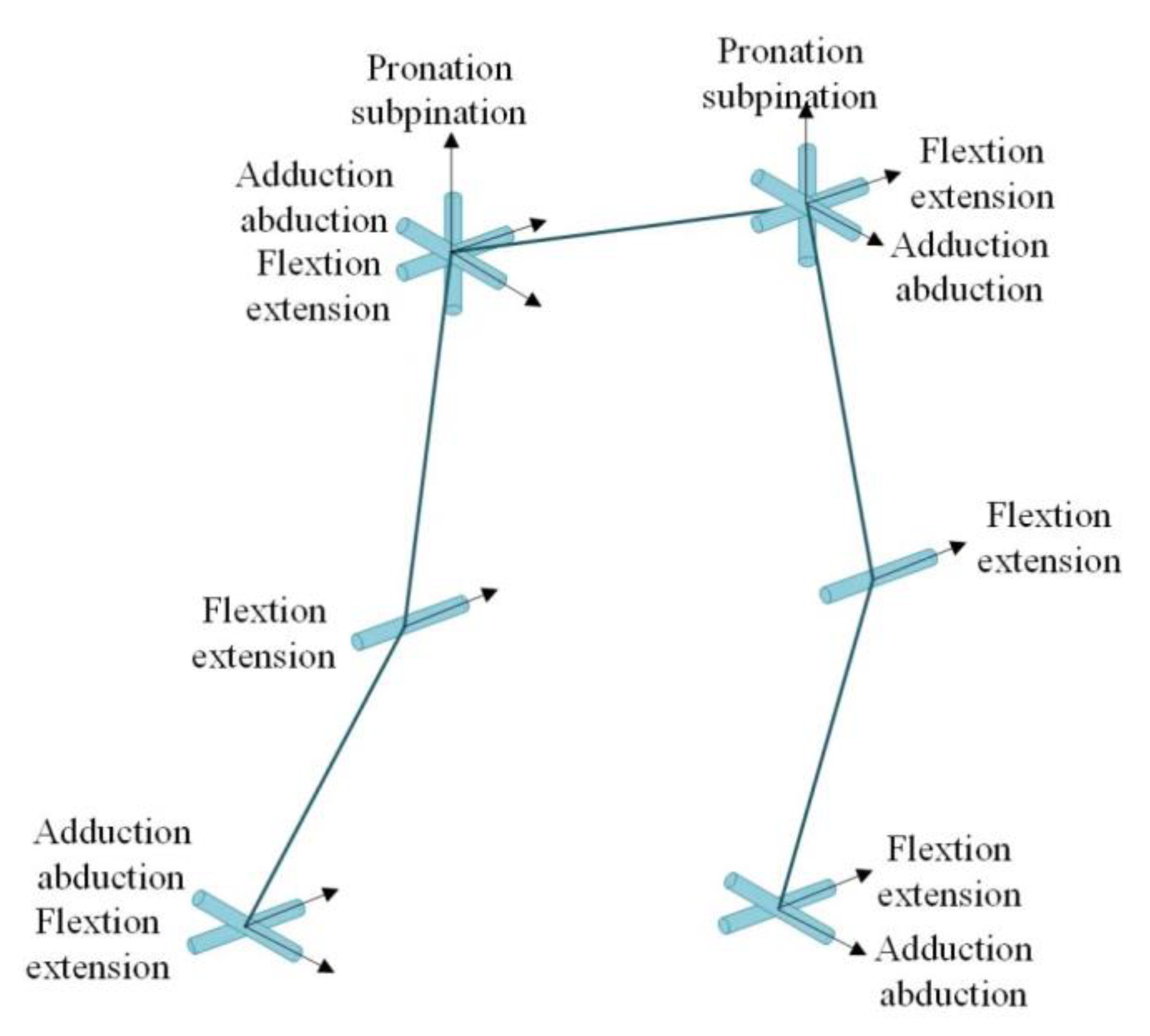
The mechanical structure of the exoskeleton developed is shown in Figure 1. The joints of the exoskeleton are designed with simplified joints according to the human body structure, as shown in Figure 2.
Each hip joint consists of three rotation DOF, each knee joint consists of one rotation DOF and each ankle joint consists of two rotation DOF. The flexion\extension DOF in the sagittal plane is designed to enable the wearer to walk forward, in which the DOF of the knee and hip is actively controlled by the hydraulic cylinders, the DOF of the ankle is passively controlled by a spring steel sheet, and the rest of the DOFs are free.

2.2. Joint Dynamic Modelling

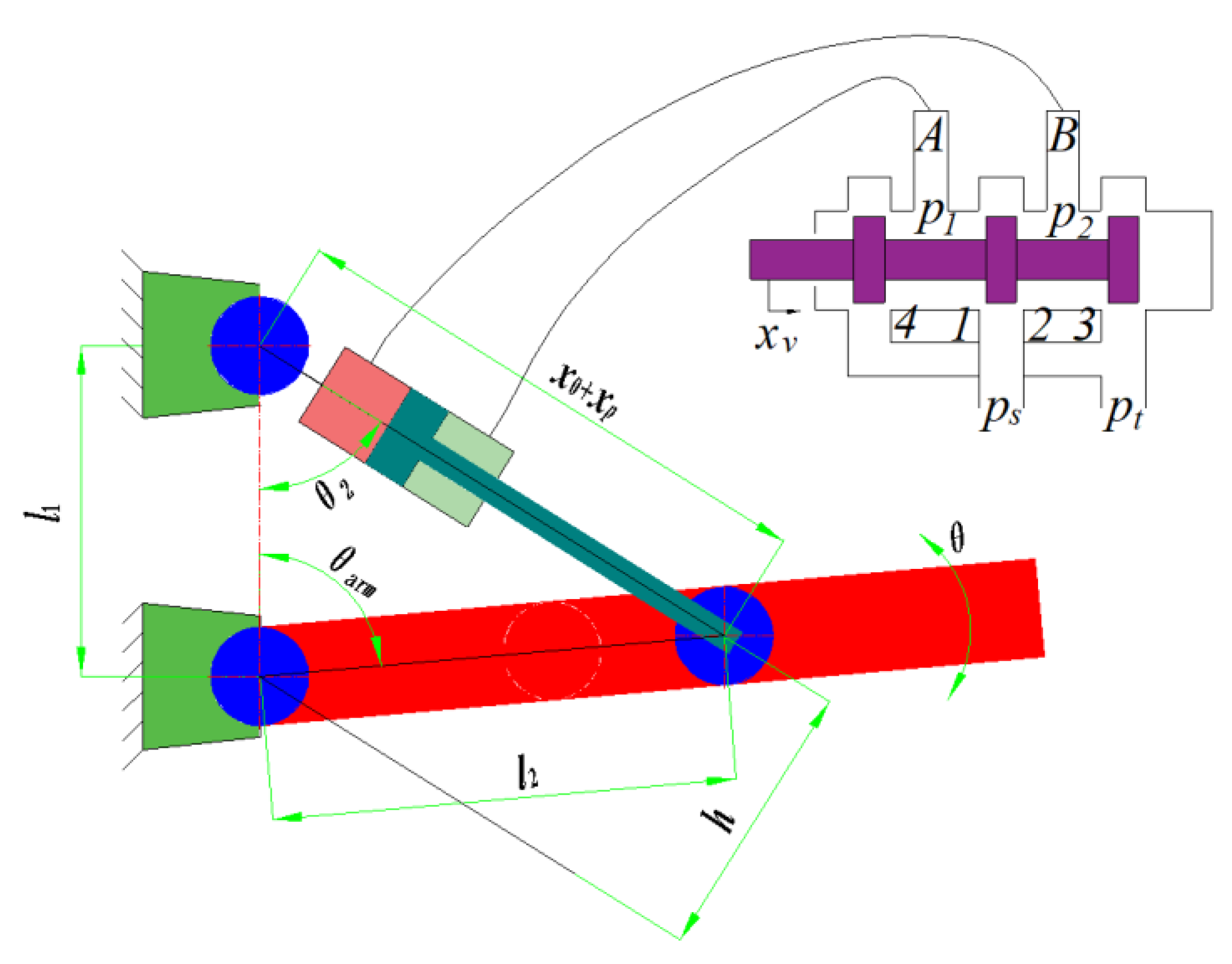
For easy illustration, only one joint is considered below, and all other joints can be considered similarly. Taking the hip joint as an example, the schematic diagram of the 1-DOF joint system is shown in Figure 3.
The 1-DOF joint system consists of a mechanical system and an electro-hydraulic servo system. The mechanical system is composed of a fixed base and a swinging mechanical arm, and the electro-hydraulic servo system contains a hydraulic cylinder and a servo valve. Deriving the dynamic model of the mechanical-electro-hydraulic system is the fundamental work of the controller design.

2.2.1. Dynamic Model of the Electro-Hydraulic Servo System

As shown in Figure 3, the rotary motion of the arm is performed by the hydraulic cylinder controlled by the servo valve. According to Newton’s second law, the force balance equation of the cylinder piston rod can be described as
m x ¨ p = p 1 A 1 p 2 A 2 F L F f
where m is the mass of the system, x p is the displacement of the piston, p 1 and p 2 are the pressures in each chamber of the cylinder, A 1 and A 2 are the areas of the piston and rob chamber, B is the viscous friction coefficient, F L is the external load force generated by the arm’s motion, and F f is coulomb plus viscous friction.
According to [33], the flow continuity equation of rod and piston chambers are
{ V 1 ( x p ) β e p ˙ 1 = A 1 x ˙ p + Q 1 c l i ( p 1 p 2 ) V 2 ( x p ) β e p ˙ 2 = A 2 x ˙ p Q 2 + c l i ( p 1 p 2 )
where V 1 and V 2 are the total control volumes of two chambers, Q 1 and Q 2 are the flows into the forward and return chambers, β e is the effective bulk modulus, and c l i is the internal leakage coefficient.
Note that
{ V 1 = V h 1 + A 1 x p V 2 = V h 2 A 2 x p
where V h 1 and V h 2 are the chamber volumes when x p = 0 .
Since Q 1 and Q 2 are related to the spool valve displacement of the servo valve [34], then
{ Q 1 = k q x v Δ p 1 ,   Δ p 1 = { p s p 1 x v > 0 p 1 p t x v 0 Q 2 = k q x v Δ p 2 ,   Δ p 2 = { p 2 p t x v > 0 p s p 2 x v 0
where k q 1 and k q 2 are the flow gain coefficients of the servo valve, k q = C d w 2 / ρ , ( C d is the orifice discharge coefficient, w is the spool valve area gradient; ρ is the density of hydraulic oil), x v is the displacement of servo valve spool; p t is the return pressure, p s is the supply pressure.
The relationship between the input signal of the servo valve and the spool displacement is considered a second-order oscillation segment. Therefore, the dynamic equation of the servo valve can be described as
x ¨ v = 2 ζ v ω v x ˙ v ω v 2 x v + k v u
where ω v is the inherent frequency of the servo valve, ζ v is the damping ratio of the servo valve, k v is the proportional gain of the servo valve, and u is the control input electric current.
Setting the scale coefficient α = A 2 / A 1 , and defining
p L = F L / A 1 = ( A 1 p 1 A 2 p 2 ) / A 1 = p 1 α p 2
At the steady state of the hydraulic cylinder, according to the force balance Equation (1) and the flow continuity Equation (2):
p 1 A 1 p 2 A 2 = F L
Q 1 A 1 = Q 2 A 2
Defining the load flow as
Q L = Q 1 + α Q 2 1 + α 2
When x ˙ p > 0 , x v > 0 , from Equation (3)
Q 1 Q 2 = p s p 1 p 2 = A 1 v A 2 v = 1 α
Then obtaining
p s = p 1 + 1 α 2 p 2
Combining Equation (6):
p 1 = p L + α 3 p s 1 + α 3
p 2 = α 2 ( p s p L ) 1 + α 3
Q L = k q x v p s p L 1 + α 3
According to Equation (2)
Q L = A 1 x ˙ p + V 0 β e ( 1 + α 2 ) p ˙ L + A 1 ( 1 α 3 ) β e ( 1 + α 2 ) ( 1 + α 3 ) p ˙ L x p + c l i ( 1 + α ) 1 + α 3 p L + c l i α 2 ( α 2 1 ) ( 1 + α 2 ) ( 1 + α 3 ) p s
Usually, A 1 x p V h 1 , α A 1 x p V h 2 , then the term containing x p in the above equation can be ignored, and the final practical expression is simplified as
Q L = A 1 x ˙ p + V 0 β e ( 1 + α 2 ) p ˙ L + c l i ( 1 + α ) 1 + α 3 p L + c l i α 2 ( α 2 1 ) ( 1 + α 2 ) ( 1 + α 3 ) p s
When x ˙ p < 0 , x v < 0 , according to Equation (4)
Q 1 Q 2 = p 1 p s p 2 = A 1 v A 2 v = 1 α
Then
p s = α 2 p 1 + p 2
Combining Equation (11)
p 1 = α p s + p L 1 + α 3
p 2 = p s α 2 p L 1 + α 3
Q L = k q x v α p s + p L 1 + α 3
Then obtaining
Q L = A 1 x ˙ p + V 0 β e ( 1 + α 2 ) p ˙ L + c l i ( 1 + α ) 1 + α 3 p L + c l i ( α 2 1 ) ( 1 + α 2 ) ( 1 + α 3 ) p s

2.2.2. Dynamic Model of the Mechanical System

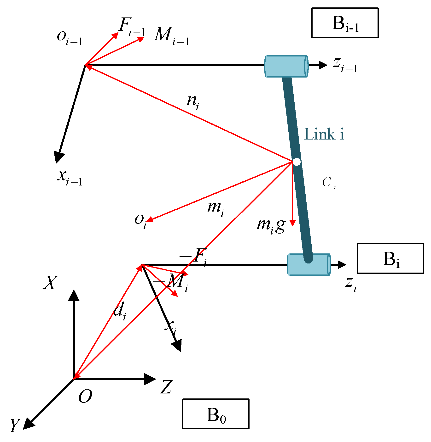
This section addresses the dynamic modelling of the 1 DOF pendulum joint system proposed above. The theory of the dynamic modelling of the mechanical system is based on the Newton–Euler equation. The link (i) and its vectorial kinematic characteristics are shown in Figure 4.
According to [35], the Newton–Euler equations of motion for link (i) in the global coordinate frame are
F 0 i 1 F 0 i + F 0 e i = m i α 0 i
M 0 i 1 M 0 i + M 0 e i + ( d 0 i 1 r 0 i ) × F 0 i 1 ( d 0 i r 0 i ) × F 0 i = I 0 i α 0 i
where F 0 i 1 , F 0 i are the driving and driven force of link (i), F 0 e i are the external forces acting on link (i), m i is the mass of link (i), a 0 i is the linear acceleration of link (i), M 0 i 1 , M 0 i are the driving and driven moment acting on the link (i); M 0 e i are the external moments acting on the link (i); r 0 i is the global position of the mass center of link (i), d 0 i 1 , d 0 i are the global positions of the origin of body frames B i and B i 1 , respectively, I 0 i is the rotational inertia around the mass center of link (i), α 0 i is the angular acceleration of link (i).
The relative position vectors of the one-link manipulator are
d 0 i 1 r 0 i = [ l cos θ / 2 l sin θ / 2 0 ] , d 0 i r 0 i = [ l cos θ / 2 l sin θ / 2 0 ]
where l is the length of the link and θ is the rotary joint included angle with the Z axis.
The torque acting on the joint can be derived using the following equations:
r 0 1 = n 0 1 ω 0 1 = θ ˙ k α 0 1 = ω ˙ 0 1 = θ ¨ k g = g j a 0 C = α 0 1 × r 0 1 ω 0 1 × ( ω 0 1 × r 0 1 ) = [ l θ ¨ sin θ / 2 + l θ ˙ 2 ( cos θ ) / 2 l θ ¨ cos θ / 2 + l θ ˙ 2 ( cos θ ) / 2 0 ]
R Z , θ = [ cos θ sin θ 0 sin θ cos θ 0 0 0 1 ]
I 0 1 = R Z , θ I 1 1 R Z , θ T = R Z , θ [ I x 0 0 0 I y 0 0 0 I z ] R Z , θ T = [ I x cos 2 θ + I y sin 2 θ ( I x I y ) cos θ sin θ 0 ( I x I y ) cos θ sin θ I y cos 2 θ + I x sin 2 θ 0 0 0 I z ]
[ τ X τ Y τ Z ] = [ 0 0 ( I z + m 1 l 2 4 ) θ ¨ + 1 2 m 1 g l cos θ ]
where I z is the rotational inertia with Z axis, g is the gravitational acceleration.
Therefore, the torque acting on the Z axis is
τ z = ( I z + m l 2 4 ) θ ¨ + 1 2 m g l cos θ + τ f
where τ f is the coulomb plus viscous friction torque.
Referring to the Figure 3, set the origin angle between the arm and the Z axis to 90°, then
θ a r m = 90 ° θ
Applying the trigonometric cosine theorem in Figure 3, the functional relationship between the displacement of the hydraulic cylinder x p and the swing angle of the robot arm θ can be expressed as
θ = 90 ° arccos l 1 2 + l 2 2 ( x 0 + x p ) 2 2 l 1 l 2
and
θ 2 = arccos [ l 1 2 + ( x 0 + x p ) 2 l 2 2 2 l 1 ( x 0 + x p ) ]
The length of the force arm d can be derived from (34)
h = l 1 sin ( θ 2 )
Ignoring the dynamic characteristics of the hydraulic cylinder, the torque generated by the hydraulic cylinder is calculated by the following formula:
τ Z = h F L = h ( A 1 p 1 A 2 p 2 )

2.2.3. Overall System Dynamic Equation

Combining the above derivation process, the dynamic characteristic equation of the system can be described as
{ h A 1 p L = ( I Z + m 1 l 1 2 4 ) θ ¨ + 1 2 m 1 g l 1 cos θ + τ f p ˙ L = { A 1 β e ( 1 + α 2 ) V 0 x ˙ p + k q β e ( 1 + α 2 ) V 0 p s p L 1 + α 3 x v , x v > 0 A 1 β e ( 1 + α 2 ) V 0 x ˙ p + k q β e ( 1 + α 2 ) V 0 α p s + p L 1 + α 3 x v , x v 0 x ¨ v = 2 ζ v ω v x ˙ v ω v 2 x v + k v ω v 2 u
Defining the system states as
x = [ x 1 , x 2 , x 3 , x 4 , x 5 ] = [ θ , θ ˙ , p L , x v , x ˙ v ]
{ x ˙ 1 = x 2 x ˙ 2 = φ 2 f 2 ( x 1 ) + g 2 ( h ) x 3 x ˙ 3 = { φ 3 f 3 ( x ˙ p ) + ϕ 3 g 3 ( x 3 ) x 4 , x 4 > 0 φ 3 f 3 ( x ˙ p ) + ϕ 3 g 3 ( x 3 ) x 4 , x 4 0 x ˙ 4 = x 5 x ˙ 5 = f 5 ( x 4 , x 5 ) + ϕ 5 u
where
φ 2 = 1 ( I Z + m 1 l 1 2 4 ) g 2 ( h ) = A 1 ( I Z + m 1 l 1 2 4 ) h φ 3 = A 1 β e ( 1 + α 2 ) V 0 ϕ 3 = k q β e ( 1 + α 2 ) V 0 f 2 ( x 1 , x 2 ) = 1 2 m 1 g l 1 cos x 1 + τ f τ f = F N [ μ v tanh ( k x 2 ) + μ c x 2 ] f 3 ( x ˙ p ) = x ˙ p g 3 ( x 3 ) = p s x 3 1 + α 3 g 3 ( x 3 ) = α p s + x 3 1 + α 3 f 5 ( x 4 , x 5 ) = 2 ζ v ω v x 5 + ω v 2 x 4 , ϕ 5 = k v ω v 2
where τ f is the coulomb plus viscous friction torque, F N is the normal force, μ v is the viscous friction coefficient, μ c is the coulomb friction coefficient, and k is the steepness of the coulomb friction curve [36].

2.3. Nonlinear Control Strategies

To find the correct angle command of the mechanical-electro-hydraulic system, a backstepping controller was developed for the state space in (39). The procedure of designing the controller is presented in this section as follows.
Step 1: The system angle tracking error is defined as
e 1 = x 1 x 1 , d
Then, the time derivative term of tracking error is calculated as
e ˙ 1 = x ˙ 1 x ˙ 1 , d = x 2 x ˙ 1 , d
The Lyapunov function and its derivative are defined as
V 1 = 1 2 e 1 2 V ˙ 1 = e 1 e ˙ 1 = e 1 ( x 2 x ˙ 1 , d )
The virtual control signal of the system above is defined as
x 2 = x 2 , d = k 1 e 1 + x ˙ 1 , d
Then
V ˙ 1 = e 1 e ˙ 1 = e 1 ( x 2 x ˙ 1 , d ) = k 1 e 1 2 < 0
Step 2: The system angle velocity tracking error is defined as
e 2 = x 2 x 2 , d
Taking the time derivative of the above equation:
e ˙ 2 = x ˙ 2 x ˙ 2 , d = φ 2 f 2 ( x 1 ) + ϕ 2 x 3 x ˙ 2 , d
Consider a Lyapunov function and its derivative function:
V 2 = V 1 + 1 2 e 2 2 V ˙ 2 = V ˙ 1 + e 2 e ˙ 2 = V ˙ 1 + e 2 [ φ 2 f 2 ( x 1 ) + g 2 ( h ) x 3 x ˙ 2 , d ]
The virtual control signal of the 2nd step is defined as
x 3 = x 3 , d = k 2 e 2 + x ˙ 2 , d + φ 2 f 2 ( x 1 ) g 2 ( h )
Then
V ˙ 2 = V ˙ 1 + e 2 e ˙ 2 = k 1 e 1 2 k 2 e 2 2 < 0
Step 3: The system load pressure tracking error and its derivative are defined as
e 3 = x 3 x 3 , d e ˙ 3 = x ˙ 3 x ˙ 3 , d = φ 3 f 3 ( x ˙ p ) + ϕ 3 g 3 ( x 3 ) x 4 x ˙ 3 , d
Consider a Lyapunov function and its derivative function:
V 3 = V 2 + 1 2 e 3 2 V ˙ 3 = V ˙ 2 + e 3 e ˙ 3 = V ˙ 2 + e 3 [ φ 3 f 3 ( x ˙ p ) + ϕ 3 g 3 ( x 3 ) x 4 x ˙ 3 , d ]
If we define
x 4 = x 4 , d = k 3 e 3 + x ˙ 3 , d + φ 3 f 3 ( x ˙ p ) ϕ 3 g 3 ( x 3 )
Then
V ˙ 3 = V ˙ 2 + e 3 e ˙ 3 = k 1 e 1 2 k 2 e 2 2 k 3 e 3 2 < 0
Step 4: The system valve displacement tracking error and its derivative are defined as
e 4 = x 4 x 4 , d e ˙ 4 = x ˙ 4 x ˙ 4 , d = x 5 x ˙ 4 , d
Consider a Lyapunov function and its derivative function:
V 4 = V 3 + 1 2 e 4 2 V ˙ 4 = V ˙ 3 + e 4 e ˙ 4 = V ˙ 3 + e 4 [ x 5 x ˙ 4 , d ]
If we define
x 5 = x 5 d = k 4 e 4 + x ˙ 4 , d
Then
V ˙ 4 = V ˙ 3 + e 4 e ˙ 4 = k 1 e 1 2 k 2 e 2 2 k 3 e 3 2 k 4 e 4 2 < 0
Step 5: The system valve velocity tracking error and its derivative are defined as
e 5 = x 5 x 5 , d e ˙ 5 = x ˙ 5 x ˙ 5 , d = f 5 ( x 4 , x 5 ) + ϕ 5 u x ˙ 5 , d
Consider a Lyapunov function and its derivative function:
V 5 = V 4 + 1 2 e 5 2 V ˙ 5 = V ˙ 4 + e 5 e ˙ 5 = V ˙ 4 + e 5 [ f 5 ( x 4 , x 5 ) + ϕ 5 u x ˙ 5 , d ]
If we define
u = k 5 e 5 + x ˙ 5 , d + f 5 ( x 4 , x 5 ) ϕ 5
Then
V ˙ 5 = V ˙ 4 + e 5 e ˙ 5 = k 1 e 1 2 k 2 e 2 2 k 3 e 3 2 k 4 e 4 2 k 5 e 5 2 < 0
System stability is guaranteed.

2.4. Development of the HIL Platform

From the above theoretical analyses, it can be seen that the dynamic equations and nonlinear control algorithms of the 1-DOF joint of the exoskeleton system are complex. There are certain risks if the development and debugging of the control algorithm are carried out directly on the physical exoskeleton system. For example, if there is an error in the control algorithm, mechanical system misoperation and stroke overrun may occur, which will lead to mechanical structure damage and even personal injury. In addition, the nonlinear control algorithm developed in this paper requires an accurate mastery of the key parameters of the controlled system, such as the damping ratio, in order to obtain good control effects. However, for the physical control system, it is usually tedious to obtain these key parameters through testing. The above two problems can be solved by introducing the HIL simulation system in the process of system development and debugging. Replacing the controlled object entity with the HIL simulation system can avoid dangerous situations. At the same time, the key parameters of the mathematical model can be arbitrarily set to simulate any working state, even the state that is difficult to reproduce in reality. Therefore, the development of control algorithms for exoskeleton systems with the help of HIL simulation technology is a better solution.
Simulation is classified according to the model used: mathematical simulation and HIL simulation. For an electro-mechanical–hydraulic control system, mathematical simulation is used to describe the controlled object and control algorithm by a mathematical model. The disadvantage is that the control algorithm needs to be ported to the physical controller again when the simulation is completed. However, in a HIL simulation, the side of the controlled object or the control algorithm is assumed by the physical object. If the controlled object is a physical object, it is generally called a rapid prototype simulation and if the controller and control algorithm are physical objects, it is called a HIL simulation. The purpose of using a HIL simulation in this paper was to facilitate the debugging of the control algorithm while the dynamic model of the system was derived. Therefore, the HIL simulation system was selected as the experimental platform to develop a successful control algorithm, which can be directly transplanted to the physical exoskeleton system for attitude control, to improve the development efficiency, and to avoid dangerous situations.

2.4.1. Overall System Architecture

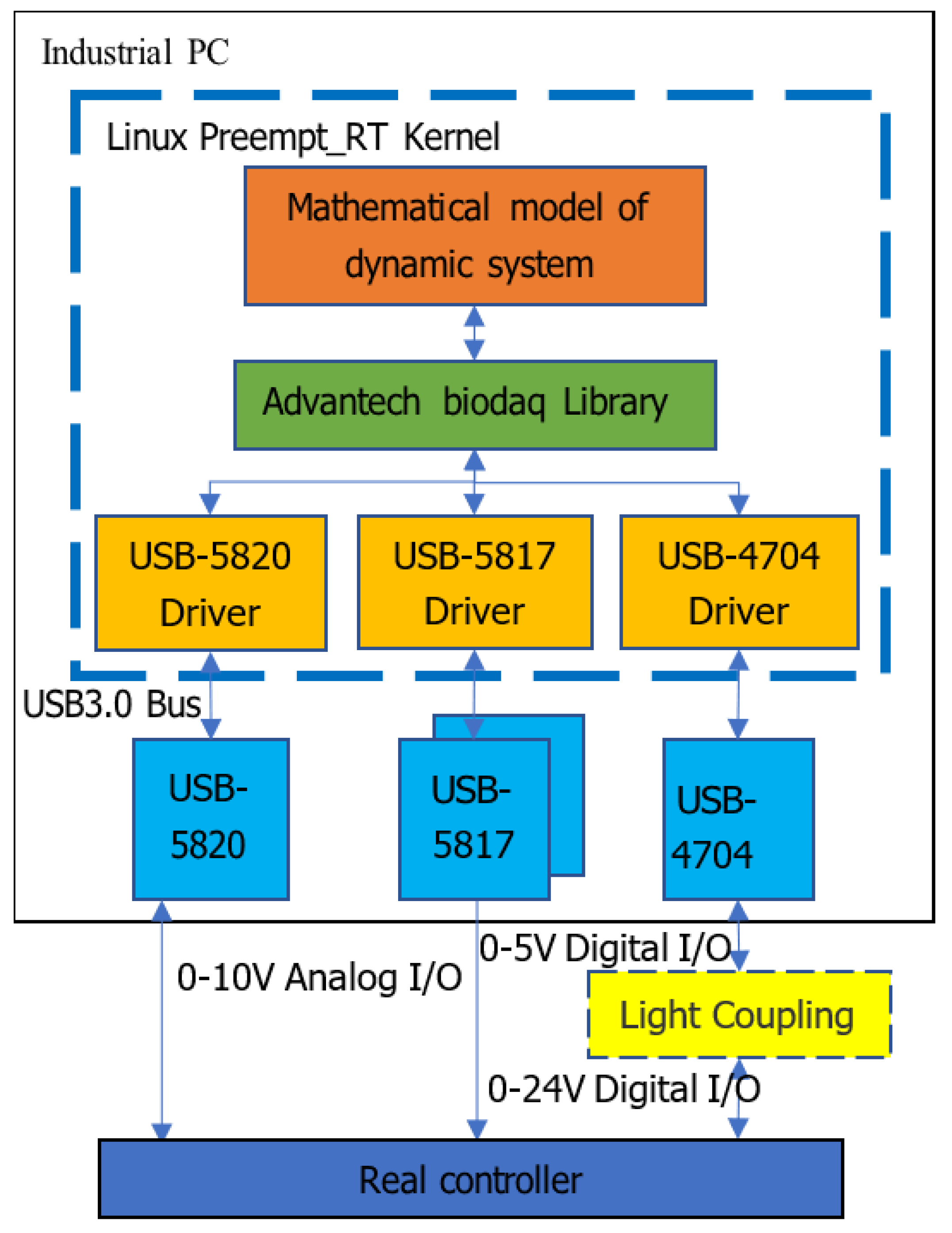
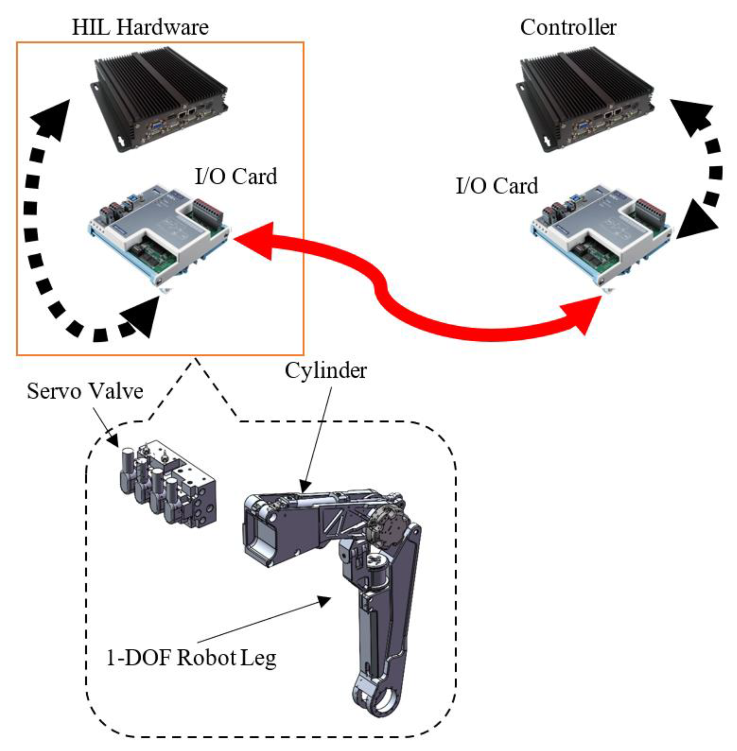
Since the common HIL simulation platforms are expensive, this paper adopted the method of the independent development on the HIL simulation platform to debug the control algorithms. The HIL simulation platform developed in this paper was divided into a hardware part and a software part. The hardware part consists of the simulator interface and the controller. The simulator interface is used to output the dynamic system state variables calculated by the software to simulate the sensor part of the physical system and the physical controller is used as the carrier of the control algorithm operation. The software part is divided into the dynamic solution part and the nonlinear control algorithm part. The dynamic solution part uses the Runge Kutta method to solve the differential equations in real-time to simulate the operation of the physical system. The nonlinear control algorithm part reads the state variables of the dynamic solver part under the action of a real-time timer and performs nonlinear control. The structure schematic of the HIL simulation system is shown in Figure 5.

2.4.2. Hardware

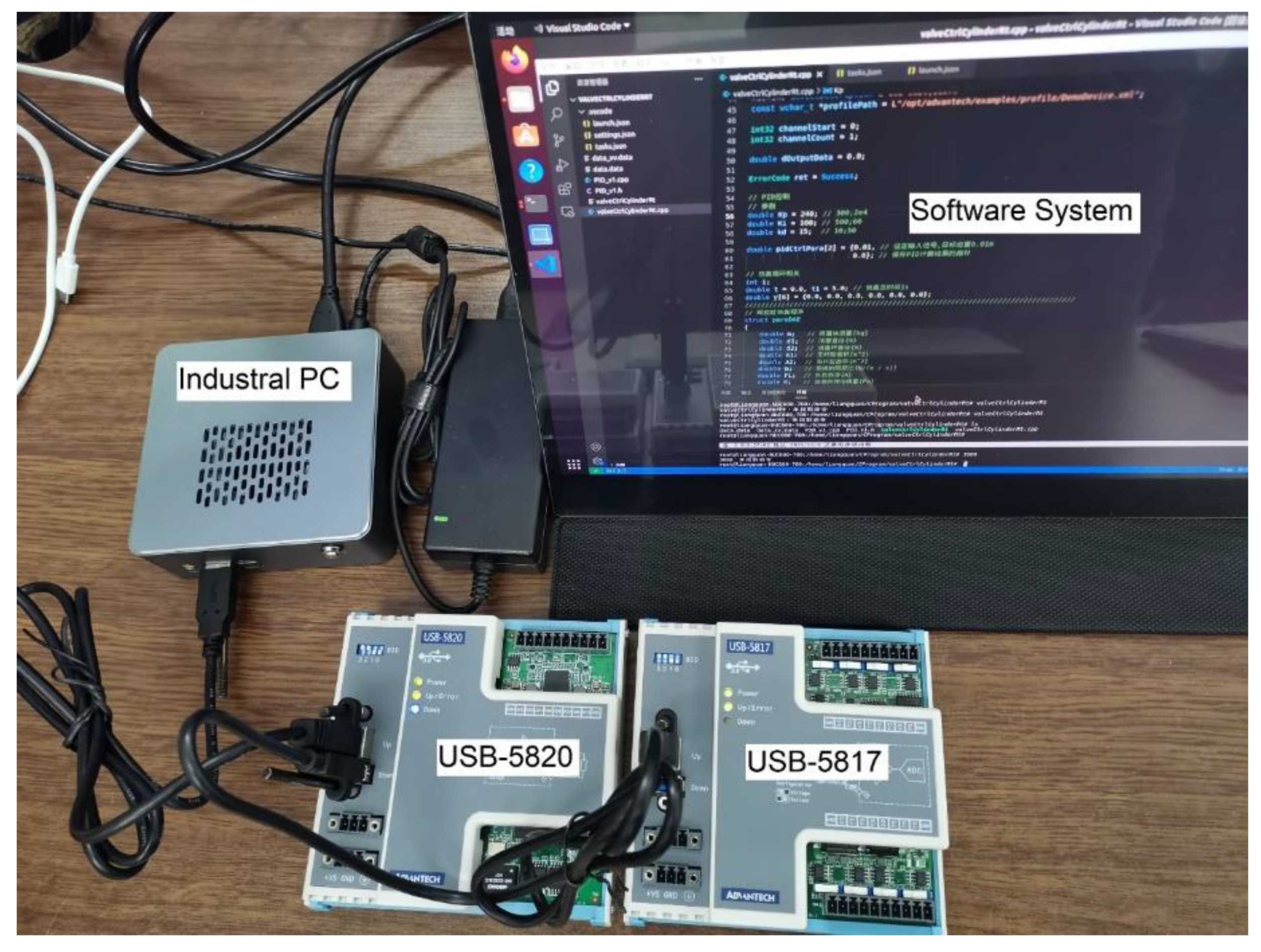
The hardware environment of the HIL simulation system was built on the Mini-ITX (Shenzhen R&S Core Control Electronic Technology Co., China) industrial PC with an Insein Intel/NUC control board. Advantech (Advantech Technology (China) Co., Beijing, China) USB-5820, 5817, and 4704 were selected as the data acquisition cards [37]. The reason for adopting these data acquisition cards is that they have a high precision (16 bits) and USB3.0 bus, while simultaneously guaranteeing portability, hot-swap ability, scalability, and an appropriate acquisition rate of the HIL simulation system.
There are three reasons to choose an Advantech data acquisition card: reasonable price, the inclusion of Linux drivers and biodaq library wrapped in C++ for low-level I/O operations. All these advantages guarantee the economy and feasibility of the HIL simulation system based on the Linux real-time kernel described in this paper.
The USB-5817 provides four single-ended analog input channels with a maximum allowable voltage of ±10 V and a current of 20 mA. The USB-5820 provides two analog output channels with a maximum allowable voltage of ±10 V and a current of 20 mA. The USB-4704 data acquisition card provides two 12-bit analog output channels, four 11-bit analog input channels, and eight isolated digital input and output channels with a TTL level.
Level mismatches (both analog and digital) may occur between the data acquisition card and the physical controller. In this case, the optical coupling can be added between the digital I/O port of the data acquisition card and the digital I/O port of the physical controller for level conversion. If the analog voltage values between the data acquisition card and the physical controller do not match, an amplifier can be added between the two.
The key of the HIL simulation is to replace the controlled object with the simulation model.
The replacement of a hydraulic servo system with HIL hardware is shown in Figure 6.
A joint degree of freedom in the exoskeleton system was taken as the control object, while a system of differential equations was used to describe the dynamic model of the valve-controlled 1-DOF joint. The system of the differential equations was transplanted into the HIL simulation platform developed in this paper as shown by the dash line in Figure 6. The hardware connection between the controller and the HIL simulation system was achieved by connecting the I/O card between the two as shown by the red line in Figure 6. Using this method, the controller could be directly ported to the physical exoskeleton system after successful debugging, which improves the development efficiency and avoids dangerous situations.

2.4.3. Software

The simulation model of the HIL system was written in C language. As mentioned above, the simulation model of the dynamic system is a system of first-order differential equations. The algorithm of solving these equations is realized by using C language to call an open-source scientific numerical algorithm library (GSL).
It should be mentioned that the performance of the timer will affect the HIL simulation system. With the help of the Linux RT Preempt wizard [9], the implementation of a high-precision timer in the Linux Preempt_RT environment should follow the following rules:
  • Real-time scheduling and priority;
  • Memory lock. Lock all pages mapped to the address space of the calling process to prevent this memory from being paged to the swap area;
  • Limit the power-saving state and state conversion of the processor. To prevent the system from going into the power-saving state and to provide the fastest idle state time, the kernel boots with the processor. Select max_cstate = 1 and idle = poll;
  • Disable the X window server and network interfaces.
If the above rules are followed, the real-time performance and accuracy of the HIL simulation system can be guaranteed.
The flow chart of the dynamic model solution is shown in Figure 7.
The flow chart of the controller nonlinear control algorithm is shown in Figure 8.
Combining the above hardware and software, a physical prototype of the HIL simulation system was built and is shown in Figure 9.

3. HIL Simulation and Experimental Results

3.1. Real-time Performance Test

To verify the performance of HIL simulation system developed in this paper, a real-time performance test under a high load was conducted.
Two types of experiments were designed. The first type was a real-time performance verification, which simply tests the accuracy of the real-time system timer. The second type was a full-model performance verification. A six-order nonlinear model of the valve-controlled hydraulic servo cylinder system was taken as the HIL simulation object to verify the real-time performance of the platform under computational load.
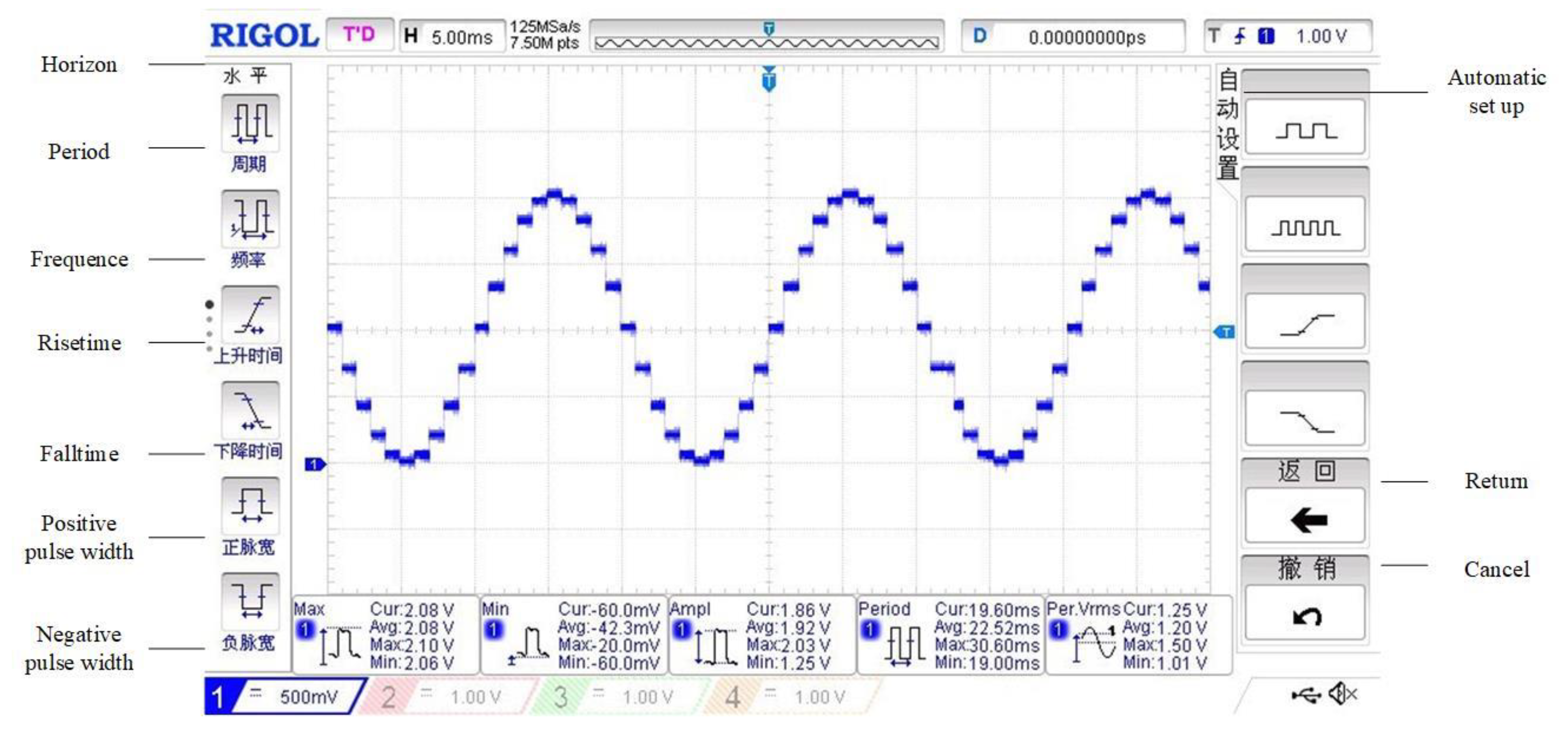
Square and sine wave tests were used to evaluate the real-time performance of the HIL simulation system. The tests were carried out in both Linux real-time system and Windows 10 (non-real-time) system. An oscilloscope was adopted to observe whether the generated waveform periods were accurate. To compare the real-time performances of the two operating systems, the test results are summarized in Table 1 and Table 2.
The tables show that the timer precision of a multithreaded program was better than that of the single-thread delay timer in both Windows and Linux with the real-time kernel.
An oscilloscope screenshot of the last experiment in Table 2 is shown in Figure 10.
In the same circumstances, the timing accuracy of the Linux real-time kernel was much better than that of Windows (see the last line of data in Table 2). In the case of the Linux real-time kernel, the error was within the order of tens to hundreds of microseconds (depending on the total period of the generating function), and the relative timing error was less than 2%. It was proved that the Linux real-time kernel scheme proposed in this paper was enough to meet the timer requirements of the HIL simulations.

3.2. A 1-DOF Joint HIL Simulation Test

In this section, the HIL simulations were performed to illustrate the effectiveness of the proposed control scheme. To verify the correctness of the HIL simulations, the parameters used by the simulations must be consistent. The key parameters of the full model simulation are listed in Table 3.
The desired trajectory of θ is given as θ d = 10 sin ( 2 π t ) . As such, by (33), the desired displacement of the piston x p d can be obtained accordingly. For illustration, θ and x p are shown in Figure 3. In addition, the setting parameters of the PID controller is shown in Table 4.
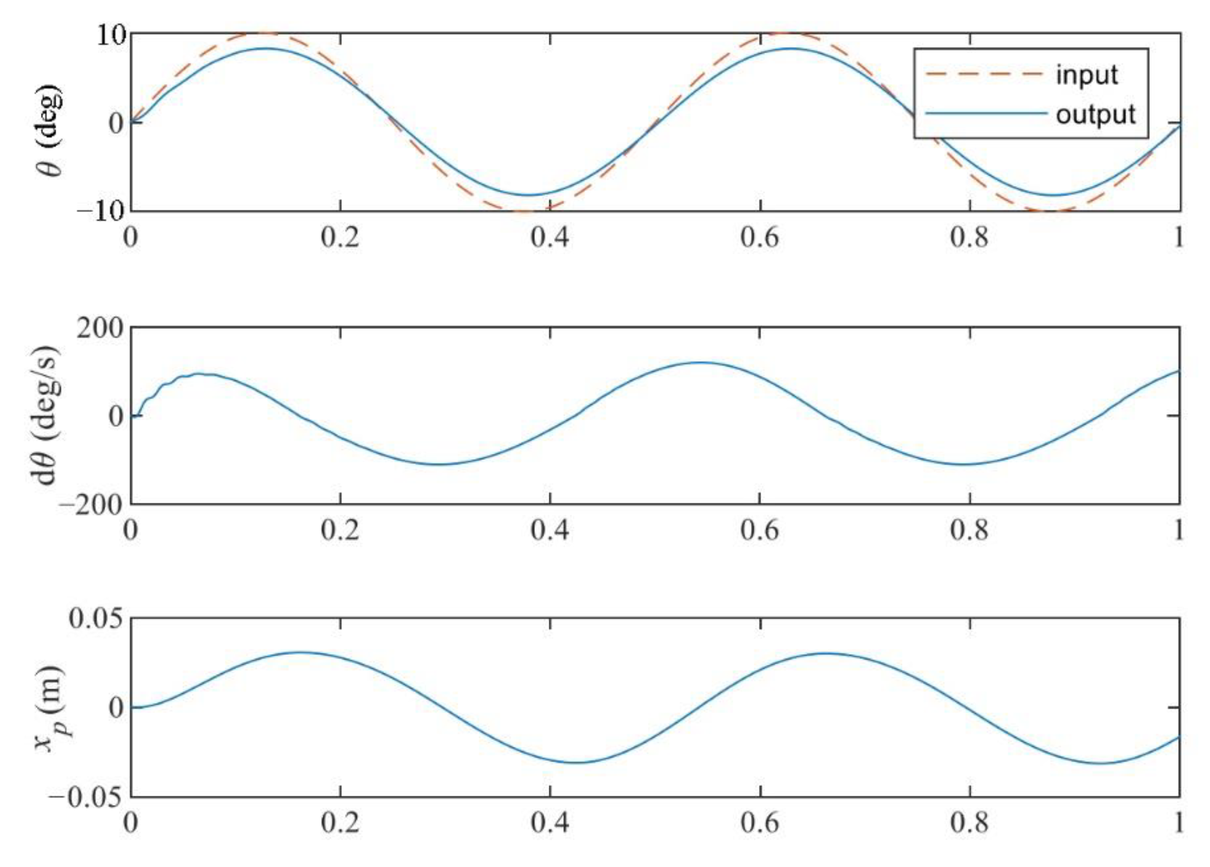
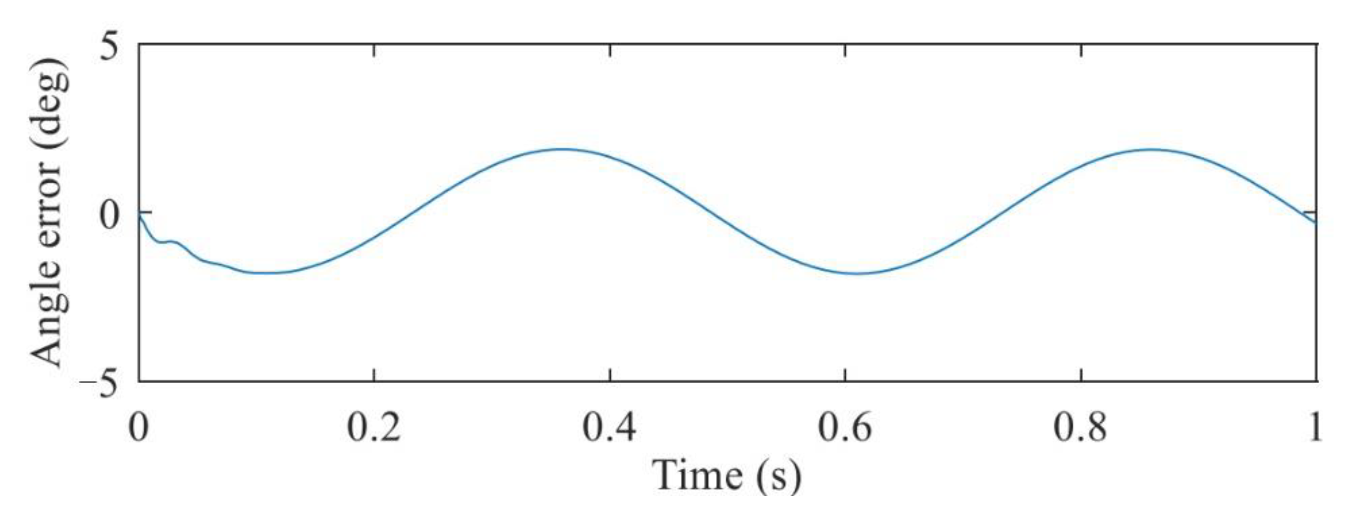
The tracking performance of the electro-hydraulic actuator system is demonstrated in Figure 11 and Figure 12.
From Figure 11, it can be observed that the PID control algorithm could not guarantee that the swing angle of the robot arm followed the changes of the input signal, and the load pressure fluctuated obviously in the initial stage of the operation.
As shown in Figure 12, there were large tracking errors in the system, which indicates again that the output of the system could not follow the input signal.
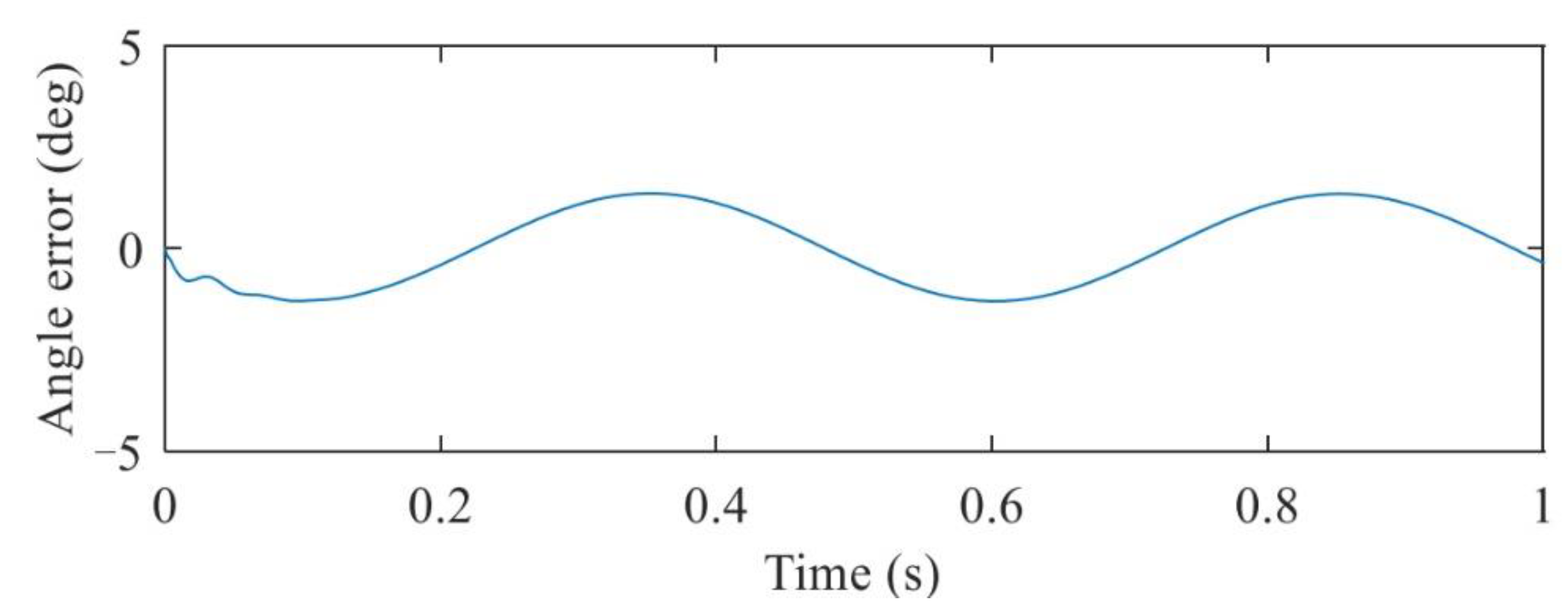
When the control parameters of the backstepping algorithm shown in Table 5 were used, the output and error curves of each state variable of the dynamic system are shown in Figure 13 and Figure 14.
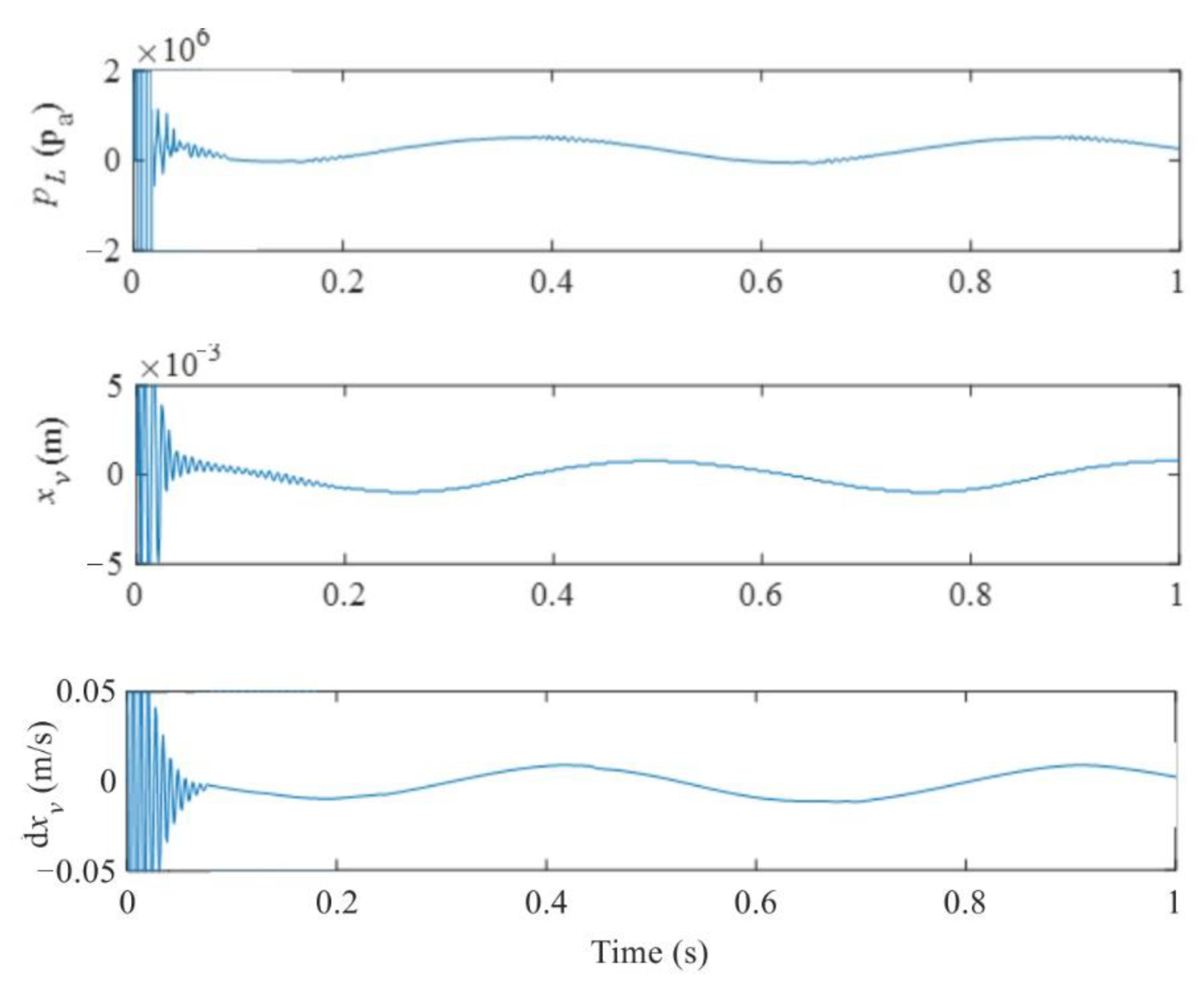
It can be observed from Figure 13 that when the control parameters of the backstepping algorithm were taken as the data in Table 5, it was still unable to guarantee that the swing angle of the robot arm output followed the changes of the input signal. However, compared with Figure 11, the changes in the load pressure of the system did not show more obvious fluctuation.
As shown in Figure 14, there were still large tracking errors in the system. This indicates that this method did not achieve good control effects under the control parameters in Table 5.
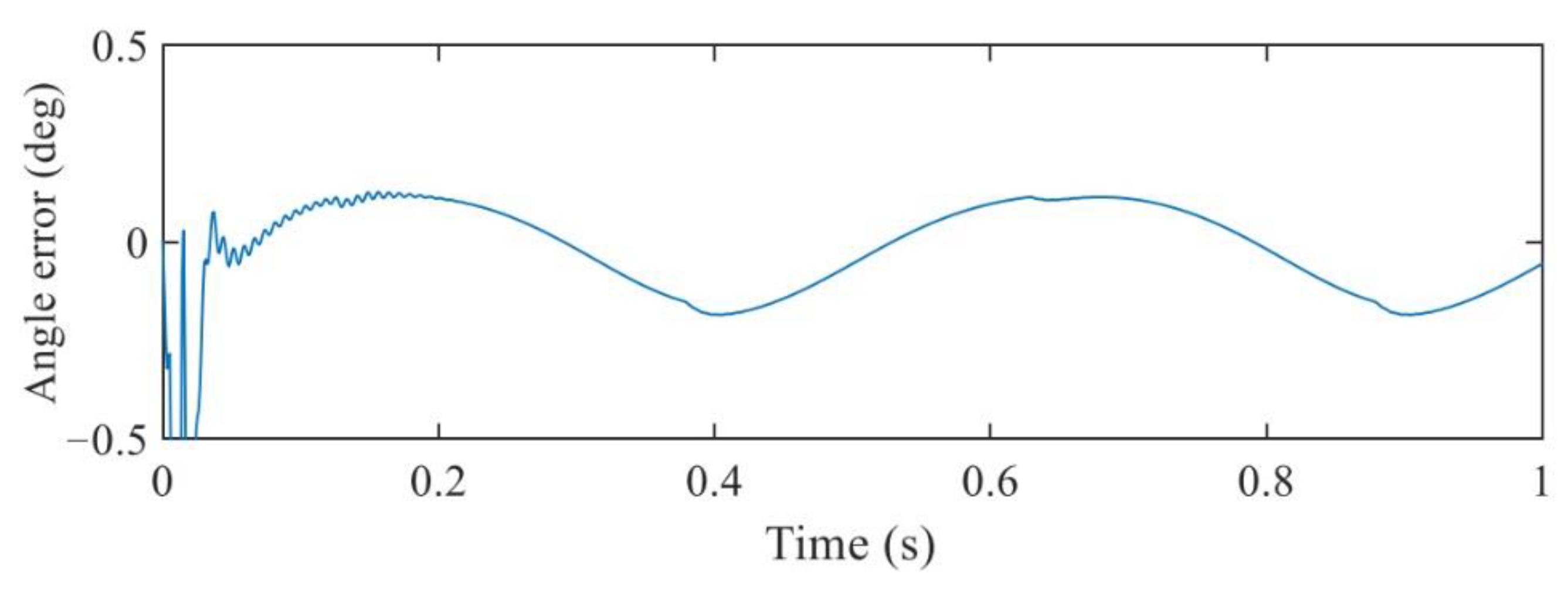
When the control parameters of the nonlinear backstepping algorithm took the values of the data shown in Table 6, the HIL simulation results of the system are shown in Figure 15 and Figure 16.
It can be seen from Figure 16 that the command and angle values matched more perfectly when the backstepping control parameters were taken as the data in Table 6. The angle error was maintained at about ±0.2° when the system entered the steady state. The results show that the backstepping algorithm realized the trajectory tracking control of the 1-DOF robot joint more perfectly.
From the above HIL simulation experimental process, in the experimental environment of the control algorithm development, the parameters of the control system can be adjusted arbitrarily, and there is no need to worry about the emergence of failure and damage to the physical test equipment (physical experimental object is a virtual simulation model). After the debugging is finished, the control system (with debugged control parameters) can be directly transplanted to the controlled physical equipment, so as to improve the development efficiency and reduce the cost and risk of control system development.

4. Conclusions

In this paper, the dynamic characteristics of the linkage mechanical system and the hydraulic servo system were integrated for consideration and the dynamic characteristic equations of the electro-mechanical–hydraulic integrated system were derived. The backstepping method in nonlinear control theory was applied to control the system, and the feasibility of the developed control system was proved by conducting HIL simulation tests on the self-developed HIL simulation platform.
In order to verify the effectiveness of the control algorithm, a hardware in the loop simulation platform was developed. The simulation platform took into account the economy and effectiveness. The differential equations of the electro-hydraulic system were numerically solved on the real-time Linux operating system, which completely simulated and replaced the physical system. Finally, the control algorithm was verified on the hardware in the loop simulation platform. By comparing the PID control algorithm with the non-linear control algorithm, it was concluded that the non-linear control algorithm was better than the PID control algorithm. In addition, on the hardware in the loop simulation platform developed in this paper, the controller parameters can be easily adjusted without worrying about any form of damage to the physical system. After the controller parameters were adjusted, the controller could be directly transplanted to the physical system to improve the development efficiency and reliability of the control algorithm. The research results of this paper have certain reference significance for the development of the similar control algorithms.
Through the hardware in the loop simulation experiment in this paper, it was proved that the developed hardware in the loop simulation platform was feasible. Comparing the research contents of reference [38], we introduced the Linux real-time hardware in the loop simulation platform, which reduced the cost. At the same time, on the hardware in the loop simulation platform, we developed a nonlinear control algorithm, which made up for the lack of research in reference [38].
The future research work of this paper will mainly focus on the following aspects: expanding the degree of freedom of the system to 2 to 3 degrees of freedom to better simulate the physical exoskeleton system; introducing the adaptive nonlinear control algorithm to make up for the problem that some system parameters are unknown to further improve the adaptability of the controller; and improving the robustness of the control algorithm to maintain the stability and control accuracy when the exoskeleton system is subjected to external forces.

Author Contributions

Methodology, Q.S. and Z.T.; validation, Q.S. and Z.T. investigation, Z.P.; data curation, Q.S., Z.T. and Z.P.; writing—original draft preparation, Q.S.; writing—review and editing, Z.T. All authors have read and agreed to the published version of the manuscript.

Funding

National Nature Science Foundation of China 51075017.

Institutional Review Board Statement

Not applicable.

Informed Consent Statement

Not applicable.

Data Availability Statement

The data used to support the findings of this study are included in the article.

Conflicts of Interest

The authors declare that they have no conflicts of interest.

References

  1. Zhu, Y.; Zhang, G.; Zhang, C.; Liu, G.; Zhao, J. Biomechanical modeling and load-carrying simulation of lower limb exoskeleton. Bio-Med. Mater. Eng. 2015, 26, S729–S738. [Google Scholar] [CrossRef] [PubMed] [Green Version]
  2. Wang, L.; Wang, S.; van Asseldonk, E.H.; van der Kooij, H. Actively controlled lateral gait assistance in a lower limb exoskeleton. In Proceedings of the 2013 IEEE/RSJ International Conference on Intelligent Robots and Systems, Tokyo, Japan, 3–7 November 2013; pp. 965–970. [Google Scholar]
  3. Luna, C.O.; Rahman, M.H.; Saad, M.; Archambault, P.; Zhu, W.H. Virtual decomposition control of an exoskeleton robot arm. Robotica 2016, 34, 1587–1609. [Google Scholar] [CrossRef]
  4. Brahmi, B.; Saad, M.; Rahman, M.H.; Ochoa-Luna, C. Cartesian trajectory tracking of a 7-DOF exoskeleton robot based on human inverse kinematics. IEEE Trans. Syst. Man Cybern. Syst. 2017, 49, 600–611. [Google Scholar] [CrossRef]
  5. Brahmi, B.; Driscoll, M.; El Bojairami, I.K.; Saad, M.; Brahmi, A. Novel adaptive impedance control for exoskeleton robot for rehabilitation using a nonlinear time-delay disturbance observer. ISA Trans. 2021, 108, 381–392. [Google Scholar] [CrossRef] [PubMed]
  6. Brahmi, B.; Saad, M.; Ochoa-Luna, C.; Rahman, M.H.; Brahmi, A. Adaptive tracking control of an exoskeleton robot with uncertain dynamics based on estimated time-delay control. IEEE/ASME Trans. Mechatron. 2018, 23, 575–585. [Google Scholar] [CrossRef]
  7. Brahim, B.; Maarouf, S.; Luna, C.O.; Abdelkrim, B.; Rahman, M.H. Adaptive iterative observer based on integral backstepping control for upper extremity exoskelton robot. In Proceedings of the IEEE 2016 8th International Conference on Modelling, Identification and Control (ICMIC), Algiers, Algeria, 15–17 November 2016; pp. 886–891. [Google Scholar]
  8. Tschiersky, M.; Hekman, E.E.; Brouwer, D.M.; Herder, J.L.; Suzumori, K. A compact McKibben muscle based bending actuator for close-to-body application in assistive wearable robots. IEEE Robot. Autom. Lett. 2020, 5, 3042–3049. [Google Scholar] [CrossRef] [Green Version]
  9. Xie, D.; Liu, J.; Zuo, S. Pneumatic Flexible Exoskeleton with Variable Stiffness Based on Wire Driving and Clamping. In Proceedings of the 2019 IEEE 9th Annual International Conference on CYBER Technology in Automation, Control, and Intelligent Systems (CYBER), Suzhou, China, 29 July–2 August 2019; pp. 1215–1218. [Google Scholar]
  10. Di Natali, C.; Sadeghi, A.; Mondini, A.; Bottenberg, E.; Hartigan, B.; De Eyto, A.; O’Sullivan, L.; Rocon, E.; Stadler, K.; Mazzolai, B.; et al. Pneumatic quasi-passive actuation for soft assistive lower limbs exoskeleton. Front. Neurorobotics 2020, 6, 30. [Google Scholar] [CrossRef] [PubMed]
  11. Henderson, G.C.; Ueda, J. Pneumatically-powered robotic exoskeleton to exercise specific lower extremity muscle groups in humans. In Proceedings of the 2012 4th IEEE RAS & EMBS International Conference on Biomedical Robotics and Biomechatronics (BioRob), Rome, Italy, 24–27 June 2012; pp. 1506–1511. [Google Scholar]
  12. Zhang, X.; Jiang, W.; Li, Z.; Song, S. A hierarchical Lyapunov-based cascade adaptive control scheme for lower-limb exoskeleton. Eur. J. Control 2019, 50, 198–208. [Google Scholar] [CrossRef] [Green Version]
  13. Liu, X.; Zhang, S.; Liu, S.; Xu, K.; Yao, B. Adaptive Backstepping Sliding Mode Control for a Hydraulic Knee Exoskeleton Robot. In Proceedings of the 2020 2nd International Conference on Artificial Intelligence, Robotics and Control, Cairo, Egypt, 12–14 December 2020; pp. 43–48. [Google Scholar]
  14. Chen, S.; Yao, B.; Zhu, X.; Chen, Z.; Wang, Q.; Zhu, S.; Song, Y. Adaptive robust backstepping force control of 1-dof joint exoskeleton for human performance augmentation. IFAC-PapersOnLine 2015, 48, 142–147. [Google Scholar] [CrossRef]
  15. Glowinski, S.; Krzyzynski, T.; Bryndal, A.; Maciejewski, I. A kinematic model of a humanoid lower limb exoskeleton with hydraulic actuators. Sensors 2020, 20, 6116. [Google Scholar] [CrossRef] [PubMed]
  16. Yang, Y.; Zhao, D.; Ma, L.; Zhu, Q.; Huang, D. Backstepping trajectory tracking control of electro-hydraulic actuators of lower limb load exoskeleton. In Proceedings of the IECON 2016-42nd Annual Conference of the IEEE Industrial Electronics Society, Florence, Italy, 23–26 October 2016; pp. 6073–6078. [Google Scholar]
  17. Yang, J. Design and experiment of the lower extremity exoskeleton. In Proceedings of the 2017 IEEE 2nd Advanced Information Technology, Electronic and Automation Control Conference (IAEAC), Chongqing, China, 25–26 March 2017; pp. 1380–1383. [Google Scholar]
  18. Yang, Y.; Ma, L.; Huang, D. Development and repetitive learning control of lower limb exoskeleton driven by electrohydraulic actuators. IEEE Trans. Ind. Electron. 2016, 64, 4169–4178. [Google Scholar] [CrossRef]
  19. Glowinski, S.; Obst, M.; Majdanik, S.; Potocka-Banaś, B. Dynamic model of a humanoid exoskeleton of a lower limb with hydraulic actuators. Sensors 2021, 21, 3432. [Google Scholar] [CrossRef] [PubMed]
  20. Chen, S.; Chen, Z.; Yao, B. Precision cascade force control of multi-DOF hydraulic leg exoskeleton. IEEE Access 2018, 6, 8574–8583. [Google Scholar] [CrossRef]
  21. Liu, T.; Yao, J.; Liu, X.; Li, L. Disturbance rejection control for single-rod electro-hydraulic servo system based on dual-extended-state-observer. In Proceedings of the IECON 2017-43rd Annual Conference of the IEEE Industrial Electronics Society, Beijing, China, 29 October–1 November 2017; pp. 3032–3037. [Google Scholar]
  22. Guo, Q.; Yu, T.; Jiang, D. High-gain observer-based output feedback control of single-rod electro-hydraulic actuator. IET Control. Theory Appl. 2015, 9, 2395–2404. [Google Scholar] [CrossRef]
  23. Tian, L.; Qian, L.; Chen, L.; Zhang, W. Sliding mode control based on backstepping method for electro-hydraulic single-rod actuator. In Proceedings of the 2015 IEEE International Conference on Information and Automation, Lijiang, China, 8–10 August 2015; pp. 2326–2329. [Google Scholar]
  24. Wang, J.; Ai, P.; Zhang, J.; Chen, W.; Chen, W. An Adaptive Backstepping Control Method for Lower-Limb Exoskeleton Robot. In Proceedings of the 2020 15th IEEE Conference on Industrial Electronics and Applications (ICIEA), Kristiansand, Norway, 9–13 November 2020; pp. 574–578. [Google Scholar]
  25. Khamar, M.; Edrisi, M. Designing a backstepping sliding mode controller for an assistant human knee exoskeleton based on nonlinear disturbance observer. Mechatronics 2018, 54, 121–132. [Google Scholar] [CrossRef]
  26. Sun, J.; Wang, J.; Yang, P.; Geng, Y. Model-free fractional-order adaptive back-stepping prescribed performance control for wearable exoskeletons. Int. J. Intell. Robot. Appl. 2021, 5, 590–605. [Google Scholar] [CrossRef]
  27. Chen, Z.; Guo, Q.; Xiong, H.; Jiang, D.; Yan, Y. Control and Implementation of 2-DOF Lower Limb Exoskeleton Experiment Platform. Chin. J. Mech. Eng. 2021, 34, 14–30. [Google Scholar] [CrossRef]
  28. Zaev, E.; Babunski, D.; Tuneski, A.; Rath, G. Hardware-in-the-loop for simulation of hydraulic servo systems and their control. In Proceedings of the IEEE 2017 6th Mediterranean Conference on Embedded Computing (MECO), Bar, Montenegro, 11–15 June 2017; pp. 1–4. [Google Scholar]
  29. Yong, J.; Gao, F.; Ding, N.; He, Y. Design and validation of an electro-hydraulic brake system using hardware-in-the-loop real-time simulation. Int. J. Automot. Technol. 2017, 18, 603–612. [Google Scholar] [CrossRef]
  30. Lim, T.H.; Cho, H.C.; Lee, H.S.; Yang, S.Y. Development of Hardware In the Loop System (HILS) for Hydraulic Excavator. In Proceedings of the IEEE 22nd International Symposium on Automation and Robotics in Construction ISARC 2005, Ferrara, Italy, 11–14 September 2015; pp. 11–14. [Google Scholar]
  31. Karpenko, M.; Sepehri, N. Electrohydraulic force control design of a hardware-in-the-loop load emulator using a nonlinear QFT technique. Control. Eng. Pract. 2012, 20, 598–609. [Google Scholar] [CrossRef]
  32. Lv, C.; Zhang, J.; Li, Y.; Sun, D.; Yuan, Y. Hardware-in-the-loop simulation of pressure-difference-limiting modulation of the hydraulic brake for regenerative braking control of electric vehicles. Proc. Inst. Mech. Eng. Part D J. Automob. Eng. 2014, 228, 649–662. [Google Scholar] [CrossRef]
  33. Manring, N.D.; Fales, R.C. Hydraulic Control Systems; John Wiley & Sons: Hoboken, NJ, USA, 2019. [Google Scholar]
  34. Jazar, R.N. Theory of Applied Robotics: Kinematics, Dynamics, and Control; Springer Science & Business Media: Berlin, Germany, 2010. [Google Scholar]
  35. Gungor, G.; Turhan, M.H.; Jamshidifar, H.; Fidan, B. Online estimation and compensation of friction in industrial cable robot manipulation. IFAC-PapersOnLine 2015, 48, 1332–1337. [Google Scholar] [CrossRef]
  36. Advantech. Available online: https://www.advantech.com.cn/ (accessed on 10 June 2022).
  37. Preempt_RT. Available online: https://wiki.linuxfoundation.org/realtime/documentation/start/howtos (accessed on 10 June 2022).
  38. Linjama, M.; Virvalo, T.; Gustafsson, J.; Lintula, J.; Aaltonen, V.; Kivikoski, M. Hardware-in-the-loop environment for servo system controller design, tuning and testing. Microprocess. Microsyst. 2000, 24, 13–21. [Google Scholar] [CrossRef]
Figure 1. Mechanical structure of the exoskeleton. (a) Three-dimensional model. (b) Wearing the schematic diagram. (c) Linkage structure.
Machines 10 00607 g001
Figure 2. DOFs of the exoskeleton.
Machines 10 00607 g002
Figure 3. Schematic diagram of the 1-DOF joint system.
Machines 10 00607 g003
Figure 4. A link (i) and its vectorial kinematic characteristics.
Machines 10 00607 g004
Figure 5. Hardware and software architecture of the HIL simulation system.
Machines 10 00607 g005
Figure 6. Replacement of a hydraulic servo system with HIL hardware.
Machines 10 00607 g006
Figure 7. The flow chart of the dynamic equation resolution.
Machines 10 00607 g007
Figure 8. The flow chart of the control algorithm implementation of the controller.
Machines 10 00607 g008
Figure 9. Physical HIL simulation system prototype.
Machines 10 00607 g009
Figure 10. Oscilloscope screenshot of the test result.
Machines 10 00607 g010
Figure 11. HIL simulation curves with PID control.
Machines 10 00607 g011aMachines 10 00607 g011b
Figure 12. HIL simulation error curve with PID control.
Machines 10 00607 g012
Figure 13. Backstepping HIL simulation curve (first set of control parameters).
Machines 10 00607 g013
Figure 14. Backstepping HIL simulation error curve (first set of control parameters).
Machines 10 00607 g014
Figure 15. Backstepping HIL simulation curve (second set of control parameters).
Machines 10 00607 g015aMachines 10 00607 g015b
Figure 16. Backstepping HIL simulation error curve (second set of control parameters).
Machines 10 00607 g016
Table 1. Real-time test of the Windows system.
Thread TypeWaveformTimer Period (ms)Generated Function Period (ms)Average Value
(ms)
Maximum Value
(ms)
Minimum Value
(ms)
Single threadSquare wave(sleep function)122.6454.7012.505
MultithreadSquare wave(high-resolution timer)122.0072.1951.820
MultithreadSquare wave(calculated load)122.0102.4951.945
Table 2. Real-time test of the Linux system with the real-time kernel.
Thread TypeWaveformTimer Period (ms)Generated Function Period(ms)Average Value
(ms)
Maximum Value
(ms)
Minimum Value
(ms)
MultithreadSquare122.0032.0751.930
MultithreadSquare wave (calculated load)122.0002.0351.940
Single threadSine wave
(sleep function)
15.65.2267.5203.750
MultithreadSine wave15656.1856.2054.80
Table 3. Key parameters of the whole model verification.
ParameterValueUnitSpecification
D 0.02mPiston diameter
d 0.01mRod diameter
α 0.75 Area ratio
C d 0.625 Orifice flow coefficient
d v 0.01mValve spool diameter
w 0.0314mValve area gradient
V h 1 2.20 × 10⁴m3Initial volume of piston chamber
V h 2 1.65 × 10⁴m3Initial volume of rod chamber
ω v 628rad/sNatural frequency of valve
ζ v 0.7 Damper of valve
k q 0.2m/sFlow gain of valve
S 0.14mCylinder stroke
ρ 870kg/m3Oil density
p s 21MPaSupply pressure
p t 0MPaReturn pressure
β e 7 × 10⁸PaElastic modulus of oil
k v 3.33 × 10⁻²m3/s/AServo valve gain
m 6.4kgMass of robot arm
l 1 0.322mFixed end length 1
l 2 0.06mFixed end length 2
θ 0 90deg.Initial angle of robot arm
g 9.81kg m/s2Gravitational acceleration
L 0.466mLength of robot arm
I z 3.02kg m2Rotational inertia of robot arm
F N 10NNormal force
μ v 0.5s/mViscous friction coefficient
μ c 1 Coulomb friction coefficient
k 1 × 10³s/mSteepness of coulomb friction curve
Table 4. Parameters of the PID controller.
SymbolValue
k P 25
k I 265
k D 2
Table 5. The first set of backstepping control parameters.
SymbolValue
k 1 200
k 2 80
k 3 100
k 4 280
k 5 80
Table 6. The second set of backstepping control parameters.
SymbolValue
k 1 200
k 2 200
k 3 400
k 4 400
k 5 40
Publisher’s Note: MDPI stays neutral with regard to jurisdictional claims in published maps and institutional affiliations.