1. Introduction
The correct operation of a large synchronous generator is very important in a power system [
1]. The single-phase grounding fault of generator stator winding is the most common fault of a generator. With the increase of generator unit capacity, the corresponding single-phase grounding current also increases [
2,
3]. For large water turbine units, the stator winding has a large capacitance to ground. Once a single-phase grounding fault of stator winding occurs in the unit, the strong fault current will cause great damage to the water turbine generator unit. In order to limit the fault current and fault time, the water turbine generator unit is usually equipped with a neutral grounding device to protect the generator and its end equipment and prevent the expansion of fault damage range. However, the operation status of the unit shows that after the neutral point of large capacity hydro generator is equipped with a grounding device, the problem of neutral point voltage drift becomes more and more prominent, which brings hidden dangers to the safe and stable operation of the generator and connected power grid system [
4].
The #1 unit of a power plant has a rated capacity of 210MVA. Due to the high neutral point offset during normal operation, the generator stator grounding protection misoperated, resulting in a unit trip accident. The fundamental cause of neutral point voltage drift during the operation of a hydro generator is the imbalance of generator capacitance to ground [
5]. Moreover, with the increasing capacity of hydraulic turbine units put into use in recent years, the unit asymmetry is also increasing, which leads to the increase of the imbalance of unit capacitance current to ground, and then leads to the more serious phenomenon of neutral point voltage drift. The significant increase of neutral voltage drift will affect the safe and stable operation of the generator to a certain extent, and it is easy to cause single-phase grounding fault of stator winding. When the stator winding single-phase grounding fault occurs, the neutral point will also produce high transient displacement voltage, which is not only very unfavorable to the safe and stable operation of the generator and the connected power grid system, but also a serious threat to the insulation safety of the generator. Therefore, for large hydro generators, research on the dynamic characteristics of stator winding under single-phase grounding fault has gradually become the focus of and challenge for scholars in the industry [
6,
7,
8].
At present, some research is being carried out on the dynamic characteristics of single-phase grounding fault of a hydro generator stator winding at home and abroad. P. G. Brown and others first put forward the transient simulation analyzer (TNA) model [
9], and our peers put forward some improved models [
10], but the above research methods are based on the lumped capacitance parameter model, and the physical parameters are more simplified, which will bring unavoidable errors. In order to solve this problem, Li Ruliang and others proposed a quasi-distributed capacitance parameter model based on Pspice simulation, which divides the stator winding into multiple circuit units [
11,
12], and the distributed capacitance of the stator winding to the ground is equivalent to the quasi distributed form. Then, Zhang Qixue and others used the multi loop transient analysis model to calculate the transient overvoltage and fault current when the neutral point of large hydro generator is grounded through high resistance and an arc suppression coil [
13,
14]. In addition, the selection and design of grounding equipment are discussed in documents [
15,
16,
17], wherein some useful results are presented. However, the above research does not involve the dynamic characteristics of neutral voltage drift, and does not study the dynamic process of single-phase grounding fault under combined grounding mode, so comprehensive state parameters of the fault process cannot be obtained.
In view of the above problems, based on the previous research results, using the idea of quasi-distributed parameter capacitance and taking the neutral point grounding mode as the starting point, this paper establishes the fault equivalent model of a large capacity hydro generator; simulates the single-phase grounding fault of stator winding; and analyzes the dynamic characteristics of grounding fault current, transient overvoltage, and neutral point drift under different neutral point grounding modes. A transient analysis method of neutral point voltage drift under single-phase grounding fault of stator winding of large hydro generator is proposed. Using this method, the dynamic characteristics of neutral point voltage drift under single-phase grounding fault of stator winding of a Baihetan 1000 MW hydro generator (completed on 28 June 2021, the largest hydropower project under construction in the world) are analyzed, and the state parameters of generator under single-phase grounding fault are obtained. According to the model and transient analysis method, considering many factors such as frequency offset, the influence law of different grounding modes on the neutral point voltage drift of large hydro generator is obtained.
2. Establishment of Single-Phase Grounding Fault Model
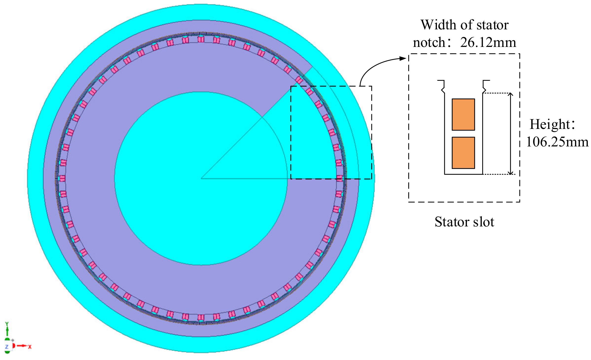
The 1000 MW hydro generator is different from the conventional generator. The current passing through its stator winding is larger, which requires a larger conductor section.
Figure 1 shows the structural section of the 1000 MW hydro generator stator winding. This figure shows the type and size of stator winding slot in detail.
This paper mainly addresses the dynamic process of a single-phase grounding fault in the stator winding of a large hydro generator. Regardless of the non-main influencing factors, the following assumptions can be made:
The saturation effect of neutral distribution transformer is ignored;
Grounding fault and fault elimination are replaced by arc burning and arc extinguishing, which are simulated by the connection and disconnection of electronic switches;
Each phase winding is divided into multiple unit circuits, and its leakage inductance, resistance, and electromotive force are evenly distributed in each unit circuit;
The capacitance between stator windings is ignored, the capacitance to ground of three-phase windings is evenly distributed, and the capacitance to ground is not completely equal to each other;
It is assumed that the three-phase voltages VA, VB, and VC of the generator are completely symmetrical.
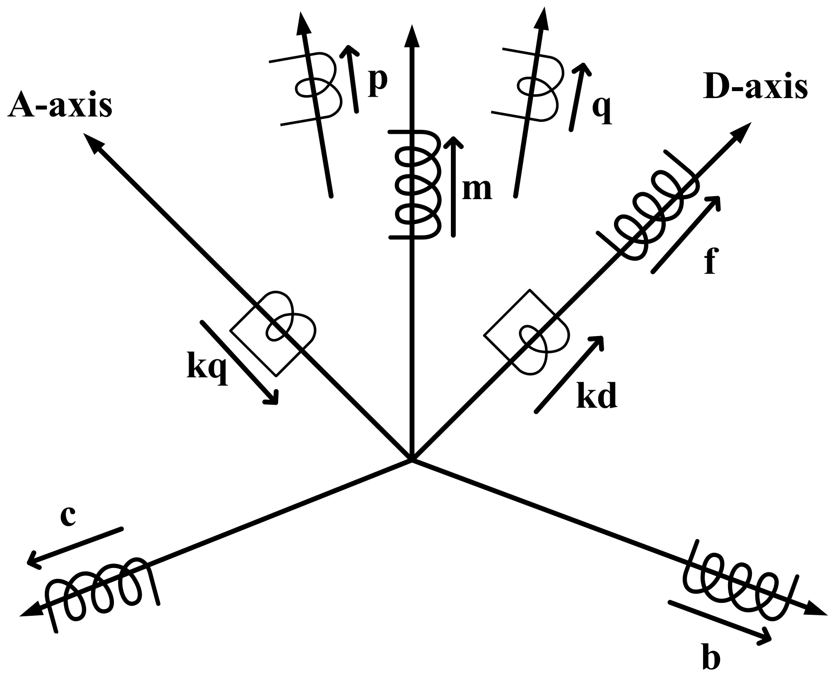
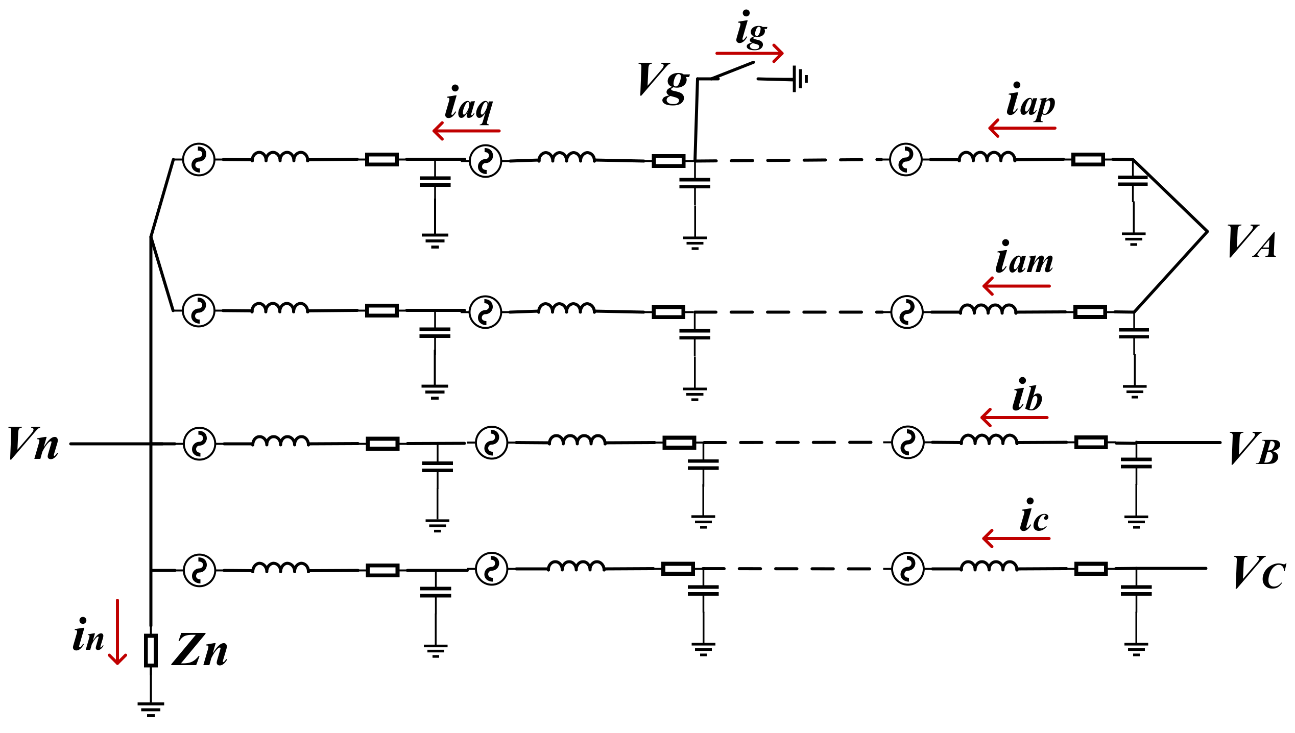
Figure 2 and
Figure 3 show the internal schematic diagram of the hydro generator in the case of stator winding failure. Phase A in the figure is the fault phase, and its fault branch is divided into two parts by the fault point: the branch near the machine end is p winding, and the branch near the neutral point is q winding; its non-fault branch set is equivalent to m winding. Phase B and phase C are sound phases, which are equivalent to windings B and C, respectively. f, kd, and kq are the serial number of the rotor winding circuit. Different forms of neutral grounding are equivalent to different grounding impedance. The positive direction of each winding, winding current, and voltage serial number are shown in
Figure 2 and
Figure 3.
The stator winding potential matrix is defined as
Vs-
Vn, the potential at the neutral point is
Vn, the rotor loop potential matrix is
Vr, the electromotive force of rotor is
ef, the flux linkage matrix is ψ, the stator winding resistance matrix is
Rs, the rotor winding resistance matrix is
Rr, the instantaneous value matrix of stator current is
Is, and the instantaneous value matrix of rotor current is
Ir. The voltage equation [
18] is
where
L is self-inductance coefficient and
M is the mutual inductance coefficient. Each subscript represents different circuits, where q, p, m, b, and c represent the serial number of the stator winding circuit. f, k
d, and k
q are the serial number of the rotor winding circuit. When a single-phase grounding fault occurs in the stator winding of hydro generator,
The motion equation of hydro generator during operation is
where,
ω is the angular speed of rotor rotation; δ is the load angle with reference to the infinite bus;
H is the moment of inertia; p is the differential operator,
Tmec is the input mechanical torque; and
Tele is electromagnetic torque.
3. Research Object
Equations (1)–(15) constitute the simulation model of single-phase grounding fault of stator winding of a hydro generator. According to the fault dynamic characteristics under different neutral grounding modes, this paper takes the 1000 MW large hydro generator of Baihetan Hydropower Station as the research object for analysis and calculation. It is a 56-stage salient pole synchronous generator. Its main parameters are shown in
Table 1.
After continuous development, at present, the neutral point grounding modes of large hydro generators at home and abroad are mainly divided into three types, and the scope of application of the three different modes is different. Scholars at home and abroad have different views on the three grounding modes [
19,
20]. Therefore, this paper analyzes the fault dynamic characteristics of voltage and current in the motor under three different grounding modes.
The device parameters of three different grounding modes of neutral point were selected as follows:
The neutral point is grounded through the high resistance of the grounding transformer [
21], and the primary side of the neutral point grounding resistance is equivalent to
R:
When the neutral point is grounded through the arc suppression coil, the equivalent value of the neutral point grounded arc suppression coil is
L:
In the case of combined neutral grounding, in order to limit the fault current not to exceed 25A and the neutral grounding resistance current not to exceed the compensated capacitance current, the resistance current and inductance current at the primary side of the grounding transformer can be obtained as follows [
22]:
wherein the capacitive current is
Considering that the transformer is an ideal transformer, it can be determined that the resistance connected to the grounding transformer is 0.42 and the inductance is 0.6 mh; when equivalent to the primary side of the neutral point grounding, these values are as follows:
4. Fault Analysis
4.1. Fault Current Analysis of the Stator
The stator winding of the water turbine generator set has large capacitance to ground. Once a single-phase grounding fault occurs in the stator winding of the unit, the strong fault current will cause great damage to the hydro generator unit.
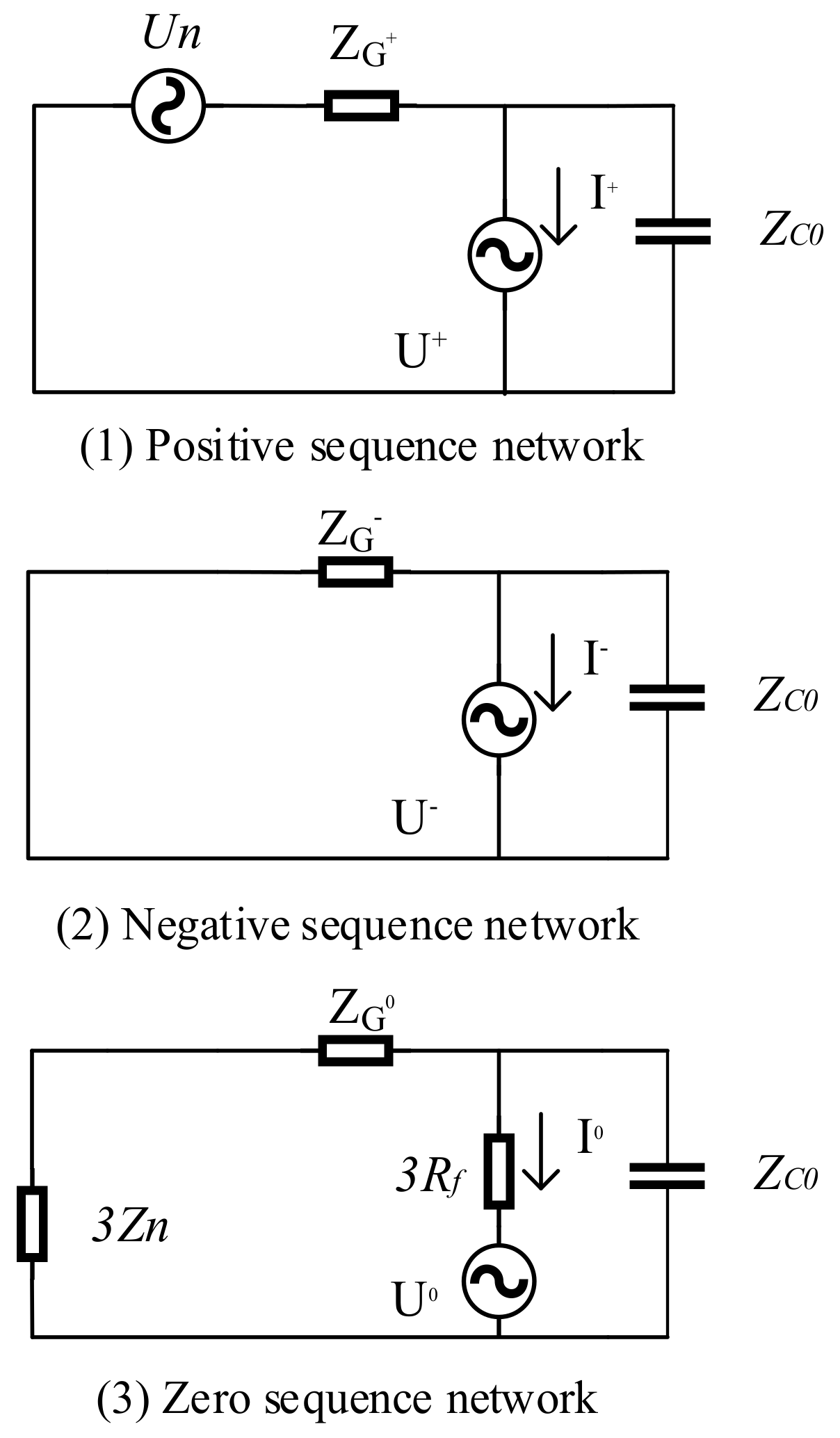
Figure 4 shows the positive sequence, negative sequence, and zero sequence equivalent circuits of hydro generator in the case of single-phase grounding fault of stator winding.
In the figure,
ZG is the generator subtransient reactance and
Rf is the transition resistance of short-circuit phase. From
Figure 4, the formulas under positive sequence, negative sequence, and zero sequence networks can be listed as follows:
Assuming a single phase to ground fault occurs in phase a, then
The available short-circuit current is
Since
ZC0 and
Zn are much larger than
ZG and
Rf, then
where
CΣ is the grounding capacitance of the generator voltage system,
Zn is the equivalent impedance value of the neutral grounding device, and
UN is the rated phase voltage of the generator. It can be seen from Equation (28) that when a single-phase grounding fault occurs in the hydro generator, the fault current value is the superposition value of the grounding capacitance current and the neutral point current. Therefore, if the neutral grounding device contains inductance, it can compensate part of the capacitive current and play a great role in reducing the grounding fault current.
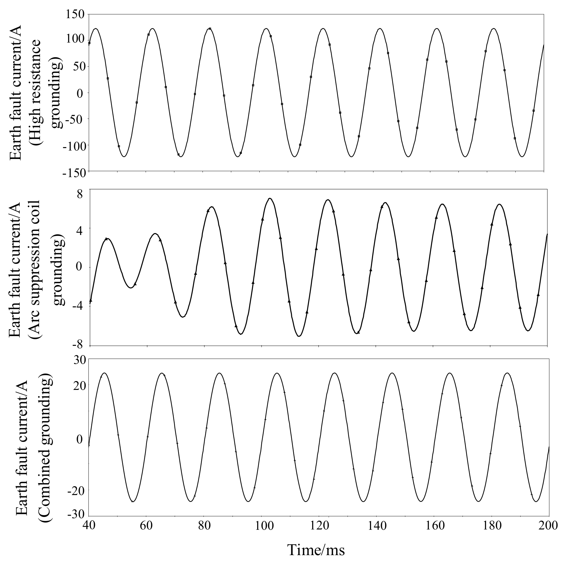
Assuming that metallic grounding occurs when phase a at the turbine end of the hydro generator reaches its peak value, the waveform of grounding fault current under three different grounding modes is shown in
Figure 5 (excluding the current peak at the moment of grounding).
It can be seen from
Figure 5 that in the case of single-phase grounding fault of the hydro generator, arc suppression coil grounding has the best suppression characteristics on fault grounding current among the three grounding modes, followed by combined grounding. The high-resistance grounding fault current is the largest, far exceeding the specified value of 25 A, because it does not compensate the capacitive current. Therefore, it is necessary to reasonably select the grounding inductance value to compensate the capacitive current.
4.2. Fault Transient Overvoltage
After the stator winding grounding fault occurs, if the arc extinguishing occurs when the current at the fault point reaches the zero point, the recovery voltage may exceed the voltage peak during normal operation after a period of time, the voltage may exceed the original peak for a long period of time, and arcing may occur again in these periods of time.
The traditional research methods cannot analyze the dynamic process of overvoltage during fault; the transient analysis method can better calculate and obtain more accurate and comprehensive data. Therefore, the single-phase grounding fault model is used here to analyze the transient overvoltage.
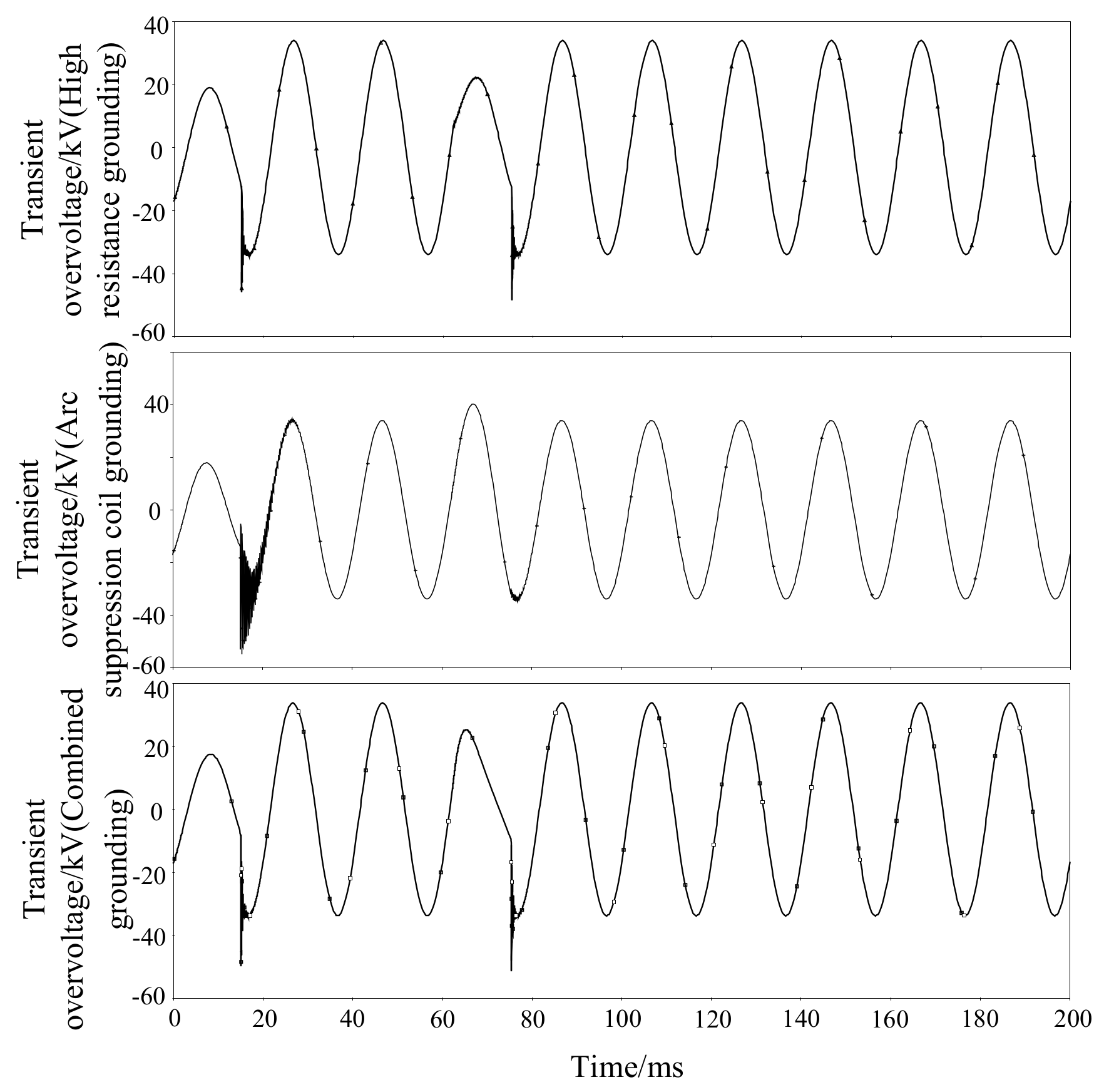
It is assumed that metallic grounding occurs when phase a at the turbine end reaches its peak value, and the grounding time lasts for two cycles. After two cycles, the fault disappears when the fault current drops to zero, and then the secondary grounding fault occurs when the fault phase voltage recovers to the amplitude.
Figure 6 shows the transient overvoltage waveform in the case of a single-phase grounding fault.
It can be seen from
Figure 6 that in case of a single-phase grounding fault of stator winding of the hydro generator, the suppression characteristics of arc suppression coil grounding on transient overvoltage are the worst among the three grounding modes, and its transient overvoltage is far more than 2.6 times the phase voltage. Therefore, in the neutral point grounding device of a 1000 MW large hydro generator, the grounding resistance value should be reasonably selected to suppress the transient overvoltage in the process of fault.
4.3. Neutral Voltage Drift
4.3.1. Dynamic Characteristics of Neutral Point Voltage under Single-Phase Grounding Fault
In order to analyze the dynamic characteristics of neutral point voltage after a single-phase grounding fault of a 1000 MW large hydro generator, the dynamic characteristics of neutral point voltage drift when stator winding single-phase grounding fault occurs under three different neutral point grounding modes are analyzed here using the transient analysis method.
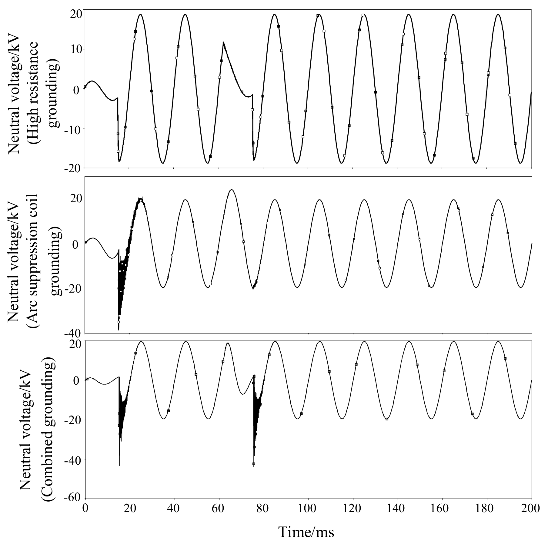
It is assumed that a single-phase grounding fault occurs in phase a of generator stator winding when the phase voltage reaches its peak value, and the fault grounding arc resistance is set to zero.
Figure 7 shows the simulation waveform of neutral point displacement voltage of the 1000 MW hydro generator under three different grounding modes.
It can be seen from
Figure 7 that in the case of a single-phase grounding fault of the hydro generator, the neutral point voltage has a sharp peak in its grounding transient process. Compared with the two traditional grounding modes, the combined grounding mode will increase the transient peak value of neutral point displacement voltage, and the transient peak value of voltage can reach 40.495 kV, twice the steady-state value.
For the existing hydro generator protection methods, most of them still use the fundamental zero sequence voltage and the third harmonic voltage protection, and in the actual operation process, the stator winding fault grounding transition resistance is not 0. An analysis of neutral point voltage drift under three different neutral point grounding modes when the stator winding is single-phase grounded through 8000 Ω transition resistance is shown in
Figure 8.
It can be seen from
Figure 8 that when the stator winding of the 1000 MW hydro generator is grounded through 8000 Ω transition resistance, for high-resistance grounding and combined grounding, the change of voltage on both sides before and after the fault is not as large as that when it is grounded through an arc suppression coil. In other words, for the fundamental zero sequence voltage protection criterion, the protection sensitivity of neutral point through high-resistance grounding and combined grounding is not as high as that of arc suppression coil grounding.
4.3.2. Influence of Frequency Offset on Neutral Voltage Drift
The change of frequency is related to the active power balance of the whole power system. When the hydro generator is under the conditions of startup, shutdown, sudden overload, and load rejection, the frequency may deviate from the normal rated value. Therefore, the neutral point voltage drift under single-phase grounding fault in the frequency range of 40 Hz~60 Hz is analyzed here, and the results are shown in
Table 2.
It can be seen from
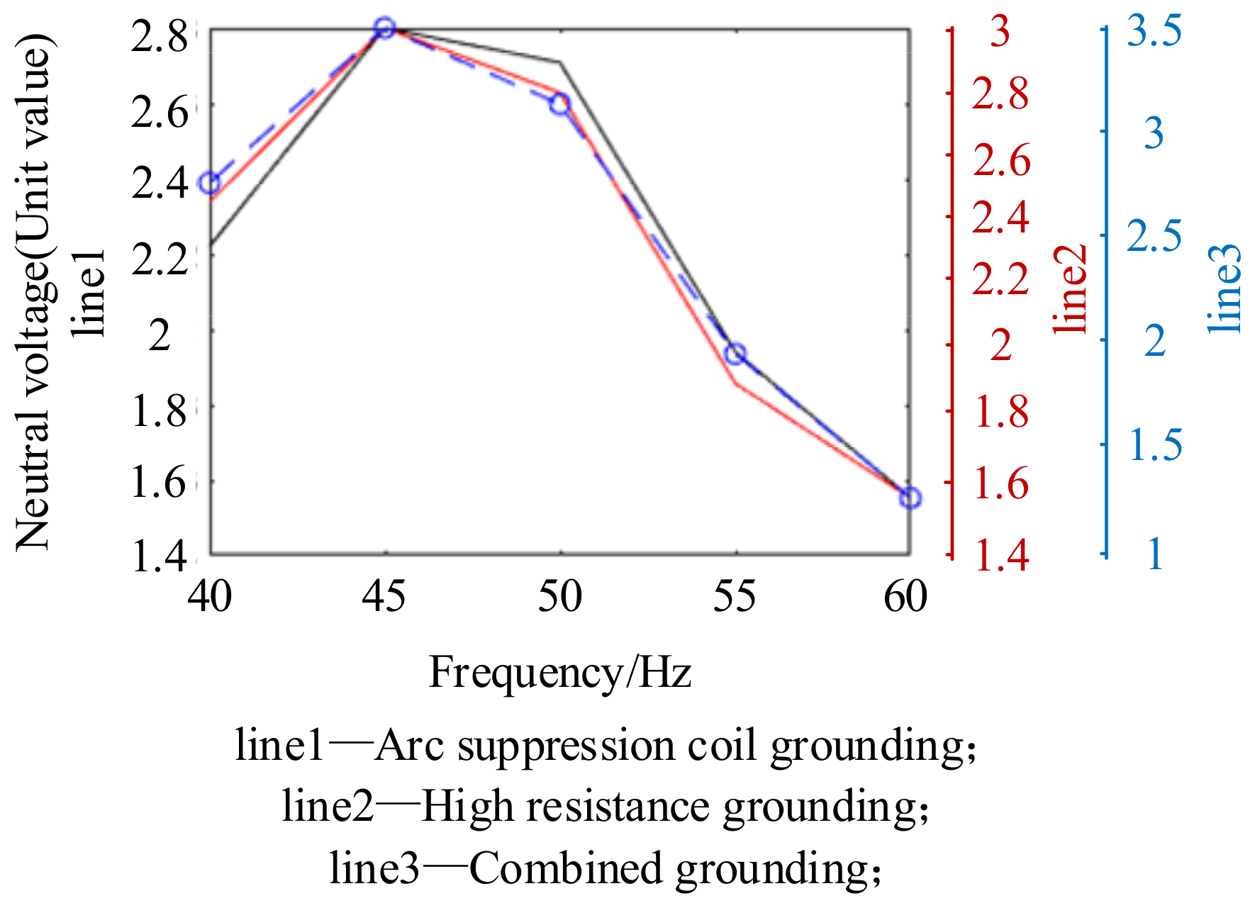
Table 2 that for three different neutral point grounding modes, when the stator winding single-phase grounding fault of hydro generator occurs, the increase or decrease of frequency will reduce the neutral point voltage drift. In order to further analyze the influence of frequency variation on neutral point drift, the simulation calculation of multiple frequency point changes was carried out, and the phase voltage of the generator was set as the reference value. In this way, the relationship curve between the transient unit value of neutral point voltage drift and frequency in case of single-phase grounding fault can be obtained, as shown in
Figure 9.
It can be seen from
Figure 9 that when a single-phase grounding fault occurs in the hydro generator, the influence trend of frequency variation on the neutral point voltage drift characteristics under three different neutral point grounding modes is the same. When the frequency is slightly less than the power frequency, the transient value of neutral point voltage drift can reach the maximum, and when the frequency is greater than the power frequency, the transient value of neutral point voltage drift tends to decrease.
Therefore, if the single-phase grounding fault of stator winding occurs when the frequency of the hydro generator is slightly less than the rated frequency, the voltage drift of neutral point will be more serious. Once this happens, it can be considered to take corresponding measures such as cutting off and de-excitation immediately to avoid endangering the safe and stable operation of the generator due to excessive voltage drift of neutral point.
4.3.3. Effect of Re-Arcing on Neutral Voltage Drift
Assuming that a secondary ground fault (reignition arc) occurs when the voltage returns to the maximum value, the dynamic characteristics of neutral point voltage drift after reignition arc are shown in
Figure 10.
It can be seen from
Figure 10 that for the combined neutral grounding mode, the re-arcing significantly increases the transient value of neutral voltage drift, while for arc suppression coil grounding and high-resistance grounding, the neutral point voltage is not higher than that of single arcing. The same method is used for multiple arcing simulation analysis, and the results are shown in
Table 3.
It can be seen from
Table 3 that for the third and fourth arcing, the difference between the transient value of neutral point voltage drift and the value of the second arcing is very small, and the probability of the third and fourth arcing is also very small.
5. Selection and Optimization of Neutral Grounding Device
According to the previous research results, the three grounding methods have advantages and disadvantages as follows:
The neutral point is grounded through the grounding transformer with high resistance, which cannot better limit the fault current and make it greatly exceed the specified value. The neutral point grounded through arc suppression coil has poor suppression characteristics for transient overvoltage, which may endanger the insulation safety. The combined grounding mode of neutral point can moderately restrain the grounding fault current and transient overvoltage, so that they do not exceed the safe range, but it will significantly improve the neutral point voltage drift, in which the transient value of neutral point voltage drift fault can reach twice the steady-state value.
For a 1000 MW hydro generator, from the perspective of safety, the combined neutral grounding mode should be preferred, but other methods should be used to suppress its voltage drift.
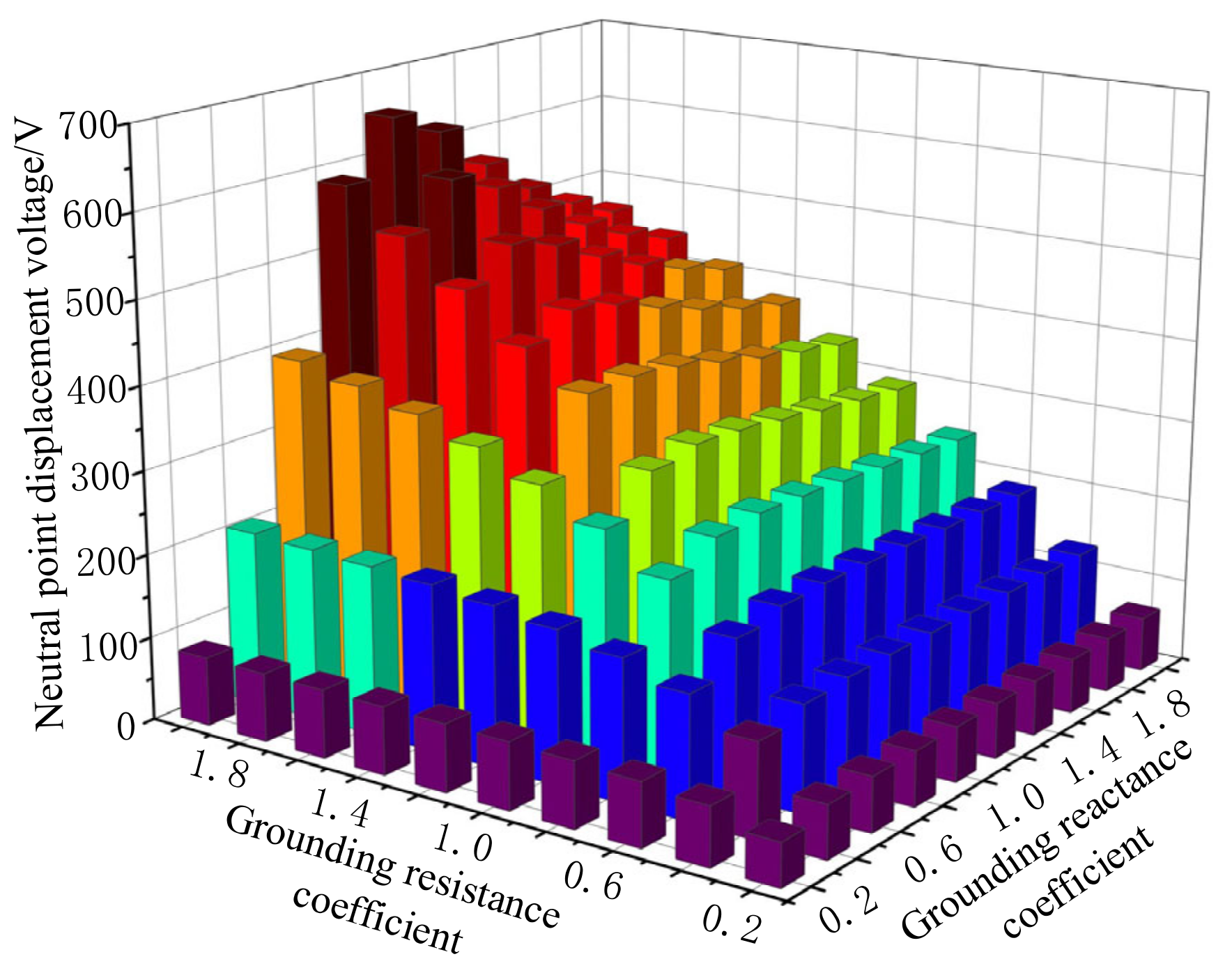
Figure 11 shows the influence of changing grounding parameters on neutral voltage drift under combined grounding mode. In the figure, the grounding resistance coefficient is defined as the ratio of the resistance in the neutral grounding device to the ground capacitive reactance of the stator winding, and the grounding reactance coefficient is the ratio of the reactance in the grounding device to the ground capacitive reactance of the stator winding. It can be seen that keeping the grounding reactance constant and appropriately reducing the grounding resistance coefficient can reduce the neutral point drift. Therefore, when using the combined grounding mode, the parameters of resistance and reactance should be reasonably selected.
6. Conclusions
Based on the asymmetry of three-phase parameters of hydro generator stator winding, this paper establishes the single-phase grounding fault model of hydro generator stator winding; analyzes and studies the fault current, transient overvoltage, and neutral point drift characteristics of a 1000 MW large hydro generator under a single-phase grounding fault of Baihetan Hydropower Station; and discusses the influence of frequency offset and re-arcing fault on neutral point voltage drift. Thus, the comprehensive variation law of fault parameters of a large hydro generator under single-phase grounding fault under different grounding modes is obtained.
For the super large hydro generator,
Although the high-resistance grounding mode can better suppress the transient overvoltage and neutral displacement voltage, it cannot meet the requirements of fault current limitation;
Although arc suppression coil grounding can better restrain the fault current to meet the specified value, it makes the transient overvoltage and neutral displacement voltage too high;
When the grounding parameters are reasonably selected, the combined grounding will cause the neutral point displacement voltage to rise, but it will not exceed the safety range, and can better suppress the fault current.
Therefore, for a 1000 MW hydro generator, the combined grounding mode of neutral point is more appropriate, but when selecting parameters, the grounding resistance coefficient should be appropriately reduced to restrain the neutral point voltage drift.
The above research results can provide reference for the selection of neutral grounding mode of a large hydro generator and research on generator protection.
Author Contributions
Conceptualization, B.X. and L.Z.; methodology, L.Z.; software, L.Z.; validation, B.X., L.Z. and S.D.; formal analysis, L.Z.; investigation, L.Z.; resources, B.X.; data curation, L.Z.; writing—original draft preparation, L.Z.; writing—review and editing, L.Z.; visualization, L.Z.; supervision, B.X.; project administration, S.D.; funding acquisition, B.X. All authors have read and agreed to the published version of the manuscript.
Funding
This research was funded by the National Natural Science Foundation of China, grant number 51977112; in part by the National Natural Science Foundation of Jiangsu Province, grant number BK20191370; and in part by the “Green and blue project” of Jiangsu (2019).
Institutional Review Board Statement
Not applicable.
Informed Consent Statement
Not applicable.
Conflicts of Interest
The authors declare no conflict of interest.
References
- Davarpanah, M.; Keravand, M.; Faiz, J.; Mousa-Haddadi, A.; Morsali, H.; Mahmoudi, A.; Amiri, A. Precise Locating of Stator Winding Earth Fault in Large Synchronous Generators. IEEE Trans. Ind. Appl. 2017, 53, 3137–3145. [Google Scholar] [CrossRef]
- Jaafari, K.A.; Toliyat, H.A. Performance Analysis of Synchronous Generators Under Stator Windings Ground Faults Near the Star Point-Experimental Verification. IEEE Trans. Energy Convers. 2020, 35, 1402–1410. [Google Scholar] [CrossRef]
- Wu, A.Y. MV Generator Ground Fault Arcing Power Damage Assessment. IEEE Trans. Ind. Appl. 2018, 54, 912–915. [Google Scholar] [CrossRef]
- Zhou, L.; Xiong, B.; Ding, S.Y. Influence factors of neutral point voltage drift and optimization analysis of grounding device parameters of 1000MW hydro generator. Adv. Technol. Electr. Eng. Energy 2022, 41, 59–66. [Google Scholar]
- Zhang, Q.X.; Zeng, X.J.; Xu, J. Analysis and discussion on combination-type grounding scheme for large-sized generator. Electr. Power Autom. Equip. 2018, 38, 317–322. [Google Scholar]
- Zeng, X.J.; Hu, J.Y.; Wang, Y. Suppressing method of three-phase unbalanced overvoltage based on distribution networks flexible grounding control. Proc. CSEE 2014, 34, 678–684. [Google Scholar]
- Xue, Y.D.; Li, J.; Xu, B.Y. Transient equivalent circuit and transient analysis of single-phase earth fault in arc suppression coil grounded system. Proc. CSEE 2015, 35, 5703–5714. [Google Scholar]
- Wang, B.; Cui, X. Nonlinear Modeling and Analytical Analysis of arc high resistance grounding fault in distribution network with neutral grounding via arc Suppression Coil. Proc. CSEE 2021, 41, 3864–3873. [Google Scholar]
- Brown, P.G.; Johnson, I.B.; Stevenson, J.R. Generator Neutral Grounding Some Aspects of Application for Distribution Transformer with Secondary Resistor and Resonant Types. IEEE Trans. Power Appar. Syst. 1978, PAS-97, 683–694. [Google Scholar] [CrossRef]
- Wang, Y.; Qian, G.J.; Wang, X.Y. Transient overvoltage of hydro generator with resonant grounding neutral. Power Syst. Technol. 2000, 24, 14–19. [Google Scholar]
- Li, R.L.; Li, Y.X.; Wang, X.H. The transient state research of generator stator neutral grounding schemes. Electr. Power Autom. Equip. 1999, 19, 1–5. [Google Scholar]
- Li, Y.X.; Wang, X.H.; Wang, W.J. A new approach for research of large generator stator neutral grounding schemes. Power Syst. Technol. 1997, 21, 15–18. [Google Scholar]
- Zhang, Q.X.; Wang, X.H.; Wang, W.J. Transient analysis on large hydro-generator with high resistance grounding. Power Syst. Technol. 2004, 28, 30–33, 37. [Google Scholar]
- Zhang, Q.X.; Wang, X.H.; Wang, W.J. Transient analysis on large hydro-generator with resonant neutral grounding. Autom. Electr. Power Syst. 2003, 27, 74–78. [Google Scholar]
- Fulczyk, M.; Bertsch, J. Ground-Fault Currents in Unit-Connected Generators with Different Elements Grounding Neutral. IEEE Trans. Energy Convers. 2002, 17, 61–66. [Google Scholar] [CrossRef]
- IEEE Std C37.101-2006 (Revision of IEEE Std C37.101-1993/Incorporates IEEE Std C37.101-2006/Cor1:2007); IEEE Guide for Generator Ground Protection. IEEE: Piscataway, NJ, USA, 2007; pp. 1–70. [CrossRef]
- IEEE Std C62.92.2-2017 (Revision of IEEE Std C62.92.2-1989); IEEE Guide for the Application of Neutral Grounding in Electrical Utility Systems, Part II–Synchronous Generator Systems. IEEE: Piscataway, NJ, USA, 2017; pp. 1–38. [CrossRef]
- Lin, X.; Tian, Q.; Gao, Y.; Liu, P. Studies on the Internal Fault Simulations of a High-Voltage Cable-Wound Generator. IEEE Trans. Energy Convers. 2007, 22, 240–249. [Google Scholar] [CrossRef]
- Bi, D.Q.; Wang, X.H.; Wang, W.J. Study on how to ground for the neutral point of large-sized hydro-generator. Trans. China Electrotech. Soc. 2002, 4, 7–12. [Google Scholar]
- Wang, W.J.; Gui, L.; Wang, X.H. Reconsideration and anxiety of neutral grounding mode for large generator. Electr. Equip. 2007, 11, 1–4. [Google Scholar]
- Xiong, Z.B.; Lu, W.; Guo, Z.X. Application of resonant compensation in neutral grounding mode of large generators. Power Syst. Clean Energy 2012, 28, 8–12. [Google Scholar]
- Zou, Z.B.; Chen, T. Research on Neutral Grounding Mode of 1000MW Hydro-generator. Water Power 2017, 43, 91–93. [Google Scholar]
| Publisher’s Note: MDPI stays neutral with regard to jurisdictional claims in published maps and institutional affiliations. |
© 2022 by the authors. Licensee MDPI, Basel, Switzerland. This article is an open access article distributed under the terms and conditions of the Creative Commons Attribution (CC BY) license (https://creativecommons.org/licenses/by/4.0/).


