Article

Dynamic Lane Tracking Control of the Commercial Vehicle Based on RMPC Algorithm Considering the State of Preceding Vehicle

Automotive Engineering Research Institute, Jiangsu University, Zhenjiang 212013, China
*
Author to whom correspondence should be addressed.
Machines 2022, 10(7), 534; https://doi.org/10.3390/machines10070534
Submission received: 6 June 2022 / Revised: 23 June 2022 / Accepted: 27 June 2022 / Published: 1 July 2022
(This article belongs to the Section Vehicle Engineering)

Abstract

:
In order to improve the adaptability of the lane keeping control system to complex environments, a dynamic lane tracking control strategy of the commercial vehicle based on the robust model predictive control (RMPC) algorithm is proposed considering the state of the preceding vehicle. An RMPC controller is designed with path deviation and control increment as the objective function. The model predictive control problem is transformed into a min–max optimization problem. The linear matrix inequality (LMI) is used for the optimal solution to obtain the optimal control quantity. The strategy to improve the safety and comfort dynamically in the process of lane keeping is designed by adjusting the weight coefficient matrix of RMPC based on fuzzy theory. The results of the simulation and HiL test show that the RMPC controller can meet the requirement of adjusting the lane tracking process dynamically according to the state of the preceding vehicle, which keeps the balance between safety and comfort.

1. Introduction

With the rapid development of the logistics industry, commercial vehicles as the main force of road transportation undertake the heavy logistics and freight tasks; thus, traffic accidents caused by driving fatigue occur frequently [1]. As an important part of the advanced assistant driving system (ADAS), a lane keeping system (LKS) controls the vehicle to drive in the target lane according to the road environment and vehicle state, which can effectively avoid traffic accidents caused by vehicle departure from the lane [2,3].
The lane keeping system makes decisions based on the vehicle state and environmental information obtained by the sensor of the perception layer, and manipulates the vehicle to drive along the lane [4]. As the core content of the lane keeping system, the lane keeping control algorithm can directly affect the control effect, which has been studied by many scholars [5]. The existing lane keeping control methods can be summarized into the following three types: deviation-based feedback control, model-based feedback control and end-to-end decision control [6,7,8]. Since the deviation-based feedback control does not consider the characteristics of the control system model, the control quantity often does not align with the actual situation, and it is not effective in dealing with high-order nonlinear problems. End-to-end decision control mostly uses reinforcement learning and deep learning methods, but due to the rigorous calculations, the advantages of engineering applications are not obvious. In contrast, model-based feedback control, combined with the model characteristics of the controlled system, can better solve the nonlinear feedback control problem of complex systems and carry out tracking control, which has become the research hotspots for many scholars [9,10]. Cai et al. put forward a lane keeping control method based on the extension switching theory by using double feedback control on the basis of a vehicle dynamic model and preview deviation model, which effectively suppressed the tracking errors under the condition of large curvature road conditions [11]. Considering that the lateral motion of the vehicle was affected by the uncertainty of the model and external interference, Swain et al. put forward a switching control strategy based on the higher order sliding mode (HOSM), and designed a radial basis function neural network (RBFNN) based on the robust lateral control method [12]. Aiming at the time delay of yaw angle speed in the process of lane keeping, Feng et al. introduced an adaptive time coefficient related to the road adhesion coefficient in the vehicle-road dynamic model and used the sliding mode control algorithm to track yaw rate [13]. Chen et al. designed a controller based on the sliding mode variable structure control (SM-VSC) method to decrease chattering and further improve lateral stability of the vehicle under extreme operating conditions; the adaptive power reaching law was realized by using a fuzzy control method [14]. Bai et al. applied nonlinear model predictive control (NMPC) into the path tracking control of a robot, took the discrete nonlinear error model as the nonlinear error of the prediction model, and used the feed-forward information of the reference path [15]. From the above literature, it can be found that model-based feedback control method largely depends on the accuracy of the system model, while the commercial vehicle has the characteristics of model uncertainty, time-varying behavior, strong nonlinearity of parameters and variable working environment. The above algorithms have limited ability to deal with the system’s uncertainty, and it is difficult to carry out lane keeping control well in the presence of external disturbances. Robust model predictive control (RMPC) combines the advantages of predictive control and robust control, which is an effective means to solve the poor robustness caused by model uncertainty and system disturbance [16]. Liu et al. designed a robust model predictive control (RMPC) controller for vehicles subjected to bounded model uncertainties, norm-bounded external disturbances and bounded time-varying delay. Simulation results showed that the proposed vehicle dynamic controller can steer vehicle states into a very small region near the reference tracking signal even in the presence of external disturbances, model uncertainties and time-varying delay [17]. Samuel et al. used model predictive control and proportional integral derivative control for lane keeping maneuvers of an autonomous vehicle. The simulation results showed that the optimizer made sure that the predicted future trajectory of the vehicle output tracked the desired reference trajectory [18]. Due to the differences in vehicle dynamics between real vehicles and this constant nominal model, Mata et al. introduced a tube-based RMPC method based on a simple linear and time invariant single track model. In addition, strict constraints were considered in the control signal and the lateral path tracking error [19].
Moreover, the preceding vehicle is also an important factor affecting the lane keeping control of commercial vehicles. Compared with passenger cars, due to the characteristics of a larger load and higher center of mass and longer wheelbase, commercial vehicles have longer adjustment time and distance during the process of lane keeping [20]. If the relative distance between the vehicle and the preceding vehicle is long and the relative speed is low, the driving condition of the vehicle is relatively safe, and the lane can be dynamically tracked and controlled smoothly. If the relative distance of two vehicles is short and the relative speed is fast, the vehicle needs to return to the lane centerline as soon as possible, so as to avoid the risk that the course of the vehicle cannot be adjusted immediately or even deviate from the lane during deceleration and collision avoidance [21,22]. Therefore, the relative distance, relative speed between the vehicle and the preceding vehicle and other state parameters will affect the safety and comfort in the process of lane keeping. Consequently, it is necessary to take the state of the preceding vehicle as the constraint for dynamic lane tracking control. However, the existing research does not consider the impact of external factors, including the state of preceding vehicle on dynamic lane tracking control, and the application scenario is relatively simple.
To sum up, this paper proposes a dynamic lane tracking control strategy based on the RMPC algorithm for commercial vehicles considering the state of the preceding vehicle. Firstly, a three degree of freedom vehicle model is built, which is linearized and discretized. Secondly, a robust model predictive controller is designed based on linear matrix inequality (linear matrix inequality, LMI) theory. Third, taking the state parameters of the preceding vehicle as the control input, the weight coefficient matrix in RMPC is adjusted based on the fuzzy control theory to dynamically track the lane, so as to give consideration to safety and comfort. Finally, the method is verified by simulation and HiL test. The results indicate that the proposed control strategy not only improves the robustness of the lane keeping control system, but also considers the influence of a complex driving environment, which is conducive to enhancing the environmental adaptability of the control system.

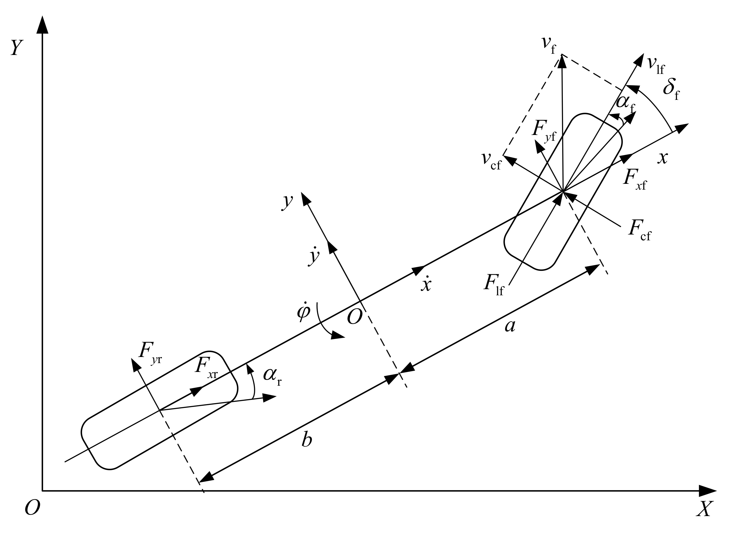
2. Vehicle Dynamics Model

In this paper, a three degree of freedom (3DOF) nonlinear vehicle dynamics model is established [23], as shown in Figure 1.
In this model, XOY is the inertial coordinate system, xoy is the vehicle coordinate system, and o represents the vehicle center of mass. According to Newton’s second law, the equations of vehicle dynamics are obtained in Equation (1).
m y ¨ = m x ˙ φ ˙ + 2 C cf δ f y ˙ + a φ ˙ x ˙ + C cr b φ ˙ y ˙ x ˙ m x ¨ = m y ˙ φ ˙ + 2 C lf s f + C cf δ f y ˙ + a φ ˙ x ˙ δ f + C lr s r I z φ ¨ = 2 a C cf δ f y ˙ + a φ ˙ x ˙ b C cr b φ ˙ y ˙ x ˙
where m is the vehicle mass, I z is the yaw inertia moment, φ is the yaw angle, φ ˙ is the yaw rate, a is the distance from the front axle to the center of mass, b is the distance from the rear axle to the center of mass, δ f is the front wheel angle, C cf , C cr are the cornering stiffness of front wheel and rear wheel, respectively and s f , s r are the slip ratio of front tire and rear tire, respectively.
The conversion relationship between the vehicle coordinate system and inertial coordinate system is as follows.
Y ˙ = x ˙ sin φ + y ˙ cos φ X ˙ = x ˙ cos φ y ˙ sin φ
For the convenience of research, Equations (1) and (2) are combined and written in the form of a state-space equation.
ξ ˙ = f ξ , u η = C ξ
The state variable is chosen as ξ = y ˙ , x ˙ , φ , φ ˙ , Y , X T , u = δ f is the control input variable and η = φ , Y T is the output variable. The coefficient matrix is selected as C = 0 0 1 0 0 0 0 0 0 0 1 0 .
Considering that the nonlinear continuous model cannot be directly used as a linear time-varying model for prediction, it is necessary to linearize and discretize the controlled model for the subsequent controller design, and the linear discrete state space expression is obtained as follows.
ξ k + 1 = A ξ k + B u k η k = C ξ k
The following equations can, therefore, be obtained:
A = f y ˙ y ˙ f y ˙ x ˙ 0 f y ˙ φ ˙ 0 0 f x ˙ y ˙ f x ˙ x ˙ 0 f x ˙ φ ˙ 0 0 0 0 0 1 0 0 f φ ˙ y ˙ f φ ˙ x ˙ 0 f φ ˙ φ ˙ 0 0 f Y y ˙ f Y x ˙ f Y φ 0 0 0 f X y ˙ f X x ˙ f X φ 0 0 0 , B = 2 C cf m 2 C cf 2 δ f y ˙ t + a φ ˙ t x ˙ t m 0 2 C cf a I z 00 T
These are in addition to the following equations:
f y ˙ y ˙ = 2 C cf + C cr m x ˙ , f x ˙ x ˙ = 2 C cf δ f y ˙ + a φ ˙ m x ˙ 2 , f y ˙ x ˙ = φ ˙ + C cf + C cr m x ˙ 2 y ˙ C cr b C cf a m x ˙ 2 φ ˙ , f y ˙ φ ˙ = x ˙ + 2 C cr b C cf a m x ˙ , f x ˙ y ˙ = φ ˙ 2 C cf δ f m x ˙ , f φ ˙ y ˙ = 2 C cr b C cf a I z x ˙ , f X φ = x ˙ sin φ y ˙ cos φ , f φ ˙ φ ˙ = 2 C cf a 2 + C cr b 2 I z x ˙ , f Y y ˙ = cos φ , f Y x ˙ = sin φ , f Y φ = x ˙ cos φ y ˙ sin φ , f X y ˙ = sin φ , f X x ˙ = cos φ , f φ ˙ x ˙ = C cr b C cf a I z x ˙ 2 y ˙ + C cf a 2 + C cr b 2 I z x ˙ 2 φ ˙ .

3. Dynamic Lane Tracking Control System

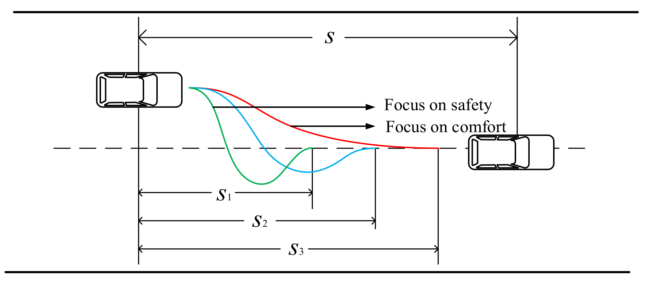
3.1. Dynamic Lane Tracking Control Strategy

In the process of dynamic lane tracking, the state parameters of the preceding vehicle, including the relative distance and relative speed, have a great impact on the control effect. As shown in Figure 2, if the relative distance between the vehicle and the preceding vehicle is small and the relative speed is large, the vehicle needs to quickly return to the lane centerline. When the distance between the vehicle and the preceding vehicle is less than the minimum safe distance, it is usual to avoid collision by braking and the vehicle speed decreases to a certain low value. If the deviation correction is not completed before emergency braking, the vehicle is at risk of departure from the lane, since the lane keeping function is disabled when the vehicle speed is less than 50 km/h. In this case, the dynamic lane tracking process focuses more on safety; the RMPC controller controls the vehicle to return to the lane centerline in a short time. If the relative distance between the vehicle and the preceding vehicle is large and the relative speed is small, the preceding vehicle has little influence on the dynamic lane tracking control, and the comfort is more important in the process of dynamic lane tracking. The RMPC controller should output a small and smooth front wheel angle to improve comfort.
The block diagram of the dynamic lane tracking control system is shown in Figure 3. In the RMPC controller, the objective function and constraints are obtained through the prediction model [24]. The given reference trajectory is the lane centerline under different working conditions. The optimal solution is carried out by using the linear matrix inequality (LMI) method [25], and the optimal front wheel angle is obtained and imposed on the vehicle. The state parameters of the preceding vehicle are the inputs of the fuzzy controller. The elements of ζ1, ζ2 in the variable weight coefficient matrix Q and the state parameters of the vehicle during the next time are input into the RMPC controller again. The continuous cycle constitutes the process of the dynamic lane tracking control based on the RMPC algorithm.

3.2. Design of LMI-Based RMPC Controller

The RMPC algorithm can deal with the problems of inaccurate model description or external disturbance, so as to effectively improve the stability [26]. There are many methods for the RMPC controller, among which min–max is a typical optimal control method. This method is mainly used to minimize the maximum value of the target function to obtain the best solution. LMI theory is used in this paper to solve the min–max optimization problem, and the dynamic lane tracking controller based on the LMI-based RMPC algorithm is designed [27].
(1) Objective function establishment
The key step of the controller design is objective function establishment. The optimal control sequence can be obtained only by solving the optimization problem according to the appropriate objective function. To ensure that the vehicle returns to the lane centerline quickly and steadily and to ensure the driving stability of the vehicle in the process of dynamic lane tracking, the objective function is established based on the path deviation and the control quantity. The optimal control sequence may not be obtained in the process of the optimization solution of the objective function due to the time-varying model, so the objective function needs to add a relaxation factor so that the controller can obtain the best solution [28]. The objective function is presented as Equation (5).
J k = i = 1 N p η k + i | k η r e f k + i | k Q 2 + i = 1 N c 1 u k + i 1 | k R 2 + ρ ε 2
where N p is the prediction horizon, N c is the control horizon, Q = d i a g ζ 1 , ζ 2 is the output quantity weight coefficient matrix, R is the control quantity coefficient weight matrix, ρ is the weight coefficient; ε is the relaxation parameters.
In Equation (5), the first part represents the tracking performance of the desired trajectory and the second part is to reflect the safety performance. However, it is difficult to guarantee the variation in control quantity in each control time-domain only when the control quantity is added into the objective function. In order to prevent the sudden change in control quantity in different control time-domains, the control increment instead of the control quantity is used as the state variable. The objective function is rewritten as follows.
J k = i = 1 N p η k + i | k η r e f k + i | k Q 2 + i = 1 N c 1 Δ u k + i | k R 2 + ρ ε 2
To solve the objective function shown as Equation (6), the new state variable is set as ξ ˜ k = ξ k u k 1 , and Equation (4) is transformed as follows.
ξ ˜ k + 1 = A ˜ ξ ˜ k + B ˜ Δ u k η ˜ k = C ˜ ξ ˜ k
The following equation can, therefore, be obtained:
A ˜ = A B 0 1 × 6 I 1 × 1 , B ˜ = B I 1 × 1 , Δ u k = u k u k 1 , C ˜ = C 0 2 × 1
According to the discrete vehicle dynamics model, the output of the prediction model in steps at time can be obtained by Equation (8).
Y k = Ψ k ξ ˜ k + Θ k Δ U k
In addition, the following equations can, therefore, be obtained:
Y k = η ˜ k + 1 | k η ˜ k + 2 | k η ˜ k + N c | k η ˜ k + N p | k , Ψ k = C ˜ A ˜ C ˜ A ˜ 2 C ˜ A ˜ N c C ˜ A ˜ N p T Θ k = C ˜ B ˜ 0 0 0 C ˜ A ˜ B ˜ C ˜ B ˜ 0 0 C ˜ A ˜ N c 1 B ˜ C ˜ A ˜ N c 2 B ˜ C ˜ B ˜ C ˜ A ˜ N c B ˜ C ˜ A ˜ N c 1 B ˜ C ˜ A ˜ B ˜ C ˜ A ˜ N p 1 B ˜ C ˜ A ˜ N p 2 B ˜ C ˜ A ˜ N p N c 1 B ˜ , Δ U k = Δ u k | k Δ u k + 1 | k Δ u k + N c | k
(2) Constraint condition setting
In the process of controller design, it is also important to establish the appropriate constraints in addition to the appropriate objective function. In order to ensure the driving safety and comfort of the vehicle and avoid the instability of the vehicle, the control quantity, control increment and output are constrained as follows.
u min k + j u k + j u max k + j j = 0 , 1 , , N c 1 η min k + j η k + j η max k + j j = 0 , 1 , , N p Δ u min k + j Δ u k + j Δ u max k + j j = 0 , 1 , , N c 1
(3) RMPC optimization solution
Combining the above objective functions and constraints, the min objective function optimization problem in each sampling period is transformed into the following min–max form [29].
min u ( k + i ) max A k + i , B k + 1 Ω , i 0 i = 1 N p η k + i | k η r e f k + i | k Q 2 + i = 1 N c 1 Δ u k + i | k R 2 + ρ ε 2
s.t.
u min k + j u k + j u max k + j Δ u min k + j Δ u k + j Δ u max k + j y min k + j y k + j y max k + j ε > 0
Due to the complexity of the direct optimization calculation process of the objective function, the predictive control optimization problem is converted into linear matrix inequality problem.
One can construct a quadratic function V x = x T P x , P 0 , assuming that V satisfies the following inequality.
V η k + i + 1 k V η k + i k σ 1 + σ 2
The following equations can, therefore, be obtained:
σ 1 = η k + i k T Q η k + i k , σ 2 = u k + i k T R u k + i k
Considering that the robustness index is limited, in the case of terminal zero state, η k = 0 , and V η k = 0 .
The sum of above formulas is shown in Equation (12).
V η k k J k
Therefore, Equation (13) can be obtained.
max A k + i , B k + 1 Ω , i 0 J k V η k k
It can be observed from Equation (13) that the upper bound of robustness index is V η k k . An optimal state feedback control law u k + i k = K η k + i k needs to be obtained, in which the state feedback control matrix K = G P 0 1 , P 0 = γ P 1 . J ( k ) reaches the minimum by minimizing the upper bound V η k k ; Equation (14) can be obtained [30].
max A k + i , B k + 1 Ω , i 0 J k + ε 0 T W ε 0 V η k k + ε 0 T W ε 0 γ
where ε 0 is the softening factor.
Considering u k + i k = K η k + i k , the state space expression can be reconstructed as Equation (15),
η k + i + 1 k = A k + i + B k + i K η k + i k .
Substituting V η k k = η k k T P η k k into Equation (11), Equation (16) can be obtained.
σ 4 σ 3 σ 1 + σ 2
The following equations can be, therefore, obtained: σ 3 = η k + i k T P η k + i k , σ 4 = η k + i + 1 k T P η k + i + 1 k .
Substituting Equation (15) into Equation (16), (17) is obtained as follows.
η k + i k T μ T P μ P + Q + K T R K η k + i k 0
The following equation can be obtained: μ = A k + i + B k + i K .
Equation (17) can be simplified to Equation (18).
μ T P μ P + Q + K T R K 0
According to Schur complement theorem, Equation (18) can be written as
P 0 G T P 0 P 0 A T + G T B T G γ R 0 0 P 0 0 γ Q 0 A P 0 + B G 0 0 P 0 0
Substituting V η k k = η k k T P η k k into Equation (15), Equation (20) can be obtained.
η k k T P η k k + ε 0 T W ε 0 γ 0
According to Schur complement theorem, Equation (20) is equivalent to the following formula.
1 η k k T ε 0 T η k k P 0 0 ε 0 0 γ W - 1 0
To sum up, if Equation (19) could be solved under the condition that Equation (21) is satisfied, there would be a state feedback control law that u k + i k = K η k + i k to minimize V x k k .

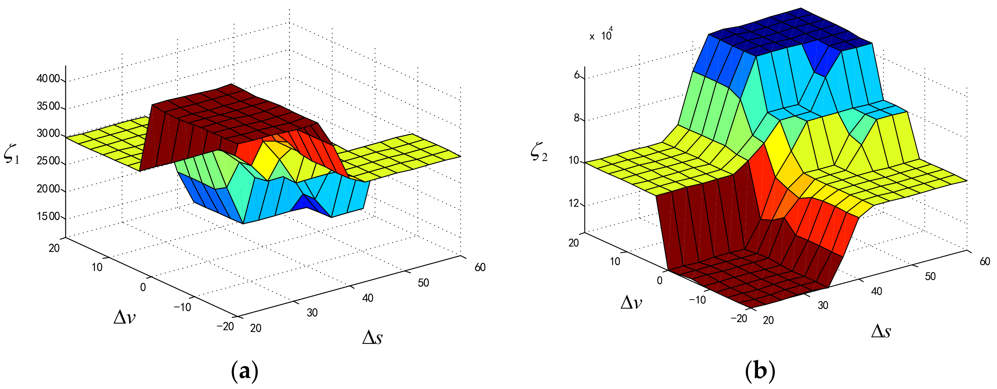
3.3. Design of the Variable Weight Coefficient Matrix of RMPC Based on Fuzzy Theory

It is assumed that the weight coefficient R remains constant in the RMPC objective function. By adjusting the elements of ζ1 ζ2 in the variable weight coefficient matrix Q based on fuzzy theory, the real-time dynamic adjustment of the lane tracking is implemented according to the state parameters of the local vehicle and the preceding vehicle [31,32].
The relative distance Δ s and relative speed Δ v between the vehicle and the preceding vehicle are inputs of the fuzzy controller, which outputs the matrix elements ζ1 ζ2.The fuzzy sets corresponding to the relative distance Δ s are {NB (negative large), NS (negative small), ZO (zero), PS (positive small), PB (positive large)}, and the fuzzy universe is (20,60). The fuzzy sets related to the relative speed Δ v are {NB (negative large), NS (negative small), ZO (zero), PS (positive small), PB (positive large)}, and the fuzzy universe is (–20,20). The fuzzy subset of ζ1 ζ2 are {ZO (zero), PS (positive small), PM (center), PB (positive large)}.
Three fuzzy rules are designed as follows.
(a) When the relative distance Δ s between the vehicle and the preceding vehicle is very small, the driving condition is dangerous. The elements of ζ1 ζ2 in the variable weight coefficient matrix Q are increased according to the relative speed Δ v . In other words, if the fuzzy universe of Δ v changes from NB to PB, ζ1 ζ2 change from PB to PM, correspondingly.
(b) When the fuzzy universe of Δ s is in ZO, the relative distance between the two vehicles is moderate. In this case, when Δ v is in the fuzzy universe of NB-ZO, the safety and comfort of vehicles need to be considered simultaneously; when Δ v is in PS-PB, vehicle driving comfort should be paid more attention. In short, if the universe of Δ v changes from NB to PB, ζ1 ζ2 change from PM to ZO, accordingly.
(c) When Δ s is large and set in PS-PB, the distance between two vehicles is namely in a safe distance; it is necessary to attach importance to the comfort of vehicle driving. In this situation, when the universe of Δ v changes from NB to PB, ζ1 ζ2 change from PM to ZO.
Fuzzy control rules in detail are presented in Table 1. The input–output relationship of the fuzzy controller is shown in Figure 4.

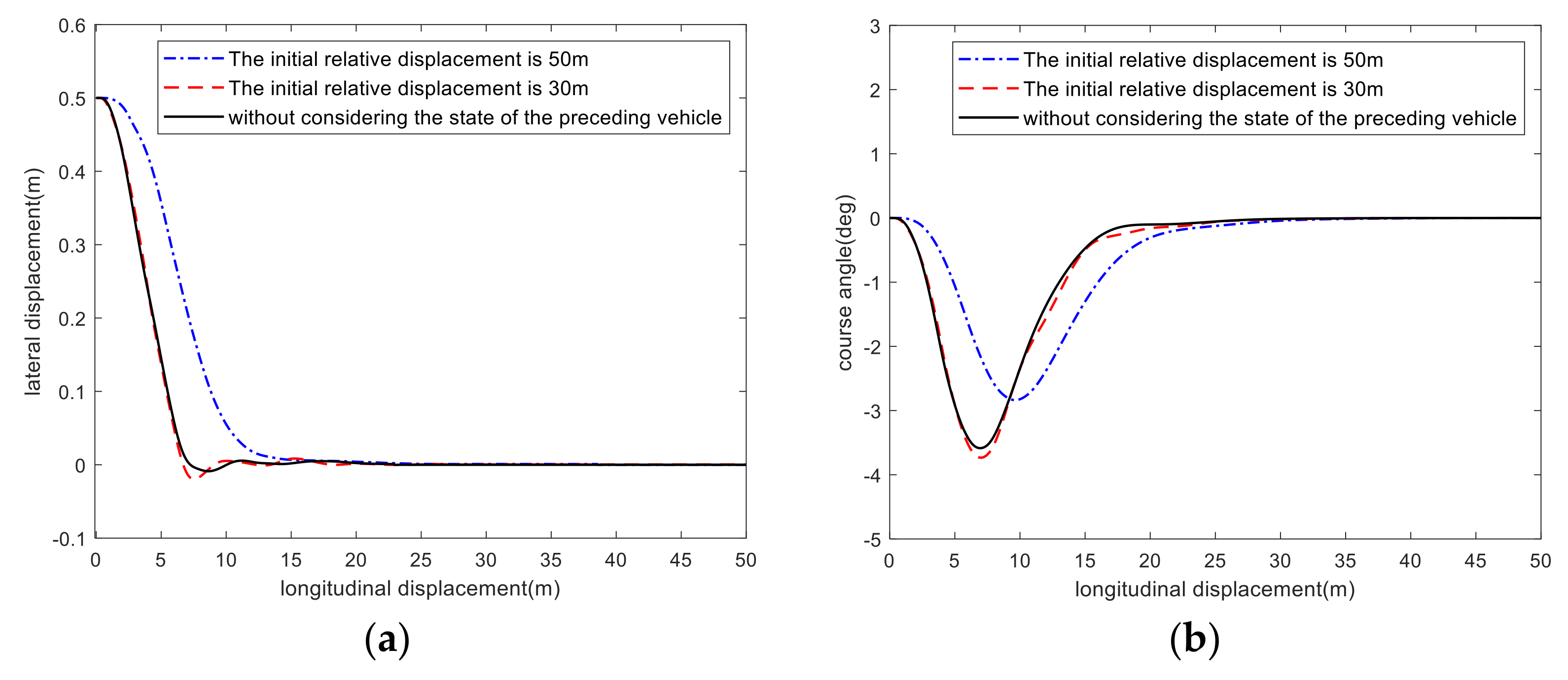
4. Simulation Verification and Result Analysis

To evaluate the performance of the dynamic lane tracking control strategy considering the state of the preceding vehicle in this paper, the vehicle model and road model are established on the Trucksim-Simulink platform, and the controller algorithm is compiled in MATLAB for co-simulation. The prediction horizon Np = 25, control horizon Nc = 12; the sampling time T = 0.02 s. The vehicle parameters are shown in Table 2. The simulation is conducted under the straight road condition at the speed of 40 km/h. Case 1 is as follows: initial relative distance between the local vehicle and the preceding vehicle is set as 30 m, and the initial relative speed is set as 15 km/h. Case 2 is as follows: initial relative distance is set as 50 m, and the initial relative speed is set as 5 km/h. The comparison of the simulation results is shown in Figure 5.
From Figure 5a, it can be observed that when the initial relative distance is 30 m, the response time of the vehicle for lane tracking is the shortest, and the response speed is 7.8% faster than that of the RMPC controller, without considering the state of the preceding vehicle. However, in Figure 5c, its yaw rate is larger, which indicates that when the distance between two vehicles is small, the primary goal of the vehicle is to complete lane tracking as soon as possible to ensure safety. In this case, the vehicle has better lane tracking performance, faster response speed and poor comfort. When the initial relative distance between the two vehicles is set as 50 m, Figure 5a shows that the response time of the vehicle for lane tracking is longer, and the response speed of the RMPC controller considering the preceding vehicle state is 59.4% lower than that of the RMPC controller without considering the preceding vehicle state. In this case, as shown in Figure 5c, the yaw rate is still small, which indicates that when the local vehicle is far from the preceding vehicle, the primary goal of lane tracking control is to ensure both comfort and safety. In this situation, the comfort of the vehicle is higher, and the lane tracking performance and accuracy are slightly worse.
In order to further verify the effectiveness of the RMPC controller considering the state of preceding vehicle at medium-high speed, a simulation is conducted under straight road conditions at the speed of 80 km/h. The comparisons of simulation results are shown in Figure 6.
From the figures, when the initial relative distance between two vehicles is set as 30 m, the response speed of the RMPC controller considering the state of preceding vehicle is 6.8% faster than that without considering the preceding vehicle state, while when the initial relative distance is set as 50 m, the response speed of the RMPC controller considering the state of preceding vehicle is 57.2% slower than that without considering the preceding vehicle state. Compared with 50 km/h, the lane tracking error, course angle, and yaw rate at 80 km/h is larger so that a slight steering wheel angle can bring about a larger state change in the vehicle at high speed. However, the vehicle is still in the safe state.
To sum up, the adaptability of the RMPC controller considering the state of preceding vehicle is better than that of the RMPC controller without considering the preceding vehicle state, whether it is at low speed or medium-high speed. The driving safety and comfort during dynamic lane tracking can be achieved by adjusting the variable weight coefficients matrix according to the relative distance and relative speed of two vehicles.

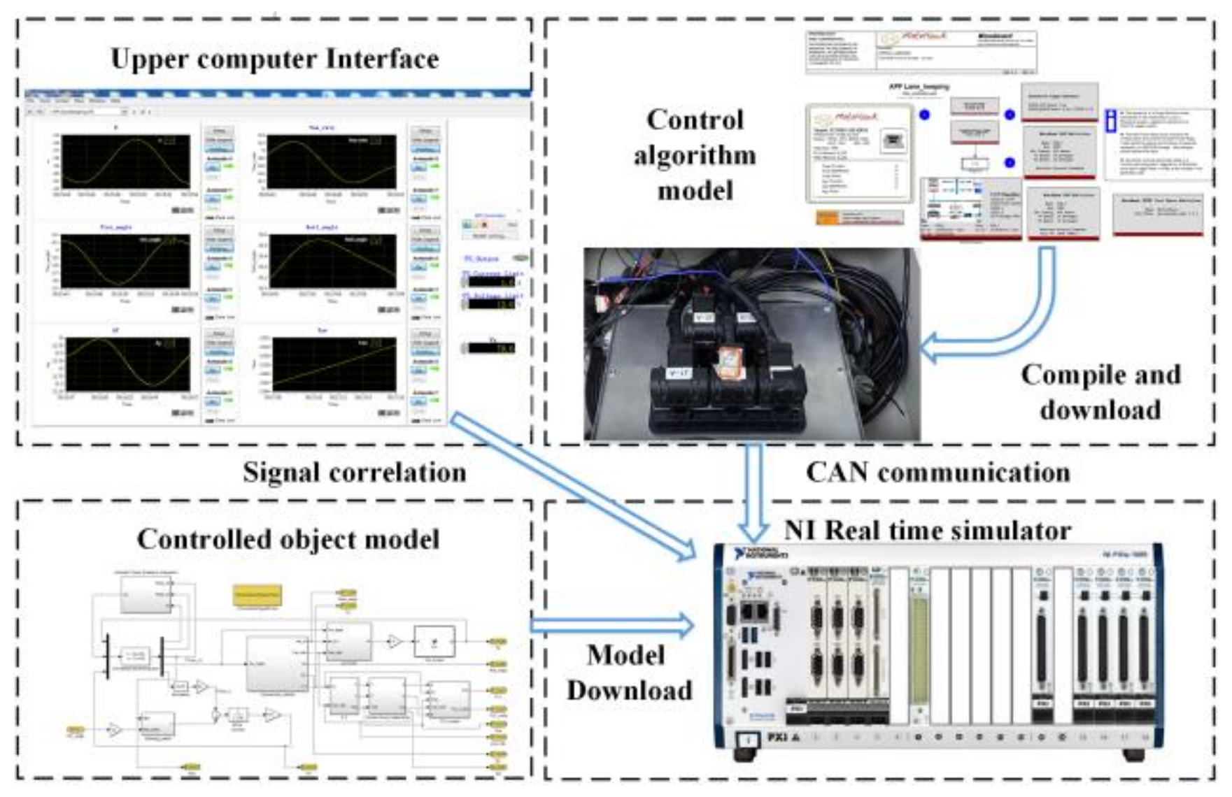
5. Hardware-in-the-Loop Test

In order to verify the effectiveness of the dynamic lane tracking control algorithm in the real controller, the HiL (hardware-in-the-loop) test was carried out. The HiL test platform is shown in Figure 7, including the host computer, the simulator and D2P controller. The software system of the HiL test platform mainly includes the controlled object model, control algorithm and host computer system configuration. The controlled object model is compiled in MATLAB and transferred to the simulator by the host computer software. The control algorithm is compiled and downloaded to the D2P controller. The digital signal output from the controlled object model in the simulator is transferred to the D2P controller. Under the calculation and processing of the control algorithm, the control signal is transmitted to the controlled object model through the communication card, which forms a closed-loop control. The overall test block diagram is shown in Figure 8.
The test is under the straight road conditions with an initial relative distance of 30 m at a speed of 40 km/h and 80 km/h. The HiL test results are shown in Figure 9 and Figure 10.
From Figure 9a–c, it can be observed that the tracking accuracy of HiL test is slightly lower than that of co-simulation. Nevertheless, it is able to track the lane centerline well and tends to be stable. Figure 9a shows that the maximum path tracking error of HIL test and co-simulation is 0.04 m, and the tendency of the path tracking is basically consistent. In Figure 9b,c, the errors of course angle and yaw rate are generally within a reasonable range. The comparison results verify the feasibility of the control strategy designed in this paper under medium-low speed conditions.
Figure 10 shows the comparisons of co-simulation and HiL test results at the speed of 80 km/h. It can be observed from Figure 10a that the maximum path tracking error of the HiL test and co-simulation is always within an acceptable range of 0.04 m at high speed. From Figure 10b,c, it can be observed that the trend of course angle and yaw rate of the HiL test is basically consistent with that of the co-simulation, which indicates that the control strategy designed in this paper has a good control effect under high speed conditions.

6. Conclusions

The lane dynamic tracking control algorithm considering the state of the preceding vehicle is proposed for the lane keeping system in commercial vehicles to achieve better environmental adaptation and robustness. The main conclusions are drawn as follows.
(1)
The 3-DOF vehicle dynamics model of commercial vehicles is established, and the dynamic lane tracking controller based on RMPC is designed. The model predictive control problem is transformed into a ‘min–max’ problem by using LMI theory, which solves the robustness problem caused by model uncertainty and external interference.
(2)
A dynamic lane tracking control strategy considering the state of the preceding vehicle is proposed. According to the relative distance, relative speed between the local vehicle and the preceding vehicle, the variable weight coefficients matrix is dynamically adjusted by a fuzzy controller to meet the requirements of safety and comfort in the process of dynamic lane tracking, according to the state of the preceding vehicle.
(3)
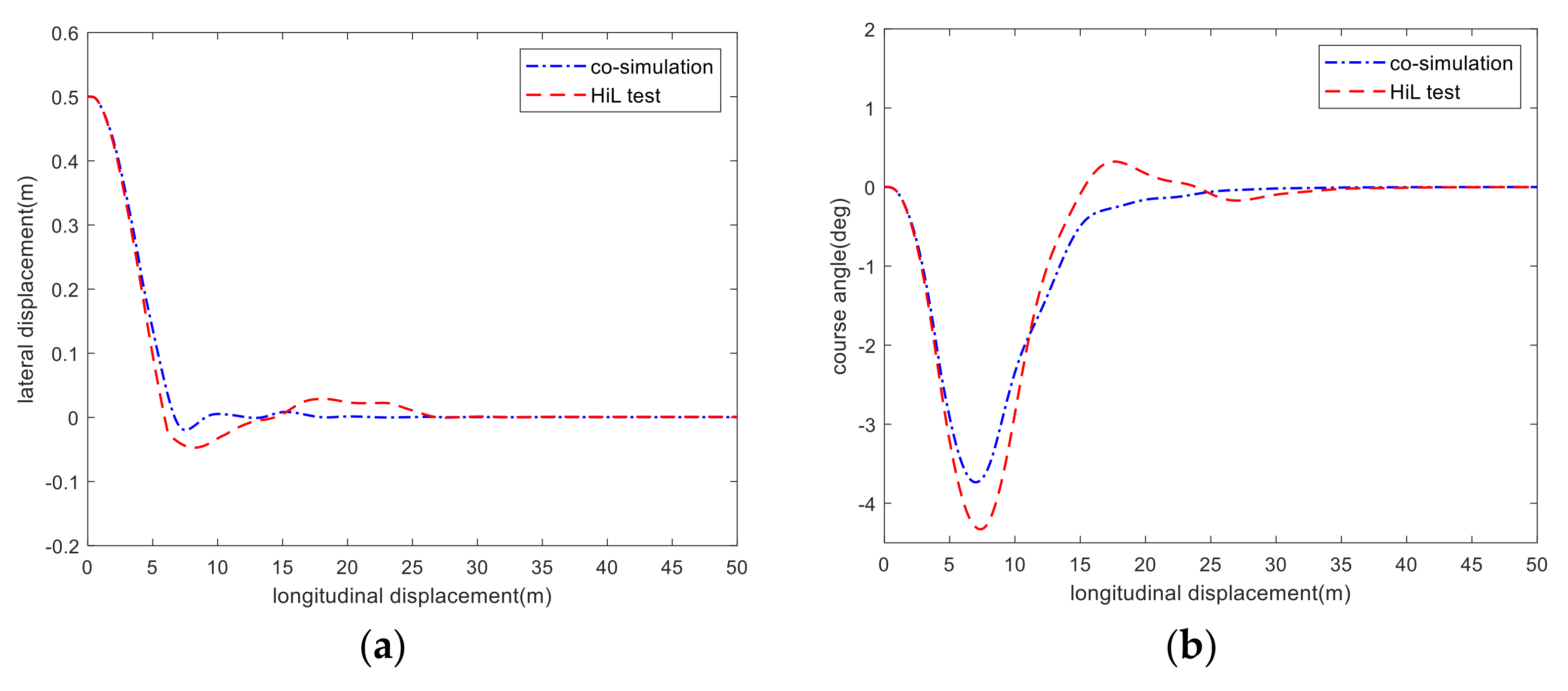
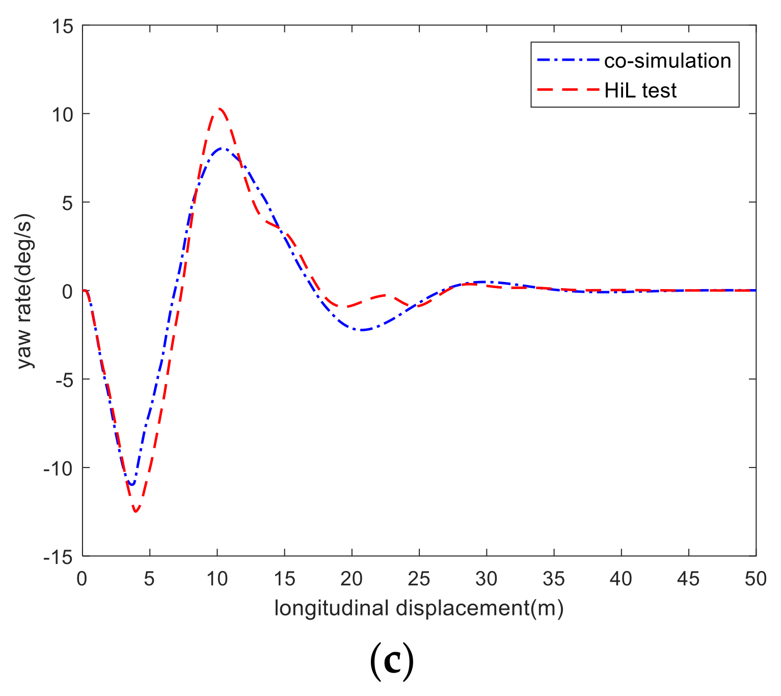
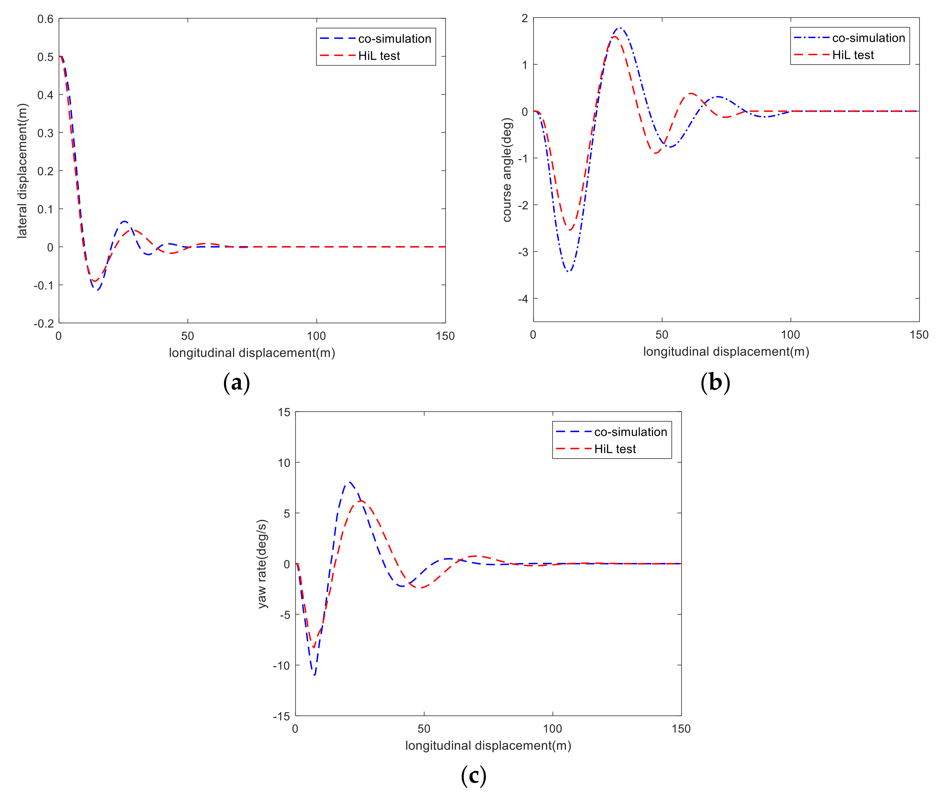
The results of the co-simulation and HiL test show that the RMPC controller considering the state of preceding vehicle enhances the response speed of lane tracking when the relative distance is short and improves the comfort in the process of lane tracking when the relative distance is long, which demonstrates that the RMPC controller considering the state of preceding vehicle has better environmental adaptability.
(4)
The relative distance and relative speed of the preceding vehicle are only considered in this paper. More environmental factors that affect the vehicle’s lane tracking need to be further taken into account to deal with more complex driving scenes, and the robustness and adaptability of the control algorithm can be verified by real vehicle experiments.

Author Contributions

Conceptualization, B.T. and Y.Y.; methodology, B.T. and Y.Y.; software, Z.H. and Z.Y.; validation, Z.H. and Z.Y.; investigation, Y.Y.; data curation, Z.Y.; writing—original draft preparation, Y.Y.; writing—review and editing, B.T. and Z.H.; visualization, Y.Y.; supervision, H.J.; funding acquisition, B.T. All authors have read and agreed to the published version of the manuscript.

Funding

This work was supported in part by the National Natural Science Foundation of China (Grant No. 51605199), Key Research and Development Projects of Jiangsu Province (Grant No. BE2019010), Six Talent Peaks Project in Jiangsu Province (Grant No.2019-GDZB-084).

Conflicts of Interest

The authors declared no potential conflicts of interest with respect to the research, authorship, and/or publication of this article.

References

  1. Kvári, B.; Hegedüs, F. Bécsi, T Design of a reinforcement learning-based lane keeping planning agent for automated vehicles. Appl. Sci. 2020, 10, 7171. [Google Scholar] [CrossRef]
  2. Hu, C.; Qin, Y.; Cao, H.; Song, X.; Jiang, K.; Rath, J.J.; Wei, C. Lane keeping of autonomous vehicles based on differential steering with adaptive multivariable super-twisting control. Mech. Syst. Signal Process. 2019, 125, 330–346. [Google Scholar] [CrossRef]
  3. Lee, J.; Choi, J.; Yi, K.; Shin, M.; Ko, B. Lane-keeping assistance control algorithm using differential braking to prevent unintended lane departures. Control. Eng. Pract. 2014, 23, 1–13. [Google Scholar] [CrossRef]
  4. Taghavifar, H.; Hu, C.; Taghavifar, L.; Qin, Y.; Na, J.; Wei, C. Optimal robust control of vehicle lateral stability using damped least-square backpropagation training of neural networks. Neurocomputing 2020, 384, 256–267. [Google Scholar] [CrossRef]
  5. Liu, M.; Deng, X.; Lei, Z.; Jiang, C.; Piao, C. Autonomous lane keeping system: Lane detection, tracking and control on embedded system. J. Electr. Eng. Technol. 2020, 16, 569–578. [Google Scholar] [CrossRef]
  6. Lin, F.; Wang, S.; Zhao, Y.; Cai, Y. Research on autonomous vehicle path tracking control considering roll stability. Proc. Inst. Mech. Eng. Part D J. Automob. Eng. 2020, 235, 199–210. [Google Scholar] [CrossRef]
  7. Dang, T.S.; Duong, D.T.; Le, V.C.; Banerjee, S. A combined backstepping and adaptive fuzzy PID approach for trajectory tracking of autonomous mobile robots. J. Braz. Soc. Mech. Sci. Eng. 2021, 43, 156. [Google Scholar] [CrossRef]
  8. Chen, Z.L.; Li, L.N.; Huang, X.M. Building an autonomous lane keeping simulator using real-world data and end-to-end learning. IEEE Intell. Transp. Syst. Mag. 2018, 12, 47–59. [Google Scholar] [CrossRef]
  9. Choi, M.; Choi, S.B. MPC for vehicle lateral stability via differential braking and active front steering considering practical aspects. Proc. Inst. Mech. Eng. Part D J. Automob. Eng. 2016, 230, 459–469. [Google Scholar] [CrossRef]
  10. Cheng, S.; Li, L.; Liu, Y.G.; Li, W.B.; Guo, H.Q. Virtual fluid-flow-model-based lane-keeping integrated with collision avoidance control system design for autonomous vehicles. IEEE Trans. Intell. Transp. Syst. 2021, 22, 6232–6241. [Google Scholar] [CrossRef]
  11. Cai, Y.F.; Zang, Y.; Sun, X.Q.; Chen, X.B.; Chen, L. Lane-keeping system of intelligent vehicles based on extension switching control method. China, J. Highw. Transp. 2019, 32, 43–52. [Google Scholar] [CrossRef]
  12. Swain, S.K.; Rath, J.J.; Veluvolu, K.C. Neural network based robust lateral control for an autonomous vehicle. Electronics 2021, 10, 510. [Google Scholar] [CrossRef]
  13. Feng, P.F.; Jin, H.Q.; Wang, H.R.; Liu, F. Lane keeping control by considering influences of road adhesion and adaptive time coefficients. China Mech. Eng. 2020, 33, 156–166. [Google Scholar] [CrossRef]
  14. Chen, W.; Zhang, R.; Zhao, L.; Wang, H.; Wei, Z. Control of chaos in vehicle lateral motion using the sliding mode variable structure control. Proc. Inst. Mech. Eng. Part D J. Automob. Eng. 2019, 233, 776–789. [Google Scholar] [CrossRef]
  15. Bai, G.; Meng, Y.; Liu, L.; Luo, W.; Gu, Q.; Liu, L. Review and comparison of path tracking based on model predictive control. Electronics 2019, 8, 1077. [Google Scholar] [CrossRef] [Green Version]
  16. Peng, H.; Wang, W.; An, Q.; Xiang, C.; Li, L. Path tracking and direct yaw moment coordinated control based on robust MPC with the finite time horizon for autonomous independent-drive vehicles. IEEE Trans. Veh. Technol. 2020, 69, 6053–6066. [Google Scholar] [CrossRef]
  17. Liu, W.; Chen, G.; Knoll, A. Matrix inequalities based robust model predictive control for vehicle considering model uncertainties, external disturbances, and time-varying delay. Front. Neurorobotics 2021, 14, 110. [Google Scholar] [CrossRef]
  18. Samuel, M.; Mohamad, M.; Hussein, M.; Saad, S.M. Lane keeping maneuvers using proportional integral derivative (PID) and model predictive control (MPC). J. Robot. Control. 2021, 2, 78–82. [Google Scholar] [CrossRef]
  19. Mata, S.; Zubizarreta, A.; Pinto, C. Robust tube-based model predictive control for lateral path tracking. IEEE Trans. Intell. Veh. 2019, 4, 569–577. [Google Scholar] [CrossRef]
  20. Zhao, W.Z.; Luan, Z.K.; Wang, C.Y. Parameter optimization design of vehicle E-HHPS system based on an improved MOPSO algorithm. Adv. Eng. Softw. 2018, 123, 51–61. [Google Scholar] [CrossRef]
  21. Park, D.; Her, H.; Yi, K. Development of roll stability control of commercial vehicles with environment information. J. Auto-Veh. Saf. Assoc. 2013, 5, 50–55. [Google Scholar] [CrossRef]
  22. Son, Y.S.; Kim, W.; Lee, S.H.; Chung, C.C. Robust multirate control scheme with predictive virtual lanes for lane-keeping system of autonomous highway driving. IEEE Trans. Veh. Technol. 2014, 64, 3378–3391. [Google Scholar] [CrossRef]
  23. Marumo, Y.; Yokota, T.; Aoki, A. Improving stability and lane-keeping performance for multi-articulated vehicles using vector follower control. Veh. Syst. Dyn. 2020, 58, 1859–1872. [Google Scholar] [CrossRef]
  24. Fesharaki, S.J.; Kamali, M.; Sheikholeslam, F.; Talebi, H.A. Robust model predictive control with sliding mode for constrained non-linear systems. IET Control. Theory Appl. 2020, 14, 2592–2599. [Google Scholar] [CrossRef]
  25. Moradi, S.M.; Ahmad, A.; Mehdi, M. An offline LMI-based robust model predictive control of vehicle active suspension system with parameter uncertainty. Trans. Inst. Meas. Control. 2019, 41, 1699–1711. [Google Scholar] [CrossRef]
  26. Xie, H.; Dai, L.; Luo, Y.; Xia, Y. Robust MPC for disturbed nonlinear discrete-time systems via a composite self-triggered scheme. Automatica 2021, 127, 109499. [Google Scholar] [CrossRef]
  27. Salvati, L.; d’Amore, M.; Fiorentino, A.; Pellegrino, A.; Sena, P.; Villecco, F. Development and testing of a methodology for the assessment of acceptability of LKA systems. Machines 2020, 8, 47. [Google Scholar] [CrossRef]
  28. Bououden, S.; Chadli, M.; Karimi, H.R. A robust predictive control design for nonlinear active suspension systems. Asian, J. Control. 2016, 18, 122–132. [Google Scholar] [CrossRef]
  29. Bouzid, A.E.M.; Chaoui, H.; Zerrougui, M.; Elghali, S.B.; Benbouzid, M. Robust control based on linear matrix inequalities criterion of single phase distributed electrical energy systems operating in islanded and grid-connected modes. Appl. Energy 2021, 292, 116776. [Google Scholar] [CrossRef]
  30. Yang, L.; Yue, M.; Wang, J.; Hou, W. RMPC-based directional stability control for electric vehicles subject to tire blowout on curved expressway. J. Dyn. Syst. Meas. Control. 2019, 141, 041009. [Google Scholar] [CrossRef]
  31. He, J.; McCarley, J.S.; Kramer, A.F. Lane keeping under cognitive load: Performance changes and mechanisms. Hum. Factors 2014, 56, 414–426. [Google Scholar] [CrossRef] [PubMed]
  32. Lin, F.; Chen, Y.; Zhao, Y.; Wang, S. Path tracking of autonomous vehicle based on adaptive model predictive control. Int. J. Adv. Robot. Syst. 2019, 16, 1729881419880089. [Google Scholar] [CrossRef]
Figure 1. Vehicle dynamics model.
Machines 10 00534 g001
Figure 2. Diagram of dynamic lane tracking process considering the state of preceding vehicle. S1 is the longitudinal distance of the vehicle back to the centerline when safety is concerned; S2 is the longitudinal distance of the vehicle back to the centerline under normal conditions; S3 is the longitudinal distance of the vehicle back to the centerline when comfort is concerned.
Machines 10 00534 g002
Figure 3. Block diagram of dynamic lane tracking control system.
Machines 10 00534 g003
Figure 4. Relationship between input and output of fuzzy controller. (a) Surface graph of ζ1 (b) Surface graph of ζ2.
Machines 10 00534 g004
Figure 5. Comparisons between Case 1 and Case 2 at the speed of 40 km/h. (a) Path tracking; (b) course angle; (c) yaw rate.
Machines 10 00534 g005aMachines 10 00534 g005b
Figure 6. Comparisons between Case 1 and Case 2 at the speed of 80 km/h. (a) Path tracking; (b) course angle; (c) yaw rate.
Machines 10 00534 g006
Figure 7. HiL test platform.
Machines 10 00534 g007
Figure 8. Block diagram of HiL test.
Machines 10 00534 g008
Figure 9. Comparisons of HiL test results and co-simulation results at 40 km/h. (a) Path tracking; (b) course angle; (c) yaw rate.
Machines 10 00534 g009aMachines 10 00534 g009b
Figure 10. Comparisons of HiL test results and co-simulation results at 80 km/h. (a) Path tracking; (b) course angle; (c) yaw rate.
Machines 10 00534 g010
Table 1. Fuzzy control rules.
ζ 1 / ζ 2
Δ s NBNSZOPSPB
Δ v
NBPBPBPMPMPM
NSPBPBPMPMPS
ZOPNPBPMPSPS
PSPMPMPSPSZO
PBPMPMZOZOZO
Table 2. Main parameters of the vehicle.
Parameters/UnitValue
Vehicle mass/kg3950
The wheelbase of vehicle/m2.3
The distance from front axle to center of mass/m1.38
Rotational inertia of Z-axis/(kg·m²)30,857.5
Cornering stiffness of front axle/(N·rad−1)−85,000
Cornering stiffness of rear axle/(N·rad−1)−113,700
Publisher’s Note: MDPI stays neutral with regard to jurisdictional claims in published maps and institutional affiliations.

