Abstract
This paper introduces the design, manufacture, dynamic analysis, and experimental results of a piezoelectric pump driven by the inertial force of a vibrator supported by a slotted beam. The piezoelectric vibrator is composed of a mass block, displacement amplifier, and slotted beam fixed with both ends. In the resonant mode, the displacement amplifier drives the slotted beam to work, and produces amplitude and inertial force. In this paper, the design of the slotted beam optimizes the output of the displacement amplifier. In addition, the slotted beam supports the displacement amplifier and increases the elastic output. The pump body adopts polydimethylsiloxane (PDMS) check valves and compressible spaces to improve the output performance. This research studies the influence of stiffness and mass on the output performance by qualitatively analyzing the inertial output force of the vibrator. Nine kinds of slotted beams with different stiffnesses and different mass blocks are designed for comparison. Thereafter, an optimal structure of the piezoelectric pump is selected. The experimental results show that under a driving voltage of 700
, the maximum flowrate is 441 mL and the maximum back pressure is 25.3 kPa.
1. Introduction
The piezoelectric pump is a device that uses the inverse piezoelectric effect of piezoelectric materials to convert electrical energy into mechanical energy and realizes fluid transmission [1,2]. Owing to the advantages of compact structure, high precision, and fast response [3,4], the piezoelectric pump is widely used in biomedicine [5], fuel cells [6], chemical instruments [7], microelectronic equipment [8], and aerospace [9].
Many kinds of piezoelectric pumps have been designed and studied. According to the working mode, they are divided into nonresonant and resonant modes. The nonresonant piezoelectric pump is a kind of pump in which the piezoelectric vibrator works under a quasistatic state and the vibrator directly drives the fluid. Lee et al. [10] designed a planar bidirectional valveless peristaltic micropump for controlling biosample and reagent fluids. This micropump was able to control bidirectionally the flow rate of sample water at 12 and the sample at 60 μL based on the frequency of 10 Hz at 120 under the nonresonant mode. Kim et al. [11] fabricated a micropump with polydimethylsiloxane. The amplitude of piezoelectric discs was about 0.4 . The flow rate and backpressure were about 32.9 μL and 173 Pa, respectively, when applying a 150 square-wave driving voltage at 300 Hz. The nonresonant piezoelectric pump has good linear output in the working range and can realize precise flow output. Owing to the performance limitation of the nonresonant-driven pump, it is difficult to meet the needs of large flow rate output. To obtain significant output performance, scholars have conducted extensive research on the resonant driven pump.
According to the vibrator assembly, the resonant piezoelectric pump can be divided into the single chip-driven type and stack-driven type. According to the support mode, the piezoelectric pump driven by a single chip can be divided into the cantilever beam type, middle fixed support type, and peripheral fixed type. Ma et al. [12] developed a new type of diaphragm micropump by the vibration of a diaphragm. The maximum flow rate was 72 mL at an operating frequency range of 70~180 Hz. Wang et al. [13] designed a piezoelectric micropump with a long beam vibrator, and the maximum flow rate was 105 mL and the maximum back pressure was 23 kPa. Wang et al. [14] proposed a square vibrator with a flexible support. The output flow of pumped water reached the maximum value of 213.5 mL. Owing to the limitation of the output performance of the single chip-driven type, scholars have used the piezoelectric stack as a driving source to obtain better output performance. Lee et al. [15] designed a piezoelectric pump composed of a piezoelectric stack and two piezoelectric unimorph disc valves. The flow rate was 204 mL and the frequency was 15 kHz. Woo et al. [16] analyzed the characteristics of a small reciprocating pump. The pump was driven by a direct drive, and a mass block was applied to reduce the resonant frequency. The maximum amplitude was 30 and the maximum flow rate was 50.3 mL. John et al. [17] presented a piezohydraulic pump utilizing a 2 g low-voltage piezoelectric stack. The maximum flowrate was 186 mL. Park et al. [18] proposed a piezoelectric pump with additional mass to reduce the resonance frequency. The maximum flow rate was 3.7 mL and the maximum pumping pressure was 14 kPa. In the resonant mode, output displacement of the direct drive stack is small, so scholars use the flexure hinge to amplify the output amplitude of the piezoelectric stack, thereby obtaining better output performance. Ye et al. [19] proposed a pump that uses a displacement amplification structure as a piezoelectric pump vibrator. The maximum flow rate was about 240 mL. Young et al. [20] presented a piezoelectric pump using the hinge-lever amplification mechanism. The pump achieved a no-load flow rate and maximum output pressure of 600 mL and 6.8 kPa, respectively, at an applied voltage of 100 and driving frequency of 250 Hz. Therefore, using a flexure hinge can effectively amplify the amplitude of the piezoelectric stack and improve the output performance of the piezoelectric pump.
In this paper, the piezoelectric pump comprises a displacement amplifier, mass block, slotted beam, and diaphragm pump body. A slotted beam is used as a flexure hinge to support the vibrator and elastic output. A mass block is applied at one end of the displacement amplifier, which reduces the resonant frequency of the vibrator to match the working frequency band of the pump cavity, as well as increases the inertial force. The influence of the stiffness and mass block on the inertial force is studied, providing a theoretical basis for the design of the piezoelectric pump. By changing the stiffness and mass, the output performance of the piezoelectric pump is improved. The resonant piezoelectric pump in this paper has the advantages of large output flow, simple structure, and separation of vibrator and pump body. Thus, this pump could be applied in the field of medical drug delivery.
2. Design, Fabrication, and Operating Principle
2.1. Design
An exploded view of the piezoelectric pump is shown in Figure 1. The piezoelectric pump mainly includes a vibrator and pump body. The vibrator is mainly composed of four parts: mass block, displacement amplifier, piezoelectric stack, and slotted beam. The fixed beam adopts the slotted structure to form an arched spring structure. As a flexure hinge, the slotted beam can increase the elasticity, effectively reduce the stiffness, and realize the elastic mass coupling. It is fixed at both ends with bolts, and the displacement amplifier is connected in the middle. The piezoelectric stack receives a sinusoidal excitation signal and drives the displacement amplifier to work to form a spring mass damping system. One end of the vibrator is applied with a mass block, and the other end is connected with the pump body. The mass block reduces the resonant frequency of the vibrator and increases the inertial force, thereby increasing the output performance of the piezoelectric pump.
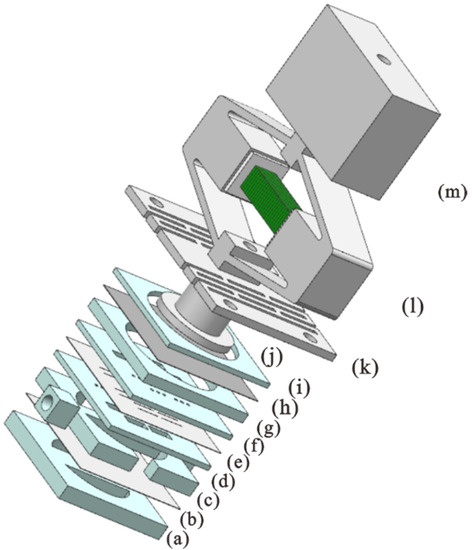
Figure 1.
Exploded view of the piezoelectric pump: (a) compressible spaces plate, (b) silicone diaphragm, (c) flow channel plate, (d,f) check valves seat plate, (e) film of check valves, (g) pump channel plate, (h) PVC diaphragm, (i) fixed plate, (j) coupler, (k) slotted beam, (l) displacement amplifier and piezoelectric stack, and (m) mass block.
The pump body, which is made of polymethylmethacrylate (PMMA), is mainly assembled by a multi-layer structure with different functions. It is mainly composed of a pump chamber, check valves, flow channel, compressible spaces, and coupler. The pump chamber film adopts relatively soft polyvinyl chloride (PVC) film, which reduces the influence of tension on the vibrator output. The check valves are manufactured using a PDMS thin film, which is sandwiched between two PMMA plates. It is cut into a two-fixed-end beam. Compared with the traditional single-fixed-end cantilever beam valve, the structure is simple and the leakage rate is low. The compressible space is composed of a PMMA flow channel plate, PDMS film, and PMMA compressible space plate with two semicircular holes. It is designed below the check valves, which can effectively reduce the fluid load of the rigid pump body and improve the output performance of the piezoelectric pump.
2.2. Fabrication
The three-dimensional (3D) picture and a photograph of the piezoelectric pump is shown in Figure 2a,b. This pump is mainly composed of a piezoelectric vibrator, pump body, and base. The pump body is fixed in the U-shaped base and connected with the vibrator through the coupler. The manufacture of a resonant piezoelectric pump mainly includes a piezoelectric stack, displacement amplifier, slotted beam, pump body, and U-shaped base.
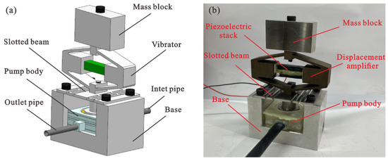
Figure 2.
(a) Mechanical structure of the piezoelectric pump and (b) photograph of the fabricated piezoelectric pump.
The piezoelectric stack is made of piezoelectric sheets (PZT-4), and the size is . It is bonded with 26 piezoelectric sheets, and the size of the piezoelectric stack is . The fabrication of the piezoelectric stack can be divided into eight steps: picking and pretreating piezoelectric sheets, stacking and pasting the piezoelectric sheets together, sanding the sides of the piezoelectric stack, coating sides with insulating cement, marking the insulation, lead out positive and negative electrodes, polarizing piezoelectric stack, and overall insulation treatment. The piezoelectric stack made in the laboratory has the advantages of large output amplitude, good frequency response, and low price.
The displacement amplifier is made of 65 manganese steel and processed using the drilling machine and the wire cutting machine, with a size of . The structure and parameters of the displacement amplifier are shown in Figure 3a. When assembling the piezoelectric stack, the short axis direction of the displacement amplifier is fixed with a clamp, and the applied preload is measured with a pressure sensor. An alumina sheet is placed at both ends of the piezoelectric stack to insulate it from the displacement amplifier and fill in the gap, and then it is placed in the middle of the displacement amplifier. When the preload is 400 N, the clamp is loosened, and the piezoelectric stack will be clamped on the displacement amplifier, thereby completing the preloading of pressure.
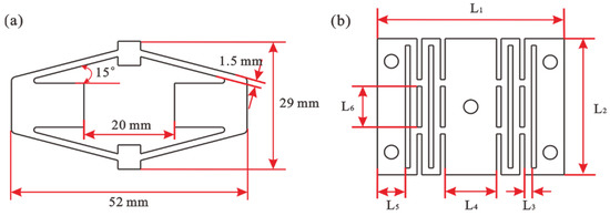
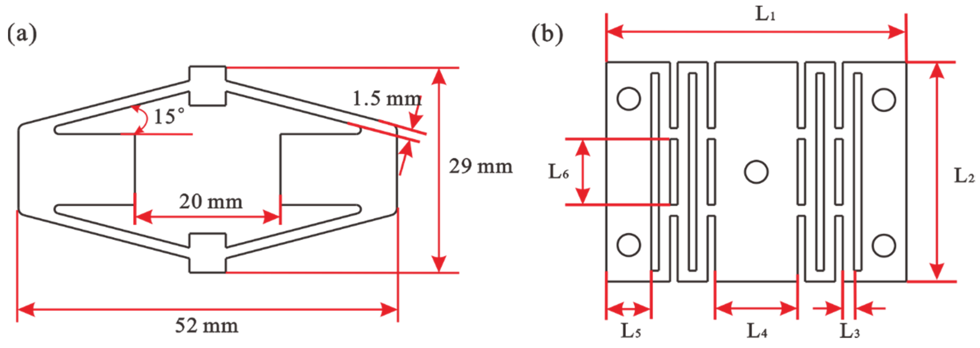
Figure 3.
(a) Dimensional parameters of displacement amplifier and (b) structure and parameters of the slotted beam.
The slotted beam is made of 304 stainless steel by laser cutting, the cutting accuracy is 0.05 mm, which can meet the accuracy requirements, and the shape will not be distorted. The beam adopts the slit treatment, in which the slit is symmetrical, and a uniform strain distribution can be obtained when the force is applied in the middle. The slotted beam presents an arched structure and has considerable elasticity. It is used as a flexure hinge for the connection between the vibrator and pump body. According to the experimental requirements, nine kinds of slotted beams with different stiffnesses are designed. Under the condition of keeping the overall size unchanged, the stiffness of the overall structure is changed by changing the width and size of the arch beam, and then the influence of different stiffnesses on the output performance is studied. The structure and parameters of the beam are shown in Figure 3b. The constant parameters of the beam are 1.5 mm thick, L1 = 40 mm, L2 = 30 mm, and L5 = 6 mm. Four holes with a diameter of 3 mm are reserved at both ends for connection and fixation with the base. A hole with a diameter of 3 mm is reserved in the middle to connect the displacement amplifier and output end. The variable parameters are presented in Table 1.

Table 1.
Constant parameters of the fixed slotted beams (unit: mm).
The pump body is made of six PMMA plates with pre-designed patterns, and its size is . The PMMA plates are cut into the required graphics using a CNC laser processing machine. A piece of PVC film () and two pieces of PDMS film () are inserted between different PMMA plates to realize the functions of the pump chamber, check valves, and compressible spaces. The PVC film is laid flat on the pump channel and kept soft. Glue is used to bond with the PMMA plate to complete sealing. The check valve film is clamped between two check valve plates, and each valve port is cut twice using a scalpel to form the bridge-type check valves. The fluid can push away the elastic PDMS film from the small hole, and the fluid is blocked by the film from the other direction, thereby realizing one-way fluidity. According to the structural sequence shown in Figure 1, the pump body is bonded and assembled, and its surface is bonded with epoxy adhesive (DP460) to achieve sealing.
The piezoelectric pump base is made of aluminum alloy and processed using a CNC lathe. The base is U-shaped, and the pump body is bonded to the base by DP460. Both ends of the slotted beam are connected to the base by bolts.
2.3. Operation Principle
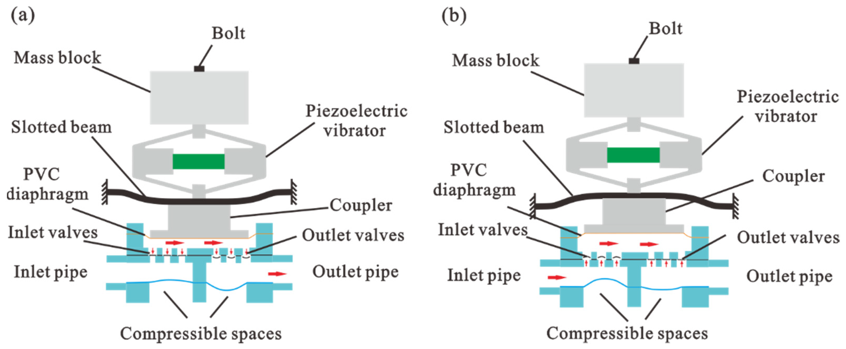
The operation principle of the diaphragm pump is shown in Figure 4. In the resonant state, the dispensing mode is shown in Figure 4a, and the displacement amplifier drives the slotted beam to bend and pushes the coupler to work downward, resulting in a reduction in the pump channel volume. As the pump chamber volume decreases and pressure increases, the inlet valves close and the outlet valves open. The liquid is squeezed out of the pump chamber through the out valves. Moreover, the liquid can immediately enter the compressible space instead of pushing all the liquid in the outlet pipe to move together. In the resonant state, the absorbing mode is shown in Figure 4b, and the displacement amplifier drives the slotted beam to bend and pushes the coupler to work upward, resulting in an increase in the pump channel volume. As the pump chamber volume increases and the pressure decreases, the inlet valves open and the outlet valves close. The compressible spaces at the inlet can reduce water flow load during suction. The resonant vibrator achieves the reciprocating motion in two modes and the check valves have one-way conduction characteristics, so the liquid is continuously input from the inlet pipe to the outlet pipe. The elastic compressible cavity structure can reduce the burden of the actuator, play the role of two energy accumulators, reduce the dynamic load of fluid quality, eliminate the fluctuation of flowing liquid, and increase the output flow of the pump system by about 20% [14].
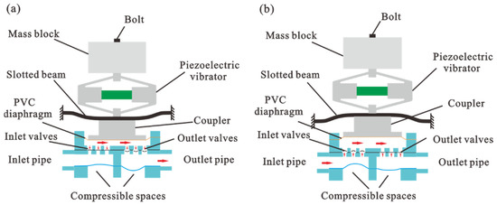
Figure 4.
Construction and operation principle of the proposed piezoelectric pump. (a) Dispensing mode and (b) absorbing mode.
3. Analysis and Modeling
3.1. Finite Element Analysis
The stiffness coefficient of the slotted beam and the size of the mass block are two important factors in the design of a piezoelectric pump. When the piezoelectric stack works, a reciprocal deformation of the vibrator is generated as a result of electromechanical conversion (reverse piezoelectric effect). Commercial software COMSOL 5.4 is used for modeling and simulation.
The piezoelectric vibrator consists of a displacement amplifier, a mass block, and a slotted beam. Through the finite element simulation, the resonant frequency and modal shape of the piezoelectric pump can be obtained, which provides theoretical support for the design of the piezoelectric pump [20]. The slotted beam is made of 304 stainless steel, the piezoelectric material is PZT-4, and the displacement amplifier and mass block are made of 65 manganese steel. Their material parameters are shown in Table 2. Through finite element simulation, the strain distribution of Prototype 9 is analyzed, as shown in Figure 5a,b. It can be seen from Figure 5a that the first-order resonant frequency of the slotted beam is 1856.7 Hz, the slotted beam is fixed at both ends and bent in the middle, and the maximum strain is concentrated in the middle. It can be seen from Figure 5b that the strain is uniform and symmetrical through static structural simulation, showing an arch spring structure, and the stiffness coefficient is 610.9 . Moreover, the connection between the two arches plays a fixed role. When one end of the arch spring structure is fixed, it not only amplifies the amplitude and concentrates the output at one end of the structure, but also realizes the decoupling of elasticity and mass. Because the liquid pumped by the piezoelectric pump is water, which is driven by the soft PVC film, in order to simplify the calculation, the PVC film is used instead of the pump body to simplify the fluid structure coupling effect of the complex pump body, and the finite element simulation of the piezoelectric pump is carried out. Figure 5c shows the resonant frequency and modal shape of the piezoelectric pump during working. In the third-order resonant state, the modal shape of the vibrator meets our working requirements. At the same time, according to the finite element simulation, the resonant frequency is 300.8 Hz.
Table 2.
Material parameters of the actuator.
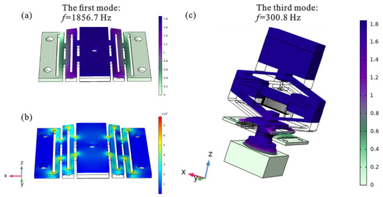
Figure 5.
(a) Modal simulation result of the slotted beam; (b) static structural simulation result of the slotted beam; (c) modal simulation result of piezoelectric pump.
The separation design of the displacement amplifier and slotted beam can reduce the overall stiffness of the vibrator. The input stiffness of the displacement amplifier is 19 and the output stiffness is 0.78 . The stiffness of the slotted beam is less than the output stiffness of the displacement amplifier. Through the step-by-step decrease in stiffness, it can not only give play to the small displacement and large output force of the piezoelectric stack, but also cooperate with the slotted beam to reduce the resonant frequency and increase the elastic output.
3.2. Theoretical Model
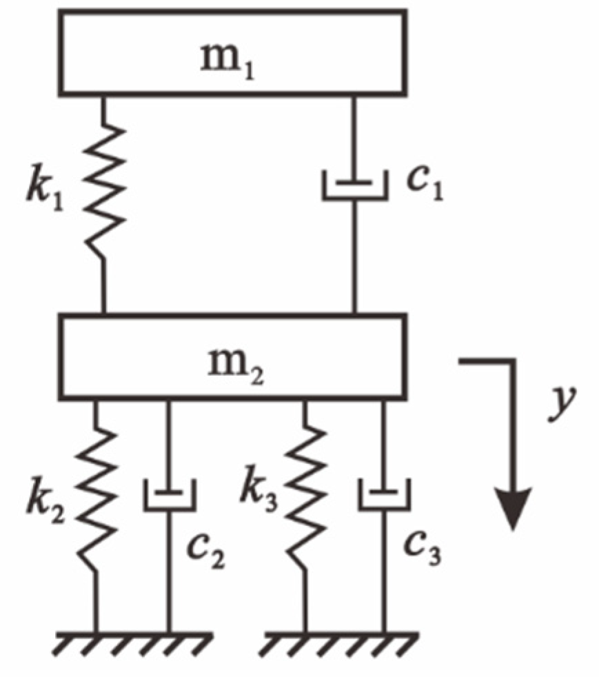
The dynamic model of the resonant piezoelectric pump is established as shown in Figure 6. The piezoelectric stack is used as the driving source. is the output force, is the excitation signal, y is the displacement of the slotted beam, is the equivalent mass of the displacement amplifier and mass block, and is the equivalent mass of the slotted beam and coupler. The equivalent stiffness and damping coefficient of the displacement amplifier are and , the equivalent stiffness and damping coefficient of the slotted beam are and , and the equivalent stiffness and damping coefficient of the diaphragm pump are and , respectively.
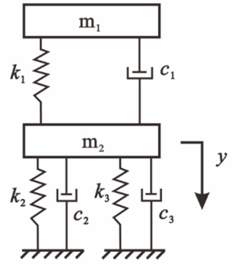
Figure 6.
Theoretical model of the piezoelectric pump.
The resonant frequency of the slotted beam is given in Equation (1).
In the whole system, because the displacement amplifier is used as the driving source, it is studied as an equivalent mass block. The equivalent stiffness of the whole drive system is . The equivalent mass is , and the resonant frequency of the system is given in Equation (2).
According to Equation (2), the resonant frequency of the displacement amplifier is mainly related to the stiffness of the slotted beam and the equivalent mass of the vibrator.
The mass block and displacement amplifier are regarded as the mass load of the slotted beam. The second-order dynamic model of the slotted beam is established, as shown in Equation (3).
The displacement response formula is obtained according to Equation (3).
where , is the relative damping coefficient, is the natural frequency of the undamped system, is the frequency ratio, and m is the overall equivalent mass of the vibrator. Therefore, the inertial driving force of the displacement amplifier under sine wave excitation is obtained, as shown in Equation (5).
When , the system resonates and the inertial output force of the vibrator is the largest. The equation can be simplified to Equation (6).
According to Equation (6), under the condition of constant damping coefficient and driving voltage, the main factors affecting the inertial output force are amplitude, stiffness coefficient, and mass.
4. Experimental Setup
A prototype pump system is manufactured, and the characteristics of the system are studied thereafter with the experimental device, as shown in Figure 7. A signal generator (DG1022U, RIGOL, Beijing, China) generates sinusoidal driving signals with different frequencies and voltages. The signal is amplified by the power amplifier (LYF-800AS, Nantong, Jiangsu, China) to drive the piezoelectric stack to work. A digital oscilloscope (TBS1102b, Tektronix, Beaverton, OR, USA) is used to monitor the excitation voltage signal, and a laser displacement sensor (OPTONCDT 2300, Micro-Epsilon, Beijing, China) is used to measure the amplitude of the piezoelectric vibrator. An electronic scale is used to measure the mass of liquid flowing out from the outlet within the set time interval, so as to obtain the flow rate. Tap water is used as the working fluid.
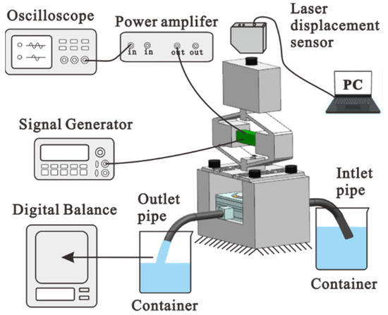
Figure 7.
Experimental setup of the piezoelectric pump system.
5. Results and Discussion
In this paper, a piezoelectric pump driven by the inertial force of a vibrator supported by a slotted beam is designed and manufactured. The inertial output force of the vibrator is qualitatively studied, and the law of stiffness and mass on the inertial force is obtained. The influence on the output performance is verified by experiments.
5.1. Stiffness Characteristics of the Slotted Beam
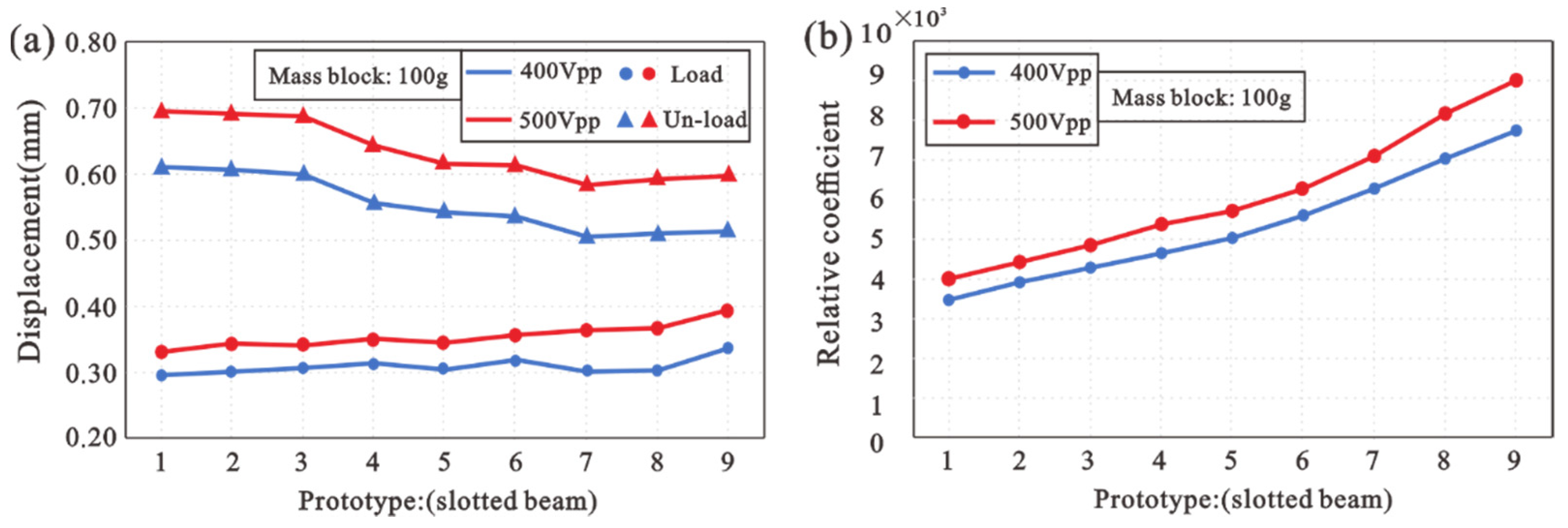
As an elastic element, a slotted beam forms a spring damping system with the pump body, so the stiffness of the slotted beam is an important factor. The structure of the slotted beam can make the beam have significant deformation and elasticity. Nine kinds of slotted beams with different stiffnesses (Table 1) are designed for comparison. The output amplitude of the vibrator under unload and load is studied, and the experimental results are shown in Figure 8a. When the vibrator is unloaded, the displacement decreases gradually with the stiffness coefficient. When the vibrator is loaded (driving fluid), the displacement increases gradually with the stiffness coefficient. Therefore, with the increase in stiffness coefficient, the displacement difference between unload and load becomes smaller. This is reflected in the increasing ability of the vibrator to overcome liquid resistance. According to Equation (6), Matlab/Simulink analysis is carried out when the driving voltage and equivalent mass remain unchanged. The stiffness and amplitude are variables, and the inertial output force is a dependent variable. An output inertial force coefficient R is obtained through calculation. As shown in Figure 8b, the output inertial force gradually increases with stiffness. Compared with the experimental phenomenon, it is proven.
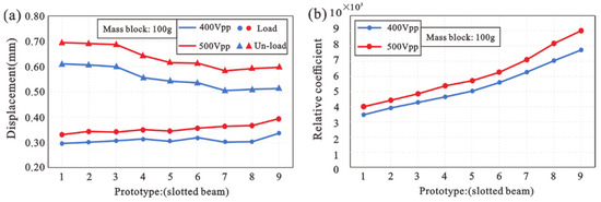
Figure 8.
(a) Amplitude when the vibrator with different stiffness is not loaded; (b) the variation trend of inertial output force coefficient with different stiffness.
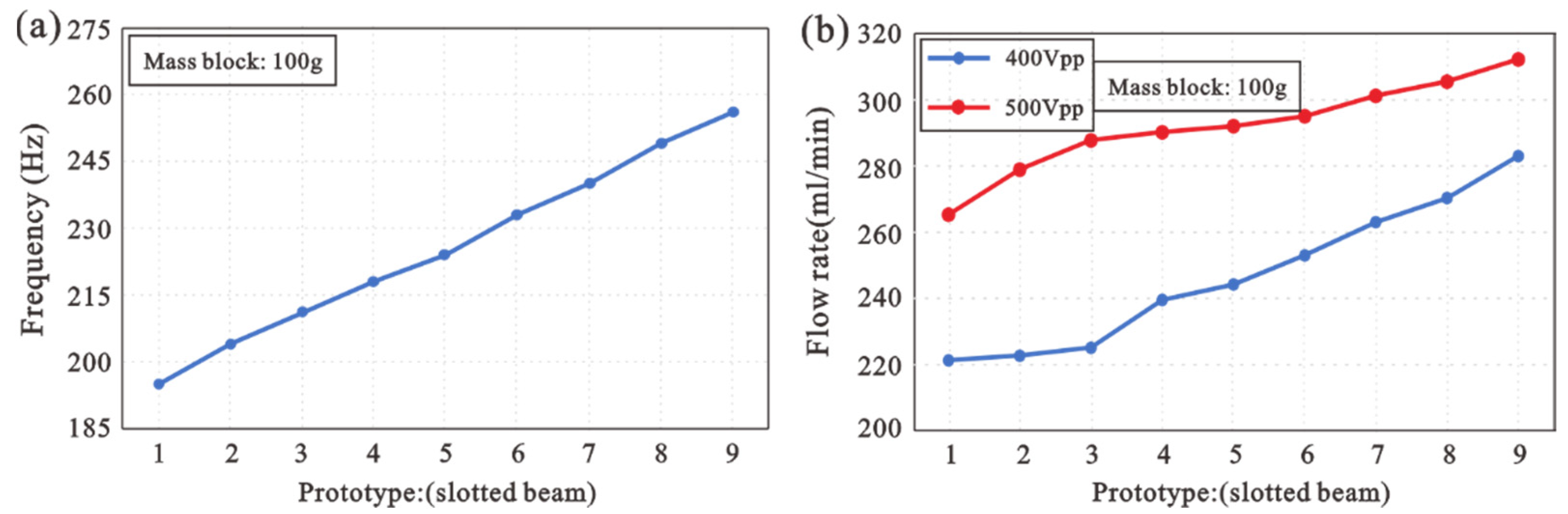
When the vibrator drives the pump body to work, the resonant frequency and maximum flow rate are studied as follows. Figure 9a shows that the greater the stiffness coefficient of the slotted beam, the higher the resonant frequency. The flow rate trend in Figure 9b corresponds to the displacement. The experimental results show that within a certain stiffness coefficient range, the greater the stiffness coefficient, the greater the output inertial force. Therefore, the output performance of the piezoelectric pump is better.
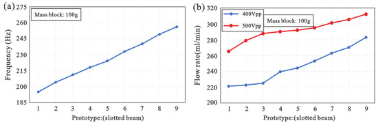
Figure 9.
Influence of slotted beam stiffness on (a) frequency, (b) flow rate.
5.2. Influence of the Mass Block
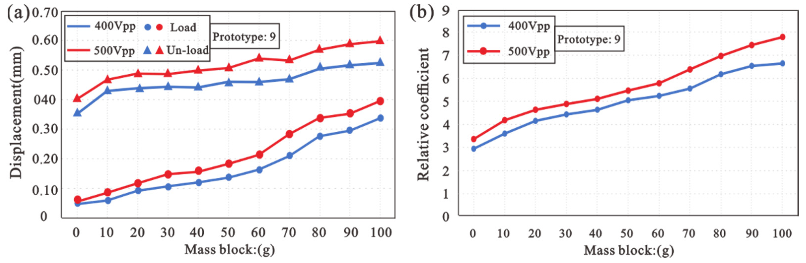
Using the slotted beam of Prototype 9, the influence of the mass block on output performance is studied. In this study, the displacement of the vibrator with different mass blocks under unload and load are measured, as shown in Figure 10a. When the vibrator is unloaded and loaded (driving fluid), the displacement increases gradually with the increase in mass block. However, with the increase in mass, the displacement difference between unload and load decreases gradually, that is, the ability to overcome liquid resistance becomes stronger and stronger. This is reflected in the increasing ability of the vibrator to overcome liquid resistance. Through Equation (6), when the driving voltage and stiffness coefficient remain unchanged, the equivalent mass and amplitude are changed, and the output inertial force coefficient R is obtained by Matlab/Simulink analysis. As shown in Figure 10b, with an increase in mass blocks, an upward trend is shown. Theoretical analysis and experimental results show that the higher the mass block, the greater the inertial output force, and the better the output performance of the piezoelectric pump.
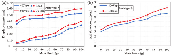
Figure 10.
(a) Amplitude when the vibrator with different mass blocks is not loaded; (b) the variation trend of inertial output force coefficient with different mass blocks.
When the vibrator drives the pump body to work, the results of their resonant frequency and maximum flow rate are as follows. As shown in Figure 11a, the resonant frequency gradually decreases with the increase in mass block. As shown in Figure 11b, the output flow increases gradually. In this paper, a 100 g mass block is used for research, so as to obtain a greater output while controlling the mass and size of the piezoelectric pump.
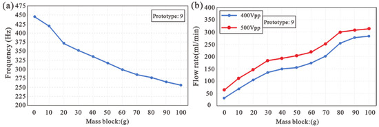
Figure 11.
Influence of the mass block on (a) frequency, (b) flow rate.
5.3. Frequency Response
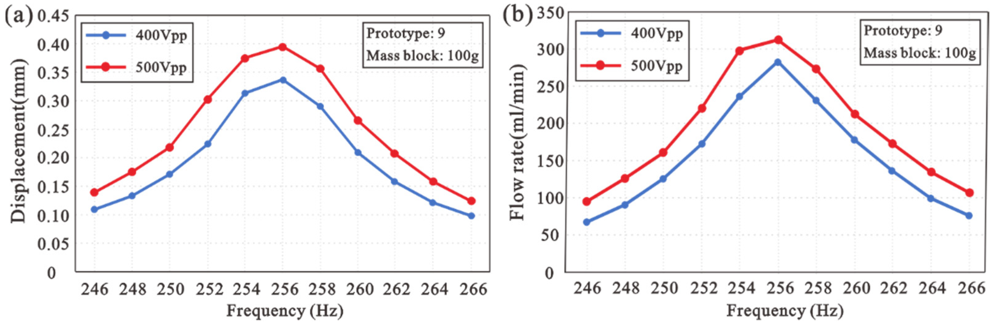
The piezoelectric pump with the slotted beam of Prototype 9 and a 100 g mass block is studied. The displacement and flow rate characteristics varying with frequency under zero backpressure are studied. The experimental results are shown in Figure 12a,b, and the relationship between the tip displacement (peak–peak value) of the vibrator and excitation frequency presents a typical resonance curve. When the driving frequency deviates from the resonant frequency, the displacement of the vibrator decreases significantly. When the driving frequency is 256 Hz, displacement and flow rate are the largest. When the driving voltage is 400 , the maximum displacement is 0.337 mm and the maximum flow rate is 283 mL. When the driving voltage is 500 , the maximum displacement is 0.395 mm and the maximum flow rate is 312.2 mL.
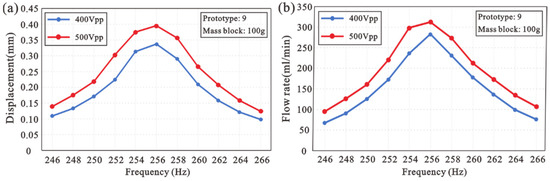
Figure 12.
Frequency responses of (a) displacement and (b) flow rate.
5.4. Influence of the Driving Voltage
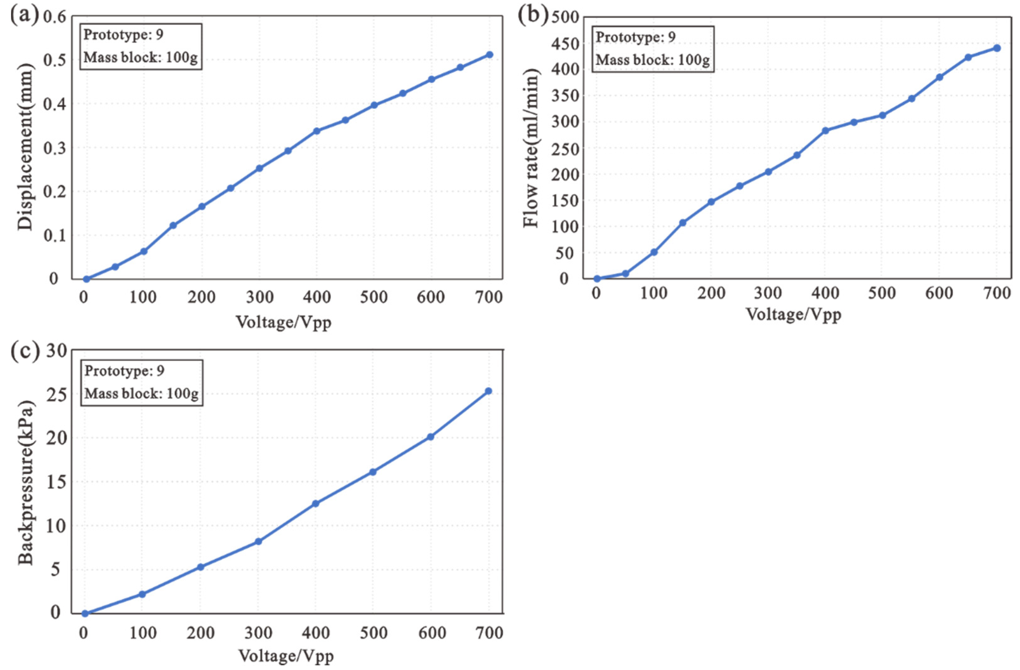
The output performance of the piezoelectric pump increases with the driving voltage. As shown in Figure 13a–c, a good linear relationship exists among displacement, flow rate, backpressure, and driving voltage. The flow rate of 441 mL can be obtained with this piezoelectric pump at a driving voltage of 400 and driving frequency of 256 Hz. When the flow rate is zero, the maximum backpressure is 25 kPa.
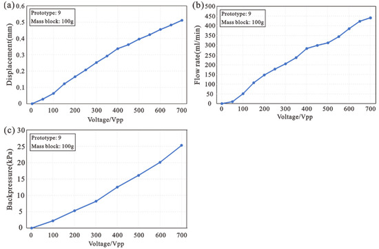
Figure 13.
Influence of the driving voltage on (a) displacement, (b) flow rate, and (c) backpressure.
6. Conclusions
This paper introduces a piezoelectric pump driven by the inertial force of a vibrator supported by a slotted beam. Through the finite element analysis of COMSOL 5.4, the strain distribution and stiffness parameters of the slotted beam are obtained. The design of the slotted beam optimizes the output of the displacement amplifier. In this study, the inertial output force of the vibrator is qualitatively analyzed by Matlab/Simulink. The influence of different mass blocks on the output performance is studied. Nine kinds of slotted beam with different stiffnesses are fabricated and assembled into a piezoelectric pump for experimental comparison. The experimental results are as follows: (a) The slotted beam acts as a flexible hinge that supports the vibrator and augments elastic output. Thus, the stiffness coefficient of the slotted beam is an important parameter that affects the output performance. (b) The mass block can reduce the resonant frequency of the vibrator. According to qualitative analysis, it can also increase the inertial output force of the vibrator, thus improving the output performance of the piezoelectric pump. (c) According to the experimental studies on different stiffness coefficients and mass blocks, the laws that affect the output performance of the piezoelectric pump are concluded. Therefore, considering the size of the piezoelectric pump, a 100 g mass block is used for research in this paper. The slotted beam of Prototype 9 is used for study, and when the driving voltage is 700 , the maximum output flow is 441 mL and the maximum back pressure is 25.3 kPa.
The design of resonant piezoelectric pump makes use of the characteristics of large output force and small displacement of the piezoelectric stack. This structure has the advantages of simple structure, concentrated output, low energy loss, and high work efficiency.
Author Contributions
Conceptualization, writing—review and editing, supervision, project administration, and funding acquisition, Q.P.; review and editing, supervision, project administration, and funding acquisition, Y.Z. and S.L.; methodology, FEA software, and writing—original draft preparation, X.W. All authors have read and agreed to the published version of the manuscript.
Funding
This work was supported in part by the National Major Scientific Instrument Development Project: Design and Integration of Air Flotation Carrier Unit (Grant No. 2013YQ22074903), the Project of National Natural Science Fund of China (Grant Nos. 52175533), The Major Research and Development project of Anhui Province (Grant No. 202104h04020025), and the Fundamental and Research Funds for the Central Universities (Grant No. PA2021KCPY0049).
Institutional Review Board Statement
Not applicable.
Informed Consent Statement
Not applicable.
Data Availability Statement
The data presented in this study are available upon reasonable request from the authors.
Conflicts of Interest
The authors declare no conflict of interest.
References
- Kim, C.N. Internal pressure characteristics and performance features of the piezoelectric micropumps with the diffuser/nozzle and electromagnetic resistance. Comput. Fluids 2014, 104, 30–39. [Google Scholar] [CrossRef]
- Li, H.Y.; Liu, J.K.; Li, K.; Liu, Y.X. A review of recent studies on piezoelectric pumps and their applications—ScienceDirect. Mech. Syst. Signal Processing 2021, 151, 107393. [Google Scholar] [CrossRef]
- Wang, Y.N.; Fu, L.M. Micropumps and biomedical applications—A review. Microelectron. Eng. 2018, 195, 121–138. [Google Scholar] [CrossRef]
- Mohith, S.; Karanth, P.N.; Kulkarni, S.M. Recent trends in mechanical micropumps and their applications: A review. Mechatronics 2019, 60, 34–55. [Google Scholar] [CrossRef]
- Liu, G.J.; Shen, C.L.; Yang, Z.G. A disposable piezoelectric micropump with high performance for closed-loop insulin therapy system. Sens. Actuators A Phys. 2010, 163, 291–296. [Google Scholar] [CrossRef]
- Bußmann, A.; Thalhofer, T.; Hoffmann, S.; Daum, L.; Surendran, N.; Hayden, O.; Hubbuch, j.; Richter, M. Microfluidic Cell Transport with Piezoelectric Micro Diaphragm Pumps. Micromachines 2021, 12, 1459. [Google Scholar] [CrossRef] [PubMed]
- Tseng, L.Y.; Yang, A.S.; Lee, C.Y.; Cheng, C.H. Investigation of a piezoelectric valveless micropump with an integrated stainless-steel diffuser/nozzle bulge-piece design. Smart Mater. Struct. 2013, 22, 085023. [Google Scholar] [CrossRef]
- Liu, C.; Zhu, Y.C.; Wu, C.W. Optimization of a synthetic jet based piezoelectric air pump and its application in electronic cooling. Microsyst. Technol. 2020, 26, 1–10. [Google Scholar] [CrossRef]
- Bertin, M.; Plummer, A.; Bowen, C.; Johnston, N.; Griffiths, M.; Bickley, D. A dual lane piezoelectric ring bender actuated nozzle-flapper servo valve for aero engine fuel metering. Smart Mater. Struct. 2019, 28, 115015. [Google Scholar] [CrossRef]
- Lee, D.S.; Ko, J.S.; Kim, Y.T. Bidirectional pumping properties of a peristaltic piezoelectric micropump with simple design and chemical resistance. Thin Solid Film. 2004, 468, 285–290. [Google Scholar] [CrossRef]
- Kim, J.H.; Kang, C.J.; Kim, Y.S. A disposable polydimethylsiloxane-based diffuser micropump actuated by piezoelectric-disc. Microelectron. Eng. 2004, 71, 119–124. [Google Scholar] [CrossRef]
- Ma, H.K.; Hou, B.R.; Wu, H.Y.; Lin, C.Y.; Gao, J.J.; Kou, M.C. Development and Application of a Diaphragm Micro-Pump with Piezoelectric Device. Microsyst. Technol. 2008, 14, 1001–1007. [Google Scholar] [CrossRef] [Green Version]
- Wang, X.Y.; Ma, Y.T.; Yan, G.Y.; Huang, D.; Feng, Z.H. High flow-rate piezoelectric micropump with two fixed ends polydimethylsiloxane valves and compressible spaces. Sens. Actuators A Phys. 2014, 218, 94–104. [Google Scholar] [CrossRef]
- Wang, J.T.; Zhao, X.L.; Chen, X.F.; Yang, H.R. A Piezoelectric Resonance Pump Based on a Flexible Support. Micromachines 2019, 10, 169. [Google Scholar] [CrossRef] [PubMed] [Green Version]
- Lee, D.G.; Or, S.W.; Carman, G.P. Design of a Piezoelectric-hydraulic Pump with Active Valves. J. Intell. Mater. Syst. Struct. 2004, 12, 107–115. [Google Scholar] [CrossRef]
- Woo, J.M.; Sohn, D.K.; Ko, H.S. Performance and Flow Analysis of Small Piezo Pump. Sens. Actuators A Phys. 2020, 301, 111766. [Google Scholar] [CrossRef]
- Valdovinos, J.; Carman, G.P. Development of a low-voltage piezohydraulic pump for compact hydraulic systems. Smart Mater. Struct. 2015, 24, 125008. [Google Scholar] [CrossRef]
- Park, J.H.; Seo, M.Y.; Ham, Y.B.; Yun, S.N.; Kim, D.I. A study on high-output piezoelectric micropumps for application in DMFC. J. Electroceramics 2013, 30, 102–107. [Google Scholar] [CrossRef]
- Yang, Y.; Chen, J.; Ren, Y.J.; Feng, Z.H. Valve improvement for high flow rate piezoelectric pump with PDMS film valves. Sens. Actuators A Phys. 2018, 283, 245–253. [Google Scholar]
- Yu, H.H.; Hui, T.H. Solid-liquid coupled vibration characteristics of piezoelectric hydroacoustic devices. Sens. Actuators A Phys. 2016, 238, 177–195. [Google Scholar]


Publisher’s Note: MDPI stays neutral with regard to jurisdictional claims in published maps and institutional affiliations. |
© 2022 by the authors. Licensee MDPI, Basel, Switzerland. This article is an open access article distributed under the terms and conditions of the Creative Commons Attribution (CC BY) license (https://creativecommons.org/licenses/by/4.0/).