Abstract
The research and development of the ocean has been gaining in popularity in recent years, and the problem of target searching and hunting in the unknown marine environment has been a pressing problem. To solve this problem, a distributed dynamic predictive control (DDPC) algorithm based on the idea of predictive control is proposed. The task-environment region information and the input of the AUV state update are obtained by predicting the state of multi-AUV systems and making online task optimization decisions and then locking the search area for the following moment. Once a moving target is found in the search process, the AUV conducts a distributed hunt based on the theory of potential points, which solves the problem of the reasonable distribution of potential points during the hunting process and realizes the formation of hunting rapidly. Compared with other methods, the simulation results show that the algorithm exhibits high efficiency and adaptability.
1. Introduction
It is always a challenging task to explore and develop the enormous, complex, and hazardous marine environment, and an autonomous underwater vehicle (AUV) is the best technical means to deal with the current challenges as it is an underwater device with good concealment, flexibility in underwater movement, economic applicability, and other technical characteristics of high-tech devices [1]. The reconnaissance efficiency of a single AUV is low because of realistic conditions such as limited energy consumption and restricted communication. Therefore, greater multi-AUV collaborative operation is required. In order to accomplish underwater tasks better, the AUV needs to have capabilities of adaptive searching, decision-making and dynamic target hunting. Therefore, how to utilize limited resources rationally and coordinate AUVs to complete target searching and hunting are the most critical problems.
For the problem of multiple-agent-system target searches in an unknown environment, extensive research has been carried out [2]. Liu et al. establish the distributed multi-AUVs collaborative search system (DMACSS) and proposed the autonomous collaborative search-learning algorithm (ACSLA) be integrated into the DMACSS. The test results demonstrate that the DMACSS runs stably and the search accuracy and efficiency of ACSLA outperform other search methods, thus better realizing the cooperation between AUVs and allowing the DMACSS to find the target more accurately and faster [3]. A fuzzy-based bio-inspired neural network approach was proposed by Sun for multi-AUV target searching, which can effectively plan search paths. Moreover, a fuzzy algorithm was introduced into the bio-inspired neural network to make the trajectory of AUV obstacle avoidance smoother. Simulation results show that the proposed algorithm can control a multi-AUV system to complete multi-target search tasks with higher search efficiency and adaptability [4]. For multiple AUVs, Yao et al. proposed bidirectional negotiation with a biased min-consensus (BN-BMC) algorithm to determine the allocation and prioritization of sub-regions to be searched and utilized an adaptive oval–spiral coverage (AOSC) strategy to plan the coverage path within each sub-region. Dubin’s curve is the taken path satisfying the AUV kinematic constraint as the transition path between sub-regions [5]. Yue et al. presented a combinatorial option and reinforcement learning algorithm for a target search against unknown environments, which improves the dynamic characteristics by reinforcement learning in the unknown environment to handle real-time tasks [6]. However, this kind of study method is not adaptable in an unknown working environment, with real-time performance and the target search efficiency is reduced. Luo et al. put forward a kind of biological heuristic in unknown environments such as a neural network algorithm [7]. The weight transfer attenuation process between neurons is constructed in the environment so as to construct a real-time map and realize the robot’s search in the unknown two-dimensional environment. However, due to the limited sonar detection range, this method can only be applied to target searches in local unknown environments. An improved PSO-based approach was proposed by Cai et al. for robot cooperative target searching in unknown environments, which used the potential field function as the fitness function of the particle swarm optimization (PSO) algorithm [8]. The unknown areas are divided into different search levels and the collaborative rules are redefined. Dadgar et al. proposed a distributed method based on PSO to overcome robot workspace limitations so that the PSO-based algorithm could achieve the overall optimum under a global mechanism [9]. A local PSO algorithm based on information fusion and sharing was proposed by Saadaoui et al. for collaborative a target search algorithm [10]. In addition, the probabilistic map and the deterministic map were established for searching a location based on the map data. Finally, the path was planned by PSO algorithm for further confirmation of the target. A reinforcement learning algorithm was applied to snake-game by Wu et al. to simulate the process of an unmanned aerial vehicle (UAV) searching for targets in an unknown area to simulate the process of a snake searching for fruit [11]. S Ivić et al. proposed the search algorithm of the dynamic system traversal theory for the specific case of MH370, combining optimal search theory with traversal theory [12].
For the problem of hunting a dynamic target, Wang et al. came up with a method to let robots form a pursuit team through negotiation, and then the team carried out cooperative pursuit according to the motion multi-target cooperative pursuit algorithm [13]. Wang et al. proposed an optimal capture strategy based on potential points, and the ant colony algorithm was used to realize capture and collision avoidance during the AUV task [14]. Taking into account port security issues, Meng et al. proposed a predictive planning interception (PPI) algorithm for dynamic targets [15]. The underwater vehicle predicts the target position by tracking the target, and the path to the target is planned by artificial potential field method in advance for interception. However, due to the randomness and uncontrollability of moving targets, it is often difficult to achieve advanced interception. Cao et al. used polynomial fitting to dynamically update the sampling points to find the navigation rules of the dynamic target, and then the reinforcement learning algorithm was used to find the shortest path to capture the target [16].
In conclusion, in view of the various interference factors in the unknown underwater environment and the limitations of its own search capacity and energy expenditure, the distributed dynamic predictive control (DDPC) search method is proposed. For the problem of hunting dynamic targets, a dynamic distribution method is proposed to make a reasonable distribution of potential points around the target, which allows the AUV to improve the accuracy and the rapidity of hunting.
The structure of this article is divided into following parts: Section 2 shows the model establishment; the process of searching and hunting are presented in Section 3; Section 4 describes DDPC algorithm; the details of simulation setup and results are given in Section 5; and ultimately, the conclusions and future work are summarized in Section 6.
2. Mathematical Modeling
2.1. The Environment Model
This paper divides the region into two levels [17]. Information such as the traversal status, search results, and area coverage of the area can be better obtained during the execution of the task by the grid division of the search area. The size of the first-level sub-region is related to the distance the AUV moves over a predicted time step, and the second-level sub-region is consistent with the effective detection range of the AUV sonar. The state information structure contained in different level regions and how it is updated is discussed in detail in Section 3.2.1. As shown in Figure 1, the bright red box represents the first-level sub-region while the dark red box represents the second-level sub-region, and the blue number represents the first-level sub-region number and the black number represents the second-level sub-region number.
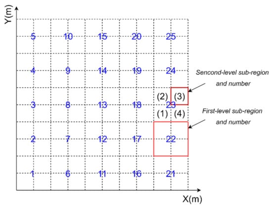
Figure 1.
Environment map.
2.2. The AUV Kinematic Model
According to the definition in reference [18], two reference coordinate systems are adopted, namely the earth-fixed reference coordinate system and the body-fixed reference coordinate system, respectively, which include velocity vector , angular velocity vector, and attitude angle vector , as shown in Figure 2.
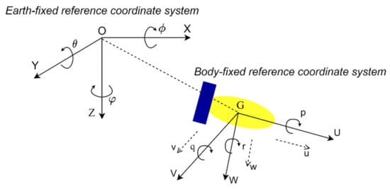
Figure 2.
Earth-fixed reference coordinate system and body-fixed reference coordinate system.
The AUV kinematic model is as follows:
Normally, in a two-dimensional environment, the kinematics model of AUV is usually simplified as:
2.3. Forward-Looking Sonar Model
The mathematical model was established according to the real sonar working principle [19]. The detection radius of sonar is , open angle of horizontal detection is and the detection angle of depth is . The array statistic matrix is established according to the open angle range of sonar and judging whether there is a target in the visible range through the array elements in the matrix. It can be simply represented as in Figure 3.
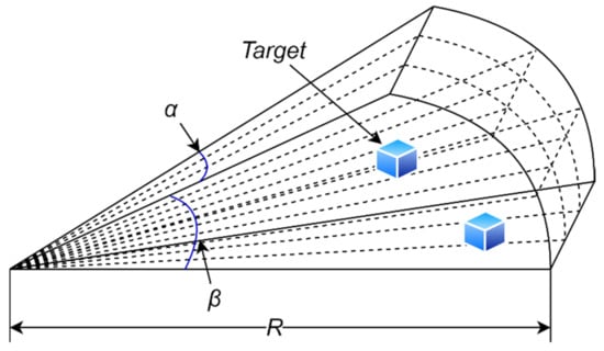
Figure 3.
Simplified sonar model.
The mathematical model between the object and sonar is established. In a two-dimensional environment, the targets for which information is available should meet the following requirements:
where is as follows:
where represents position coordinate of the object and is the coordinate of sonar under the body coordinate system.
Forward-looking sonar is prone to interference by external noise in the process of collecting underwater information, which affects the detected data. Therefore, interference noise is added to the sonar model to simulate the attenuation of the visual field and obstruction of obstacles, which are specifically described as follows:
where is the environmental characteristic information detected by sonar, is the sonar effective detection range, is the sonar detection function under noise-free interference, is the distance between the detected target, and sonar at time n, and denotes the nonlinear interference. When or the object to be detected is blocked by obstacles, the environmental characteristics information cannot be detected.
2.4. Target Model
It is assumed that all targets are regarded as particles. The model of a static target is shown as:
where, and , respectively, represent the coordinate and velocity of the target in the X-axis direction at time n+1, and and , respectively, represent the coordinate and velocity in the Y-axis direction at time n + 1. and are identical to 0 when the target is static.
It is assumed that dynamic targets move at the same depth and perform uniform circular motion [20]. The discrete time equation of dynamic targets can be described as follows:
where represent the turning angular velocity and sampling time, respectively.
2.5. Multiple AUV Communication Content
In order to realize multi-AUV cooperative searching and hunting, this paper analyzes the information interaction content of AUV systems. The communication contents are shown in Table 1, which are the AUV state information, target information and sub-region state information.

Table 1.
Communication in multi-AUV system.
The communication mode is such that each AUV exchanges information in the form of broadcast over a period of time so that each AUV can obtain the information content of the global environment, thus realizing collaborative searching and hunting.
3. The Distributed Dynamic Predictive Control Algorithm
3.1. The Searching and Hunting Process
According to the task requirements, the problem of target search for AUV can be described as: static and moving targets, random obstacles, and AUVs are randomly distributed in the mission area. The cooperative control of multiple AUVs is required to search for as many unknown targets as possible with lower search cost and limited time [21].
In the target search process, the AUV marks the location of static targets; for the moving target, the first AUV which discovers moving target is confirmed as an organizer, and then a hunting message is sent to other AUVs according to the distance between the AUV and target. After receiving the message, the AUVs sail around the predetermined hunting position at first, and then narrow down to the required formation to hunt the dynamic target. When the AUV encounters obstacles during the search mission, it switches from the search mode to the obstacle avoidance mode. After successfully avoiding the obstacle, it continues to perform the search task. The search flowchart is shown in Figure 4.
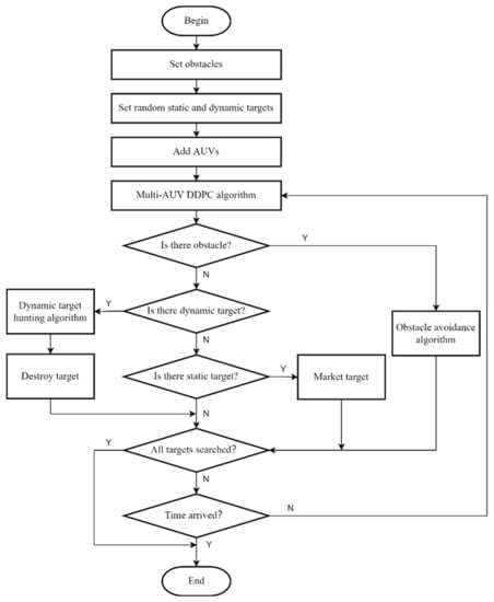
Figure 4.
Search flowchart.
3.2. The Distributed Dynamic Predictive Control Algorithm
The core of the DDPC algorithm is to predict the change of environment after each AUV obtains some prior information through communication, and then decides its next action based on the prediction. If the AUV can obtain the state of the mission environment area, multi-AUV system, and target for a period of time in the future when executing the target search decision, the entire system better adapts to the unknown underwater environment, which is the original purpose of the DDPC algorithm. Figure 5 shows the task execution process of the AUV system using the DDPC algorithm.
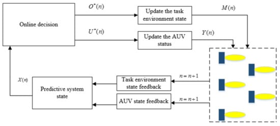
Figure 5.
DDPC algorithm.
- (1)
- AUV and environment state feedback: The system feeds back the state information changes of the AUV of the current actuator and the task environment model and the feedback information is used as the input of the system state prediction;
- (2)
- System state prediction: The state for the N steps in the future is dynamically predicted by the feedback information, and the predicted state of the current time n is obtained. The predicted state is represented by ;
- (3)
- Online task optimization decision: The algorithm is based on distributed dynamic prediction combined with optimization methods for online decision making, confirming the actuator state input information and area state information, which are and . , and are taken as the state inputs;
- (4)
- State updates for AUV and task area: updates the state of the actuator and the state information of the entire environmental area through decision input to obtain and , respectively, and finally controls the AUV system to perform collaborative target search.
3.2.1. Task Area State
The environment region is divided into discrete task first-level sub-regions, and each first-level sub-region contains a state information structure, as follows:
where describes the state of the first-level sub-region allocated by dynamic prediction, indicates that the first-level sub-region has not been allocated by prediction, and indicates the first-level sub-region has been allocated and is locked by the AUV. When the number of regions that are not predicted to be allocated is less than the AUV, the unlocking action does not proceed; is the traversal state of the sub-region at time n, which is defined as follows:
where denotes the distance between the AUV and the allocated sub-region, is the distance measure of the traversal degree of the sub-region, are the length and width of region, and is a dynamic regulator. represents the status value of the current first-level sub-region effectively traversed by AUV, which is defined as:
[0,1] represents the degree of certainty of target presence information in the current first-level sub-region.
Since the degree of certainty of the target existence information is obtained by observing the environment with sonar, the AUV is required to continuously conduct the search in the allocated area to update the target existence probability in the area. The update equation is as follows:
where, is the dynamic coefficient of the certainty degree of the target existence, is a binary vector, represents the target is found, and represents the absence of detection.
The first-level dynamic predictive search state information set of the AUV is defined as:
The first-level sub-region is divided into second-level sub-regions. There is an information structure for each of second-level sub-region , where represents the state information of the second-level sub-region traversed by the AUV at time n, represents the region that has not been traversed by the AUV, and represents the opposite and no other AUVs need to traverse it again. indicates the three states of the second-level sub-region at the time n. The three states are not locked, locked but not arrived, and locked and arrived. is expressed as follows:
where is the effective traversal state of the second-level sub-region at the time , which is defined as:
where represents the distance from the AUV to the predicted allocation sub-region center, represents the distance measure of the traversal degree of the second-level sub-region. represents the length and width of the second-level sub-region, and is the dynamic adjustment factor.
Similar to the certainty of target presence information update method in the first-level sub-region, the update equation of the currently locked second-level sub-region is defined as:
The parameter setting of Equation (21) is consistent with the parameter of Equation (17). The dynamic prediction search states of all the second-level sub-regions in a first-level sub-region are expressed as:
The dynamic predictive search states of the entire task environment region can be expressed as:
3.2.2. The AUV State
Assuming that the AUVs are executing the target search task at a certain depth of a horizontal plane, the state of each AUV is denoted as , where represents the position of the i-th AUV, the position coordinate is , and represents the heading angle of the AUV. The optimal decision input of the AUV is , where is the sailing speed of the AUV at time n, and is the heading deflection angle of the AUV, thus the state equation of the AUV is:
According to the decision input of AUV, the sailing distance in a period of time in the future is calculated, and the distance is mapped to the coordinate axis according to the AUV heading angle at the current time to obtain increment . The specific calculation is shown in the following formula:
3.3. The Function of Decision-Making
The purpose of the multi-AUV cooperative target search is to find targets and determine target information as much as possible within a certain mission area. Therefore, the following requirements need to be met:
- (1)
- Reduce the cost of multi-AUV cooperative target search;
- (2)
- Improve the determination degree of target information in the task area;
- (3)
- Allocate search area reasonably.
describes the comprehensive revenue of the multi-AUV system [22], which is a multi-objective synthesis function that needs to satisfy several conditions to make the final optimal solution.
This function comprehensively considers the regional target discovery revenue , environment target search revenue , execution cost , and the predicted allocation revenue of sub-regions in the task environment.
- (1)
- Regional target discovery revenue
The regional target discovery revenue of target searching is related to the degree of certainty of the target existence information in the first-level and the second-level sub-region allocated by the distributed predictive control method. The specific regional target discovery revenue is defined as:
where represents the target existence probability of the first-level sub-region where the k-th AUV is located in the task environment, which is related to the position of the AUV and the traversal state of the current sub-region. is a binary variable representing whether the target is found. The target is found when the deterministic probability of the target existence is greater than the threshold . The specific definition of is expressed as:
- (2)
- Environment target search revenue
The environment target search revenue is defined to be associated with the reduction of the target information uncertainty in the sub-region within the effective sensor detection range of the k-th AUV. The concept of target information entropy is introduced to describe the revenue, which is specifically defined as:
The information entropy is expressed as:
- (3)
- Execution cost
The execution cost of the multi-AUV system represents the comprehensive consumption in the target search process, which is generally expressed as the time consumption or energy consumption in the process of the AUV arriving from the current position to the predicted allocation area. Here, the estimation of N steps in the future is performed, and the specific representation is as follows:
- (4)
- Sub-region predicted allocation revenue
The sub-region predicted allocation revenue takes the change of the global environmental information due to the change of the sub-region information at time n into account. The algorithm can improve the certainty of regional target information during prediction, thereby reducing the uncertainty of the entire environment. The specific definition is expressed as:
where represents the dynamic prediction search states of the first-level sub-regions in the task area.
To sum up, under the conditions of the state of the AUV and the search state of the task area, after the multi-AUV cooperative target search system adopts the control input of the online task optimization decision, the optimization objective function of the entire system is defined as:
where, represents the state of AUV, represents the search state of the task area, and is the control input, is the weight coefficient, and the different weight coefficients reflect the degree of performance preference for the system. The weight coefficient should be adjusted appropriately according to specific task requirements. In addition, as the above revenues have different dimensions, it is necessary to conduct normalization before the summation.
3.4. System-State Prediction and Online Optimization Decision-Making
- (1)
- System-state prediction based on rolling optimization
Rolling optimization can be used as the solution method for the multi-AUV cooperative target search objective function of distributed dynamic predictive control. Using state equation and objective functions, an optimal rolling model for a multi-AUV system with n-step prediction is established. The system state and control input at time n + m are dynamically predicted at time n. Within a period of time, the overall performance index of the system is denoted as:
The rolling model of task optimization decisions for the multi-AUV system at time n is obtained as follows:
Finally, the state equation obtained according to the solution of the rolling model is expressed as:
In rolling time, the state input sequence of the AUV state space and regional information structure is obtained through online optimization and decision-making, which are and , respectively. Then, in the optimization sequence of the actuator is used as the input of the state of the actuator at the current moment, and is used as the state input of the task area, thereby changing the decision input of the actuator in the future.
By optimizing all performance indicators of the system, which include the state of the task environment area, the predictive control, and the decision-making optimization input, the optimal decision sequence of the entire system can be obtained. The rolling optimization model based on a certain time window can transform an infinite time domain optimization problem into a series of finite time domain optimization problems. Therefore, it is very suitable for the online dynamic solution process of state input.
- (2)
- The online task-optimization decision
In Formula (36), the solution of the cooperative target searching mode of the multi-AUV system through the rolling optimization model is generated by a centralized solution method, which requires a unified modeling of all the actuators and the determination of the central solution node of the system. The node can be unified for all of the multi-AUV system state information and task environment area state information and solve the optimal task decision and sub-region state update information for all members of the system. Such a centralized solution is very computationally intensive and time-consuming for a large and complex multi-AUV system. Therefore, this method limits the scale of the multi-AUV system the whole system’s decision-making and control capabilities.
When AUVs perform the target search task in each task sub-region, they are decoupled from each other, that is, they exist independently in the global task environment. The only interrelated factor is the state information of the task sub-region and the communication between the AUV. Therefore, in a system for such an independent state, the global state information of the agents can be obtained through the communication network between the AUVs and the state information exchange of the task sub-region based on the distributed dynamic predictive control method so as to achieve the purpose of the multi-AUV system for performing the target search cooperatively. The structure chart of the DDPC for the AUV system is shown in Figure 6.
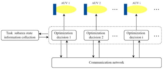
Figure 6.
Structure of DDPC algorithm.
The whole system is decoupled into independent small systems on the basis of distributed dynamic prediction. Supposing that the state equation of the K-th AUV is denoted as , then the whole system is shown as follows:
The task region state information is set as , then the whole system is:
Then, the optimization objective function of the entire multi-AUV system can be decomposed into the optimization objective function of each of AUVs, with the specific form as follows:
where, represents the optimization objective function of K-th AUV; is the weight coefficient; and denotes the state change of the task region at time n by the AUV. represent the dynamic prediction state and optimization decision input of the AUV, respectively; represents the influence of the other AUVs in the system on the environment state; represents the dynamic prediction state of the other AUVs; and represents the optimal decision input. The specific representation is shown below:
Aiming at the global optimization problem of the target search system, it can be decomposed into locally finite time domain problems. According to the solution of each AUV separately, the rolling optimization model of the K-th AUV is shown as follows:
Then, according to the solving conditions of the rolling model, the optimization decision input and the sub-region state information of each AUV are obtained, as shown in the following formula:
Finally, the state and decision variables of each optimization subsystem are obtained as follows:
It can be seen that the solution of the local optimization problem also contains the state of other AUV subsystems, the decision variables, and the state changes of sub-region, so the obtained solution is based on the AUV cooperation mechanism. The state of the other members of the system and the effects of decision-making information can be gained through communication. So the K-th AUV state and decision input are only associated with the current local state. The cooperative target search problem of the whole multi-AUV system becomes the optimization problem of the independent AUV and the update problem of the state information of the sub-region, which greatly reduces the optimization scale of the whole system.
4. The Hunting Algorithm
4.1. Hunting Formation
Considering the problems of the hunting task, this paper proposes a dynamically distributed hunting method which is suitable for hunting formation and transformation. The time that the AUV takes to adjust the heading is taken into account as the time consumption for forming the hunting formation during the analysis of the hunting conditions.
Suppose that there are three hunt executors with the target (red AUV in Figure 7) as the center of the hunting formation. According to the hunting critical diagram, the minimum value of the ratio of the speed of the hunting executor to the target is obtained as follows:
where represents the speed of the hunting executor, which is the same for all AUVs, and represents the speed of the moving target. By reasonable extrapolation, the general formula of the required speed for the hunting formation of the multiple-AUV system is shown as follows:
where is the serial number of the hunting AUV. According to Formula (45), it can be concluded that the greater the number of AUVs involved in hunting, the smaller the minimum moving speed required.
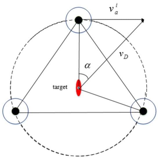
Figure 7.
Critical condition analysis diagram of hunting.
In this paper, the method of reducing the hunting circle is adopted to form an effective hunting formation for moving targets with a fixed number of AUVs. By analyzing this method, it can be concluded that the relation between the field angle of the target (as shown in Figure 8), the distance between the executor and the target and effective detection radius , is expressed as:
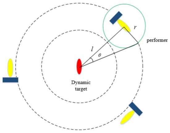
Figure 8.
Reduction of encirclement.
In the process when the AUV gets closer to the target to be hunted, with the reduction of the distance from the target, increases for the effective detection range, which is fixed, and thus the probability of the target escaping is reduced.
When the AUV reaches the effective range to be changed into a hunting formation, it moves to the respective hunting points for formation, as shown in Figure 9.
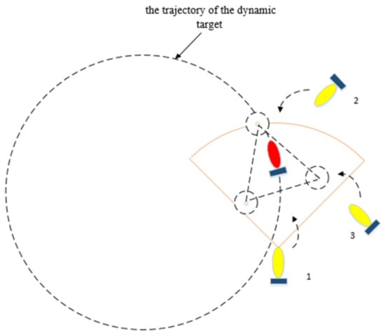
Figure 9.
The formation and maintenance of the encirclement.
4.2. Formation of the Hunting Potential Point
In order to ensure the rapidity and effectiveness of hunting, it is necessary to develop an appropriate method for the formation of hunting potential points [9]. Assuming that the position of the moving target is and the speed and heading angle are and , respectively, then the coordinate formula of the hunting point is as follows:
where the radius of the virtual hunting circle is and represents the number of hunting AUVs. The arc length between the hunting potential points is .
Assume that the maximum radius of the hunting potential point is , and the maximum radius of the target is . The safe distance between the hunting executors is set as , and and should satisfy the following requirements:
where , and are the adjustment coefficients of the safety distance.
It is assumed that there are n hunting executors, the circumference of the virtual hunting circle is , and the relation between the number of hunting executors and parameters mentioned above is obtained after solving the minimum hunting circle radius from the above inequality:
After determining the safety distance coefficient as a fixed constant according to the actual situation, the completion of an effective circle of hunting depends on the radius of the potential point of the executor and the target. Thus, with the increase of the number of the hunting executors, the radius of the virtual hunting circle also increases.
4.3. The Task Assignment of the Hunting Formation
In the process of the target search, when a dynamic target appears in the sonar field, it triggers the mechanism of the hunting task. In this paper, a triangle formation is adopted, as shown in Figure 10.
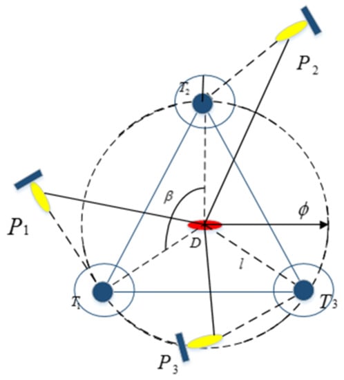
Figure 10.
Distribution of potential points in the process of hunting.
Here, is the origin of polar coordinates, is the polar angle, and the heading direction of the target is taken as the polar axis. The polar angles of the current positions of each hunter are calculated and then sorted from smallest to largest as , in terms of their polar angles. After sorting, the elements in and sequentially correspond to achieve the optimal assignment of tasks, as follows:
where T is the set of the potential hunting positions.
A virtual hunting circle and hunting potential point are formed immediately by the AUV that finds the target, and the information is sent to other AUVs in the environment. Each AUV with a decision-making mechanism decides whether to participate in hunting or not and sends the message back to the organizer. This creates a joint contractual relationship between the hunting members. In this way, the task assignment and role switching of AUVs can be described as the change process of the validity and invalidation of the hunting contract. The specific decision-making mechanism requirements are as follows:
- (1)
- If an AUV fails to reach a predetermined position within the time limit after it has been identified as a hunting actuator, the contract becomes invalid and the role is changed;
- (2)
- If the required cooperative hunting executors do not all reach the corresponding potential point within the time limit, the contract is re-established;
- (3)
- After the target is destroyed, the contract becomes invalid immediately. The initiator of the hunting shall send the message of giving up to other executors in the team for role switching;
- (4)
- When the initiator gives up, a message is sent to the other executors about the success of the chase.
The following provisions shall be made in the assignment of tasks to decide whether or not to join the hunting contract:
- (1)
- In affirming a commitment to hunt for a target, all other mission roles of the executor in effect of the contract are waived;
- (2)
- All AUVs are required to exchange information before the hunting contract becomes effective. The role switch is abandoned when the AUV that is about to sign the hunting contract has confirmed that the team does not need it.
5. Simulation
5.1. Search Algorithm Verification
By comparing the search results with the random method and the scan line method, this paper verified the high efficiency of the DDPC search algorithm. The experiments were run on a computer with an AMD Ryzen 5 4600H CPU at 3.00 GHz and 16.00 GB RAM.
Three AUVs were set in the simulation environment with 30 random static targets and obstacles with different shapes and positions. The simulation was set to compare the final target search results of each algorithm in 1000 time steps. Each target is marked after it is found by an AUV. The final experimental results of the three methods are displayed below. Figure 11 shows the target search method proposed in this paper, where there are still four targets left to be searched for after the deadline. Figure 12 shows the results of the random search method. Each AUV sailed randomly in the environment, and 16 static targets were found within the specified time. Figure 13 shows that the scan line method failed to cover the whole search environment smoothly and efficiently and 22 static targets were found within the specified time.
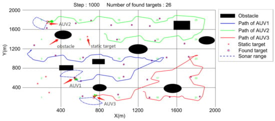
Figure 11.
DDPC search.
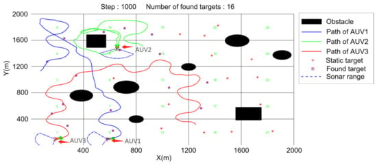
Figure 12.
Random search.
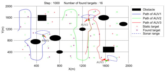
Figure 13.
Scan line search.
After the program runs for 1000 time steps, two indicators are counted to measure the target search conditions under different methods, respectively:
- (1)
- Regional coverage;
- (2)
- Average number of found targets.
The indexes respectively describe the ratio of the regions searched by the AUVs in a certain task time to the whole environment and the number of targets searched for by the AUVs. The specific formula is shown in (51).
Figure 14 indicates that the method proposed in this paper can better cover almost all task areas within the specified task time, followed by the scan line method. Due to its unique search method, the scan line method can cover every region it passes through. If the task time is long enough, the scanning line method can achieve full area coverage. However, the heading of the AUV of the random search method is random at each time point, so there are repeated searches in the same area, or it arrives at a certain sub-area and then leaves quickly, so the coverage rate also decreases. It can be seen from the data statistics that the coverage rate of the random search method is also the lowest.
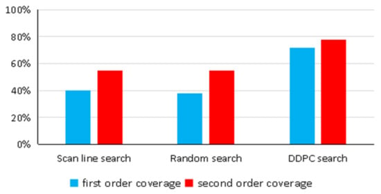
Figure 14.
Regional coverage.
In order to explore the influence of the prediction on the algorithm, we compared the influence of different prediction steps on the average computation time of each step and the detection rate of the target after 1500 search steps for 30 static targets, as shown in Figure 15. According to the data in the figure, we chose the predicted steps to be 10.
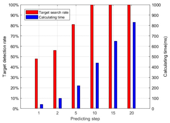
Figure 15.
The influence of different prediction steps on the performance of the Algorithm.
5.2. Hunting Algorithm Verification
In this section, four AUVs and two dynamic targets were set up in the environment to prove the validity of the hunting algorithm. At first, the AUVs were searching in different areas, as shown in Figure 16. Figure 17 shows that AUV 1 found the target and organized the other two AUVs to go to the hunting potential point while the fourth AUV was still searching. As can be seen in the figure, AUV 1 was already at the hunting potential point, while the other 2 AUVs were still heading towards the assigned positions. The formation of the hunt was created as shown in Figure 18. Figure 19 shows that after the dynamic target was destroyed, the formation disbanded and the search mission continued.
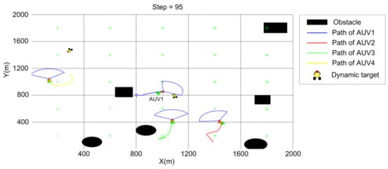
Figure 16.
T = 95 (steps).
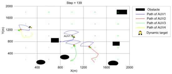
Figure 17.
T = 139 (steps).
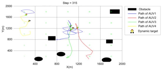
Figure 18.
T = 315 (steps).
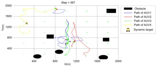
Figure 19.
T = 567 (steps).
5.3. Cooperative Searching and Hunting Simulation
In order to prove the feasibility and effectiveness of the searching and hunting method proposed in this paper, the simulation environment was set to be a two-dimensional area of 2000 m × 2000 m, and the AUV was set to perform the target search and hunting task at a fixed depth in the horizontal plane. In the simulation environment, the speed of AUV as set at a constant 4 m/s while searching and accelerated to 5 m/s when executing the hunting mission. The maximum angular velocity of turning was . The detection performance parameters of forward-looking sonar were , , and . Global communication was considered, obstacles with different shapes were set, and 40 static targets with random positions and 2 dynamic targets with different tracks were set in the simulation environment with obstacles in different shapes. There are 2 dynamic targets and 40 static targets set in the Environment, as shown in Table 2 and Table 3. Six AUVs were launched at the position according to Table 4 to perform the target search task with a specified running time of T = 2000 (steps). The operation scenario of the target search is shown in the figures below:

Table 2.
Dynamic target position.

Table 3.
Static target position.

Table 4.
AUV position.
In the simulation experiment, the process of multi-AUV task execution at different times was selected. As can be seen from the figure, six AUVs marked static targets when they found them and maintained the formation to hunt and destroy dynamic targets.
Figure 20, Figure 21, Figure 22, Figure 23 and Figure 24 show the process of two dynamic targets being hunted and destroyed. Figure 21 shows that AUV 1 finds dynamic target 1 and then organizes the other two AUVs to hunt according to the target hunting algorithm. However, AUV 3 and AUV 5 are performing a target search. When they become hunting executors, they abandon the current search task and accelerate their movement towards the hunting potential point. After moving target 1 is hunted, AUV 5 found dynamic target 2. AUV 3 and AUV 4, which are not performing the hunting task at this time, become members of the new team and hunt the moving target. When encountering obstacles, the AUV switches to obstacle avoidance mode and does not return to hunting mode until obstacles no longer appear in the view of forward-looking sonar. Each team eventually forms as a triangle formation and maintains the search for a while before the dynamic target is finally destroyed, as shown in Figure 22 and Figure 23. After the hunting formation is disbanded, the target search is carried out again until the time limit is reached or all the targets are searched. Figure 24 shows the final result. Therefore, the effectiveness of the method can be proved and dynamic targets can be successfully hunted.
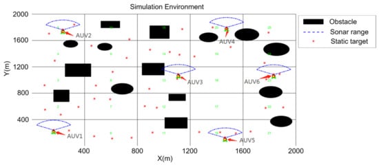
Figure 20.
Initialization of simulation environment.
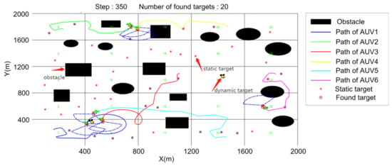
Figure 21.
T = 345 (steps).
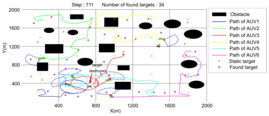
Figure 22.
T = 711 (steps).
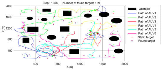
Figure 23.
T = 1358 (steps).
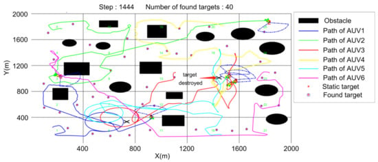
Figure 24.
Final experimental result.
6. Conclusions
For the first time, dynamic prediction and online optimization decision-making are conducted based on the environmental region state and AUV state to solve the problem of multi-AUV cooperative searching and hunting. This algorithm divides the large-scale unknown environment faced by the AUV into two-level search sub-regions and establishes a mathematical model. Based on the distributed search theory, the AUV state model and the regional state information update mechanism are introduced. The predicted region state information and AUV input state are obtained through the time window rolling optimization model, and the online optimization decision function is used to solve the regional and AUV state update input, and finally, the purpose of the multi-AUV collaborative target search us realized. When the AUV finds a dynamic target, it hunts the dynamic target and destroys it. Combined with the traditional hunting organization method, a dynamic distribution hunting method is proposed to reasonably allocate the hunting potential points of the moving target so that the AUV can form a hunting formation more quickly. Finally, the simulation verification of the multi-AUV cooperative target searching and hunting is given, which proves the effectiveness of the method.
Because the actual unknown underwater environment is more complex, there are still many problems and deficiencies in the research content that need to be improved in the future, including the following:
- (1)
- Communication delay and loss of information;
- (2)
- Complex groups of dynamic obstacles;
- (3)
- Dynamic targets with multiple motion states;
- (4)
- Application in the 3D underwater environment.
Author Contributions
Conceptualization, J.L. and C.L.; methodology, J.L.; software, J.L.; validation, J.L. and C.L.; formal analysis, J.L.; investigation, J.L. and C.L.; resources, J.L.; data curation, H.Z.; writing—original draft preparation, J.L.; writing—review and editing, J.L. and C.L.; visualization, H.Z. and C.L.; supervision, J.L.; project administration, J.L.; funding acquisition, J.L. All authors have read and agreed to the published version of the manuscript.
Funding
This search work was funded by the National Natural Science Foundation of China, grant no. 5217110503 and no. 51809060 and the Research Fund from Science and Technology on Underwater Vehicle Technology, grant no. JCKYS2021SXJQR-09.
Institutional Review Board Statement
Not applicable.
Informed Consent Statement
Not applicable.
Data Availability Statement
Not applicable.
Conflicts of Interest
The authors declare no conflict of interest.
References
- Wu, B.; Saigol, Z.; Han, X.; Lane, D. System Identification and Controller Design of a Novel Autonomous Underwater Vehicle. Machines 2021, 9, 109. [Google Scholar] [CrossRef]
- Li, J.; Zhai, X.; Xu, J.; Li, C. Target Search Algorithm for AUV Based on Real-Time Perception Maps in Unknown Environment. Machines 2021, 9, 147. [Google Scholar] [CrossRef]
- Liu, Y.; Wang, M.; Su, Z.; Luo, J.; Xie, S.; Peng, Y.; Pu, H.; Xie, J.; Zhou, R. Multi-AUVs Cooperative Target Search Based on Autonomous Cooperative Search Learning Algorithm. J. Mar. Sci. Eng. 2020, 8, 843. [Google Scholar] [CrossRef]
- Sun, A.L.; Cao, X. A Fuzzy-Based Bio-Inspired Neural Network Approach for Target Search by Multiple Autonomous Underwater Vehicles in Underwater Environments. Intell. Autom. Soft Comput. 2021, 27, 551–564. [Google Scholar] [CrossRef]
- Yao, P.; Qiu, L.Y. AUV path planning for coverage search of static target in ocean environment. Ocean Eng. 2021, 241, 110050. [Google Scholar] [CrossRef]
- Yue, W.; Guan, X. A Novel Searching Method Using Reinforcement Learning Scheme for Multi-UAVs in Unknown Environments. Appl. Sci. 2019, 9, 4964. [Google Scholar] [CrossRef] [Green Version]
- Luo, C.; Yang, X. A bioinspired neural network for real-time concurrent map building and complete coverage robot navigation in unknown environments. IEEE Trans. Neural Netw. 2008, 19, 1279–1298. [Google Scholar] [CrossRef]
- Cai, Y.; Yang, S. An improved PSO-based approach with dynamic parameter tuning for cooperative multi-robot target searching in complex unknown environments. Int. J. Control 2013, 86, 1720–1732. [Google Scholar] [CrossRef]
- Dadgar, M.; Jafari, S. A PSO-based multi-robot cooperation method for target searching in unknown environments. Neurocomputing 2016, 177, 62–74. [Google Scholar] [CrossRef]
- Saadaoui, H.; Bouanani, F.E. Information Sharing Based on Local PSO for UAVs Cooperative Search of Unmoved Targets. In Proceedings of the International Conference on Advanced Communication Technologies and Networking, Marrakech, Morocco, 2–4 April 2018. [Google Scholar]
- Wu, C.; Ju, B. UAV Autonomous Target Search Based on Deep Reinforcement Learning in Complex Disaster Scene. IEEE Access 2019, 7, 117227–117245. [Google Scholar] [CrossRef]
- Ivić, S.; Crnković, B.; Arbabi, H.; Loire, S.; Clary, P.; Mezić, I. Search strategy in a complex and dynamic environment: The MH370 case. Sci. Rep. 2020, 10, 19640. [Google Scholar] [CrossRef] [PubMed]
- Wang, Y.; Hong, B. Cooperative Multiple Mobile Targets Capturing Algorithm for Robot Troops. J. Xi’an Jiaotong Univ. 2003, 37, 573–576. [Google Scholar]
- Wang, H.; Wei, X. Research on Methods of Region Searching and Cooperative Hunting for Autonomous Underwater Vehicles. Shipbuild. China 2010, 51, 117–125. [Google Scholar]
- Meng, X.; Sun, B. Harbour protection: Moving invasion targrt interception for multi-AUV based on prediction planning interception method. Ocean Eng. 2021, 219, 108268. [Google Scholar] [CrossRef]
- Cao, X.; Xu, X.Y. Hunting Algorithm for Multi-AUV Based on Dynamic Prediction of Target Trajectory in 3D Underwater Environment. IEEE Access 2020, 8, 138529–138538. [Google Scholar] [CrossRef]
- Kapoutsis, A.; Chatzichristofis, S. DARP: Divide Areas Algorithm for Optimal Multi-Robot Coverage Path Planning. J. Intell. Robot. Syst. 2017, 86, 663–680. [Google Scholar] [CrossRef] [Green Version]
- Shojaei, K.; Arefi, M. On the neuro-adaptive feedback linearising control of underactuated autonomous underwater vehicles in three-dimensional space. IET Control Theory A 2015, 9, 1264–1273. [Google Scholar] [CrossRef]
- Zhao, S.; Lu, T. Automatic object detection for AUV navigation using imaging sonar within confined environments. In Proceedings of the IEEE Conference on Industrial Electronics & Applications, Xi’an, China, 25–27 May 2009. [Google Scholar]
- Zhou, G.; Wu, L. Constant turn model for statically fused converted measurement Kalman filters. Signal Process. 2015, 108, 400–411. [Google Scholar] [CrossRef]
- Zeigler, B.P. High autonomy systems: Concepts and models. In Proceedings of the Simulation and Planning in High Autonomy Systems, Tucson, AZ, USA, 26–27 March 1990. [Google Scholar]
- Wu, L.; Niu, Y.; Zhu, H. Modeling and characterizing of unmanned aerial vehicles autonomy. In Proceedings of the 9th World Congress on Intelligent Control and Automation, Jinan, China, 6–9 July 2010. [Google Scholar]
Publisher’s Note: MDPI stays neutral with regard to jurisdictional claims in published maps and institutional affiliations. |
© 2022 by the authors. Licensee MDPI, Basel, Switzerland. This article is an open access article distributed under the terms and conditions of the Creative Commons Attribution (CC BY) license (https://creativecommons.org/licenses/by/4.0/).