Abstract
Single-port minimally invasive surgery requires only a single incision, which further reduced intraoperative bleeding, reduced postoperative pain, and improved cosmetic benefits. However, the cooperative operation of multiple surgical instruments and forming an effective workspace under a single micro-incision remain a great challenge. This paper proposes a new type of manual training platform for single-port minimally invasive surgery. The designed surgical instrument imitates the structure of a human arm. The proximal end of the instrument is deployable structures (such as shoulder joint and elbow joint); they form an operating space and provide stable support for the instrument after deployed. In addition, the distal end of the instrument is a flexible instrument (such as a human hand), to realize posture adjustment and perform surgical operations. The surgical instrument implements a series of synergistic movements from placement, deployment, adjustment, and recovery. In addition, the platform includes a retightening force adjusting mechanism for the tendon-driven method and a quick-change mechanism for surgical instruments. A series of experiments on a functional prototype have validated the effectiveness and reliability of the designed platform. It can be convenient for doctors to practice master–slave single-port surgical instruments in a variety of environments.
1. Introduction
Robot-assisted minimally invasive surgery (RMIS) adopts an operating mode that features cooperation between surgical instruments and robotic arms. This not only liberates doctors from the operating table, but also enhances their hand-eye coordination of doctors and improves the accuracy of operation [1,2,3]. As surgical methods are evolving to become minimally invasive, multi-port RMIS is also gradually moving to single-port RMIS. The reduction in surgical incisions can further reduce the incidence of infection and improve the cosmetic effect of wounds [4,5,6,7].
However, unlike multi-port minimally invasive surgery (MIS), single-port MIS requires three to four surgical instruments to be operated through a single incision. Limited by the space constraint of a single incision, the intersection point of surgical instruments is moved from the lesion to the incision, resulting in the operation mode of surgical instruments in single-port MIS no longer following the mapping law of traditional MIS. In addition, due to the change in the approach of surgical instruments in single-port MIS, the surgical instruments and endoscope enter the patient’s body in a parallel posture, making it difficult to create an adequate surgical triangulation between the instruments.
To solve the problem of inadequate triangulation of single-port RMIS, researchers have achieved a flexible design for surgical instruments, adopting rigid-flexible configuration. Kobayashi et al. [8,9] and Bai et al. [10,11] designed surgical instruments based on a double screw-drive mechanism, which have a good load capacity, but limited endoscopic field of vision, and an insufficient range of instrument movement. The ViaCath surgical robot [12] uses a pair of articulated manipulators and has been successfully used in clinical trials in the treatment of atrial fibrillation and renal calculi [13]; however, the instruments lack spatial positioning in vivo, and the range of motion of the end-effectors is small. Phee et al. designed a dual-arm endoscopic robot for gastrointestinal endoscopic procedures [14,15], but the workspace of this instrument is also small. These instruments extend a pair of end-effectors at the distal endoscopic position, which is used for surgical operations, but the instruments’ workspace and endoscopic field of vision are limited and are only suitable for a specific type of surgery. In addition, continuum manipulators have been a hot research topic in recent years. They have excellent accessibility, agility, and miniaturization [16,17,18,19,20]. However, they have limitations in terms of their high stiffness and payload capacity.
Studies have also been conducted on the use of a deployable structure, which provides triangulation for a pair of surgical instruments by deploying a certain angle. Simaan et al. developed the IREP single-port surgical robot [21,22]; the system integrated a pair of continuum instruments and an endoscope that can be deployed and operated and can recover the instruments through 21 joints. However, the load capacity of the surgical instrument is low, and the operation is difficult. The HVSPS surgical robot [23] developed by the Technical University of Munich also has a pair of surgical instruments and an endoscope, but its approach is limited. The SPRINT system [24,25] designed by Dario et al. uses a pair of rigid connecting rods in series to complete the deployment of surgical instruments. The load capacity of the end-effector is up to 5N and the range of motion is large, but the endoscope and instruments need to be placed one by one, and the operation procedure is tedious. These instruments expand at a certain angle through rigid joints to form an operating space for a pair of manipulators, but it is difficult to strike a balance between flexibility, maneuverability, and approach.
Integrating multiple surgical instruments into a mechanical arm is a type of single-port RMIS mode that is commercially available at present. The da Vinci SP robotic surgical system was FDA approved in 2018 [26,27]; however, the applicability of this system is limited due to the suboptimal load capacity and range of motion of the surgical instruments. In addition, the SPORT surgical system designed by Titan Medical Inc. [28] and the SURS [29] developed by Xu et al. both adopt the method of integrating a pair of independent flexible instruments into a single tube. Although these surgical instruments are highly flexible, the operating space is small, and the volume of the external part of the patient is large and complex.
In this paper, a single-port MIS manual training platform, which includes a pair of flexible instruments and an endoscope, is designed for single-port MIS. The endoscope is adjusted by a networked computer, and the surgical instruments are controlled by a pair of joystick controllers. The designed surgical instrument imitates the structure of the human arm. The proximal end of the instrument is made up of deployable structures (such as shoulder joint and elbow joint), that form an operating space and provide stable support for the instrument after deployment. The distal end of the instrument is a flexible end-effector (such as a hand) that realizes posture adjustment and performs surgical operations. The surgical instrument implements a series of synergistic movements from placement, deployment, adjustment, and recovery, and provides high load capacity and high flexibility.
The single-port MIS training platform designed in this paper aims to simulate the environment of single-port MIS, helping doctors to familiarize themselves with single-port operations, and providing an effective surgical instrument for single-port MIS. In addition, the platform includes a retightening force adjusting mechanism for the tendon-driven method and a quick-change mechanism for surgical instruments. Finally, the simulated operation experiment is successfully realized by using the prototype, verifying the feasibility and effectiveness of the designed single-port surgical instrument.
2. Materials and Methods
The instrument for single-port MIS designed in this paper used a combination of joint deployment and multi-joint surgical instruments. It employed a multi-articulated structure to achieve a flexible end-effector and an articulated structure to provide stable support for the instrument. By combining the advantages of the two types of structures, the goal of flexible operation in single-port MIS was achieved. The single-port MIS training platform presented here comprises an instruments tube, a cord conveyor, a tensioner, and a pair of controllers. Figure 1 provides an overview of the single-port MIS training platform.
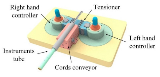
Figure 1.
Overview of the designed single-port MIS training platform.
2.1. Instrument Tube
A surgical instrument tube is an executive mechanism that contains a pair of flexible surgical instruments and a laparoscope. The design difficulty of the single-port surgical instrument was to realize the operation of its deployment and recovery, and to ensure its stability and motion accuracy. The designed surgical instrument in this paper was inspired by the structure of the human arm. Based on the segmented structure of the arm, the surgical instrument is divided into four segments (Figure 2a). The first three segments correspond to the hand, forearm, and big arm, respectively, and segment IV is used for the installation of the instrument and cord docking.
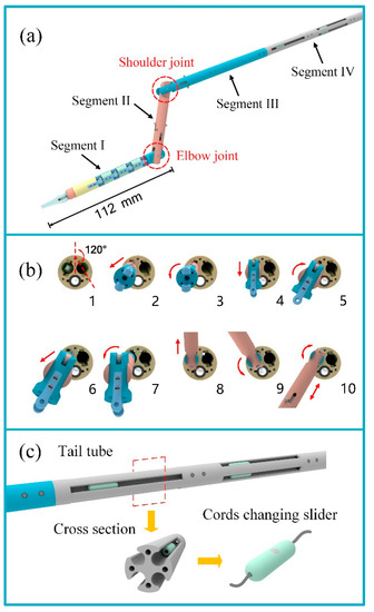
Figure 2.
The design of the instrument tube. (a) structure diagram of the surgical instrument; (b) unfolding process of the articulated arm; (c) schematic diagram of the tail tube structure.
Segment I of the surgical instrument is the flexible instrument, which corresponds to the hand, and is the execution part of all surgical operations. The flexible instrument used in this paper is a “snake-like” surgical instrument (the introduction of the flexible instrument is described in detail in a previously published paper [30]). It has four DOFs of movement: opening and closing motions of the forceps, rotation of the forceps, and bi-directional bending of the instrument. Considering that the deformation process of the instrument in the body may scratch an organ and tissue, the flexible part of the end of the instrument is appropriately shortened based on the original size.
Segments II and III of the surgical instrument correspond to the forearm and big arm respectively, and the rotation joints of the two articulated arms correspond to the elbow and shoulder joints of the arm. After the instrument tube enters the patient’s body through a single-port, Segments II and III carry out related movements to make the surgical instrument deformed and fixed, thus forming a stable working triangle. Similarly, at the end of the operation, the instruments are restored to a straight line and returned to the instrument tube to complete the recovery of the instruments. The bending of Segments II and III adopts the push–pull structure of the curved rod, and the joints are locked by a slot. To take one of the surgical instruments as an example, the deployment process of Segments II and III is shown in Figure 2b, and the specific process is listed in Table 1.

Table 1.
The unfolding process of the articulated arm.
The tail tube is the connecting part between the surgical instrument and the cords conveyor. It has a long length to ensure that the surgical instrument has enough linear motion. In addition, because the surgical instruments use a tendon-driven method, eight cord connection sliders (one for each cord) are uniformly added to the tail tube along the axis to facilitate the maintenance of surgical instruments or the replacement of cords.
To facilitate the timely inspection and replacement of broken cords, the platform adopts the design of a segmented layout of cords. The cord is divided into three sections: one is arranged in the instrument tube, another is arranged in the cords conveyor and the tensioner, and the other is arranged in the controller, and the cords are connected by the cord connection slider.
The cord connection slider (Figure 2c) is a hollow cylinder that can be split into two equal parts. The two cords are respectively pierced through holes on both sides of the cord connection slider and knotted and fixed in the inner cavity. The segmented design of the cords not only facilitates the rapid inspection and replacement of a cord when it is worn or broken, but also facilitates the rapid installation, removal, and storage of the surgical instrument as a whole.
The surgical instrument tube consists of a pair of flexible surgical instruments and a laparoscope, and its workflow is shown in Figure 3. Combined with the introduction of each section of the surgical instrument in the above, the working process of the surgical instrument tube is listed in Table 2.
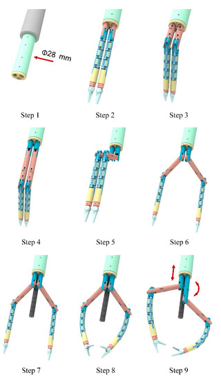
Figure 3.
Workflow of the surgical instrument tube.

Table 2.
Workflow of the surgical instrument tube.
As mentioned above, each surgical instrument has six DOFs and two adjusting joints. The end-effector of the instrument has a maximum opening angle of 120° and a rotation movement of ±180°, the length of the flexible instrument is 112 mm, and its maximum bending angle reaches 72°. When the instrument tube changes to the working state, the workspace of the surgical instrument is solved according to the kinematics and inverse kinematics method, which is approximately the superposition of two hemispheres, as shown in Figure 4.
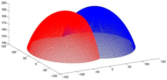
Figure 4.
Workspace of a pair of flexible surgical instruments.
2.2. Cords Conveyor and Tensioner
The cords conveyor is used to install the surgical instrument tube and provides the length supply for the cords for the surgical instruments during the linear motion. On the other hand, the cords conveyor is adjacent to the tensioner, which transfers the cords passed from the surgical instrument to the tensioner. The structure of the cords conveyor is shown in Figure 5a. It has two symmetrical parts, and each part corresponds to a surgical instrument. When the surgical instrument moves forward or backward, the pulley in the cords conveyor moves along the chute to output or retract cords for the surgical instrument.
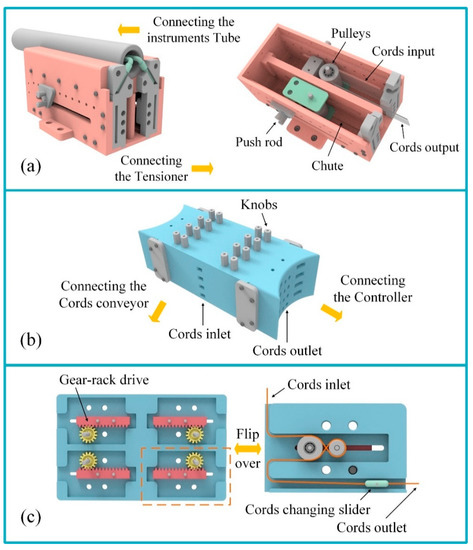
Figure 5.
Structure of cords conveyor and tensioner: (a) the cords conveyor; (b) the tensioner; (c) schematic diagram of the tensioning module structure.
Surgical instruments have large aspect ratio characteristics, so the use of the tendon-driven method has become an efficient and reliable driving type. However, the cords require regular pre-tensioning to ensure the efficiency of power transmission and movement accuracy of the surgical instruments. To prolong the use of surgical instruments, the single-port MIS training platform designed in this paper has a tensioner module added, combined with a segmented cord design, which makes it convenient for doctors to pre-tighten each cord when preparing for surgery.
The tensioner (Figure 5b) is adjacent to the cords conveyor. When cords are drawn from the cords conveyor, they are introduced in the inlet on the front face of the tensioner, and are finally drawn from the outlet on the side. The tensioner is composed of four layers of tensioning modules, and each layer introduces four cords. The tensioning module consists of a pair of rack and pinions, and a pulley is fixed under the rack (Figure 5c). The cord follows the slot on each layer and bypasses the pulley. When turning the knob on the surface of the tensioner, the gear shaft drives the gear to rotate, and the rack and pulley move along the chute until the cord achieves the pre-tightening effect. In addition, the cords connection slider is arranged in the straight segment of the slot, which is the same as the tail tube portion of the surgical instrument. The third section of the cord in the platform is from the cords connection slider of the tensioner to the controller.
2.3. Controller
The control section is another important part of the MIS training platform, in addition to the surgical instruments and the vision system. In order to facilitate use, the designed mechanical controller is integrated into the platform. The controller is a pair of main manipulators with a joystick structure, which is used to control the six DOFs of the surgical instruments. The upper part of the main manipulator is a joystick, and the lower part is a transmission base (Figure 6a). The diameter of the joystick is 38 mm and the height is 100 mm, making it convenient for doctors to hold with one hand. When in use, first the joystick lock is removed, and then the joystick is held by hand. The joystick can swing in any direction under the push and pull of the hand, and the swing of the joystick corresponds to the bending movement of the flexible instrument. For example, when the joystick is pushed forward, the flexible instrument bends upward, and when the joystick swings to the right, the flexible instrument also bends to the right. In addition, two knobs are arranged side by side on the joystick, respectively corresponding to the opening and closing motion and the rotation motion of the end-effector.
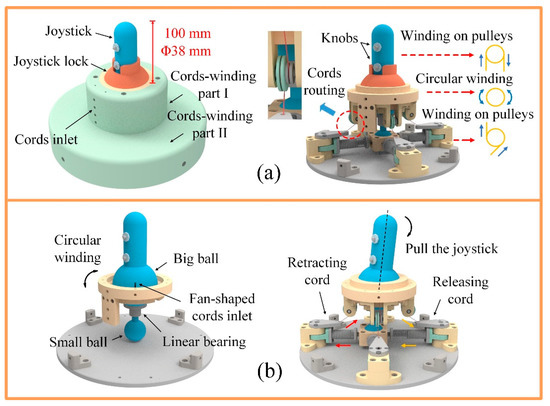
Figure 6.
Schematic diagram of the controller structure: (a) schematic diagram of the cords routing in the controller; (b) design of control structure for the bending movement of surgical instruments.
The third section of the cords drawn from the tensioner is introduced from the inlet of the controller. Eight cords introduced into the controller are divided into two parts (Figure 6a). After a circular winding in cords-winding part I, four of the cords enter the inside of the big ball from the four fan-shaped cords inlets on the outside of the big ball; they then pass through the center of the big ball and wind up onto the pulleys in the joystick, as shown in Figure 6b. When turning the knob on the joystick, the pulley drives the cord to complete the action of retracting on one side and releasing on the other side, in order to realize the opening and closing or the rotation of the end-effector. It should be pointed out that the knob is designed with a self-locking structure to ensure that the end-effector maintains its state of action. After a circular winding in cords-winding part I, the other four cords are wound down on pulleys of the cords-winding part II, after passing through the pulleys of the cords-winding part I. Swinging the joystick will drive the big ball to rotate around the ball center, and the small ball will move in the horizontal plane driven by the linear bearing, which is fixed directly below the big ball, changing the length of the cord in the corresponding direction through the compression spring and slide rail, to realize the bending movement of the end-effector of the flexible instrument.
3. Results
3.1. Parameter Optimization of the Tendon-Driven Method
Surgical instruments for RMIS generally use the tendon-driven method to achieve power transmission under the structure of a large length diameter ratio. Due to the nonlinear characteristics of the cord and the tension change of the cord before and after the guide pulley in the process of cord transmission, there are some phenomena such as hysteresis and clearance in the transmission process [31,32] that adversely affect the accuracy of surgical instruments. Therefore, it is necessary to control the tension change of the cords transmission system of the surgical instrument to ensure the consistency and accuracy of the movement of the end effectors of surgical instruments.
According to the structural characteristics of the surgical instrument, the influence on the change of cord tension is analyzed from four aspects: the radius ratio of the guide pulley and the cord, the wrap angle of the cord on the guide pulley, the friction coefficient, and the tension inclination angle. To quantitatively analyze the influence of the above structural parameters on the change of cord tension, the cord tension required to drive the manipulator at the end of the surgical instrument is defined as input tension T1, and its value is set to 1. The cord tension output by the instrument gearbox is defined as output tension T2. The higher the value of T2, the greater the tension loss of the cord.
To analyze the effect of the friction coefficient and the wrap angle on the tension loss, output tension T2 was tested under different friction coefficients and wrap angles. The friction coefficient depends on the material of the cord and the guide pulley. The cords used in surgical instruments are generally 304 stainless steel, and the guide pulleys are normally made of steel, copper, cast iron, and powder metallurgy. Therefore, according to the friction coefficient between the cord and the above-mentioned different guide pulley materials, the friction coefficients μ = 0.15, 0.25, 0.35, and 0.50 are taken respectively in the verification process. Furthermore, the wrap angle θ of the cord on the guide pulley ranges from 0° to 180°. As shown in Figure 7, the tension loss on the cord increases obviously with the increase in the wrap angle, and the larger the friction coefficient μ, the more the tension loss. Therefore, the friction coefficient between the cord and the guide pulley, and the wrap angle of the cord on the guide pulley should be reduced as much as possible. In addition, according to the research on the fatigue life of wire rope by the Association of German Engineers (VDI), the fatigue life of wire rope decreases sharply when the wrap angle is 10°–50°. Therefore, when designing the wrap angle of surgical instrument cords, while reducing the wrap angle, a wrap angle within the range of 10°–50° should be avoided.
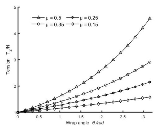
Figure 7.
The change of output tension T2 with the wrap angle under different friction coefficients.
Due to the structural size limitation of surgical instruments (the radial dimension of an operating rod and end-effector is generally not greater than 10 mm), the radius ratio of the guide pulley and the cord is usually less than 40 [33]. Therefore, to analyze the influence of the radius ratio k of the guide pulley on the cord, the values of the radius ratio k were selected as 40, 20, 10, and 5, and output tension T2 was tested under the different radius ratios k. As shown in Figure 8, the tension loss of the cord increases with the increase in radius ratio k. Therefore, to reduce the tension change of the cord, the radius ratio k should be reduced as much as possible; that is, the diameter of the guide pulley should be reduced as much as possible. However, if the radius ratio k is too small, the bending stress of the cord will be increased, which can easily lead to fatigue breakage of the cord. Therefore, the diameter of the guide pulley should be reduced as much as possible in the design, and the bending stress of the cord should be checked at the same time.
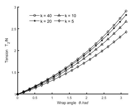
Figure 8.
The change of output tension T2 with different radius ratios.
To avoid the problem of discontinuous contact between the cord and guide pulley, the range of tension inclination angle ω should be limited to ω < π/2 [34]. In addition, to avoid the relaxation of the cord, the cord needs a certain pre-tightening force. Therefore, the tension inclination angle ω is generally small. To analyze the influence of the tension inclination angle on the cord tension, tension inclination angles ω = 20°, 10°, 5°, and 0° were taken respectively in the verification process. As shown in Figure 9, output tension T2 increases with the increase in tension inclination angle. This is because the larger the tension inclination angle, the larger the bending stiffness EI of the cord. According to the moment of inertia formula, I = π d4/64, where d is the diameter of the cord. Therefore, to reduce the influence of the tension inclination angle, a cord with a smaller diameter should be selected as far as possible in order to satisfy the structural requirements and transmission tension.
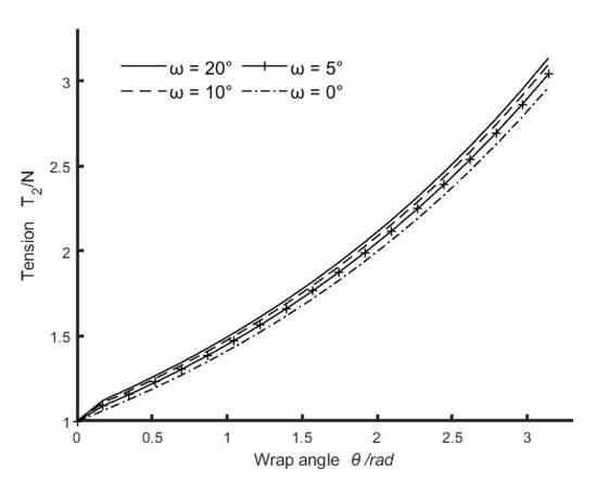
Figure 9.
The change of output tension T2 with different tension inclination angles.
3.2. Prototype
A prototype of the single-port MIS training platform was produced after the optimization of the structural parameters of the transmission system to verify the proposed design. The prototype was manufactured using a combination of machining and 3D printing, and an Ni-Ti alloy cord with a diameter of 0.45 mm was selected as the transmission cord for the surgical instruments. First, each part was assembled separately (Figure 10a–d), and the instrument tube was then connected with the cords conveyor, the tensioner, and the controller. Finally, the pre-tensioning adjustment of each cord was completed through the tensioner.
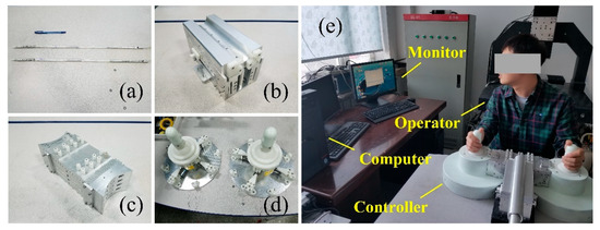
Figure 10.
The prototype of the single-port MIS training platform: (a) instruments tube; (b) cords conveyor; (c) tensioner; (d) controllers; (e) operation the prototype of the platform.
3.3. Experiments
A series of experiments were carried out to evaluate the functionality of this platform and the movements of the surgical instrument. The experiments verified that the instruments tube can perform the unfolding deformation and recovery operation, and the controller and the surgical instrument can achieve a one-to-one mapping relationship. In addition, some further experiments were carried out on the platform using the MIS simulation training module, including ball capture, steel wire curve perforation, and suture operation.
A ball capture test is used to verify the clamping and pulling operation of the surgical forceps, as well as the flexibility and accuracy of the surgical instruments. Before the test, put the base plate on the table, and place a yellow, a pink, and a green ball in the transparent container. First, move the surgical instrument over the transparent container, open the surgical forceps, and grab the yellow ball through the cylindrical hole of the ball. Then, lift the surgical forceps slowly and move them to the bracket attachment on the right side of the base plate. Finally, aim at a bracket, open the surgical forceps, and slide the ball into the bracket. Repeat the above process and put the pink and green balls on the brackets in turn. The experiment process is shown in Figure 11a.
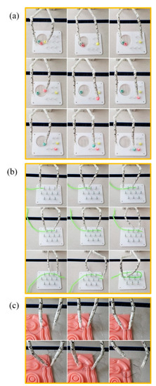
Figure 11.
Experiments on the platform: (a) single-port surgery system small ball picking test; (b) single-port surgical system snake-shaped perforation test; (c) suture operation test of single hole surgical system.
The perforation test is used to verify the coordination between two surgical instruments. Before testing, put the base plate on the table and place the green steel wire next to the base plate. First, move the left surgical instrument close to the steel wire and clamp it, and pull the steel wire near the first metal ring. Then, bend the surgical instrument so that the steel wire passes through the metal ring. Next, move the right surgical instrument between the first and second metal rings, and clamp one end of the steel wire. Subsequently, loosen the surgical instrument on the left, and move it toward the tail of the steel wire. Then, clamp the steel wire in the appropriate position, and bend the surgical instrument to deliver the steel wire into the metal ring until it passes through the second metal ring. Through the cooperative operation of the pair of surgical instruments, the steel wire is finally passed through the metal ring along the serpentine direction. The test process is shown in Figure 11b.
The suture operation is one of the most complex operations in surgery. In traditional single-port MIS, the position of the two surgical instruments is relatively close, it is difficult to form a working triangle, or the workspace of the surgical instruments is small, making it difficult to complete the suture operation. The suture operation test is used to verify the stability of the designed surgical instruments after they are deployed and deformed, to demonstrate the cooperation ability between the pair of the surgical instruments, and to test the output torque of the surgical forceps.
Before the test, place the suture simulation module on the table, and prepare a suture needle with thread. First, grasp the suture needle with the left surgical instrument, and slowly approach the long silicone wound. Turn the forceps so that the suture needle is inserted into the outside of the wound until the suture needle penetrates the wound. At this point, the needle is grasped with the right surgical instrument, and the surgical instrument is rotated to make the suture thread pass to the other side of the silicone wound. Move the left surgical instrument, clamp the suture needle, and turn back to the wound to perform the second suture operation. The test process is shown in Figure 11c. A total of four stitches were sutured in this test. Due to a lack of surgical operation experience, the width of the suture varies. Through this test, the cooperative effect of the surgical instruments is further verified, and it is proved that the surgical instruments of the single-port surgical system have sufficient workspace and operational stability, and that the surgical instruments have sufficient output torque. The complex surgical operation can be achieved.
4. Discussion
In this paper, a single-port MIS manual training platform is designed. The platform consists of four parts: an instruments tube, a cords conveyor, a tensioner, and a pair of controllers. The instrument tube comprises a pair of surgical instruments and an endoscope. As the part that is directly in contact with a patient’s lesion, the performance of the surgical instrument represents the quality of the operation platform. In addition to the performance of the surgical instruments, the comfort of the doctor when operating the surgical instruments is also important. Based on this, the designed surgical instrument imitates the structure of the human arm. The first section of the flexible instrument corresponds to the hand, and the bidirectional bending movement of the flexible instrument represents the wrist joint. The articulated joints of the second and third segments correspond to the forearm and the upper arm, and the expansion and fixation movements of the articulated joints represent the movement of the elbow joint and the shoulder joint. The cords conveyor ensures the length supply of the cords for the surgical instruments during the linear motion, and the tensioner ensures the transmission accuracy of the cords. They also play a role in connecting the instrument tube and the controllers. The controller adopts a joystick structure, which is simple, intuitive, and accurate to operate. In addition, the design of the surgical instruments makes use of joint deployment and a multi-joint structure, bringing six DOFs and two passive adjustment joints to the surgical instrument, which not only ensures its flexibility, but also provides enough workspace for the instrument. When a doctor controls the pair of surgical instruments, it is as if the doctor’s hands are operating, which greatly improves the experience of immersion in the operation.
According to the structural characteristics of surgical instruments, the effects of structural parameters such as radius ratio, wrap angle, friction coefficient, and tension inclination angle on the tension change of cords are analyzed. From the test results, the following conclusions can be drawn: the smaller the friction coefficient, the better; the smaller the wrap angle of the cord on the guide pulley, the better, and the interval of 10°–50° should be avoided; the smaller the radius ratio of the guide pulley and the cord, the better; when the radius of the cord is determined, the smaller guide pulley radius should be selected as far as possible, and the bending stress of the cord should be checked at the same time; and to reduce the influence of the tension inclination angle, a cord with a smaller diameter should be selected as far as possible on the premise of meeting the structural requirements and transmission tension. Through these conclusions, the relevant structural parameters of the platform are optimized.
Due to the manual control mode of the platform, the routing distance of the cords is long and the winding path is complex. In addition, a total of 16 cords are used to drive a pair of surgical instruments, which further increases the possibility of wear and fracture of the cords. To facilitate the timely inspection and replacement of broken cords, this platform adopts a segmented layout design of cords. The cords are divided into three sections: one is arranged in the instrument tube, another is arranged in the cords conveyor and the tensioner, and the other is arranged in the controller, with the cords connected by the cords connection slider. The segmented cord design also facilitates the installation, use, disassembly, and storage of the platform. The series of experiments on the functional prototype have validated the effectiveness and reliability of the designed single-port MIS training platform, and the feasibility of the surgical instrument has been proved.
5. Conclusions
In this study, we proposed a new type of manual training platform for single-port minimally invasive surgery. The designed surgical instrument imitates the structure of a human arm. The proximal end of the instrument comprises deployable structures (imitating a shoulder joint and an elbow joint), forming an operating space and providing stable support for the instrument after deployment. In addition, the distal end of the instrument consists of a flexible instrument (imitating a human hand) that carries out posture adjustments and performs surgical operations. The surgical instrument implements a series of synergistic movements from placement, deployment, adjustment, and recovery. The platform includes a retightening force adjusting mechanism for the tendon-driven method and a quick-change mechanism for the surgical instruments. In addition to the mechanical design, extensive analyses and experiments were carried out. Kinematic models were derived and the reachable workspace of the instruments covered the entire target surgical area. Various factors affecting the accuracy of the cord transmission were analyzed, and the corresponding structural parameters in the transmission system were optimized. A series of experiments on a functional prototype have validated the effectiveness and reliability of the designed platform. The single-port MIS training platform presented in this paper will be great service to surgeons. The mechanized control mode maximizes the portability and economy of the platform. It can be convenient for doctors to practice master–slave single-port surgical instruments in a variety of environments.
Future work will be conducted to reduce the overall size of the platform and to minimize the diameter of the surgical instrument. The performance of the surgical instrument will be improved and a prototype of the surgical instrument using medical metal materials will be produced. Furthermore, this platform will be used for natural orifice transluminal endoscopic surgery (NOTES) research after appropriate modification, and further experiments including animal experiments with the guidance of an endoscope will be conducted.
Author Contributions
Conceptualization, X.J. and M.F.; methodology, M.F.; validation, Z.H. and J.Z.; formal analysis, Y.G.; investigation, Y.G.; resources, Z.H.; data curation, Y.L.; writing—original draft preparation, M.F.; writing—review and editing, X.J.; visualization, M.F.; supervision, Z.H. and J.Z.; project administration, X.J.; funding acquisition, Z.H. All authors have read and agreed to the published version of the manuscript.
Funding
This research was funded by the National Natural Science Foundation of China (Grant No. 51975241), the Opening Foundation of the State Key Laboratory of Digital Manufacturing Equipment and Technology (Grant No. DMETKF2021008), the Key R&D Project of Jilin Province Science and Technology Department (Grant No. 20200404150YY), and the Jilin province industrial technology research and development project (Grant No. 2019C048-3).
Institutional Review Board Statement
Not applicable.
Informed Consent Statement
Not applicable.
Data Availability Statement
Not applicable.
Acknowledgments
The authors thank the surgeons and medical staff of the Thoracic Surgery Department and Gastrointestinal Surgery Department of Jilin University First Hospital for their technical support.
Conflicts of Interest
The authors declare no conflict of interest.
References
- Troccaz, J.; Dagnino, G.; Yang, G.-Z. Frontiers of medical robotics: From concept to systems to clinical translation. Ann. Rev. Biomed. Eng. 2019, 21, 193–218. [Google Scholar] [CrossRef] [PubMed]
- Parisi, A.; Reim, D.; Borghi, F.; Nguyen, N.T.; Qi, F.; Coratti, A.; Cianchi, F.; Cesari, M.; Bazzocchi, F.; Alimoglu, O.; et al. Minimally invasive surgery for gastric cancer: A comparison between robotic, laparoscopic and open surgery. World J. Gastroenterol. 2017, 23, 2376–2384. [Google Scholar] [CrossRef] [PubMed]
- Pędziwiatr, M.; Małczak, P.; Pisarska, M.; Major, P.; Wysocki, M.; Stefura, T.; Budzyński, A. Minimally invasive versus open pancreatoduodenectomy—systematic review and meta-analysis. Langenbeck’s Arch. Surg. 2017, 402, 841–851. [Google Scholar] [CrossRef] [PubMed] [Green Version]
- Stavros, A.A.; García-Alamino, J.M.; Hajibandeh, S.; Hajibandeh, S. Single-incision surgery trocar-site hernia: An updated systematic review meta-analysis with trial sequential analysis by the minimally invasive surgery synthesis of interventions outcomes network (MISSION). Surg. Endosc. 2017, 32, 1–10. [Google Scholar]
- Evers, L.; Bouvy, N.; Branje, D.; Peeters, A. Single-incision laparoscopic cholecystectomy versus conventional four-port laparoscopic cholecystectomy: A systematic review and meta-analysis. Surg. Endosc. Other Interv. Tech. 2017, 31, 3437–3448. [Google Scholar] [CrossRef] [Green Version]
- Cianci, S.; Rosati, A.; Rumolo, V.; Alletti, S.G.; Uccella, S. Robotic single-port platform in general, urologic, and gynecologic surgeries: A systematic review of the literature and meta-analysis. World J. Surg. 2019, 43, 49. [Google Scholar] [CrossRef]
- Kaouk, J.H.; Stein, R.J.; Haber, G.P. Atlas of Laparoscopic and Robotic Single Site Surgery; Springer: New York, NY, USA, 2017. [Google Scholar] [CrossRef]
- Kobayashi, Y.; Tomono, Y.; Sekiguchi, Y.; Watanabe, H.; Toyoda, K.; Konishi, K.; Tomikawa, M.; Ieiri, S.; Tanoue, K.; Hashizume, M.; et al. A surgical robot with vision field control for single port endoscopic surgery. Int. J. Med. Robot. Comp. 2010, 6, 454–464. [Google Scholar] [CrossRef]
- Kobayashi, Y.; Sekiguchi, Y.; Noguchi, T.; Takahashi, Y.; Liu, Q.; Oguri, S.; Toyoda, K.; Uemura, M.; Ieiri, S.; Tomikawa, M.; et al. Development of a robotic system with six-degrees-of-freedom robotic tool manipulators for single-port surgery. Int. J. Med. Robot. Comp. 2015, 11, 235–246. [Google Scholar] [CrossRef]
- Bai, W.; Cao, Q.; Leng, C.; Cao, Y.; Fujie, M.G.; Pan, T. A novel optimal coordinated control strategy for the updated robot system for single port surgery. Int. J. Med. Robot. Comput. Assist. Surg. 2017, 13, e1844. [Google Scholar] [CrossRef]
- Bai, W.; Wang, Z.; Cao, Q.; Yokoi, H.; Fujie, M.G.; Yeatman, E.M.; Yang, G.Z. Anthropomorphic dual-arm coordinated control for a single-port surgical robot based on dual-step optimization. IEEE Trans. Med. Robot. Bion. 2022, 4, 72–84. [Google Scholar] [CrossRef]
- Abbott, D.J.; Becke, C.; Rothstein, R.I.; Peine, W.J. Design of an Endoluminal NOTES Robotic System. In Proceedings of the 2007 IEEE/RSJ International Conference on Intelligent Robots and Systems, 29 October–2 November 2007; pp. 410–416. [Google Scholar]
- Canes, D.; Lehman, A.C.; Farritor, S.M.; Oleynikov, D.; Desai, M.M. The future of NOTES instrumentation: Flexible Robotics and in vivo minirobots. J. Endourol. 2009, 23, 787–792. [Google Scholar] [CrossRef] [PubMed]
- Wang, Z.; Phee, S.; Lomanto, D.; Goel, R.; Rebala, P.; Sun, Z.; Trasti, S.; Reddy, N.; Wong, J.; Ho, K. Endoscopic submucosal dissection of gastric lesions by using a master and slave transluminal endoscopic robot: An animal survival study. Endoscopy 2012, 44, 690–694. [Google Scholar] [CrossRef] [PubMed]
- Phee, S.J.; Low, S.C.; Sun, Z.L.; Ho, K.Y.; Huang, W.M.; Thant, Z.A. Robotic system for no-scar gastrointestinal surgery. Int. J. Med. Robot. Comp. 2008, 4, 15–22. [Google Scholar] [CrossRef] [PubMed]
- Hwang, M.; Kwon, D.S. Strong continuum manipulator for flexible endoscopic surgery. Mech. IEEE/ASME Trans. Mechatron. 2019, 24, 2193–2203. [Google Scholar] [CrossRef]
- Conrad, B.L.; Zinn, M.R. Interleaved continuum-rigid manipulation: An approach to increase the capability of minimally invasive surgical systems. IEEE/ASME Trans. Mechatron. 2017, 22, 29–40. [Google Scholar] [CrossRef]
- Rajarshi, R.; Long, W.; Nabil, S. Modeling and Estimation of Friction, Extension, and Coupling Effects in Multisegment Continuum Robots. A joint publication of the IEEE Industrial Electronics Society and the ASME Dynamic Systems and Control Division. IEEE/ASME Trans. Mechatron. 2017, 22, 909–920. [Google Scholar]
- Gao, A.; Murphy, R.J.; Liu, H.; Iordachita, I.I.; Armand, M. Mechanical model of dexterous continuum manipulators with compliant joints and tendon/external force interactions. IEEE/ASME Trans. Mechatron. 2017, 22, 465–475. [Google Scholar] [CrossRef]
- Alambeigi, F.; Bakhtiarinejad, M.; Sefati, S.; Hegeman, R.; Iordachita, I.; Khanuja, H.; Armand, M. On the use of a continuum manipulator and a bendable medical screw for minimally invasive interventions in orthopedic surgery. IEEE Trans. Med. Robot. Bionics 2019, 1, 14–21. [Google Scholar] [CrossRef]
- Ding, J.N.; Goldman, R.E.; Xu, K.; Allen, P.K.; Fowler, D.L.; Simaan, N. Design and coordination kinematics of an insertable robotic effectors platform for single-port access surgery. IEEE-ASME Trans. Mech. 2013, 18, 1612–1624. [Google Scholar] [CrossRef] [Green Version]
- Reiter, A.; Goldman, R.E.; Bajo, A.; Iliopoulos, K.; Simaan, N.; Allen, P.K. A Learning algorithm for visual pose estimation of continuum robots. In Proceedings of the 2011 IEEE/RSJ International Conference on Intelligent Robots and Systems, San Francisco, CA, USA, 25–30 September 2011. [Google Scholar]
- Can, S.; Fiolka, A.; Mayer, H.; Knoll, A.; Schneider, A.; Wilhelm, D.; Meining, A.; Feussner, H. The mechatronic support system HVSPS and the way to notes. Minim Invasiv Ther. 2008, 17, 341–345. [Google Scholar] [CrossRef]
- Piccigallo, M.; Scarfogliero, U.; Quaglia, C.; Petroni, G.; Valdastri, P.; Menciassi, A.; Dario, P. Design of a Novel Bimanual Robotic System for Single-Port Laparoscopy. IEEE-ASME Trans. Mech. 2010, 15, 871–878. [Google Scholar] [CrossRef] [Green Version]
- Quaglia, C.; Petroni, G.; Niccolini, M.; Caccavaro, S.; Dario, P.; Menciassi, A. Design of a compact robotic manipulator for single-port laparoscopy. J. Mech. Des. 2014, 136, 105001. [Google Scholar] [CrossRef]
- Chen, M.M.; Orosco, R.K.; Lim, G.C.; Holsinger, F.C. Improved transoral dissection of the tongue base with a next-generation robotic surgical system. Laryngoscope 2018, 128, 78–83. [Google Scholar] [CrossRef] [PubMed]
- Maurice, M.J.; Ramirez, D.; Kaouk, J.H. robotic laparoendoscopic single-site retroperitioneal renal surgery: Initial investigation of a purpose-built single-port surgical system. Eur. Urol. 2017, 71, 643–647. [Google Scholar] [CrossRef] [PubMed]
- Seeliger, B.; Diana, M.; Ruurda, J.P.; Konstantinidis, K.M.; Marescaux, J.; Swanstrom, L.L. Enabling single-site laparoscopy: The SPORT platform. Surg. Endosc. 2019, 33, 3696–3703. [Google Scholar] [CrossRef] [Green Version]
- Xu, K.; Zhao, J.R.; Fu, M.X. Development of the SJTU unfoldable robotic system (SURS) for single port laparoscopy. IEEE-ASME Trans. Mech. 2015, 20, 2133–2145. [Google Scholar] [CrossRef]
- Jin, X.; Zhao, J.; Feng, M.; Hao, L.; Li, Q. Snake-like surgical forceps for robot-assisted minimally invasive surgery. Int. J. Med. Robot. 2018, 14, e1908. [Google Scholar] [CrossRef]
- Kaneko, M.; Yamashita, T.; Tanie, K. Basic considerations on transmission characteristics for tendon drive robots. In Proceedings of the Fifth International Conference on Advanced Robotics’ Robots in Unstructured Environments, Pisa, Italy, 19–22 June 1991. [Google Scholar]
- Kaneko, M.; Paetsch, W. Input-dependent stability of joint torque control of tendon-driven robot hands. Ind. Electron. IEEE Trans. Mech. 1992, 39, 96–104. [Google Scholar] [CrossRef]
- Hannaford, B.; Rosen, J.; Friedman, D.W.; King, H.; Roan, P.; Cheng, L.; Glozman, D.; Ma, J.; Kosari, S.N.; White, L. Raven-II: An open platform for surgical robotics research. IEEE Trans. Biomed. Eng. 2013, 60, 954–959. [Google Scholar] [CrossRef]
- Jung, J.H.; Pan, N.; Kang, T.J. Tension transmission via an elastic rod gripped by two circular-edged plates. Int. J. Mech. Sci. 2007, 49, 1095–1103. [Google Scholar] [CrossRef]
Publisher’s Note: MDPI stays neutral with regard to jurisdictional claims in published maps and institutional affiliations. |
© 2022 by the authors. Licensee MDPI, Basel, Switzerland. This article is an open access article distributed under the terms and conditions of the Creative Commons Attribution (CC BY) license (https://creativecommons.org/licenses/by/4.0/).