Investigation on Structural Mapping Laws of Sensitive Geometric Errors Oriented to Remanufacturing of Three-Axis Milling Machine Tools
Abstract
:1. Introduction
2. Geometric Error Modeling of a Three-Axis Machine Tool
3. Analysis of Sensitive Geometric Errors Using Partial Differentiation Method
3.1. Partial Differentiation Method
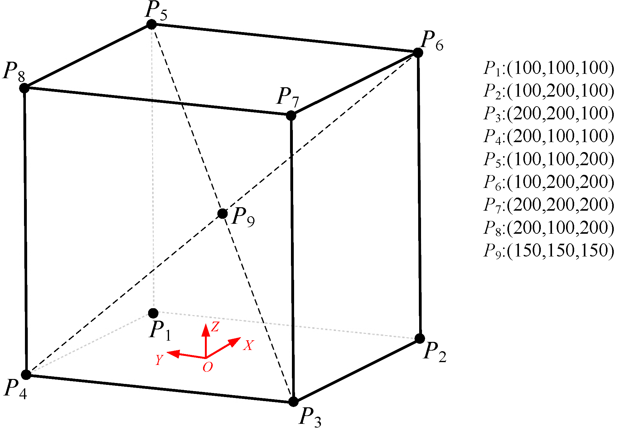
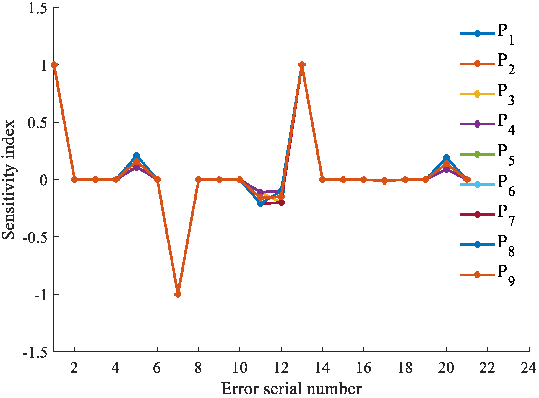
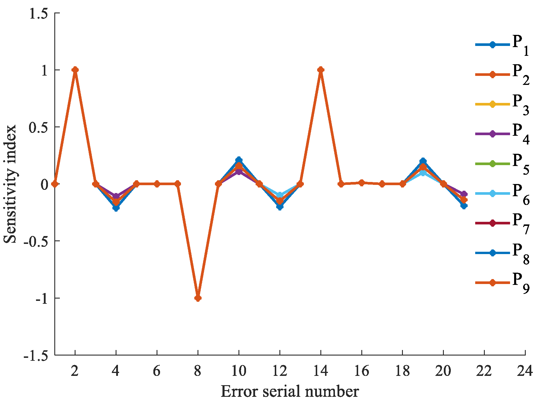
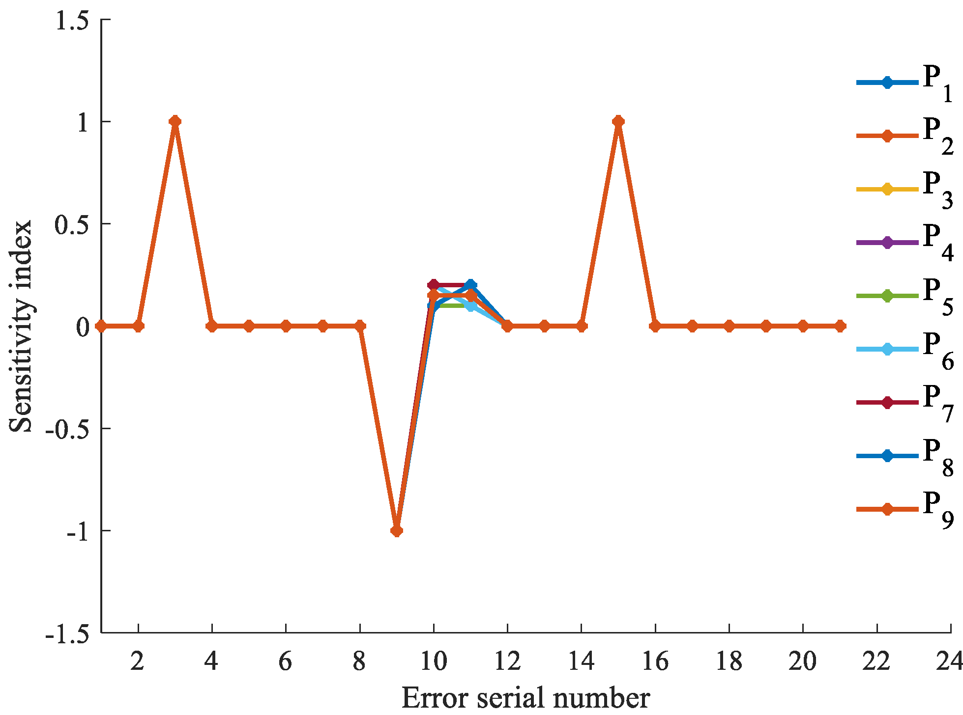
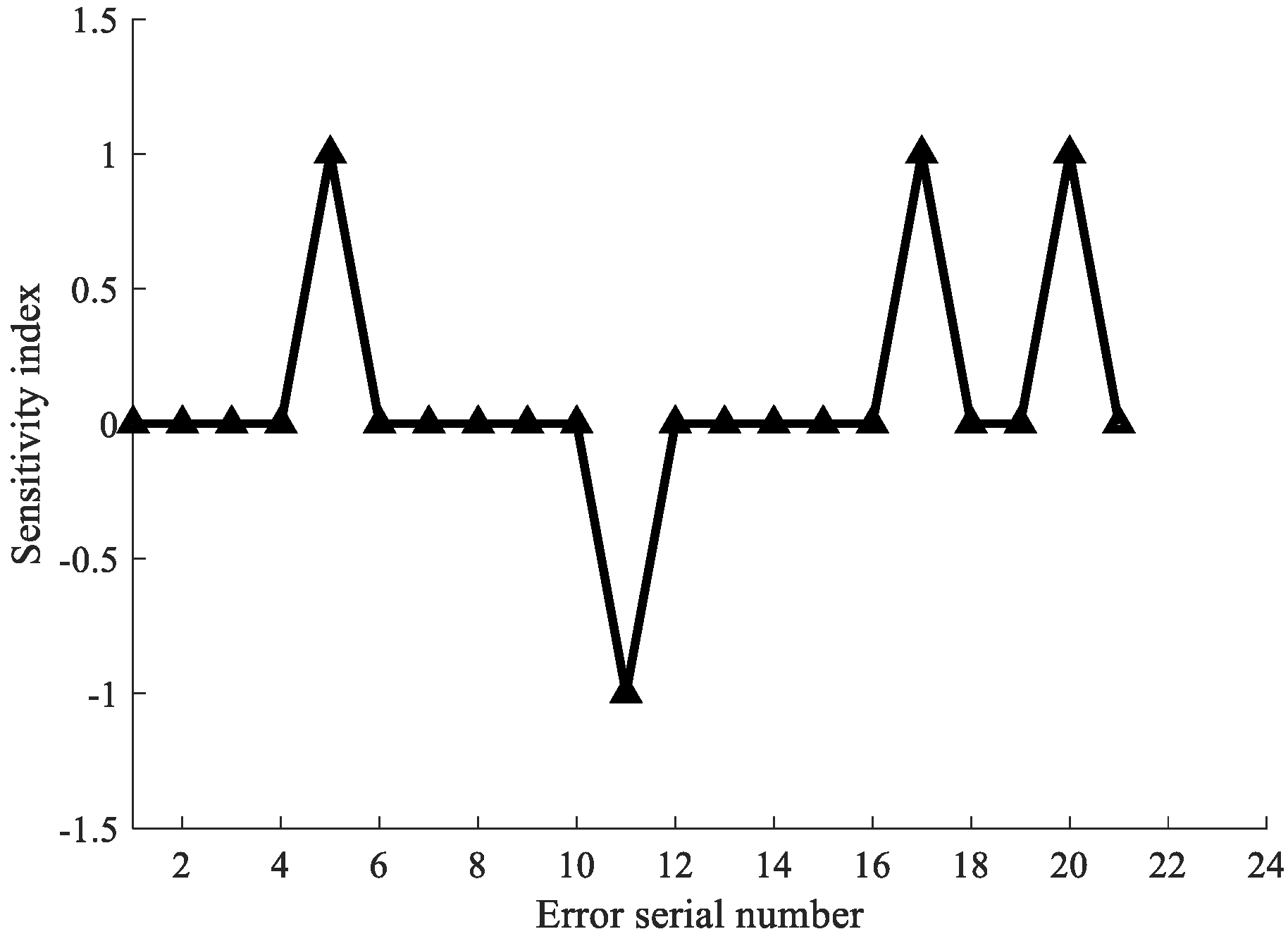
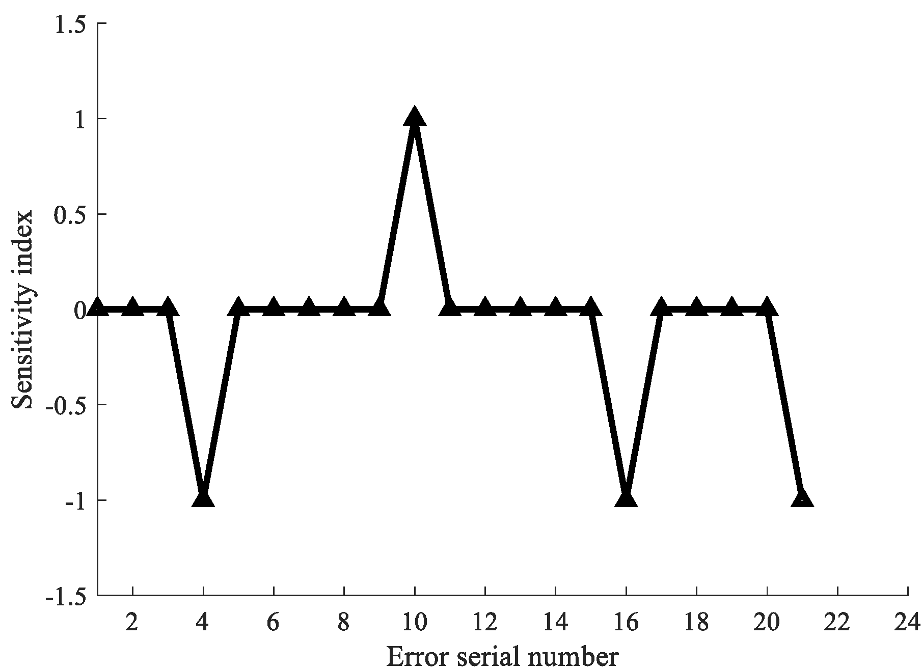
3.2. An Example to Analyze the Sensitivity of a Machine Tool
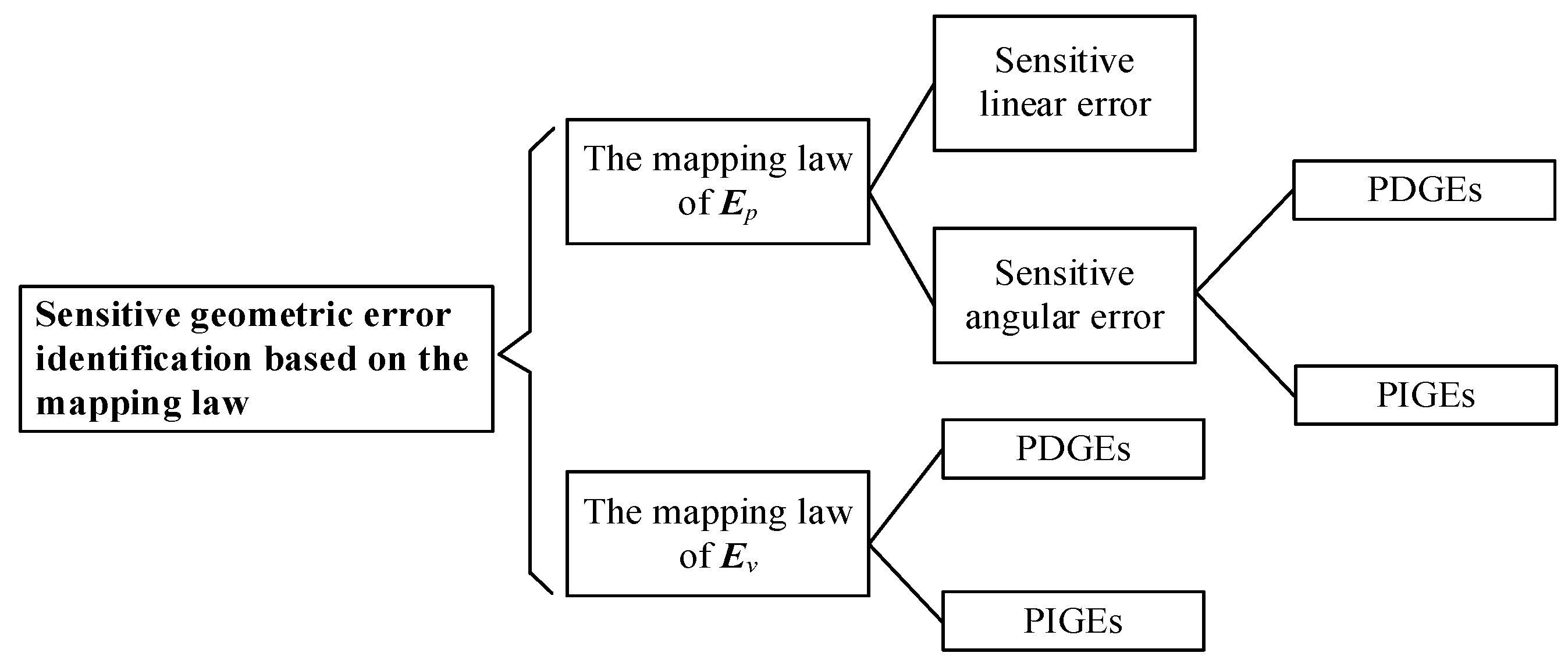
4. Mapping Law between Sensitive Geometric Errors and the Structure of a Three-Axis Remanufactured Machine Tool
4.1. Mapping Law between Sensitive Geometric Errors of Volumetric Position Error and the Structure
4.1.1. Mapping Law of Sensitive Linear Error
4.1.2. Mapping Law of Sensitive Angular Error
- (1)
- Mapping law to identify sensitive angular PDGEs
- Sensitive angular PDGEs identification of motion axis on workpiece chain.Each moving axis on workpiece chain has two sensitive angular PDGEs in the corresponding identification direction. The two errors are the angular errors around another two directions in addition to the identification direction. The sensitive angular PDGEs of the X-axis, Y-axis and Z-axis can be identified as follows:The sensitive angular PDGEs of the X-axis in the x identification direction on workpiece chain are , . The sensitive angular PDGEs of the Y-axis in the x identification direction on workpiece chain are and . The sensitive angular PDGEs of the Z-axis in the x identification direction on workpiece chain are and .The sensitive angular PDGEs of the X-axis in the y identification direction on workpiece chain are and . The sensitive angular PDGEs of the Y-axis in the y identification direction on workpiece chain are and . The sensitive angular PDGEs of the Z-axis in the y identification direction on workpiece chain are and .The sensitive angular PDGEs of the X-axis in the z identification direction on workpiece chain are and . The sensitive angular PDGEs of the Y-axis in the z identification direction on workpiece chain are and . The sensitive angular PDGEs of the Z-axis in the z identification direction on workpiece chain are and
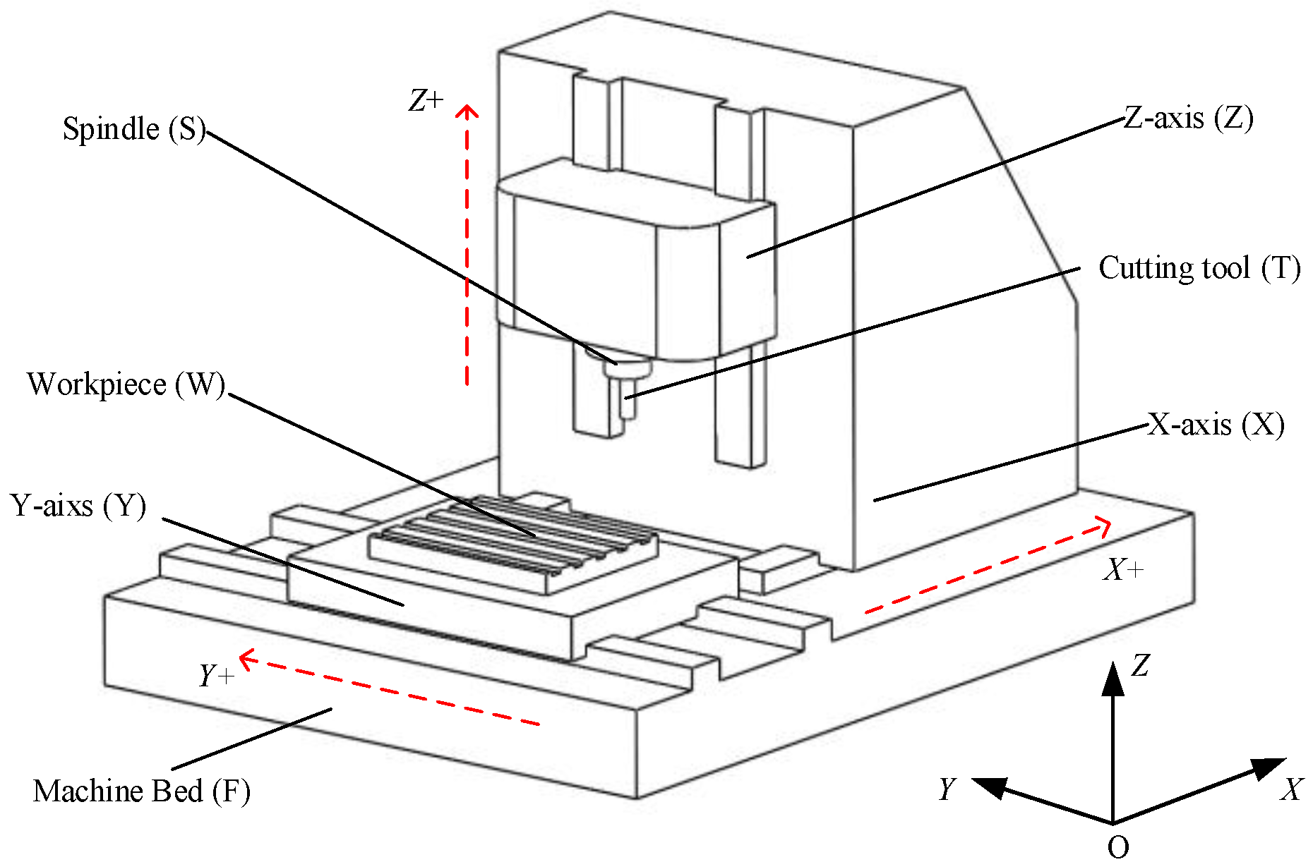
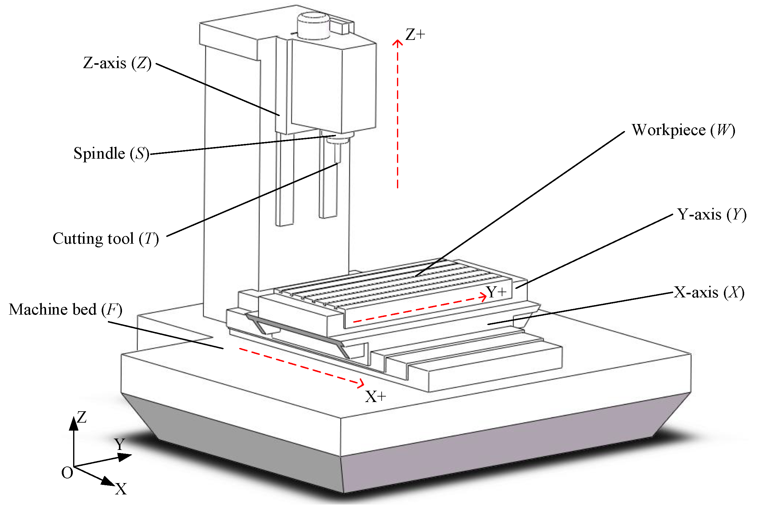
- Sensitive angular PDGEs identification of motion axis on tool chainThe relationship between the identification direction and the direction of cutter axis will affect the mapping law.If the identification direction is accordance with the direction of cutter axis. There are no sensitive angular PDGEs in the identification direction of all axes on the tool chain. As shown in Figure 1, the cutter axis is along with z direction, hence X-axis and Z-axis on the tool chain have no sensitive angular PDGEs in the identification z direction.If the identification direction is inconsistent with the cutter axis direction. Each motion axis on the tool chain has one sensitive angular PDGEs. The sensitive angular PDGEs rotated around the third axis except the identification direction and the cutter axis direction. See in Figure 1, the cutter axis is along with z direction, hence the sensitive angular PDGEs in x identification direction are and , the sensitive angular PDGEs in y identification direction are and .
- (2)
- Mapping law to identify sensitive angular PIGEs
- The identification direction consistent with the direction of motion axis next to the workpiece has two sensitive angular PIGEs. Squareness errors between the motion axis and the other two axes are the sensitive angular PIGEs. As shown in Figure 1, Y-axis is next to the workpiece, hence and are the sensitive angular PIGEs in the y direction.
- There are no sensitive angular PIGEs in the identification direction consistent with the motion axis next to the tool. As shown in Figure 1, Z-axis is next to the tool on the tool chain, hence there are no sensitive angular PIGEs in the z direction.
- The last one sensitive angular PIGE can be found in the remaining third identification direction. As shown in Figure 1, Y-axis is closest to the workpiece, and Z-axis is closest to the tool. Hence, the x identification direction corresponding to the remaining X-axis has a sensitive angular PIGE
4.2. Mapping Law between Sensitive Geometric Errors of Volumetric Posture Error and the Structure
- (1)
- Mapping law to identify sensitive angular PDGEs
- (2)
- Mapping law to identify sensitive angular PIGEs
5. Simulation and Experiments
5.1. Quick Identification of Geometric Errors Based on the Mapping Table
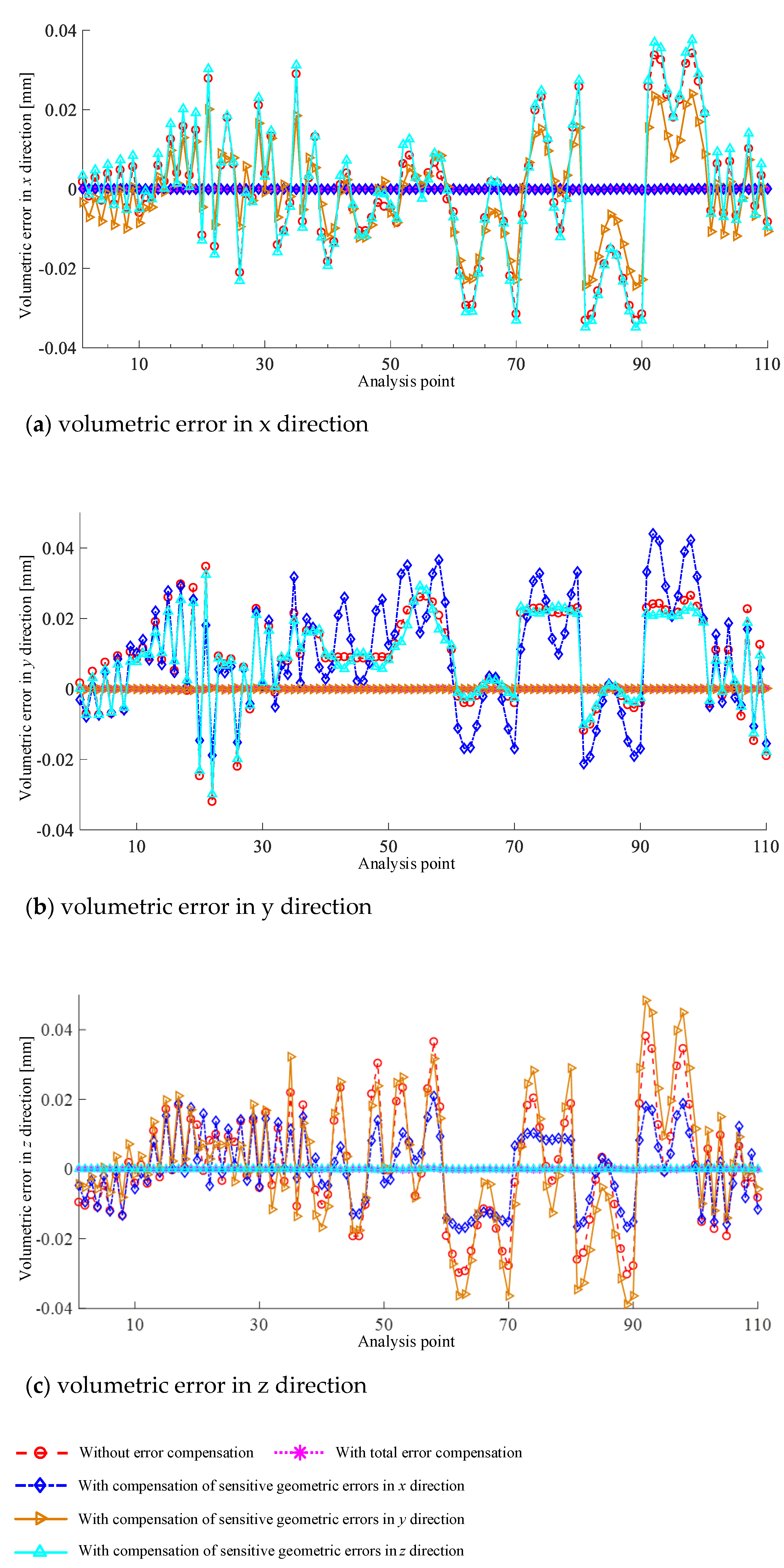
5.2. Simulation Verification
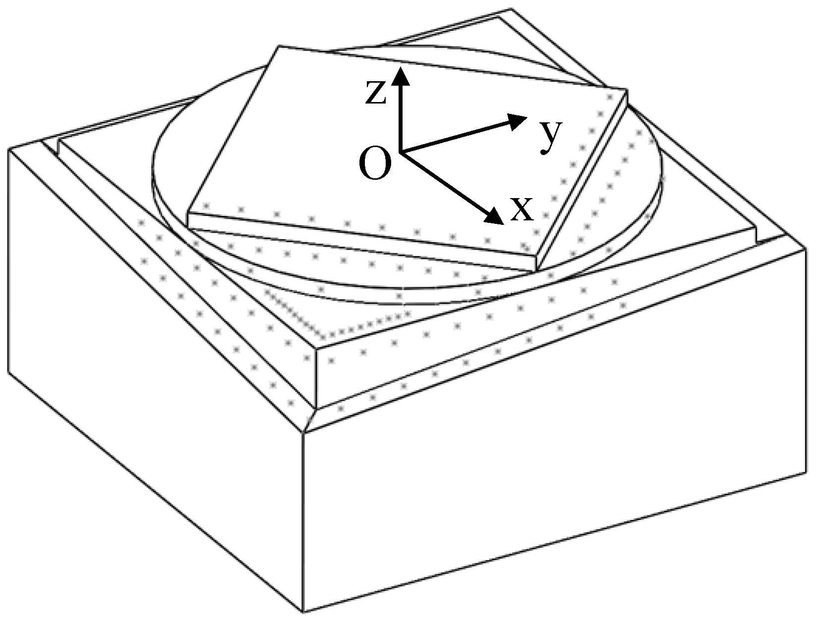
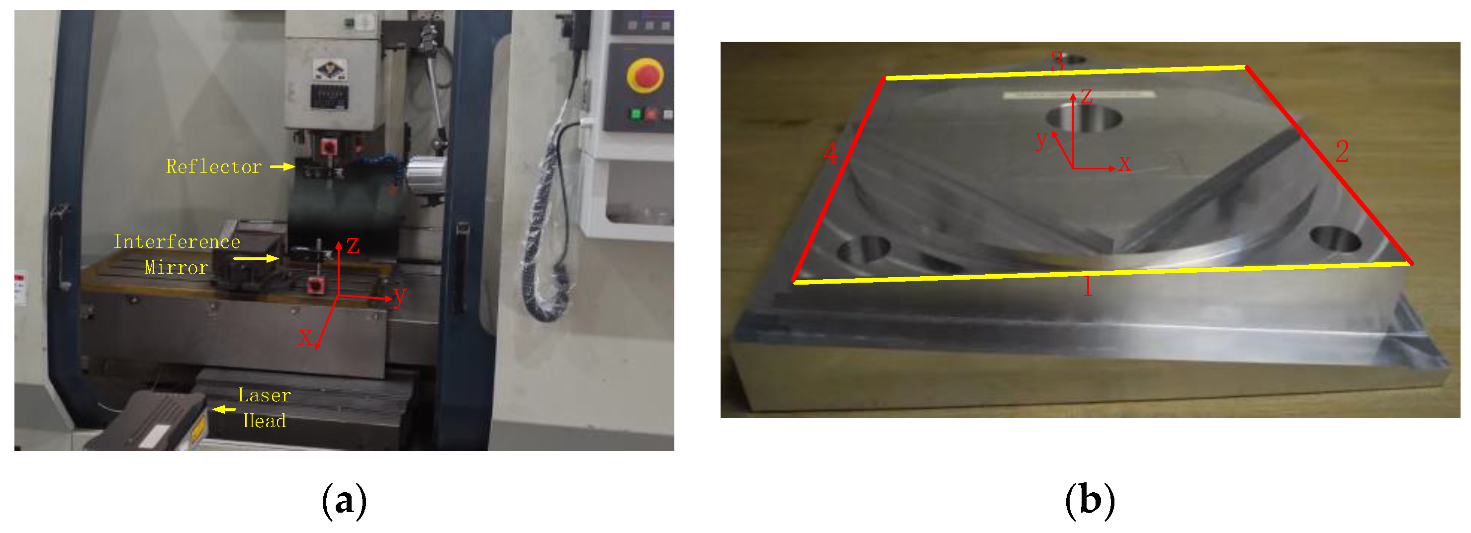
5.3. Experimental Validation
6. Conclusions
- (1)
- Based on the proposed method, sensitive geometric error terms of different three-axis machine structures can be obtained without geometric error modeling and sensitivity analysis.
- (2)
- The weak coupling relationship among the geometric errors of three-axis machine tools can be concluded, and the partial differential method was utilized to analyze the sensitivity of geometric errors.
- (3)
- Mapping tables between the sensitive geometric errors and the machine tool structure can be applied to the convenient identification of sensitive error terms without professional knowledge.
- (4)
- The identification results of sensitive geometric errors by using the proposed method are verified through simulation and experiment. The results showed that the straightness error of milling was improved up to 0.007 mm by compensating the identified sensitive geometric errors.
Author Contributions
Funding
Data Availability Statement
Conflicts of Interest
References
- Du, Y.; He, G.; Li, B.; Zhou, Z.; Wu, G. In service machine tool remanufacturing: A sustainable resource saving and high valued recovery approach. Environ. Dev. Sustain. 2022, 24, 1335–1358. [Google Scholar] [CrossRef]
- Song, Z.Q.; Ding, S.; Chen, Z.W.; Lu, Z.W.; Wang, Z.Z. High-efficient calculation method for sensitive PDGEs of five-axis reconfigurable machine tool. Machines 2021, 9, 84. [Google Scholar] [CrossRef]
- Fu, G.Q.; Fu, J.Z.; Xu, Y.T.; Chen, Z.C.; Lai, J.T. Accuracy enhancement of five-axis machine tool based on differential motion matrix: Geometric error modeling, identification and compensation. Int. J. Mach. Tools Manuf. 2015, 89, 170–181. [Google Scholar] [CrossRef]
- Yang, J.X.; Ding, H. A new position independent geometric errors identification model of five-axis serial machine tools based on differential motion matrices. Int. J. Mach. Tools Manuf. 2016, 104, 68–77. [Google Scholar] [CrossRef]
- Chen, G.H.; Zhang, L.; Wang, C.; Xiang, H.; Tong, G.Q.; Zhao, D.Z. High-precision modeling of CNCs’ spatial errors based on screw theory. SN Appl. Sci. 2022, 4, 45. [Google Scholar] [CrossRef]
- Zhong, X.M.; Liu, H.Q.; Mao, X.Y.; Li, B.; He, S.P.; Peng, F.Y. Volumetric error modeling, identification and compensation based on screw theory for a large multi-axis propeller-measuring machine. Meas. Sci. Technol. 2018, 29, 055011. [Google Scholar] [CrossRef]
- Cheng, Q.; Feng, Q.N.; Liu, Z.F.; Gu, P.H.; Cai, L.G. Fluctuation prediction of machining accuracy for multi-axis machine tool based on stochastic process theory. Proc. Inst. Mech. Eng. Part. C J. Mech. Eng. Sci. 2015, 229, 2534–2550. [Google Scholar] [CrossRef]
- Tao, H.F.; Chen, R.; Xuan, J.P.; Xia, Q.; Yang, Z.Y.; Zhang, X.; He, S.; Shi, T.L. Prioritization analysis and compensation of geometric errors for ultra-precision lathe based on the random forest methodology. Precis. Eng. 2020, 61, 23–40. [Google Scholar] [CrossRef]
- Zhou, B.C.; Wang, S.L.; Fang, C.G.; Sun, S.L.; Dai, H. Geometric error modeling and compensation for five-axis CNC gear profile grinding machine tools. Int. J. Adv. Manuf. Technol. 2017, 92, 2639–2652. [Google Scholar] [CrossRef]
- Ding, S.; Huang, X.D.; Yu, C.J.; Wang, W. Actual inverse kinematics for position-independent and position-dependent geometric error compensation of five-axis machine tools. Int. J. Mach. Tools Manuf. 2016, 111, 55–62. [Google Scholar] [CrossRef]
- Wu, H.R.; Zheng, H.L.; Wang, W.K.; Xiang, X.P.; Rong, M.L. A method for tracing key geometric errors of vertical machining center based on global sensitivity analysis. Int. J. Adv. Manuf. Technol. 2020, 106, 3943–3956. [Google Scholar] [CrossRef]
- Niu, P.; Cheng, Q.; Liu, Z.F.; Chu, H.Y. A machining accuracy improvement approach for a horizontal machining center based on analysis of geometric error characteristics. Int. J. Adv. Manuf. Technol. 2021, 112, 2873–2887. [Google Scholar] [CrossRef]
- Li, J.; Xie, F.G.; Liu, X.J. Geometric error modeling and sensitivity analysis of a five-axis machine tool. Int. J. Adv. Manuf. Technol. 2016, 82, 2037–2051. [Google Scholar] [CrossRef]
- Li, Q.Z.; Wang, W.; Jiang, Y.F.; Li, H.; Zhang, J.; Jiang, Z. A sensitivity method to analyze the volumetric error of five-axis machine tool. Int. J. Adv. Manuf. Technol. 2018, 98, 1791–1805. [Google Scholar] [CrossRef]
- Li, D.X.; Feng, P.F.; Zhang, J.F.; Yu, D.W.; Wu, Z.J. An identification method for key geometric errors of machine tool based on matrix differential and experimental test. Proc. Inst. Mech. Eng. Part. C J. Mech. Eng. Sci. 2014, 228, 3141–3155. [Google Scholar] [CrossRef]
- Cheng, Q.; Liu, G.B.; Liu, Z.F.; Xuan, D.S.; Chang, W.F. An identification approach for key geometric error sources of machine tool based on sensitivity analysis. J. Mech. Eng. 2012, 48, 171–179. (In Chinese) [Google Scholar] [CrossRef]
- Cheng, Q.; Zhao, H.W.; Zhang, G.J.; Gu, P.H.; Cai, L.G. An analytical approach for crucial geometric errors identification of multi-axis machine tool based on global sensitivity analysis. Int. J. Adv. Manuf. Technol. 2014, 75, 107–121. [Google Scholar] [CrossRef]
- Tian, W.J.; Liu, S.P.; Liu, X.X. Accuracy design of high precision machine tools using error sensitivity analysis methodology. Proc. Inst. Mech. Eng. Part. C J. Mech. Eng. Sci. 2017, 231, 3401–3413. [Google Scholar] [CrossRef]
- Liu, X.J.; Wang, Y.; Qiu, L.M.; Wu, C.R.; Zhang, P.; Zhang, S.Y. An improved geometric error analysis method considering the variety of sensitivities over working space. Adv. Mech. Eng. 2018, 10, 1–12. [Google Scholar] [CrossRef] [Green Version]
- Fan, J.W.; Tao, H.H.; Wu, C.J.; Tang, Y.H. Method of error sensitivity analysis of machine tools. J. Beijing Univ. Technol. 2019, 45, 314–321. (In Chinese) [Google Scholar]
- Fan, J.W.; Tao, H.H.; Pan, R.; Chen, D.J. An approach for accuracy enhancement of five-axis machine tools based on quantitative interval sensitivity analysis. Mech. Mach. Theory 2020, 148, 103806. [Google Scholar] [CrossRef]
- Fan, J.W.; Wang, P.T.; Ren, X.F. A novel global sensitivity analysis method for vital geometric errors of five-axis machine tools. Int. J. Adv. Manuf. Technol. 2021, 117, 3515–3527. [Google Scholar] [CrossRef]
- Guo, S.J.; Jiang, G.D.; Mei, X.S. Investigation of sensitivity analysis and compensation parameter optimization of geometric error for five-axis machine tool. Int. J. Adv. Manuf. Technol. 2017, 93, 3229–3243. [Google Scholar] [CrossRef]
- Guo, S.J.; Zhang, D.S. Geometric Error Analysis and Compensation of Rotary Axes of Five-axis Machine Tools. Adv. Eng. Sci. 2020, 52, 130–139. (In Chinese) [Google Scholar]
- Xia, C.J.; Wang, S.L.; Sun, S.L.; Lin, X.C.; Huang, X.D. Geometric error to tooth surface error model and identification of crucial errors in five-axis CNC gear profile grinding machines. Comput. Integr. Manuf. Syst. 2020, 26, 1191–1201. (In Chinese) [Google Scholar]
- Li, P.Z.; Zhao, R.H.; Luo, L. A geometric accuracy error analysis method for turn-milling combined NC machine tool. Symmetry 2020, 12, 1622. [Google Scholar] [CrossRef]
- Zou, X.C.; Zhao, X.S.; Wang, Z.W.; Li, G.; Hu, Z.J.; Sun, T. Error distribution of a 5-Axis measuring machine based on sensitivity analysis of geometric errors. Math. Probl. Eng. 2020, 2020, 8146975. [Google Scholar] [CrossRef]
- Tang, H.; Duan, J.A.; Lan, S.H.; Shui, H.Y. A new geometric error modeling approach for multi-axis system based on stream of variation theory. Int. J. Mach. Tools Manuf. 2015, 92, 41–51. [Google Scholar] [CrossRef]
- Fu, G.Q.; Rao, Y.J.; Xie, Y.P.; Gao, H.L.; Deng, X.L. Error sensitivity analysis of motion axis for five-axis CNC machine tools with geometric error contribution. China Mech. Eng. 2020, 31, 1518–1528. (In Chinese) [Google Scholar]
- Jiang, X.G.; Cui, Z.W.; Wang, L.; Liu, C.; Li, M.J.; Liu, J.; Du, Y. Critical geometric errors identification of a five-axis machine tool based on global quantitative sensitivity analysis. Int. J. Adv. Manuf. Technol. 2022, 119, 3717–3727. [Google Scholar] [CrossRef]
- Dai, K.; Zhang, S.; Shu, Y.; Zhang, W.; Zhang, Z. Modified identification method of geometric error for translational axis of CNC machine tools. Comput. Integr. Manuf. Syst. 2021, 27, 1319–1327. (In Chinese) [Google Scholar]
| Movement Axis | Physical Meaning of Each Error Term | Symbols | Error Serial Number |
|---|---|---|---|
| X | Positioning error of the X-axis in the x direction | 1 | |
| Straightness error of X-axis in y direction | 2 | ||
| Straightness error of X-axis in z direction | 3 | ||
| Rolling error of X-axis around x direction | 4 | ||
| Angular error of X-axis around y direction | 5 | ||
| Angular error of X-axis around z direction | 6 | ||
| Y | Straightness error of Y-axis in x direction | 7 | |
| Positioning error of Y-axis in y direction | 8 | ||
| Straightness error of Y-axis in z direction | 9 | ||
| Angular error of Y-axis around x direction | 10 | ||
| Rolling error of Y-axis around y direction | 11 | ||
| Angular error of Y-axis around z direction | 12 | ||
| Z | Straightness error of Z-axis in x direction | 13 | |
| Straightness error of Z-axis in y direction | 14 | ||
| Positioning error of Z-axis in z direction | 15 | ||
| Angular error of Z-axis around x direction | 16 | ||
| Angular error of Z-axis around y direction | 17 | ||
| Rolling error of Z-axis around z direction | 18 | ||
| Assembly errors | Perpendicularity error between X-axis and Y-axis | 19 | |
| Perpendicularity error between X-axis and Z-axis | 20 | ||
| Perpendicularity error between Y-axis and Z-axis | 21 |
| Identification Direction | Sensitive Geometric Errors of Volumetric Position Error | |||||||||||||
|---|---|---|---|---|---|---|---|---|---|---|---|---|---|---|
| Sensitive Linear Error | Sensitive Angular Errors | |||||||||||||
| PDGEs | PIGEs | |||||||||||||
| Workpiece Chain | Tool Chain | Motion Axis Next to the Workpiece | Motion Axis Next to the Tool | The Third Motion Axis | ||||||||||
| If There Is No Motion Axis on the Corresponding Chain, the Corresponding PDGEs Are Removed | ||||||||||||||
| X | Y | Z | Direction of Cutter Axis | X | Y | Z | X | Y | Z | |||||
| x | y | z | ||||||||||||
| x | -- | -- | The sensitive angular PIGEs in the third direction of motion axis is the squareness error that not appeared in the direction of motion axis next to the workpiece. For example: if X-axis is next to the workpiece, the sensitive angular PIGEs in the third direction is . | |||||||||||
| y | -- | -- | ||||||||||||
| z | -- | -- | ||||||||||||
| Identification Direction | Sensitive Geometric Errors of Volumetric Posture Error | |||||
|---|---|---|---|---|---|---|
| PDGEs | PIGEs | |||||
| Direction of Cutter Axis | Direction of Cutter Axis | |||||
| x | y | z | x | y | z | |
| x | -- | -- | ||||
| y | -- | -- | ||||
| z | -- | -- | ||||
| Identification Direction | Sensitive Geometric Errors of Volumetric Position Error | ||||||
|---|---|---|---|---|---|---|---|
| Sensitive Linear Error | Sensitive Angular Errors | ||||||
| PDGEs | PIGEs | ||||||
| Workpiece Chain | Tool Chain | Motion Axis Next to the Workpiece | Motion Axis Next to the Tool | The Third Motion Axis | |||
| If There Is No Motion Axis on the Corresponding Chain, the Corresponding PDGEs Are Removed | |||||||
| X | Y | Direction of Cutter Axis | Y | Z | |||
| z | |||||||
| x | |||||||
| y | |||||||
| z | -- | -- | |||||
| Identification Direction | Sensitive Geometric Errors of Volumetric Posture Error | |
|---|---|---|
| PDGEs | PIGEs | |
| Direction of Cutter Axis | Direction of Cutter Axis | |
| z | z | |
| x | ||
| y | ||
| z | -- | -- |
| X/Y/Z Position (mm) | 0 | 11 | 22 | 33 | 44 | 55 | 66 | 77 | 88 | 99 | 110 |
|---|---|---|---|---|---|---|---|---|---|---|---|
| (µm) | −0.5 | 1 | 2.5 | 3.5 | 5 | 6 | 8 | 9 | 11 | 13 | 15 |
| (µm) | 2 | 2.5 | 2.5 | 0.5 | −1.5 | −2 | −2 | −1 | 1 | 3 | 3 |
| (µm) | 3 | 3 | 0 | −1 | −1 | −2 | −1 | −0.5 | 0 | 1 | 1 |
| (s) | −0.5 | 1 | 2 | 2.5 | 3 | 4 | 4 | 5 | 6 | 6.5 | 7 |
| (s) | 0.5 | 1.5 | 2.5 | 4 | 5 | 6.5 | 6 | 7 | 7.5 | 6 | 5.5 |
| (s) | 0.5 | 1 | 2 | 3.5 | 4.5 | 6 | 6.5 | 6 | 6 | 6.5 | 6.5 |
| (µm) | 0 | 0.5 | 1 | 0.5 | 0 | 0.5 | 0.5 | 0 | 1 | 0.5 | 0 |
| (µm) | −3.5 | −7 | −7 | −7 | −9 | −7 | −5 | −1 | 3 | 5 | 5 |
| (µm) | −0.5 | 0 | 1 | 5 | 1 | 0 | −0.5 | 0 | 0.5 | 1 | 3 |
| (s) | −0.5 | 0 | 1 | 2 | 3 | 3.5 | 4.5 | 5 | 6 | 6 | 6 |
| (s) | 1.5 | 3.5 | 5.5 | 6.5 | 8 | 9 | 9 | 9 | 7.5 | 7.5 | 7.5 |
| (s) | 0 | 1 | 3 | 4 | 5 | 6 | 8 | 9 | 9 | 10 | 11 |
| (µm) | −3 | −1 | 1 | 2 | 1 | 0 | 1 | 1 | 0 | −1 | −2 |
| (µm) | 2 | −10 | 2 | 4 | 3 | 2 | 2 | 0 | 0 | −1 | −3 |
| (µm) | −4 | −2.5 | 6 | −0.5 | 2 | −1.5 | −0.5 | −3.5 | 1.5 | 2.5 | −3.5 |
| (s) | 0.5 | 1.5 | 1.5 | 3 | 4 | 3 | 4 | 3 | 4 | 4 | 5 |
| (s) | −1.5 | −2 | 2.5 | −2.5 | −2.5 | −1.5 | −1.5 | −1.5 | −0.5 | 0.5 | 1 |
| (s) | 0 | 0 | 0 | 0 | 0 | 0 | 0 | 0 | 0 | 0 | 0 |
| (s) | 5 | ||||||||||
| (s) | −22.5 | ||||||||||
| (s) | 45.5 | ||||||||||
Publisher’s Note: MDPI stays neutral with regard to jurisdictional claims in published maps and institutional affiliations. |
© 2022 by the authors. Licensee MDPI, Basel, Switzerland. This article is an open access article distributed under the terms and conditions of the Creative Commons Attribution (CC BY) license (https://creativecommons.org/licenses/by/4.0/).
Share and Cite
Ding, W.; Song, Z.; Ding, S. Investigation on Structural Mapping Laws of Sensitive Geometric Errors Oriented to Remanufacturing of Three-Axis Milling Machine Tools. Machines 2022, 10, 341. https://doi.org/10.3390/machines10050341
Ding W, Song Z, Ding S. Investigation on Structural Mapping Laws of Sensitive Geometric Errors Oriented to Remanufacturing of Three-Axis Milling Machine Tools. Machines. 2022; 10(5):341. https://doi.org/10.3390/machines10050341
Chicago/Turabian StyleDing, Wenzheng, Zhanqun Song, and Shuang Ding. 2022. "Investigation on Structural Mapping Laws of Sensitive Geometric Errors Oriented to Remanufacturing of Three-Axis Milling Machine Tools" Machines 10, no. 5: 341. https://doi.org/10.3390/machines10050341
APA StyleDing, W., Song, Z., & Ding, S. (2022). Investigation on Structural Mapping Laws of Sensitive Geometric Errors Oriented to Remanufacturing of Three-Axis Milling Machine Tools. Machines, 10(5), 341. https://doi.org/10.3390/machines10050341


