Article

Practical Obstacle-Overcoming Robot with a Heterogeneous Sensing System: Design and Experiments

1
School of Aviation, Inner Mongolia University of Technology, Hohhot 010021, China
2
School of Vehicle and Mobility, Tsinghua University, Beijing 100190, China
3
School of Electronics and Control Engineering, Institute of Disaster Prevention, Sanhe 065201, China
*
Author to whom correspondence should be addressed.
These authors contributed equally to this work.
Machines 2022, 10(5), 289; https://doi.org/10.3390/machines10050289
Submission received: 25 March 2022 / Revised: 12 April 2022 / Accepted: 19 April 2022 / Published: 21 April 2022
(This article belongs to the Special Issue Heterogeneity in Intelligent Mobile Robots and Systems)

Abstract

:
It is challenging for robots to improve their ability to pass through unstructured environments while maximizing motion performance in cities and factories. This paper presents an omnidirectional deformable wheeled robot based on a heterogeneous sensing system. We presented a novel structure with dual swing arms and six wheels. Moreover, the heterogeneous sensing system can perceive critical environmental data, such as friction and temperature, to assist the robot in executing different functions. In addition, a top-down ‘Order–Decision–Behaviour’ overall motion strategy is proposed based on the data acquisition. The strategy combines the key condition parameters with a kinetic model to integrate the robot’s movement, overcoming of obstacles, and mode switching. The robot is flexible and fast in moving mode and can overcome obstacles safely, reliably, and simply. This study describes the robot’s design, strategy, simulation, and experiments. Motion performance and strategy were investigated and evaluated in field environments.

Graphical Abstract

1. Introduction

In unstructured scenarios such as towns and factories, where flat surfaces predominate, mobile robots can effectively reduce or replace human labour and ensure personal safety [1]. Various robots have been gradually introduced in transportation, inspection, rescue, reconnaissance, planetary exploration, petrochemical applications, industrial automation, and interventions in extreme environments. However, when performing tasks in complex situations, making robots both passable and flexible remains a significant challenge. On the one hand, the design of the robot determines whether it is practical and reliable. On the other hand, targeted perception systems can provide references for robots to perform complex actions. Researchers have presented two main methods for improving the ability of robots to overcome obstacles. One approach is to design unique structures to make robots suitable for unstructured obstacles. Another approach is to focus on the patterns of the robots’ behaviour by altering their movements to suit the task scenarios. Meanwhile, they tend to add sensing equipment to the robot to improve its autonomy ability.
The robot’s design differed significantly from the two design concepts mentioned above. There are two distinct broad categories of robots: bionic and wheeled robots. Scientists have been inspired by creatures such as snakes [2,3], spiders [4], and dogs [5,6,7,8,9] in the design of bionic mobile robots. Bionic robots can perform well in specific scenarios owing to their unique structural designs and behavioural patterns. However, complex dynamic models have a higher demand for control and perception. Wheeled robots exhibit strong movement performance on flat roads [1]. Even though suspension enables robots to cross uneven surfaces successfully, they still cannot overcome steep obstacles. Researchers attempted to design various structures to address this issue. Robots can overcome steep but low barriers by increasing the wheel diameter and changing the wheel structure. Furthermore, to adapt to the loose and uneven terrain of the planetary surface, scientists designed a robot as a six-wheeled structure with dual front-side swing arms [10,11,12]. The design improves the stability of the chassis and the ability to cross the loose surface through the extra support wheels and contact area to the ground [13,14]. Based on this, scholars designed actively deformable structures to improve their ability to overcome higher and steeper obstacles [15].
The development of wheeled robots maintains a balance between plane movement speed and the ability to overcome obstacles [16,17,18]. These robots steer using differential drive wheels, which are reliable and fast. However, it is difficult to cross narrow areas due to the large turning radius. Wheels with the ability to move omnidirectionally are gradually replacing ordinary wheels. The most common one is the Mecanum wheel, which helps robots achieve omnidirectional mobility tasks through a rich combination of spaces. Nevertheless, owing to the high layout requirements of omnidirectional wheels, they are rarely used in the design of robots with the ability to overcome obstacles [19].
Meanwhile, mobile robots use perceptual devices widely, and heterogeneous sensing systems are studied to increase robots’ autonomy in various environments. Robots must rely on accurate sensor models to process the collected information and often fuse information from multiple sensors to improve performance. Simultaneous localization and mapping attract great attention nowadays. Scholars use one or more sensors such as stereo cameras, lidars, radars and millimetre-wave radars for environmental perception and building a model of the environment. However, heterogeneous perception systems for particular tasks are not complete. For most obstacle surmounting robots, obstacle height and friction coefficient are the critical parameters of the obstacle overcoming process.
Considering the characteristics of wheeled robots and the Mecanum wheel, this study proposes a novel robot, as shown in Figure 1. The dual swing arms and six-wheel structure are innovative, and the robot can move in all directions. Otherwise, it combines the ability to overcome obstacles with the agility of omnidirectional robots. In addition, we propose a heterogeneous sensing system that combines the working principle and dynamic model of the obstacle-overcoming robot. The main advantages of this study are as follows:
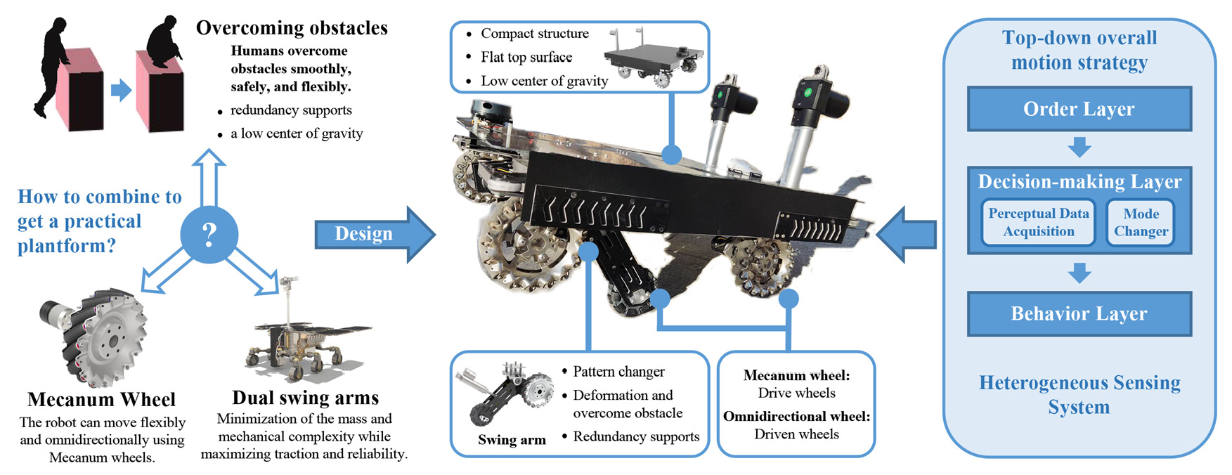
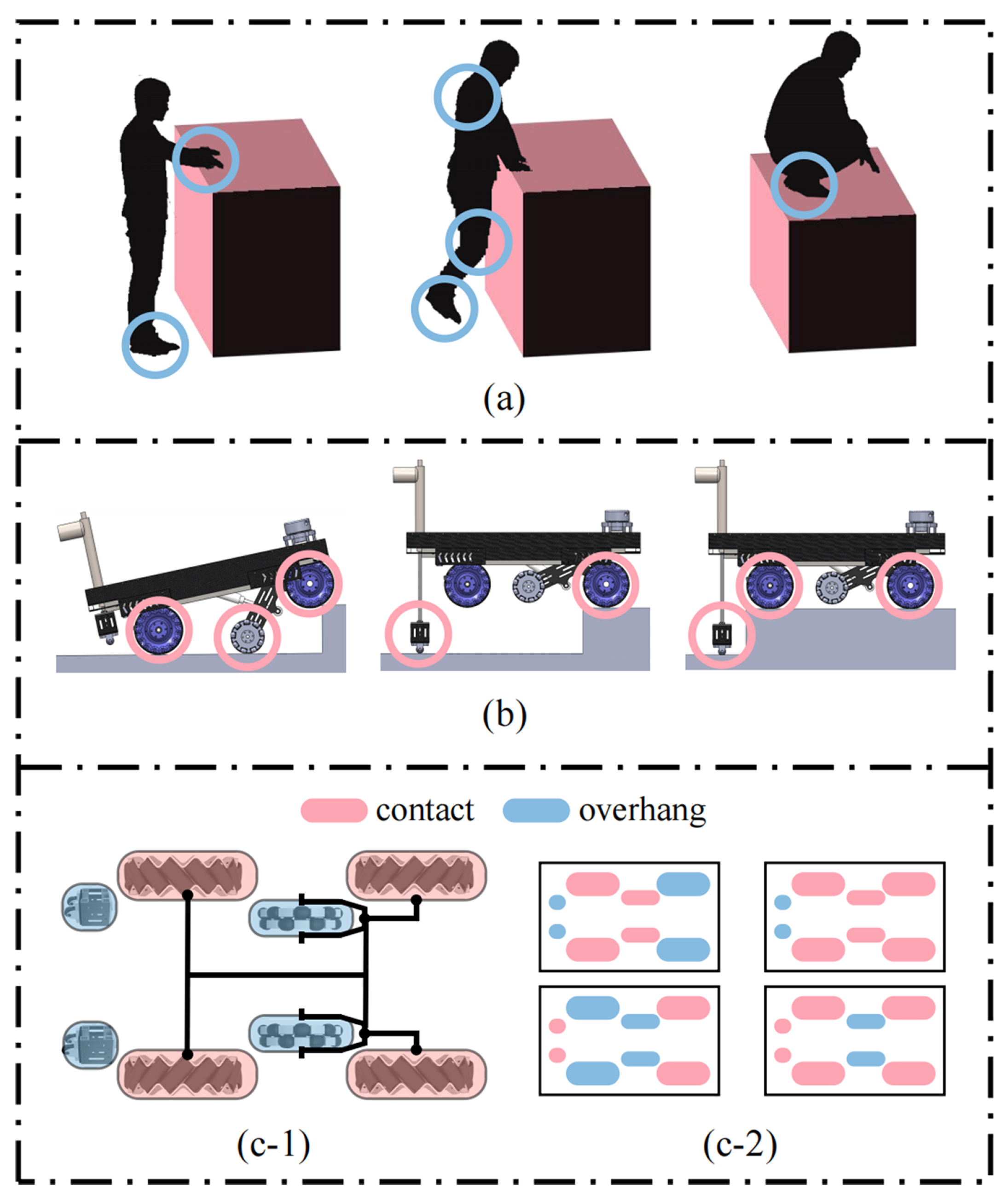
  • The robot has a compact construct, a flat upper surface and high load capacity, and it is reliable in different motion modes. It can work for different application scenarios and easily facilitate actuators or load payloads, such as robotic arms.
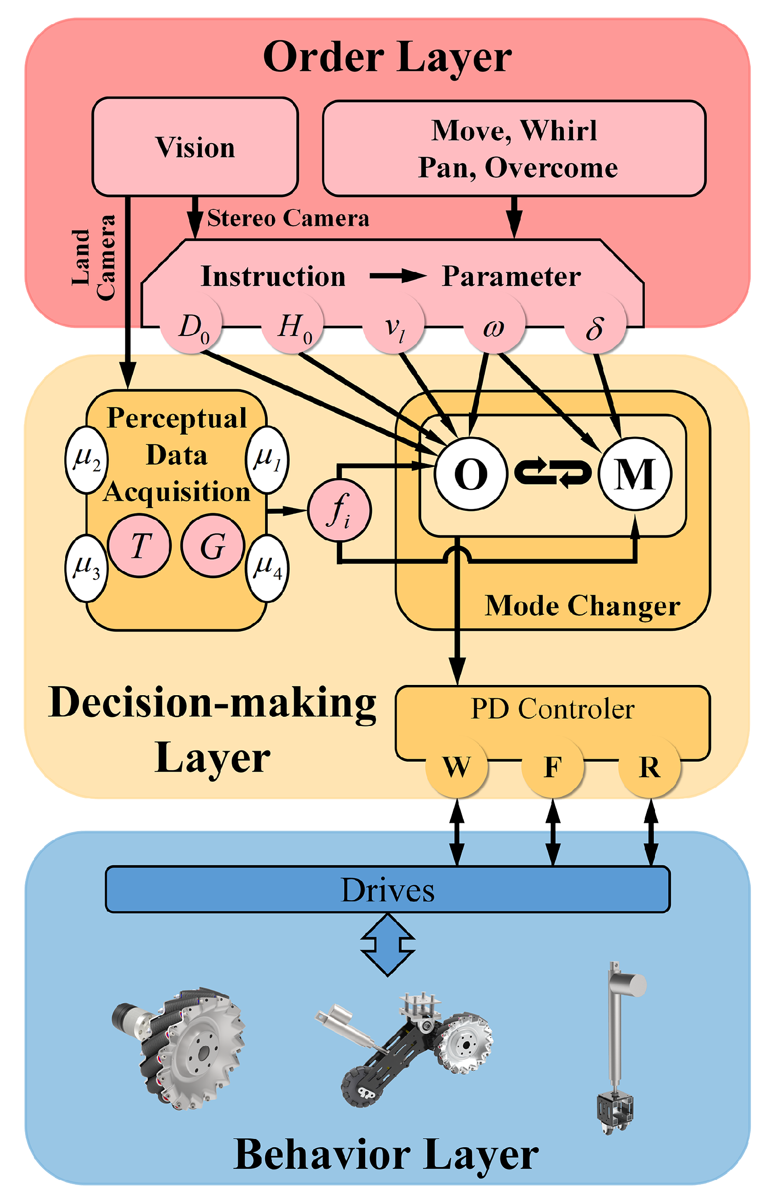
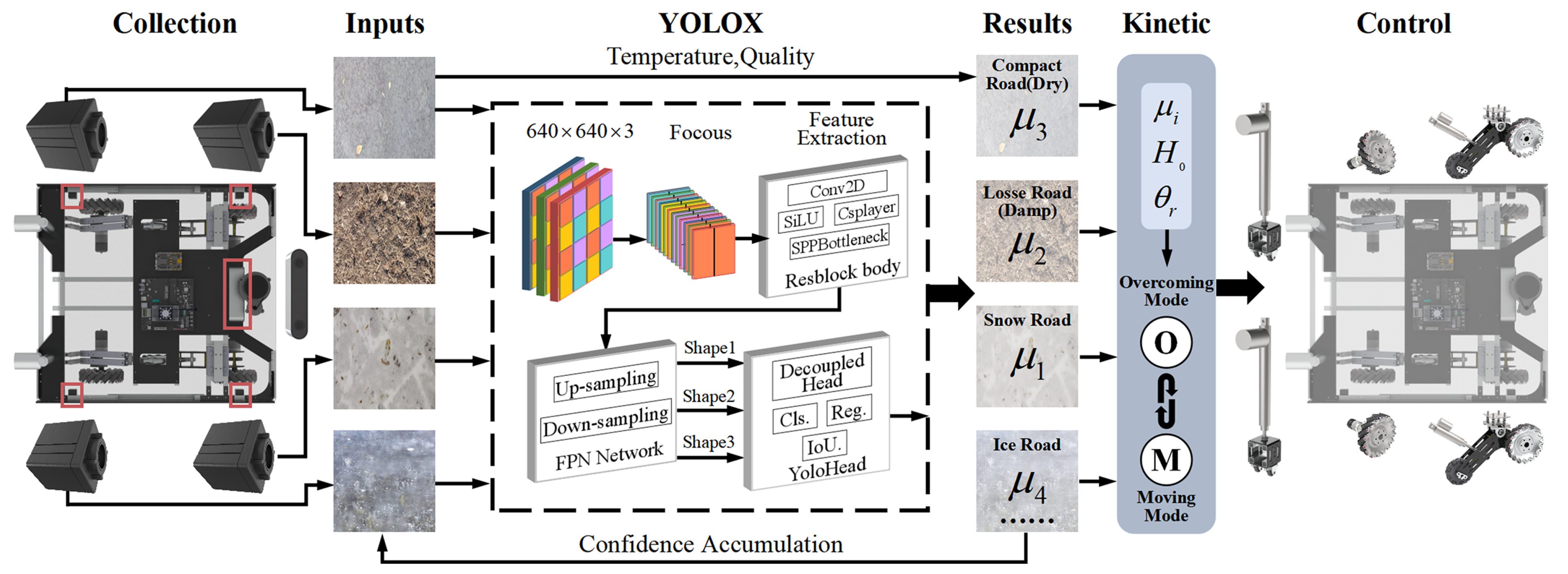
  • A heterogeneous perception system is designed to solve the complex problem of robot motion execution in various scenes.
  • An overall motion strategy is presented for the robot. The strategy is based on heterogeneous sensing systems and the determination of motion parameters for overcoming obstacles. The robot performs stably using this strategy when overcoming obstacles in complex environments.
There have been some attempts to design variable structure omnidirectional overcoming robots with redundancy supports, but few studies have considered the effect of friction on the obstacle overcoming process [13,20]. This study combines four Mecanum wheels and two driven omnidirectional wheels. The robot can switch modes between motion mode and overcoming mode. In the motion mode, the robot has only four Mecanum wheels in contact with the ground, similar to a typical Mecanum wheel-based mobile robot. At this point, the robot’s omnidirectional wheels are retracted to the inside. When the robot switches to the overcoming mode, it can rely on a deformable structure and redundancy support to overcome obstacles. The multi-modal motion behaviour and perception systems of robots are also the focus of research. This study presents a detailed robot modelling and heterogeneous sensing system considering friction coefficients. The overall motion strategy based on sensing data acquisition ensures that overcoming obstacles is stable and reliable.
The remainder of this paper is as follows: Section 2 reviews the latest research work on obstacle-overcoming robots, and Section 3 presents the design of the robot platform, focusing on the robot design concept, prototype platform and numerical modelling. Section 4 presents the robot’s approach to moving and overcoming obstacles, including the heterogeneous sensing system, data acquisition, and overall motion strategy. Section 5 reports on the experimental setup and results of the robot, and the results are analysed and discussed. Section 6 summarizes this work and presents an outlook for future work.

2. Related Works

One would expect the robot to overcome obstacles because the task environment can be complex. Re-routing the travel path is an effective solution when the robot encounters an obstacle that can be avoided: efficient obstacle avoidance and path planning place high demands on the sensory systems of robots. Bypassing barriers is simple and effective [21]. The SRM Institute of Science and Technology designed a robot based on displacement collaboration strategies [22]. It can pass through small obstacles or narrow areas without changing the direction of travel. The advantage of this approach is that when the robot has effective environmental awareness and decision-making capabilities; it can save time by bypassing obstacles. However, many obstacles in complex task environments cannot be bypassed or ignored, and most previous studies have neglected to discuss this issue.
Robots that can overcome obstacles are currently in the mainstream research direction. Hanyang University presented a typical small robot with angled-spoke-based wheels [23]. The robot can overcome obstacles lower than a height of 0.7 times the spoke length. A structure with dual swing arms and six wheels is widely used in planetary surface exploration [14]. The motion subsystem of a robot is usually based on minimizing mass and mechanical complexity while maximizing traction and reliability. Curiosity [11] and lunar rover Yutu [10,12] are the most advanced designs to date. Planetary robots have made breakthroughs in energy consumption and autonomy, but their ability to overcome steep obstacles is limited. They can only overcome obstacles that are not larger than the size of their wheels. The designs of the Swiss Federal Institute of Technology Lausanne and the Auckland University of Technology solved this problem [15]. The robot could overcome unstructured obstacles of up to two times its wheel diameter. The presented concept has significant manoeuvrability advantages in high-frictional terrains [13]. The frictional characteristics of the ground have a strong influence on the ability to overcome barriers of the robots [15]. These studies indicate that robots can overcome obstacles using their unique structures without extra power. Nevertheless, it is difficult for the robots to overcome higher obstacles and obstacles with low-friction surfaces.
Without considering the extreme energy savings, deformation and overcoming obstacles can effectively reduce the effect of the friction coefficient on robots. Bionic robots [4,24], especially legged robots [4], have a significant advantage in unstructured scenarios owing to their particular behavioural system. Many robots have been actively researched and developed, such as the MIT Cheetah Robot [7,8] and the Legged Squad Support System (LS3) quadruped vehicle [9]. Quadruped robots can be used to negotiate a range of mild terrain irregularities by quasi-static traversal. However, the most challenging obstacles require robots to skillfully plan and execute dynamic behaviours. With this question, researchers presented new algorithms to enable robots to overcome obstacles smoothly [5,7]. Nevertheless, the energy efficiencies, working speed, and agility of legged robots are still significantly worse than those of wheeled robots with similar capabilities [14]. Together, these studies provide important insights into suitable solutions for unstructured scenarios.
Researchers also presented wheeled robots with special designs, such as deformable wheels [25,26,27] and deformable bodies [28,29,30]. The Mobility Enhancement roBotic (MEBot) wheelchair was fitted with a pneumatic actuator on a frame with six wheels [18]. The robot overcomes obstacles using redundancy support points and deformable structures. Similar to the robot above, Jiangnan University studied a wheelchair with a variable structure to overcome the obstacles [17]. These robots benefit from a stable structure and actuators to achieve payload capacity. Heavy and large structures also influence the agility of the robot. Politecnico di Torino presented an innovative solution for a small hybrid mobile robot [31]. Its operating mode adapts to the ground conditions and changes accordingly, and it is easy to control with only a few actuators. Nevertheless, the differential steering mechanism increases the turning radius of the robot. The mechanism makes it difficult for the robots to navigate and turn in tight spaces. We addressed this issue using a unique selection and design. Some academics have combined variable-structure robots with Mecanum wheels. This is an excellent attempt to overcome the incomplete constraints of conventional wheels. The proper functioning of the several types of omnidirectional wheels fixes the requirements for their support structure and topology distribution [19]. Such features significantly limit the design possibilities for robots. The Korea University of Technology and Education presents wheel-leg mechanisms with agile omnidirectional mobile ability [17]. The robot is suitable for the human environment because of its stability, efficiency, and simple mechanisms. Mecanum wheels linked with variable legs allowed the robot to overcome obstacles and cross narrow channels. When overcoming obstacles, the passive wheels maintain the body balanced by redundancy support points. However, the focus of the above studies is still somewhat narrow and mainly concerned with achieving functionality.
Otherwise, robots use various heterogeneous sensors to achieve complete sensing tasks. Such as lidar and radar are commonly used in positioning and mapping tasks. There are also stereo cameras commonly used in object detection and measurement tasks [32]. There is no doubt that a heterogeneous sensing system is also a critical component of multi-robot collaboration and multi-modal independent robots. Tarbiat Modares University used multiple robots equipped with heterogeneous sensing devices to map the location environment jointly [33]. The Korea University of Technology and Education designed and optimized the obstacle-overcoming process with variable structure. They used inertial measurement unit (IMU) sensors and torque feedback information to improve the smoothness of the robot’s multi-modal motion execution [34]. Human pose estimation and tracking in real-time from multi-sensor systems are essential for many applications. The perception system is challenging to modularize due to the different structure and motion principles of robots with multi-modality [35]. Scholars often design heterogeneous perception systems according to their needs.
Two important themes emerged from the studies above discussed so far. First, the design of the robot should be compact and practical. The other is how to overcome obstacles safely, reliably, and simply. The first theme was inspired by the planetary robots and the principle of overcoming obstacles in humans. The planetary robot’s agile suspension and dual swing arm structure adapt to complex environments. Humans overcome obstacles with the help of arms, elbows, and knees, which are redundant when they walk. Considering this, we propose an innovative robot with dual swing arms and six wheels. For the second problem, an overall motion strategy is presented. We designed a heterogeneous sensing system that considers the ground friction coefficient. The overall motion strategy of the robot was also designed based on a top-down strategy using abstract commands.

3. Design of Robotic Platform

3.1. Design Concept

Humans can walk and run with just their feet. Figure 2a shows that several parts of the body are used to provide support and keep balance when humans overcome obstacles, such as the feet, hands, and knees [36]. The requirements of topology limit the design of the robot with Mecanum wheels. Extend this to a larger scale, and it is hard to combine Mecanum with existing robots [19]. The principle of robots’ design cannot make Mecanum wheels work well during the overcoming process. Meanwhile, it is necessary to consider the size and application of the robot. In addition, lowering or adjusting the centre of gravity is the primary strategy for humans to keep balance. Thus, a robot based on Mecanum wheels adopting a similar strategy as humans is appropriate.
The robot should move with only Mecanum wheels and gain enough support points in other gestures. The structure of planetary robots does well at overcoming unstructured terrain because of their dual swing arms. The robot was designed with a particular structure to the shrink swing arms inside the body to maintain agile mobility. Figure 2b illustrates the scheme of the robot in this paper based on the above concept. The robot lifts its front wheels to climb the obstacles and relies on rear putters to lift the rare part. There are multiple support points at each stage of overcoming obstacles to keep the robot stable. The area of support points should be as comprehensive as possible. Figure 2c demonstrate all supports situations clearly. The support points in the motion mode are shown in Figure 2(c-1). The low centre of gravity and the wide chassis make the robot stable. Otherwise, we made sacrifices to enable the robot to be used in a broader range of applications. The robot does not have a lot of fancy skills. The simple way of crossing obstacles and the compact structure make it more reliable and safe in its application. Figure 2(c-2) shows the other supporting situations. Although one case seems unstable, we have verified and illustrated it in Section 5 with tests.

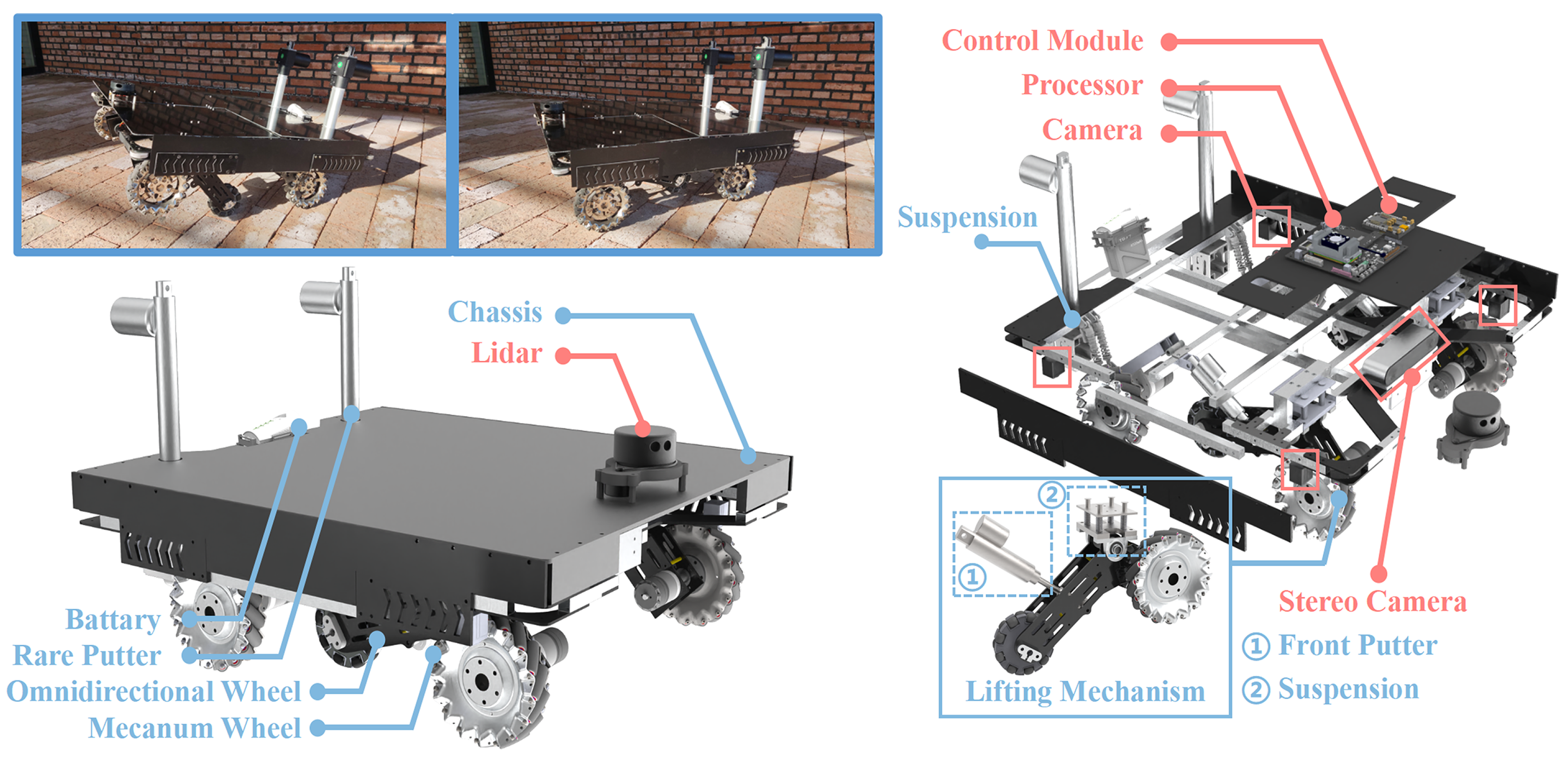
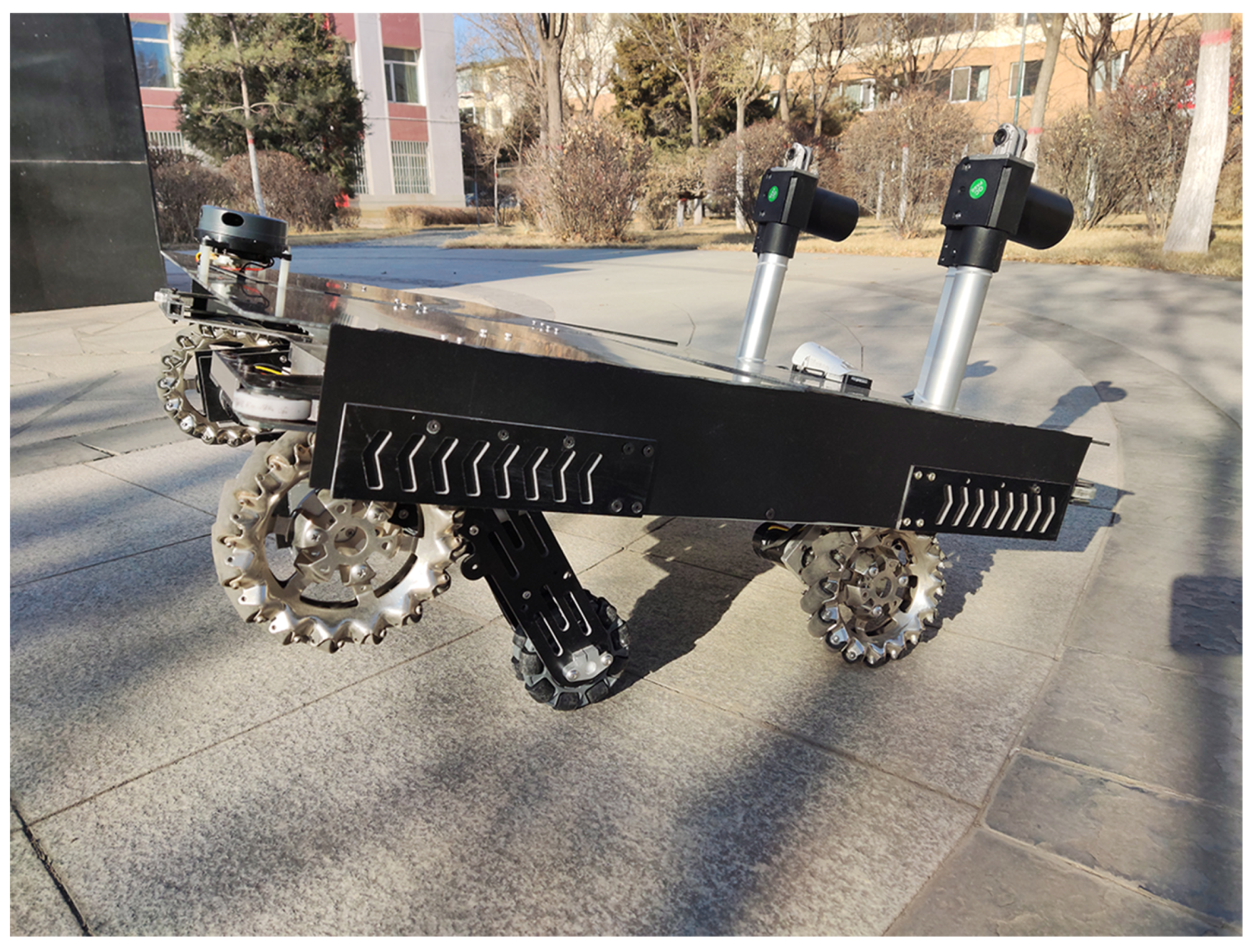
3.2. Prototype Platform
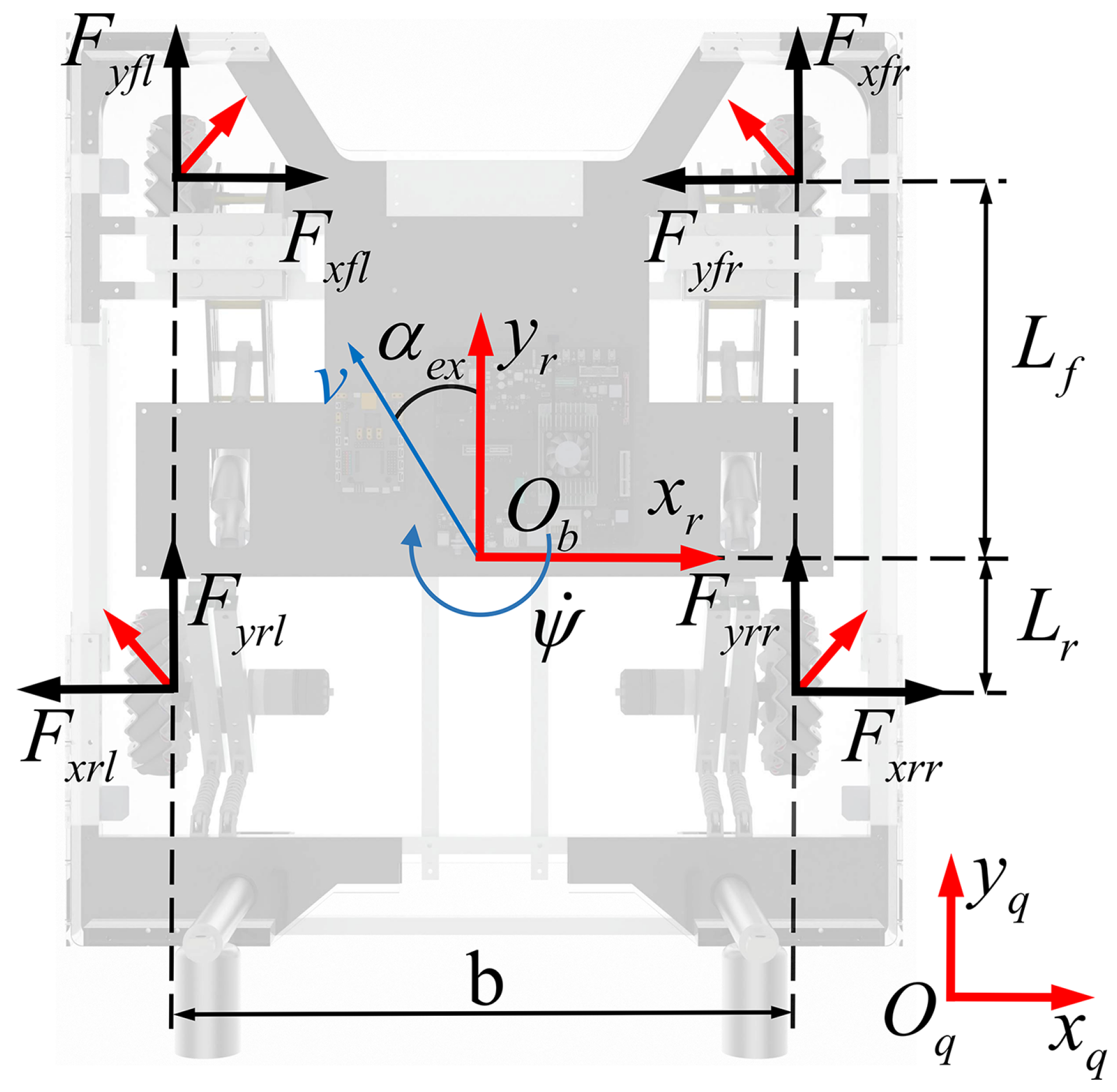
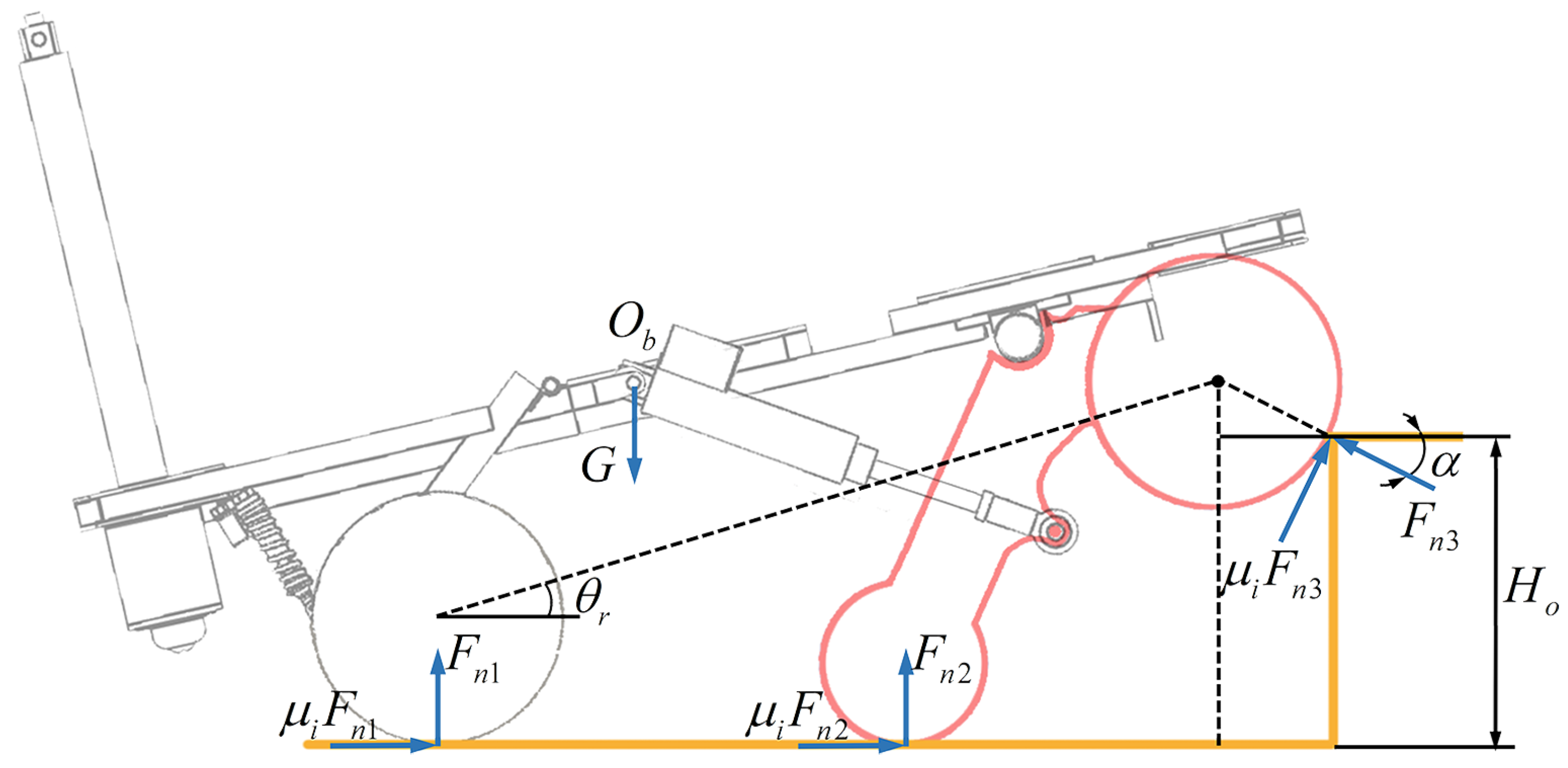
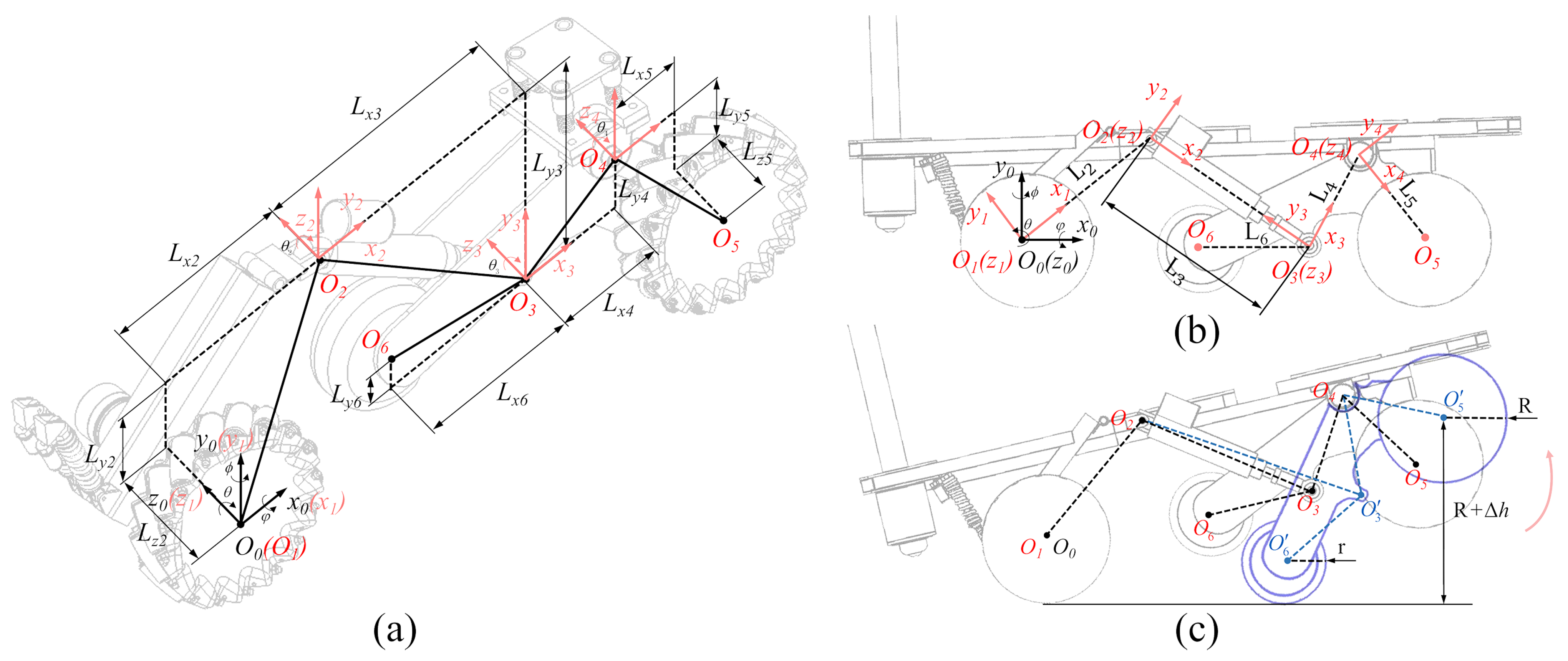
The overall design concept of the robot is compact, simple, reliable, and practical. A novel agile obstacle-overcoming robot is shown in Figure 3. The robot has a front and rear lifting structure and omnidirectional moving ability. With the design of machinery, the robot can overcome obstacles up to 234.4 mm by deformation methods (approximately 3.2 times the wheel radius). The front lifting mechanism is fitted with an independent suspension at the body joint, effectively reducing body vibration. The structure of the swing arm is similar in shape to a triangle and relies on an electric putter for its movement. We used putters instead of motors to drive the swing arms at the joint of the arms and body because it would reduce the load capacity of the robot. The swing arm mechanism was fitted with a Mecanum wheel and an omnidirectional wheel. Mecanum wheels are used as drive wheels and are typically in contact with the ground. The omnidirectional wheel is a driven wheel that can be retracted and does not contact the ground.
In general, individual omnidirectional wheels or Mecanum wheels are not continuous contact with the ground during movement. The structure of the wheels causes the robot to experience a degree of high-frequency vibrations. It is because many small driven rotors around the wheel are not continuous. Increasing the number of wheels in contact with the ground can improve this problem. Therefore, swing arms can be used as active suspensions. The robot moved in a six-wheeled landing stance by controlling the front putters. Omnidirectional wheels do not affect the movement of the Mecanum wheels when in contact with the ground. Redundant support points enable robot stability on flat and sloping surfaces. However, we did not adopt this approach because of the high real-time requirements of the control and the floating data of the sensors caused by tiny vibrations.
The control and decision-making of the robot rely on the control module and processor. There are four cameras and one stereo camera on the robot. The overall motion strategy based on the perception equipment is introduced in Section 4. Nearly all the electronic components and structures are inside the robot. There is a completely flat surface on the upper surface of the robot with an area of approximately 0.5 m 2 . The upper surface of the robot is 274 mm above ground. Moreover, the shallow centre of gravity allows additional actuators to be deployed in the robot. The robot can steadily perform any everyday work when less than a 30 kg load. At this point, we only placed a radar for simple map-building and obstacle avoidance. A more sophisticated perception and mapping system should be investigated in the future.
Based on the design, the robot retains the agility of an omnidirectional robot and the reliable and fast capability of overcoming obstacles. For a reasonable model, the other vital parameters are summarized in Table 1.

3.3. Modelling

When the robot is in motion mode, its kinematic model is similar to a conventional robot with four Mecanum wheels [37]. This study analyzed the kinematic relationships of the robot, particularly the swing arms. It is assumed that the left and right swing arms are perfectly symmetrical and that the masses are uniform and equal. In addition, all robot structures are rigid and do not deform owing to their load and envelope properties. The coordinate system using the D-H method is shown in Figure 4a. During movement and deformation, no part of the system O n x n y n z n ( n = 1 , 2 , 3 , 4 , 5 , 6 ) is displaced along the z-axis. The approximate coordinate system is shown in Figure 4b. The height of the front wheel lift can be expressed as R + h . The opposite side swing arm can be calculated in the same manner. The relationship matrix for each key part of the robot is as follows:
m T n = cos θ n sin θ n 0 L x m n sin θ n cos θ n 0 L y m n 0 0 1 0 0 0 0 1
where m T n denotes the relative position of coordinate system O n x n y n z n ( O n ) with respect to coordinate system O m x m y m z m ( O m ) . θ n indicates the angle of the coordinate system O n with respect to the coordinate system O n 1 around the z n -axis. L x m n and L y m n denote the distances along the x 0 and y 0 axes, respectively, of the message On with respect to the coordinate system O m . Owing to the telescopic transformation of the front putter, L x 23 and L y 23 can be expressed as:
L x 23 = D + Δ l r cos θ 2 θ 1 L y 23 = D + Δ l r sin θ 2 θ 1
where D denotes the initial length of the front electric actuator. l r denotes the length of the front electric putter extension. Figure 4c shows the robot lifting the front wheels. The dashed black line shows the position of each coordinate system without lifting. The dashed blue line shows the position of each coordinate system when the front wheel is lifted. T/he robot lifting process over obstacles is divided into two stages. Before the slave wheel contacts the ground, it is in the first stage. The driven wheel moves from the suspended state to the ground during this period. The relative displacement of coordinate system O 5 with respect to coordinate system O 0 in the y 0 direction does not change. Therefore, the kinematic model in this phase has a unique solution. The second stage is the front-wheel lift stage. The relative displacement of coordinate system O 6 with respect to the coordinate system O 0 in the y 0 direction does not change. Therefore, the kinematic model provides a unique solution for this stage. The transformation matrix of the robot’s front Mecanum wheel can be expressed as 0 T 5 = 0 T 1 θ 1 1 T 2 θ 2 2 T 3 θ 3 3 T 4 θ 4 4 T 5 θ 5 , where
0 T 5 = c ϕ 1 S ϕ 1 0 L x 1 S ϕ 1 c ϕ 1 0 L y 1 0 0 1 0 0 0 0 1
The transformation matrix of the driven wheel is expressed as 0 T 6 . The transformation matrix 3 T 6 represents the pose relationship from the coordinate systems O 6 to O 3 . Therefore, the relative angle relationship is a fixed value θ γ and 0 T 6 can be expressed as 0 T 6 = 0 T 1 θ 1 1 T 2 θ 2 2 T 3 θ 3 3 T 6 θ γ , where
0 T 6 = c ϕ 2 S ϕ 2 0 L x 2 S ϕ 2 c ϕ 2 0 L y 2 0 0 1 0 0 0 0 1
In the first stage, the coordinate system O 6 does not change in the y 0 -axis direction. Therefore, the posture at the end of the first phase is used as the initial posture for the second phase. Let f ( x ) 4 × 1 = L x 2 h r r L y 1 L x 1 T , where h r = R + h . Then, the location of the key coordinate system for the first stage can be expressed as
f ( x ) 4 × 1 = L 6 c γ + D + Δ l r c 12 + L 2 c 1 L 6 s γ + D + Δ l r s 12 + L 2 s 1 L 5 s 1234 + L 4 s 123 + D + Δ l r s 12 + L 2 s 1 L 5 c 1234 + L 4 c 123 + D + Δ l r c 12 + L 2 c 1
where c 1 n and s 1 n are abbreviations for cos θ 1 + + θ n and sin θ 1 + + θ n . The relationship between h and l r can be determined using Equations (3) and (4). Meanwhile, the displacement of the front wheel and the driven wheel in the direction of the y 0 axis can be expressed as h h r r T = L y 1 L y 2 T . h and h r r can be represented by a matrix of relations. From (1) to (5), the relationship between h and l r can be solved using the following equation
Δ h h r r L x 1 L x 2 = L 4 c 1234 + D + Δ l r c 123 + L 2 c 12 + L 1 c 1 L 5 c γ + D + Δ l r c 123 + L 2 c 12 + L 1 c 1 L 5 c 1234 + L 4 c 123 + D + Δ l r c 12 + L 2 c 1 L 6 c γ + D + Δ l r c 12 + L 2 c 1
The robot consists of four Mecanum wheels and two omnidirectional wheels. The driven roller outside the Mecanum wheel is inclined at a constant angle( 45 ). Four Mecanum wheels are torqued using independent DC motors. Derivation of the robot’s dynamics model using the Newton–Euler method, including during planar and motion of overcoming obstacles. To derive the motion equation, we assume that the global coordinate system is O q . Let the robot moving coordinate system O b coincide with the robot’s centre of gravity, and the body mass be M. According to Newton’s second law, the equation of motion (Figure 5) in the global coordinate system can be expressed as
M 0 0 M x ¨ q y ¨ q = F q x F q y T
q T r is the rotation matrix of the robot movement coordinate system O b in the yaw direction. P q = x q y q T and F q = F q y F q y T are the positioning vector and moment vector in the global coordinate system O q , respectively. By rotating the matrix equation, (7) is reduced to
M 0 0 M q T r ( ψ ) P ¨ r + q T r ( ψ ) P ˙ r = q T r ( ψ ) P r
At this point, the position–moment relationship through the transformation matrix can be expressed as P ˙ q = q T r ( ψ ) P ˙ r versus F q = q T r ( ψ ) F r , (8) can be expressed as
M 0 0 M · q T r ( ψ ) 1 · q T r ( ψ ) P ¨ r + q T r ( ψ ) P ˙ r = q T r ( ψ ) 1 · q T r ( ψ ) P r
where
q T r ( ψ ) 1 · q T r ( ψ ) T = ψ ˙ 0 1 1 0
q T r ( ψ ) 1 = q T r ( ψ ) T
From (7)–(11), (11) can be expressed as
M 0 0 M x ¨ r ψ ˙ y ˙ r y ˙ r + ψ ˙ x ˙ r = F x r F y r μ x x ˙ r μ y y ˙ r
where μ x is the linear friction coefficient along the direction of x r axis. μ y is the linear friction coefficient in the direction of the y r axis. F x r and F y r are the decoupling forces along the x r and y r axes, respectively. In turn, the Euler equation in (12) can be rewritten as
I q ψ ¨ = I r μ z ψ ˙
I r is the moment of the robot and I q is the moment of inertia of the robot. μ z denotes the linear friction coefficient of the robot in the z r direction. Considering the motor dynamics model with each wheel driven independently, the driving force generated by the motor can be expressed as
F i = k w R R a · u i k w k e n R 2 R a · R θ ˙ i
Because i = f r , f l , r l , r r , F i indicates the forces on the right front, left front, left rear and right rear Mecanum wheels, respectively. k w / R R a and k w k e n / R 2 R a are the motor correlation coefficients. Where R is the wheel radius, k w is the motor torque factor, k e is the back EMF factor of the motor, and n indicates the motor reduction ratio. The combined force of the robot in the horizontal direction and I r can be expressed as follows:
F x r = F f r + F f l F r l + F r r / 2
F y r = F f r + F f l + F r l + F r r / 2
I r = F f r F f l F r l + F r r · b / 2 + F f r F f l F r l + F r r · L f + L r / 4
By substituting ( 14 ) into ( 17 ) in ( 12 ) and ( 13 ) , equivalent kinetic equations for the horizontal motion of the robot can be obtained.
The four Mecanum wheels remain as support and drive wheels during obstacle crossing of the robot. There are also two omnidirectionally driven wheels as supports to assist in overcoming this problem.
The front wheels of the robot overcome the obstacle, as shown in Figure 6. In the figure, H 0 denotes the height of the obstacle, and α denotes the angle of the regular contact force between the front wheel and obstacle in the horizontal direction. F n i denotes the support of the structure by the ground, and m u i denotes the linear coefficient of friction of the pavement. O b indicates the centre of mass of the barrier-crossing robot. At this point, the robot dynamics equation is expressed as:
M ( q ) · q ¨ = F q f q + F e
m u x i , m u y i , and m u z i ( i = f r , f l , r l , r r ) represent the linear coefficients of friction along the three axes of the global coordinates, respectively. F x i , F y i , and F z i represent the decoupling forces along the x-axis, y-axis and z-axis, respectively. The robot is exposed to external forces or single-wheel contact obstacles when crossing them. This may cause it to be exposed to yaw-directional forces. Assume a lateral disturbance force F e at a distance L h from the leading edge. The Euler equations for the yaw ψ and pitch θ directions can be expressed as
I q ψ ¨ = I r I q θ ¨ + b · F e cos ϕ e L f L h · F e sin ϕ e
I q θ ¨ = μ z θ ˙ r
In this case, the angular velocity in the pitch direction is determined by three parameters. They are the decoupling force of the robot along the axis direction, the external force and the linear friction coefficient in the tangential direction of the pitch. The combined force of the robot in the three-axis direction can then be expressed as
F x r = F f r + F f l F r l + F r r f n o r f n o l / 2
F y r = F f r + F f l · cos α + F n l + F r r f nor f nol 2
F z r = μ f r F y r + μ f l F y r · sin α / 2 I q θ ¨ / L r cos θ r
Moreover, I r can be expressed as
I r = F f t F f f F r l + F r r F o r F o l · b / 2 + F f t F f l F r l + F r r F a r F a l · L f + L r / 4
Substituting ( 14 ) to ( 17 ) and ( 21 ) to ( 24 ) can obtain the kinetic model of the robot’s obstacle overcoming process.
M M M M ( q ) x ¨ r y ¨ r z ¨ r q ¨ = F x r F y r F z r F q μ x i x ˙ r μ y i y ˙ r μ z i z ˙ r f q + F e cos ϕ e F e sin ϕ e 0 F e
In this case, overcoming of obstacles is determined by the robot’s pose planning and the ground friction coefficient. The following constraints must be met
H Δ l r , μ i H 0 H θ r

4. Methodology for Overcoming Obstacles

4.1. Heterogeneous Sensing System

In Section 3, we model the critical overcoming state of the robot. Some scholars studied the friction coefficient and control of omnidirectional mobile robots using the methods of machine learning or friction compensation control [38,39]. The road friction coefficient and height of the front-wheel lift are critical points for the robot to overcome obstacles successfully and smoothly. However, a lack of research considered friction coefficient for obstacle-overcoming robots. Once the robot acquires data about the obstacle, it must decide the pattern and control. We expect to use a variety of sensory sensors to establish a heterogeneous sensing system to obtain data and use it as a basis for decision-making.
In this study, the robot operating environment is divided into four scenarios based on the road conditions and linear friction coefficients (Table 2). They are compact surfaces, loose surfaces, snow surfaces, and ice surfaces [40]. On dry roads, the friction coefficient does not correlate significantly with speed when the robot’s speed increases slightly below 20 km/h. The friction coefficient decreases when the road is damp but mainly depends on speed. In the case of waterlogging, the friction coefficient decreases as the water level increases. Robots cannot work in such environments; therefore, they are not discussed in this paper. Each condition has a different friction coefficient when it is dry or damp. Tight surfaces are the most common environments for scenes, such as cities and factories. Loose surfaces are commonly found in wilderness environments and are rarely observed in urban and industrial settings. Overcoming the problems of wilderness search and rescue is a challenge. The Mecanum wheel does not work well on loose surfaces. Furthermore, the friction coefficient of the ice surface is also low, and the temperature of the ice surface heavily influences it. The coefficient of friction reaches its lowest value when the surface temperature is close to 0 °C.
Different robots have different strategies for controlling and making decisions while overcoming obstacles. However, the commands for robots are primarily provided by remote operators based on experience, which can be attributed to the lack of intelligence and environmental perceptual abilities. However, it is possible to achieve functionality during obstacle overcoming in simple strategies, such as deforming to the maximal scale to overcome any obstacles or raising the structures above the obstacle. Either way, robots consume more time and energy and run the risk of failure. In addition, various road conditions and temperatures can significantly impact obstacle crossing. When a robot is faced with a complex operating environment, the appropriate deformation parameters are critical to the speed and smoothness of the modal transition.
It is difficult to obtain the environmental linear friction coefficient directly. Scholars estimate the coefficient of friction through other elements such as touch, current, and temperature [41,42,43]. The road conditions can be classified by the deep learning network robustly in this study. So we designed a heterogeneous sensing system geared toward the process of crossing obstacles (Figure 7). The critical parameters of obstacle crossing are solved using the deployed sensors and dynamic models to replace the operator for command issuance. The proposed system is based on the temperature sensors, load cells, stereo camera, pavement acquisition camera, and calculation unit described in Section 2 to implement the functions. We still use the traditional autonomous driving perception system for perceptual data acquisition in motion mode, and the robot is the same as a typical mobile robot. Lidar and stereo camera can perform mapping and locating missions.
After entering the obstacle crossing mode, the robot moved at a speed of 0.25 m / s . The distance between the obstacle and the robot D 0 and the height of the obstacle H 0 were acquired using a stereo camera. The road conditions of the respective wheels were acquired using surface acquisition cameras. Images of the road environment were extracted at 20 fps. They were fed into the computing unit, which relied on the trained YOLOX-Nano model for classification. YOLOX is a target detection model proposed by the Megvii Technology Corporation, based on YOLO-v3. The lightweight model maintained a high accuracy rate while maintaining the speed of computing [44]. In addition to classifying the road surface, the model is also used to detect small obstacles and step edges. The dryness and wetness of snow and ice do not have distinctive characteristics and have little influence on the friction coefficient. Therefore, in the production of datasets, snow and ice conditions were not distinguished between dry and wet conditions. In this study, the model was trained using ten classifications of familiar scenes from self-collected scenes with 12,328 images. We use Mean Average Precision (mAP) and Intersection Over Union (IoU) to evaluate the model. The model achieved mAP = 89.8 % at IoU = 0.5 . The system suppresses the newly acquired 10-frame image results with nonextreme values. The highest category of confidence level accumulation was the result. This method was designed to prevent unstable mutations that could interfere with the results. The ambient temperature T and load G l were obtained simultaneously using the temperature sensor and load cell. The total mass G was determined from the weight of the robot G b and load G l . At this point, the dynamic model, temperature, and load are combined to obtain the corresponding pavement friction coefficient μ i ( i = f r , f l , r l , r r ) . Using G, μ i , and T as inputs, we substitute into Equation (25) to obtain the lift height h . As shown in Equation (6), there is a correspondence between h and l r . We can calculate the rate of the front putter v p using H 0 and D 0 . After the front wheels have completed the crossing, the rear lifting mechanism normally lifts according to the obstacle’s height. The perceptual data acquirement assisted the entire process.

4.2. Overall Motion Strategy

The robot benefited from the perception data system and used a top-down strategy based on abstract commands. Figure 8 shows the overall motion strategy of the robot, consisting of an Order Layer, a Decision-making Layer, and a Behaviour Layer. The command layer mainly provides abstract motion commands such as move, rotate, pan, and cross. The heterogeneous sensing system is primarily aimed at assisting the motion strategy of the crossing process. The operator provides other motion commands at a given distance. In the future, robots can perform more integrated and autonomous tasks when equipped with sufficient intelligence to detect and decide. The order layer converts high-level motion commands into control parameters, such as the height of obstacles H 0 , friction coefficient μ i , angular velocity of wheels ω , steering angle δ , and speed of the putters v i . The factors above are input in the decision-making layer.
When overcoming obstacles, the heterogeneous sensing system estimates the road friction coefficient in the decision-making layer. For the motion mode, the robot can complete basic control based on G, ω , δ , and μ i . The key points for overcoming the mode are G, H 0 , μ i , and v i . The desired information enters the PD dual-loop controller in the respective modes.
The decision-making layer communicates and feeds back with the behaviour layer to rapidly control the actuators.

5. Experiments and Discussion

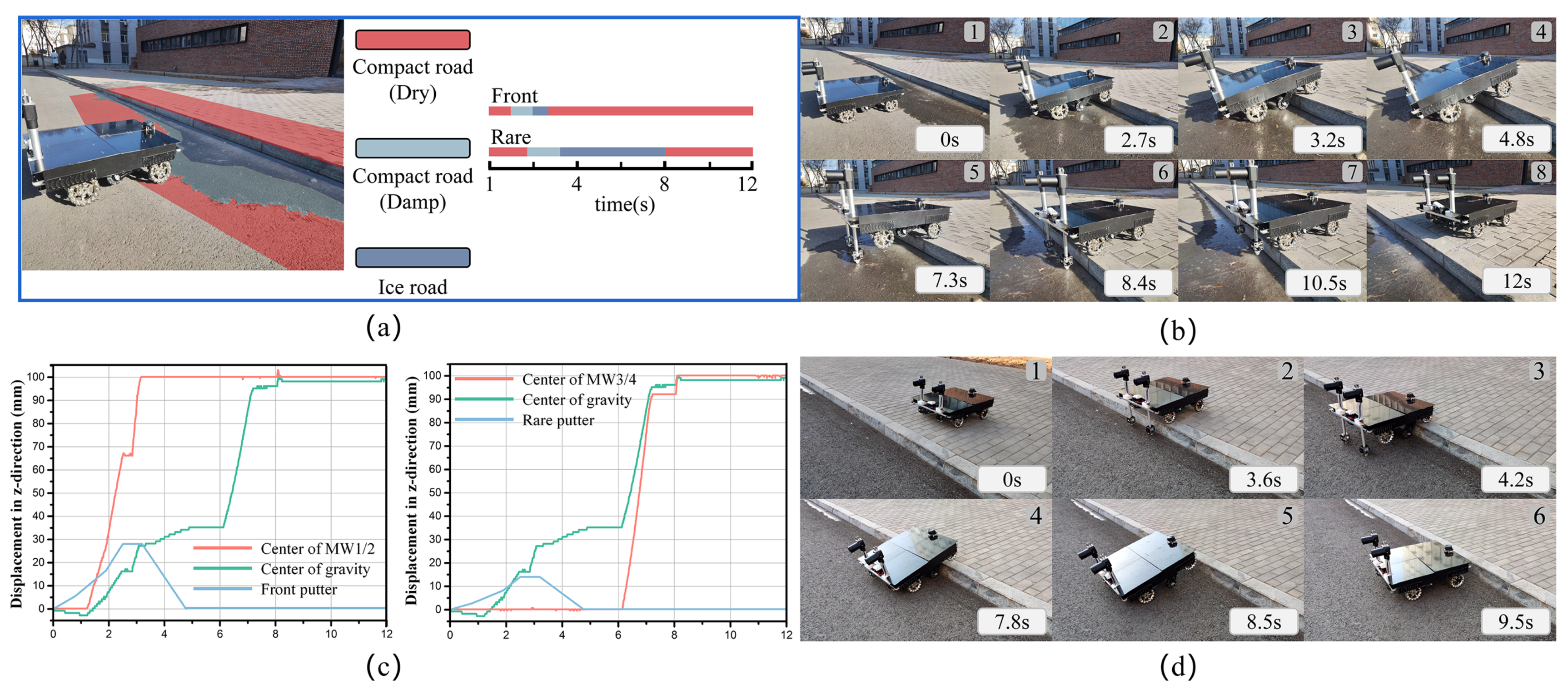
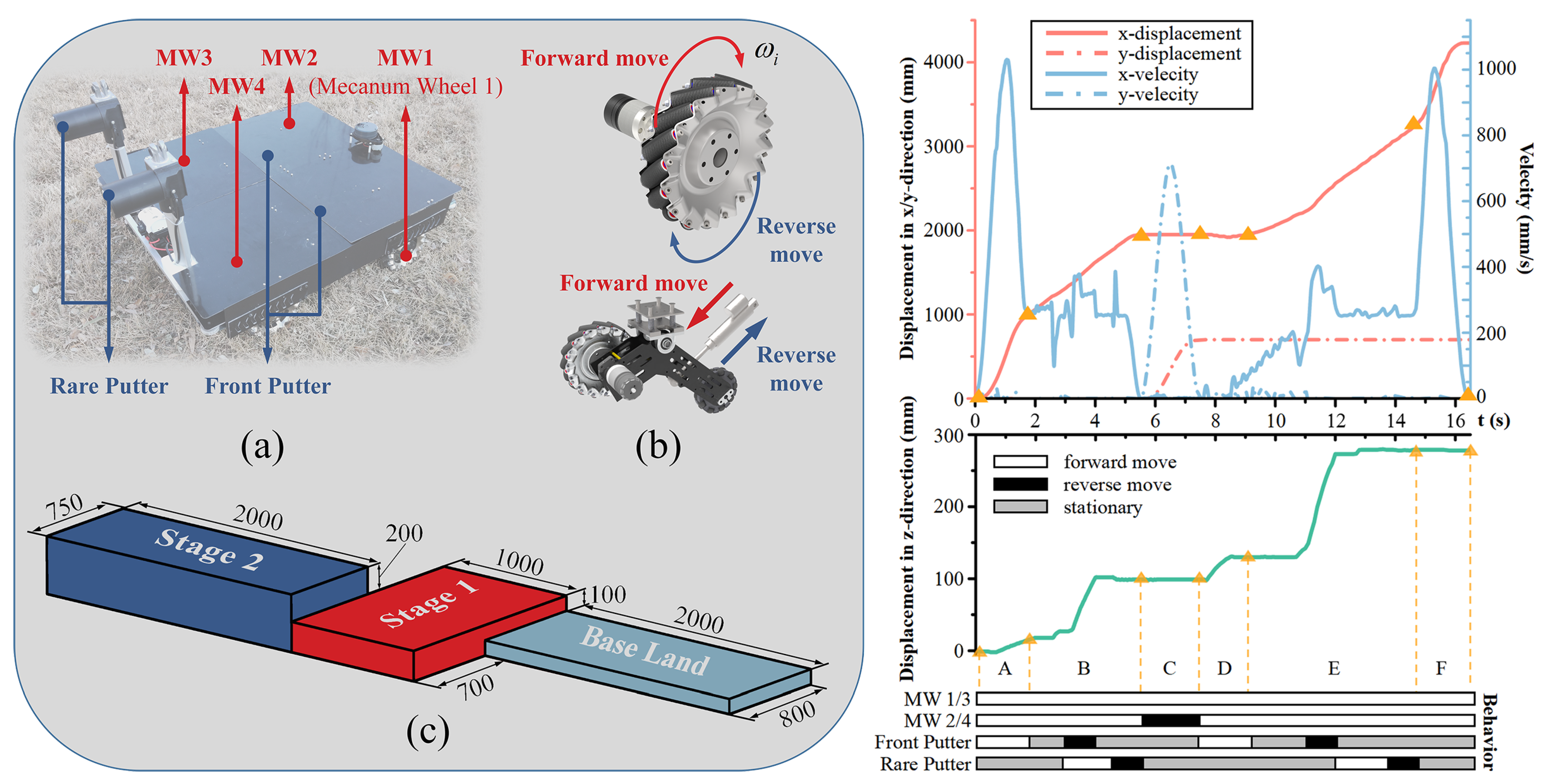
5.1. Simulation of Motion and Continuous Obstacles Overcoming

We built a virtual prototype to verify the ability of the robot to move flexibly and overcome obstacles continuously. Furthermore, our team simulated the robot in a narrow environment at high speed, variable speed, and continuous obstacle crossing. The actuators of the robot are referred to by the labels in Figure 9a. The Mecanum wheels are represented by M W i ( i = 1 , 2 , 3 , 4 ) . Putters were divided into front and rear putters. We specified the orientation of the wheels and putters to describe the motion of the robot accurately in Figure 9b. When the Mecanum wheel is viewed from the robot’s right side, the clockwise rotation is the forward motion, and the counterclockwise rotation is the reverse motion. The putter is extended outwards for forward motion and contracted inward for reverse motion. The simulation test environment is illustrated in Figure 9c. The ground was divided into base land, stage 1, and stage 2, all with a friction coefficient of 0.9. The widths of the base land, stage 1 and stage 2 were 800 mm, 1000 mm, and 750 mm, respectively. This implies that it is difficult for a typical wheeled overcome robot to steer and pass. The height of Stage 1 was 100 m, and the height of Stage 2 was 200 mm. The simulation process and results are as follows.
Figure 9 shows the simulation results for the motion settings. We divided the simulation process into steps A–F according to the key stages and labelled the behaviour of the robot’s main actuators. In step A, the robot was tested with an acceleration of 1.2 m / s 2 from 0 s to 1 s, followed by a deceleration to 0.25 m / s within 1 s. The front putters move forward during the robot’s acceleration, depending on the height and distance from Stage 1. The robot demonstrated positive variable-speed performance and dynamic stability during this process. In Step B, the robot maintained 0.25 m / s to overcome Stage 1. After the front wheels crossed Stage 1, the front putters reversed, whereas the rear actuator made a forward movement. This step completes the retraction of the front part and lifting of the rear part. At this point, the robot moved forward at a low speed. When the rear wheels covered Stage 1, the rear putters made a reverse movement to overcome Stage 1. The robot then panned from the right side to the left side of Stage 1 in Step C. During the process, the robot completed a variable-speed movement in the y-axis horizontal direction at an acceleration of 0.8 m / s 2 . Step D and E are similar to Step A and B, respectively. These two steps completed the overcoming of Stage 2 at 200 m height. Step F performs variable-speed motion until it reaches the end and remains stationary.
In the simulation experiments, the robot could perform smooth motion articulation owing to the knowledge of the environment. The robot achieved efficient and stable movement and obstacle crossing, verifying its dynamic and obstacle crossing performance. However, we chose to move and overcome obstacles in stages during the platform tests because of the high variability of complex unstructured scenarios. Such smooth movements, determined based on testing and experience, are difficult to achieve. An immature motion-planning scheme with an incomplete perceptual system increases the risk of failure in crossing an obstacle.

5.2. Experiments of Overcoming Obstacles

We built a platform to verify the performance of the robot. First, our team performed basic mobility tests on a flat surface. The robot has a maximum speed of 5.2 m / s and a maximum acceleration of 1.5 m / s 2 with a four-wheel drive. With the front wheels lifted and relying on a two-wheel drive, the robot had a maximum speed of 3.8 m / s and a maximum acceleration of 1.2 m / s 2 . See Table 1 for additional key information. In addition, we tested the robot for dynamic stability. When the front wheels of the robot were lifted, the omnidirectional wheels and rear wheels supported the robot’s structure. The robot started to decelerate at an initial speed of 1.5 m/s. With the rear wheels locked, no posture causes the robot’s centre of gravity to become unbalanced.
To verify the effectiveness of the robot’s heterogeneous sensing system, we conducted tests on obstacle crossing in complex environments. Figure 10a shows the setting for the overrun test. The barrier height was 10 cm, and the surfaces were dry compacted, damp compacted, and ice surfaces. The outside air temperature is 0 degrees, and the robot does not have any load. The perceptual data correspond to time on the right side of Figure 10a. These data were used to optimize the robot’s obstacle-overcoming process. Figure 10b and Figure 10c show the sequence and results of the experiment, which takes 12 s throughout. Based on the acquired road conditions and temperature, the front putters’ speed underwent two times changes during the forward motion to ensure raising higher heights at the same time. Therefore, the robot lifted sufficient height on the ground. Meanwhile, the robot climbed the obstacle at a 0.25 m / s speed.
The robot can rely on its suspension system to descend from the obstacles. However, considering that the robot may be equipped with a wealth of equipment to perform different jobs in the future, we also tested a smooth descent process. Figure 10d shows the robot descending from an obstacle. The entire descent took 9.5 s and was a reverse operation for overcoming obstacles. In Step 4, only the front putters must be fully extended to ensure the stability of the robot’s support. These experiments demonstrate that the robot can move and overcome obstacles smoothly and flexibily.

5.3. Discussion and Future Works

Robots with different structures, perception conditions and usage scenarios are difficult to evaluate quantitatively. We discuss the platform with existing robots from several vital points. In terms of the attitude stability, ability to move, and obstacle overcoming, the platform has a gentler attitude than most wheeled and crawler mobile robots. However, compared with platforms such as quadruped robots, it is still unable to maintain the whole level of the trunk posture. Meanwhile, the platform has significant advantages over crawler and quadruped robots in mobility. Nevertheless, it will be greatly limited in complex and uneven scenes. The heterogeneous sensing system and the overall control strategy optimized the control of the obstacle overcoming process. Detecting the road surface environment can effectively classify and estimate the linear friction coefficient. At the same time, the obstacle crossing parameters are solved by combining the robot load, ambient temperature and dynamic model. However, due to the limitation of the type and number of training sets, it is still unable to adapt to all situations.
We hope to improve the robot’s rear rising mechanism to enrich its deformation capabilities in the future. In addition, we will enhance the perception ability and obtain comprehensive environmental information. At the same time, more combinations and tests of heterogeneous sensing systems will be carried out. This can effectively improve the motion planning ability of the robot. Based on the robot, we will invest in a three-dimensional path-planning algorithm. Robots could carry actuators to perform tasks autonomously in complex scenarios in the future.

6. Conclusions

In this paper, we report a novel wheeled robot. The concept of the robot originates from humans overcoming obstacles and planetary robots. However, swing arms can be actively deformed by rotating about the connecting joint to lift omnidirectional wheels instead of landing on six wheels, such as a planetary robot. Mecanum wheels were combined with the swing arms and omnidirectional wheels, considering the principles of wheel motion and overcoming obstacles. The low centre of gravity and flat upper surface render the robot extremely expandable. Numerous sensors and actuators can be matched on the upper surface, enabling the robot to perform various tasks in a complex environment.
In addition, a heterogeneity sensing system was presented. The road surfaces were classified using the YOLOX-Nano network. The control expectations of the robot were optimized by comprehensively considering factors such as the temperature, quality, and motion parameters. Meanwhile, we designed an overall motion strategy based on the heterogeneity system. The overall motion strategy combines the friction coefficient with a kinetic model to make the robot’s motion ability flexibly.
Simulations and platform experiments confirmed the advantages of mobility and dynamic stability of the robot in different modes. The robot can move efficiently, whirl, pan, and overcome obstacles over narrow areas. Compared with the four-wheel movement, the six-wheel support, including the omnidirectional wheels, can effectively reduce the high-frequency vibration of the robot on a flat surface. Robots can also overcome obstacles by acquiring sensing data and considering key parameters, including the friction coefficient. The flexible mobility and reliable ability of obstacles to overcome and expandable structures prove that robots have a wide range of application prospects in the industry, inspection, environment, logistics, and other fields.

Author Contributions

Conceptualization, Y.H.; methodology, Y.H. and J.Y.; software, Y.H. and Z.Z.; validation, Y.H., J.Y. and Z.Z.; formal analysis, R.M.; investigation, Y.H.; data curation, J.Y. and Z.Z.; writing—original draft preparation, Y.H.; writing—review and editing, Y.H., R.M. and X.Z.; supervision, R.M. and X.Z.; project administration, R.M., X.Z.; funding acquisition, X.Z. All authors have read and agreed to the published version of the manuscript.

Funding

This research received no external funding.

Data Availability Statement

The data presented in this study are available on request from the corresponding author.

Conflicts of Interest

The authors declare no conflict of interest.

References

  1. Rubio, F.; Valero, F.; Llopis-Albert, C. A review of mobile robots: Concepts, methods, theoretical framework, and applications. Int. J. Adv. Robot. Syst. 2019, 16. [Google Scholar] [CrossRef] [Green Version]
  2. Kuwada, A.; Wakimoto, S.; Suzumori, K.; Adomi, Y. Automatic pipe negotiation control for snake-like robot. In Proceedings of the IEEE/ASME International Conference on Advanced Intelligent Mechatronics, AIM, Xi’an, China, 2–5 July 2008; pp. 558–563. [Google Scholar] [CrossRef]
  3. Rollinson, D.; Choset, H. Gait-based compliant control for snake robots. In Proceedings of the 2013 IEEE International Conference on Robotics and Automation, Karlsruhe, Germany, 6–10 May 2013; pp. 5138–5143. [Google Scholar] [CrossRef]
  4. Chen, J.; Liang, Z.; Zhu, Y.; Zhao, J. Improving Kinematic Flexibility and Walking Performance of a Six-legged Robot by Rationally Designing Leg Morphology. J. Bionic Eng. 2019, 16, 608–620. [Google Scholar] [CrossRef]
  5. Lee, Y.H.; Lee, Y.H.; Lee, H.; Phan, L.T.; Kang, H.; Kim, U.; Jeon, J.; Choi, H.R. Trajectory design and control of quadruped robot for trotting over obstacles. In Proceedings of the 2017 IEEE/RSJ International Conference on Intelligent Robots and Systems (IROS), Vancouver, BC, Canada, 24–28 September 2017; pp. 4897–4902. [Google Scholar] [CrossRef]
  6. Park, H.W.; Chuah, M.Y.; Kim, S. Quadruped bounding control with variable duty cycle via vertical impulse scaling. In Proceedings of the 2014 IEEE/RSJ International Conference on Intelligent Robots and Systems, Chicago, IL, USA, 14–18 September 2014; pp. 3245–3252. [Google Scholar] [CrossRef]
  7. Park, H.W.; Wensing, P.M.; Kim, S. Jumping over obstacles with MIT Cheetah 2. Robot. Auton. Syst. 2021, 136, 103703. [Google Scholar] [CrossRef]
  8. Seok, S.; Wang, A.; Chuah, M.Y.; Otten, D.; Lang, J.; Kim, S. Design principles for highly efficient quadrupeds and implementation on the MIT Cheetah robot. In Proceedings of the 2013 IEEE International Conference on Robotics and Automation, Karlsruhe, Germany, 6–10 May 2013; pp. 3307–3312. [Google Scholar] [CrossRef]
  9. Bajracharya, M.; Ma, J.; Malchano, M.; Perkins, A.; Rizzi, A.A.; Matthies, L. High fidelity day/night stereo mapping with vegetation and negative obstacle detection for vision-in-the-loop walking. In Proceedings of the 2013 IEEE/RSJ International Conference on Intelligent Robots and Systems, Tokyo, Japan, 3–7 November 2013; pp. 3663–3670. [Google Scholar] [CrossRef]
  10. Li, C.; Liu, D.; Liu, B.; Ren, X.; Liu, J.; He, Z.; Zuo, W.; Zeng, X.; Xu, R.; Tan, X.; et al. Chang’E-4 initial spectroscopic identification of lunar far-side mantle-derived materials. Nature 2019, 569, 378–382. [Google Scholar] [CrossRef] [PubMed]
  11. Grotzinger, J.P.; Crisp, J.; Vasavada, A.R.; Anderson, R.C.; Baker, C.J.; Barry, R.; Blake, D.F.; Conrad, P.; Edgett, K.S.; Ferdowski, B.; et al. Mars Science Laboratory Mission and Science Investigation. Space Sci. Rev. 2012, 170, 5–56. [Google Scholar] [CrossRef] [Green Version]
  12. Zhang, J.; Yang, W.; Hu, S.; Lin, Y.; Fang, G.; Li, C.; Peng, W.; Zhu, S.; He, Z.; Zhou, B.; et al. Volcanic history of the Imbrium basin: A close-up view from the lunar rover Yutu. Proc. Natl. Acad. Sci. USA 2015, 112, 5342–5347. [Google Scholar] [CrossRef] [Green Version]
  13. Bosworth, W.; Whitney, J.; Kim, S.; Hogan, N. Robot locomotion on hard and soft ground: Measuring stability and ground properties in-situ. In Proceedings of the 2016 IEEE International Conference on Robotics and Automation (ICRA), Stockholm, Sweden, 16–21 May 2016; pp. 3582–3589. [Google Scholar] [CrossRef]
  14. Rodríguez-Martínez, D.; Van Winnendael, M.; Yoshida, K. High-speed mobility on planetary surfaces: A technical review. J. Field Robot. 2019, 36, 1436–1455. [Google Scholar] [CrossRef]
  15. Estier, T.; Piguet, R.; Eichhorn, R.; Siegwart, R. Shrimp, a Rover Architecture for Long Range Martian Mission. In Proceedings of the Sixth ESA Workshop on Advanced Space Technologies for Robotics and Automation (ASTRA’2000), Noordwijk, The Netherlands, 5–7 December 2000; pp. 5–7. [Google Scholar]
  16. Shiroma, N.; Chiu, Y.H.; Min, Z.; Kawabuchi, I.; Matsuno, F. Development and control of a high maneuverability wheeled robot with variable-structure functionality. In Proceedings of the IEEE International Conference on Intelligent Robots and Systems, Beijing, China, 9–15 October 2006; pp. 4000–4005. [Google Scholar] [CrossRef]
  17. Ning, M.; Yu, K.; Zhang, C.; Wu, Z.; Wang, Y. Wheelchair design with variable posture adjustment and obstacle-overcoming ability. J. Braz. Soc. Mech. Sci. Eng. 2021, 43, 197. [Google Scholar] [CrossRef]
  18. Candiotti, J.L.; Daveler, B.J.; Kamaraj, D.C.; Chung, C.S.; Cooper, R.; Grindle, G.G.; Cooper, R.A. A Heuristic Approach to Overcome Architectural Barriers Using a Robotic Wheelchair. IEEE Trans. Neural Syst. Rehabil. Eng. 2019, 27, 1846–1854. [Google Scholar] [CrossRef]
  19. Li, Y.; Dai, S.; Zhao, L.; Yan, X.; Shi, Y. Topological design methods for mecanum wheel configurations of an omnidirectional mobile robot. Symmetry 2019, 11, 1268. [Google Scholar] [CrossRef] [Green Version]
  20. Şahin, O.N.; Dede, M.İ.C. Investigation of longitudinal friction characteristics of an omnidirectional wheel via LuGre model. Robotica 2021, 39, 1654–1673. [Google Scholar] [CrossRef]
  21. Karamipour, E.; Dehkordi, S.F.; Korayem, M.H. Reconfigurable Mobile Robot with Adjustable Width and Length: Conceptual Design, Motion Equations and Simulation. J. Intell. Robot. Syst. Theory Appl. 2020, 99, 797–814. [Google Scholar] [CrossRef]
  22. Rauniyar, A.; Upreti, H.C.; Mishra, A.; Sethuramalingam, P. MeWBots: Mecanum-Wheeled Robots for Collaborative Manipulation in an Obstacle-Clustered Environment Without Communication. J. Intell. Robot. Syst. Theory Appl. 2021, 102, 3. [Google Scholar] [CrossRef]
  23. Lee, Y.; Yoon, D.; Oh, J.; Kim, H.S.; Seo, T.W. Novel Angled Spoke-Based Mobile Robot Design for Agile Locomotion with Obstacle-Overcoming Capability. IEEE/ASME Trans. Mechatronics 2020, 25, 1980–1989. [Google Scholar] [CrossRef]
  24. Mo, J.; Yan, Z.; Li, B.; Xi, F.; Li, Y. Study of obstacle-crossing and pitch control characteristic of a novel jumping robot. Sensors 2021, 21, 2432. [Google Scholar] [CrossRef]
  25. Wang, X.; Ge, H.; Zhang, K.; Chen, Y. System design and analysis of outdoor obstacle surmounting experiments for the robot with foldable wheels. In Proceedings of the 2019 IEEE 3rd Information Technology, Networking, Electronic and Automation Control Conference, ITNEC 2019, Chengdu, China, 15–17 March 2019; pp. 266–270. [Google Scholar] [CrossRef]
  26. Kim, Y.; Lee, Y.; Lee, S.; Kim, J.; Kim, H.S.; Seo, T.W. STEP: A New Mobile Platform with 2-DOF Transformable Wheels for Service Robots. IEEE/ASME Trans. Mechatronics 2020, 25, 1859–1868. [Google Scholar] [CrossRef]
  27. Wang, S.; Zou, M.; Dang, Z.; Chen, B.; Zhou, T.; Su, B. Modelling of flexible metal wheels for planetary rover on deformable terrain. Thin-Walled Struct. 2019, 141, 97–110. [Google Scholar] [CrossRef]
  28. Fuchs, M.; Borst, C.; Giordano, P.R.; Baumann, A.; Kraemer, E.; Langwald, J.; Gruber, R.; Seitz, N.; Plank, G.; Kunze, K.; et al. Rollin’ Justin - Design considerations and realization of a mobile platform for a humanoid upper body. In Proceedings of the 2009 IEEE International Conference on Robotics and Automation, Kobe, Japan, 12–17 May 2009; pp. 4131–4137. [Google Scholar] [CrossRef] [Green Version]
  29. Lee, D.Y.; Kim, S.R.; Kim, J.S.; Park, J.J.; Cho, K.J. Origami wheel transformer: A variable-diameter wheel drive robot using an origami structure. Soft Robot. 2017, 4, 163–180. [Google Scholar] [CrossRef]
  30. Choi, J.N.; Jeong, K.; Seo, T.W. Pol-E: Large-obstacle overcoming based on energy conversion method using an elastic link. Int. J. Control Autom. Syst. 2017, 15, 1835–1843. [Google Scholar] [CrossRef]
  31. Quaglia, G.; Maffiodo, D.; Franco, W.; Appendino, S.; Oderio, R. The Epi.q-1 hybrid mobile robot. Int. J. Robot. Res. 2010, 29, 81–91. [Google Scholar] [CrossRef]
  32. Cebollada, S.; Payá, L.; Flores, M.; Peidró, A.; Reinoso, O. A state-of-the-art review on mobile robotics tasks using artificial intelligence and visual data. Expert Syst. Appl. 2021, 167, 114195. [Google Scholar] [CrossRef]
  33. Masehian, E.; Jannati, M.; Hekmatfar, T. Cooperative mapping of unknown environments by multiple heterogeneous mobile robots with limited sensing. Robot. Auton. Syst. 2017, 87, 188–218. [Google Scholar] [CrossRef]
  34. Yun, S.H.; Park, J.; Seo, J.; Kim, Y.J. Development of an Agile Omnidirectional Mobile Robot with GRF Compensated Wheel-leg Mechanisms for Human Environments. IEEE Robot. Autom. Lett. 2021, 6, 8301–8308. [Google Scholar] [CrossRef]
  35. Patil, A.K.; Balasubramanyam, A.; Ryu, J.Y.; Chakravarthi, B.; Chai, Y.H. An open-source platform for human pose estimation and tracking using a heterogeneous multi-sensor system. Sensors 2021, 21, 2340. [Google Scholar] [CrossRef]
  36. Li, T.; Ceccarelli, M.; Luo, M.; Laribi, M.A.; Zeghloul, S. An experimental analysis of overcoming obstacle in human walking. J. Bionic Eng. 2014, 11, 497–505. [Google Scholar] [CrossRef]
  37. Alakshendra, V.; Chiddarwar, S.S. Adaptive robust control of Mecanum-wheeled mobile robot with uncertainties. Nonlinear Dyn. 2017, 87, 2147–2169. [Google Scholar] [CrossRef]
  38. Ren, C.; Li, X.; Yang, X.; Ma, S. Extended state observer-based sliding mode control of an omnidirectional mobile robot with friction compensation. IEEE Trans. Ind. Electron. 2019, 66, 9480–9489. [Google Scholar] [CrossRef]
  39. Guo, K.; Pan, Y.; Yu, H. Composite learning robot control with friction compensation: A neural network-based approach. IEEE Trans. Ind. Electron. 2019, 66, 7841–7851. [Google Scholar] [CrossRef]
  40. Chassis, T.A. The Automotive Chassis; Biddles, Guildford & Kings Lynn: Guildford, UK, 2001. [Google Scholar] [CrossRef]
  41. Márton, L.; Van Der Linden, F. Temperature dependent friction estimation: Application to lubricant health monitoring. Mechatronics 2012, 22, 1078–1084. [Google Scholar] [CrossRef]
  42. Niskanen, A.; Tuononen, A.J. Three three-Axis IEPE accelerometers on the inner liner of a tire for finding the tire-road friction potential indicators. Sensors 2015, 15, 19251–19263. [Google Scholar] [CrossRef] [Green Version]
  43. Chen, W.; Khamis, H.; Birznieks, I.; Lepora, N.F.; Redmond, S.J. Tactile Sensors for Friction Estimation and Incipient Slip Detection—Toward Dexterous Robotic Manipulation: A Review. IEEE Sens. J. 2018, 18, 9049–9064. [Google Scholar] [CrossRef] [Green Version]
  44. Ge, Z.; Liu, S.; Wang, F.; Li, Z.; Sun, J. YOLOX: Exceeding YOLO Series in 2021. arXiv 2021, arXiv:2107.08430. [Google Scholar]
Figure 1. Proposed practical, omnidirectional, and obstacle-overcoming platform rises front part.
Machines 10 00289 g001
Figure 2. Robot design concepts and support structures: (a) conceptual examples of a human climbing obstacles. (b) The critical step of the process when the robot overcomes an obstacle. (c-1,c-2) Supporting points of the robot in different postures.
Machines 10 00289 g002
Figure 3. The platform with dual swing arms and Mecanum wheels.
Machines 10 00289 g003
Figure 4. Kinematic reference frames of the robot. (a) Coordinate system of the robot’s right-side part. (b,c) The approximate coordinate system.
Machines 10 00289 g004
Figure 5. Dynamic coordinate system of the mobile robot.
Machines 10 00289 g005
Figure 6. The forces on the robot.
Machines 10 00289 g006
Figure 7. Heterogeneous sensing system and perceptual data acquisition method.
Machines 10 00289 g007
Figure 8. Top-down overall motion strategy for the robot.
Machines 10 00289 g008
Figure 9. Simulation experiment setups and results. (a) Name of each key component. (b) Setting of movement direction. (c) Simulation scene (mm).
Machines 10 00289 g009
Figure 10. Design and results of the platform overcome obstacles experiment: (a) experimental environment and perceptual data. (b) Diagram of the experimental process. (c) Experimental results. (d) The process of the robot descending from the obstacles experiment.
Machines 10 00289 g010
Table 1. Specification of the robot.
WidthBody700 mm
Wheel-to-wheel576 mm
DepthBody768 mm
Shaft-to-shaft465 mm
HeightBody564 mm
Ground-to-upper274 mm
WeightTotal18.8 kg
Body12.5 kg
Swing-arm *2.1 kg (×2)
Mecanum Wheel0.7 kg (×2)
Battery0.7 kg
PayloadWorkable load30 kg
SpeedMax. Average speed5.2 m/s
Lift HeightFront wheels234.4 mm
Rare wheels220 mm
Wheel actuatorsRotational speed4338 deg/s
Peak torque10.1 Nm
Cont. torque6.8 Nm
Reduction19:1
PutterLoad speed100 mm/s
Battery24 V—5.7 AhApprox. 40 min work time
* The quality of the wheels is included in the weight of the swing arm.
Table 2. Reference values for the coefficient of friction for different conditions.
Condition μ ( Dry ) μ ( Damp ) Notes
Compact road0.90–1.000.70–0.85Asphalt, Rubber
Brick, Concrete
Loose road0.50–0.700.45–0.60Gravel, Sand
Ash, Wasteland
Snowed road0.20–0.300.20–0.35
Ice road0.10–0.600.05–0.55 25 C to 0  C
Publisher’s Note: MDPI stays neutral with regard to jurisdictional claims in published maps and institutional affiliations.

