Article

Robot-Based Automation for Upper and Sole Manufacturing in Shoe Production

1
Korea Institute of Robotics & Technology Convergence, Pohang 37553, Korea
2
Department of Mechanical Engineering, Korea National University of Transportation, Chungju 27469, Korea
3
Department of Mechanical and Information Engineering, University of Seoul, Seoul 02504, Korea
*
Authors to whom correspondence should be addressed.
Machines 2022, 10(4), 255; https://doi.org/10.3390/machines10040255
Submission received: 20 February 2022 / Revised: 25 March 2022 / Accepted: 30 March 2022 / Published: 1 April 2022
(This article belongs to the Topic Robotics and Automation in Smart Manufacturing Systems)

Abstract

:
(1) Background: Conventional shoe manufacturing involves many processes that most workers avoid because of loud noises and harmful environments. Therefore, a robot-based shoe manufacturing system is needed to implement an automated process. (2) Aim: We propose a new robot-based shoe manufacturing automation system that includes an automatic robotic solution for replacing the manual manufacturing processes of the upper and sole. (3) Methods: For the upper manufacturing process, a new trajectory acquisition system with a digitizer and a shoe last turning device is proposed. A method to plan the robot’s tool path for roughing and cementing by industrial robot manipulators is also presented. For the sole manufacturing process, we adopted an industrial robot manipulator with a 3-D scanning system and a cementing tool. A trajectory generation algorithm for cementing the outer and inner sides of the sole by transforming 3-D information of the sole into a 6-D posture for the robot is proposed. (4) Results: All developed systems and proposed algorithms are applied to an automated production testbed, and their performances are experimentally verified. (5) Conclusions: The proposed system and methods can be applied for upper and sole manufacturing processes according to evaluation experiments in a demonstrative production line.

1. Introduction

Traditionally, the shoe manufacturing process has been labor intensive and required significant manual work by skilled workers. Conventional shoe manufacturing plants involve many processes that most workers avoid because of loud noises and hazardous substances. This unsatisfactory work environment suppresses the influx of new manpower and, at the same time, causes difficulties in retaining skilled manpower and an aging worker problem. In recent years, as footwear has become a popular fashion accessory, small-scale production of footwear has started in the industry, allowing it to cope with various and changing customer preferences. Compared with traditional shoe manufacturing plants, modern shoe factories must provide efficient and effective production with flexible manufacturing cells. Smart factory in Industry 4.0 is required to respond to a small quantity, multi-product flexible production system [1]. In a smart factory, automated processes using robots and systematic production using information management systems such as RFID are possible.
According to the structure of a shoe, the shoe manufacturing process can be broadly divided into an upper manufacturing process, a sole manufacturing process, and an assembly process, in which the upper part and the sole are bonded and shipped. In the manual production lines of upper and sole manufacturing, the worker draws a gauge line on the upper part with a white pen to mark the boundary line of the roughing and cementing area. Workers in the next process polish the upper underneath the drawn gauge line with grinders, and in the next step, workers apply the cementing adhesive onto the upper and inner bottom of the sole in the same line. All steps are conducted manually by skilled human workers, as shown in Figure 1.
The main problem in the manual process is that more than 30% of the assembly process manpower is put into the process of the bonding of soles, where the working environment is a harmful due to the adhesives. Therefore, there have been many recent studies on automation with the goal of reducing manual work to protect human workers from harmful environments. A typical commercial system is the adhesive system used in Taiwan’s ORISOL [2]. However, the system for ORISOL focused on the automation of sole manufacturing, and considerable manual work is still necessary for the upper manufacturing process. Therefore, further research is needed to automate the overall process of shoe manufacturing.
Many studies have been conducted and have reported on robot-based automation of the shoe manufacturing process [3,4,5,6,7,8,9,10,11,12,13,14]. Ding et al. proposed a methodology for measuring foot girths using a local radial basis function [3]. Molinari-Tosatti and Fassi introduced an industrial prototype machine consisting of roughing and cementing tools with a 3-DOF manipulator [4]. Hu et al. presented their work using a more advanced system based on a 3-D machine vision for object profile perception [5]. Nemec et al. developed a shoe-grinding cell using a 7-DOF industrial robot that generated a robot path based on the principle of the virtual mechanism approach [6]. Pedrocchi et al. represented the upper roughing process in a different way by designing a fuzzy logic controller [7]. In contrast, Gracia et al. introduced shoe packaging process automation based on a robot that was implemented with the viewpoint of human–robot cooperation [8,9]. Automation for gluing and spraying processes was also proposed in [10,11]. The robotic grasping problem for shoe soles has been intensively studied in footwear manufacturing [12,13]. Most research has focused on the specific process of automation or the development of a fundamental algorithm. In our previous study [14], we proposed the concept of a robot-based automation system for upper and sole manufacturing with preliminary results.
There are two major technical issues that need to be addressed for automation. In order to automate the upper manufacturing, it is necessary to measure gauge line on the 3-D curved surface for the upper part. The non-contact method such as the 3-D vision or 3-D scanning can be a solution for the extracting path. However, the multi-view images or data from the surrounding direction should be measured to extract the gauge line of the upper part. Therefore, the 3-D camera or scanning system should be installed in the additional rotating mechanism or manipulator. In addition, the complicated algorithm to exact a gauge line from raw multiple images or point clouds should be developed. X-ray fluorescence (XRF) spectrometry was also installed to identify an exact gauge line to check the difference of materials in [15]. However, a simpler method or mechanism is needed at the manufacturing site. For sole manufacturing, the adhesive should be sprayed evenly onto the inner part of the sole. The robot path generation algorithm to derive the position and orientation of the tool at the robot tip should be proposed using position information of the sole topline.
In this study, we propose a new robot-based shoe manufacturing automation system that includes an automatic robotic solution for replacing the manual manufacturing processes of the upper and sole. A task path acquisition system consisting of a 3-D digitizer and shoe last turning device was developed to measure the gauge line on the upper surface before the roughing and cementing processes. A method for converting the task path into the position and orientation in the robot coordinate system with position information acquired by the acquisition system was also proposed for roughing. The sole cementing process was implemented using a 3-D scanner that measured the XYZ positions of the sole topline from a fixed direction. The task path for sole cementing was first acquired by a 3-D scanner, and then the acquired task path with the position information was transformed into a position and orientation in robot coordinates, which were required for cementing the outer and inner soles, using the proposed algorithm. Figure 2 shows the entire manufacturing automation process proposed in this study. All developed systems and algorithms were applied to an automated production testbed, and their performances were experimentally verified.
The proposed robot-based manufacturing systems for the upper and sole are explained in Section 2 and Section 3, respectively. In Section 4, the implementation of the proposed system and computing algorithms by building a shoe manufacturing automation testbed is described. In Section 5, the conclusions, limitations, and future work are presented.

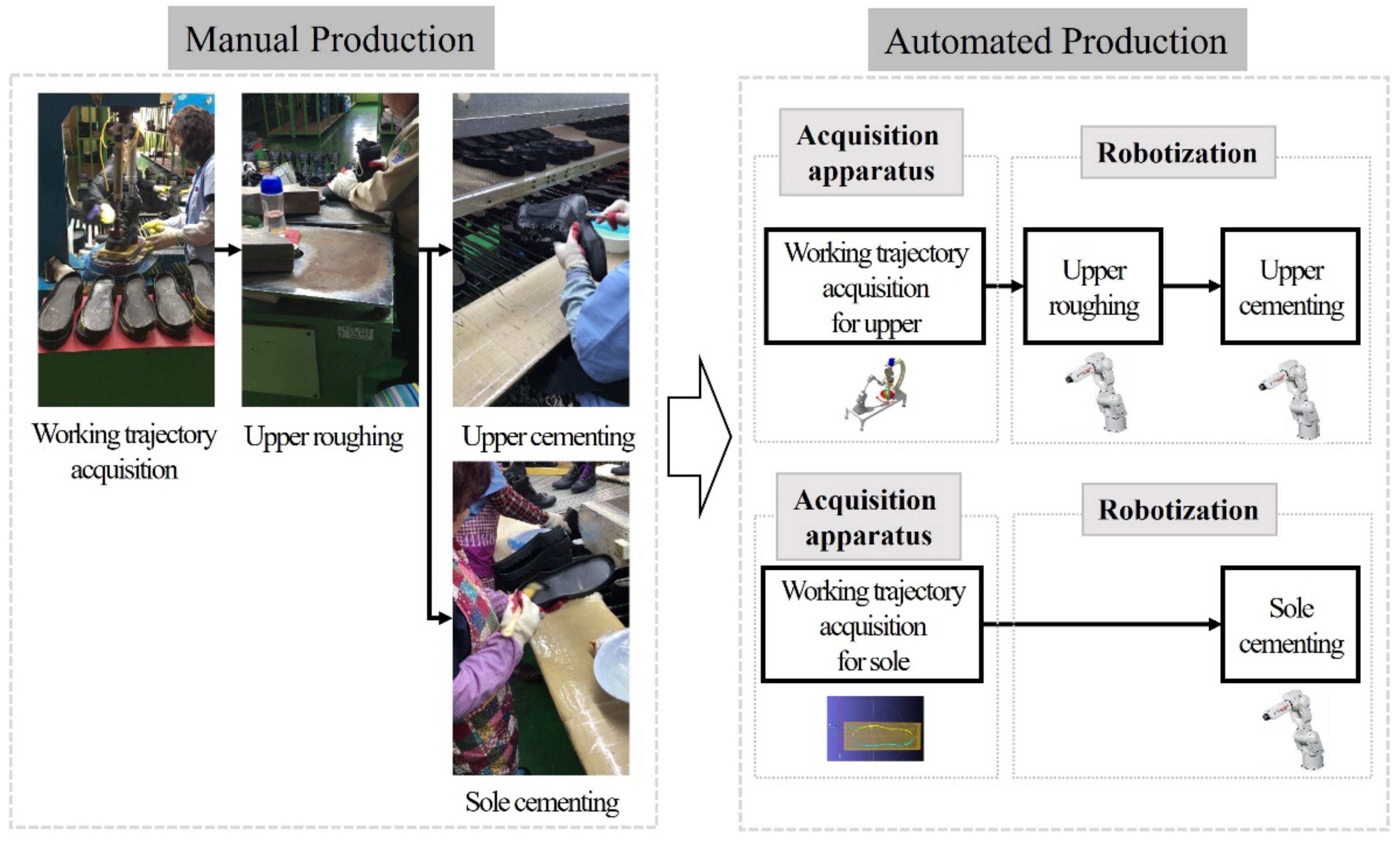
2. Upper Manufacturing Automation Process

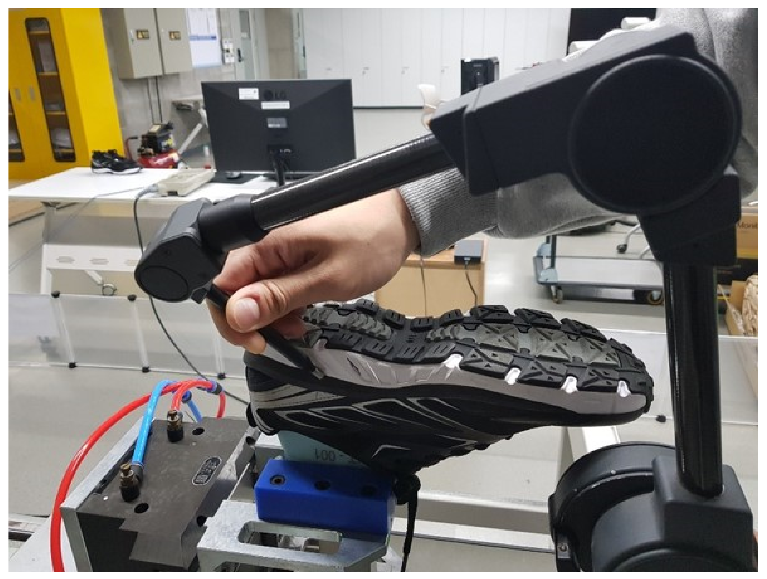
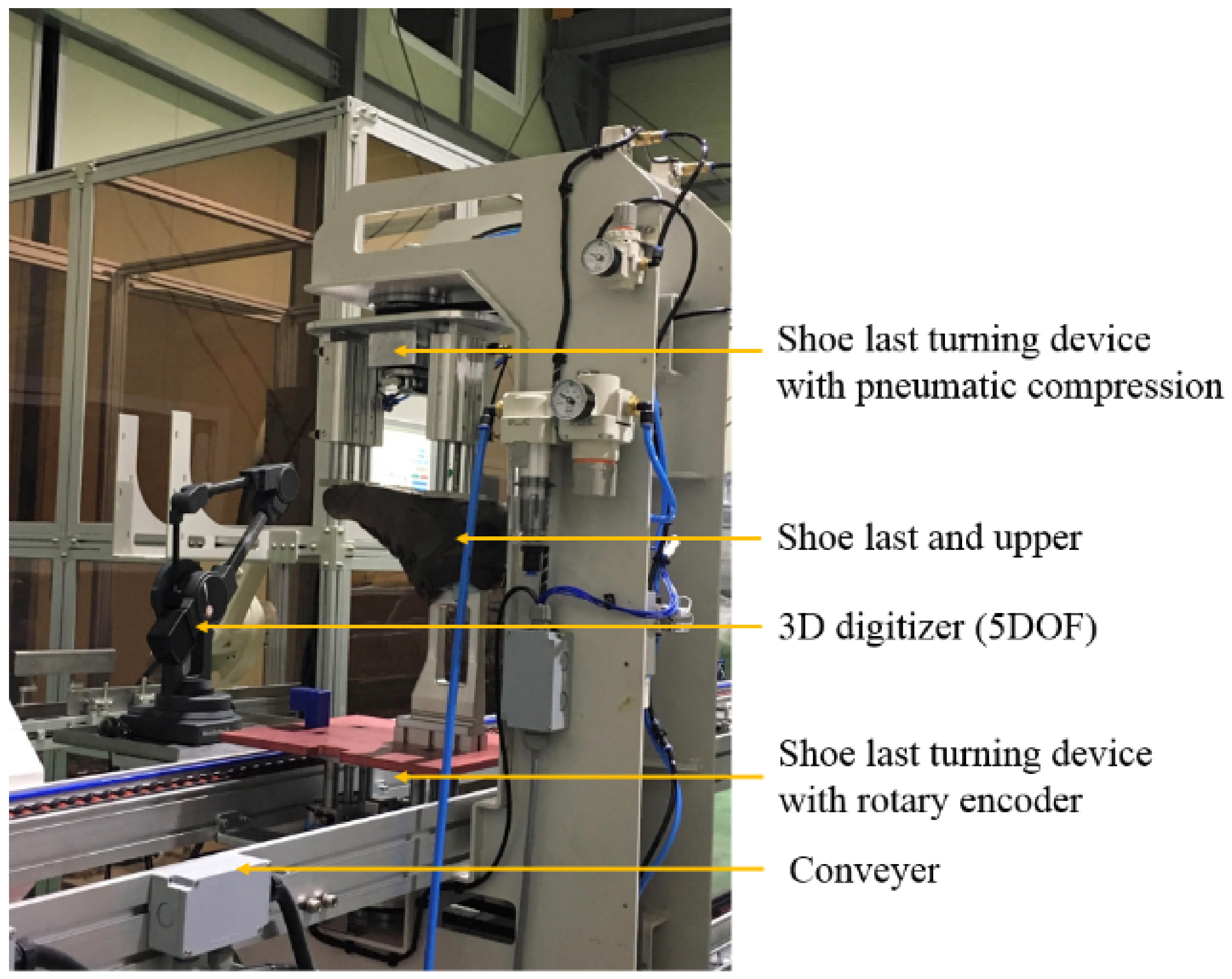
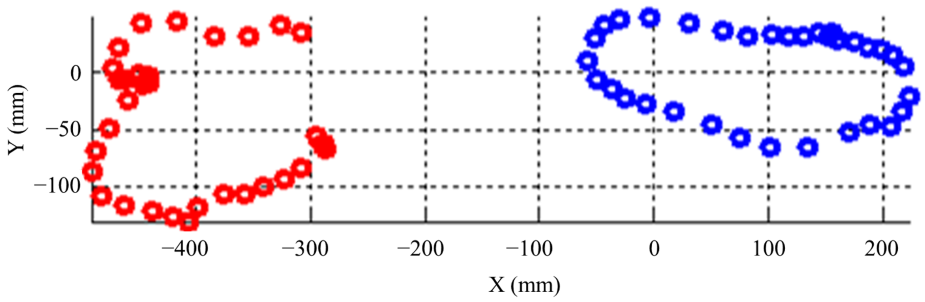
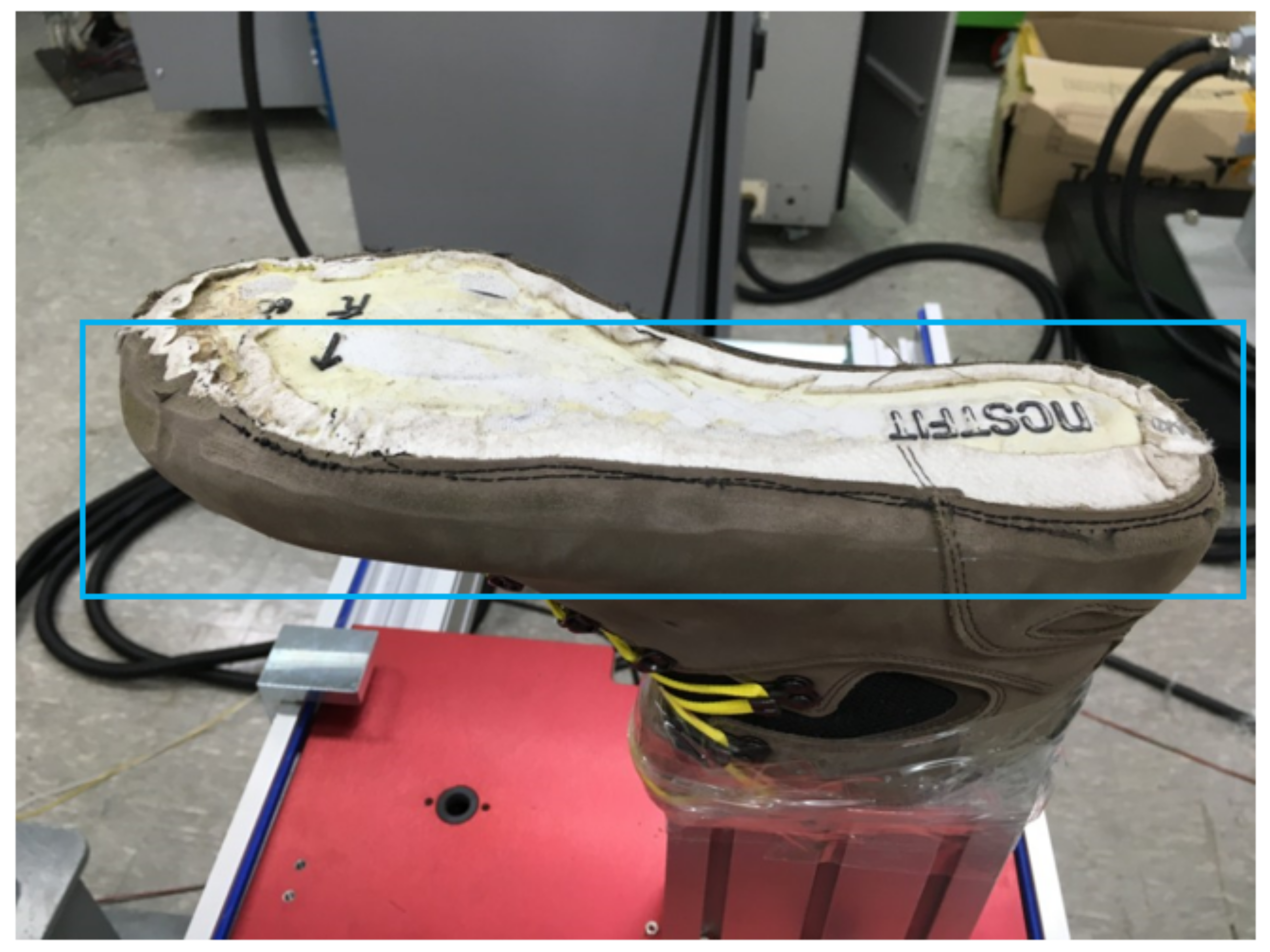
2.1. Task Path Acquisition System

It was necessary to generate a path and trajectory for the robot tool to be able to follow the surface of the object, which is a requirement for automating the roughing process. We proposed a task path acquisition system for measuring the upper gauge line. Figure 3 shows a conceptual design of the proposed task path acquisition system used in the upper manufacturing automation. The system consists of a digitizer, a shoe last turning device, a fixed jig, a pneumatic cylinder, and a sole fixing jig. The digitizer obtains the task path (i.e., gauge line) that is placed on the top and overlaps with the topline of the sole. The digitizer is Microscribe G2X model manufactured by RevWare Inc., and it has 0.23 mm of positional accuracy and 0.63 mm in reach [16]. Because the task path acquired by the digitizer has a distorted shape, an algorithm was developed for obtaining the form of the original shoe using the kinematic information of the digitizer and the rotational angle of the shoe’s last turning device.
The main feature of the proposed task path acquisition system is that it provides convenience and ease for the human worker when measuring the upper gauge line. Because the side surface of the closed curved surface is measured in several directions, as shown in Figure 4, it is difficult for workers to hold it by hand and make continuous contact with it. However, workers can do this by handling the digitizer with a slight arm movement while the shoe rotates automatically when the proposed system in Figure 3 is used.

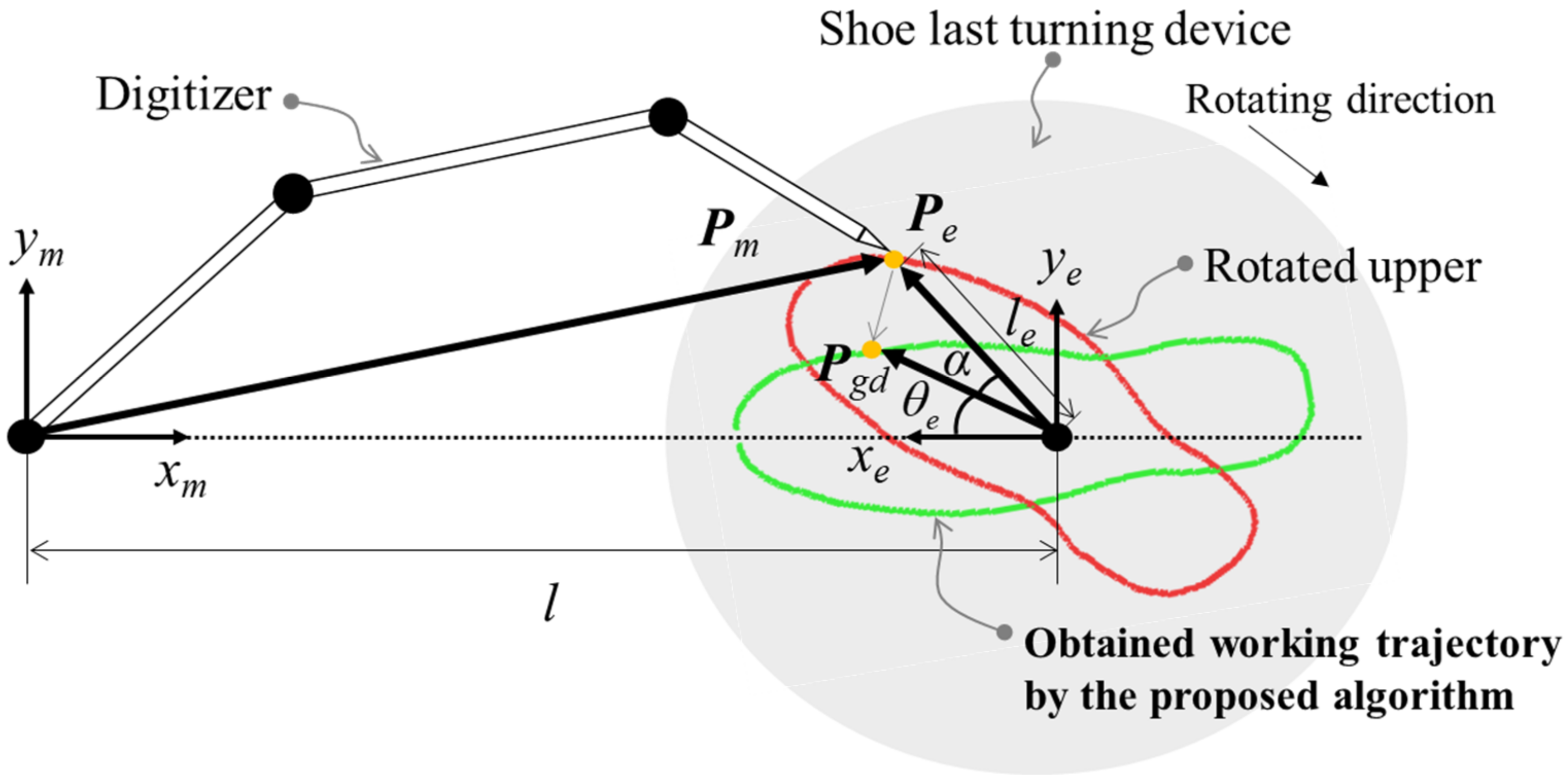
2.2. Task Path Acquisition Algorithm

The 3-D position placed on the upper part was measured using a combination of a 3-D digitizer and a shoe last-turning device, as shown in Figure 5. The position vector about the gauge line of the rotated upper Pe can be expressed as in Equation (1) in terms of Pm, which is a position vector measured by the digitizer, as depicted in Figure 5.
P e = x e y e z e = x m y m z m l 0 0
The length of the position vector Pe, le can be obtained using xe, which is calculated using the difference between the x-position of the digitizer tip xm and the distance l between the center of the digitizer and the center of the shoe last turning device, and ye, which is identical to ym. Hence, le can be described as follows:
l e = x e 2 + y e 2
The position vector of the topline of the rotated upper, Pe, can be represented in terms of le and θe by combining the shoe last turning device information with the digitizer information. That is,
P e = l e cos π θ e + α l e sin π θ e + α z m
where θe is the rotated angle of the shoe last measured by a rotary encoder installed in the shoe last turning device, and α is the angle between Pe and Pgd. The arctan2 function was used to determine α.
π θ e + α = a r c t a n 2 y e , x e
Hence,
α = π θ e a r c t a n 2 y e , x e
Using Equations (4) and (5), the task path on the upper side can be obtained as follows:
P g d = x g d y g d z g d = l e cos π α l e sin π α z m
Pgd is the resulting task path that is transformed into the robot coordinate system for the upper roughing and cementing tasks. Because Pgd represents positional information, as shown in Equation (6), it is essential to generate the orientation (i.e., roll, pitch, and yaw) of the robot end-effector before sending task commands to the robot. The details of how to create orientation information using only position information, Pgd, are described in Section 2.3.
The use of the shoe last turning device makes obtaining the upper gauge line more convenient and easier for human workers. Without the shoe last turning device, a human worker has to draw the gauge line around the upper end while the shoe last is fixed, which has two significant disadvantages. One is that a worker needs to move his/her arm through the entire perimeter of the upper arm; the other disadvantage is that it is not easy to consider whether the gauge line on the heel side of the upper arm, which is occluded from the human worker’s view, is properly set up by the digitizer.
These disadvantages were successfully overcome by adopting a rotating shoe last-turn device. With the proposed system, when a human worker acquires an upper task path, he or she can move the arm within a smaller range while holding the digitizer tip during the last rotation. This system also provides another benefit by enabling an examination of whether the gauge line is made correctly without obscuring the worker’s view.

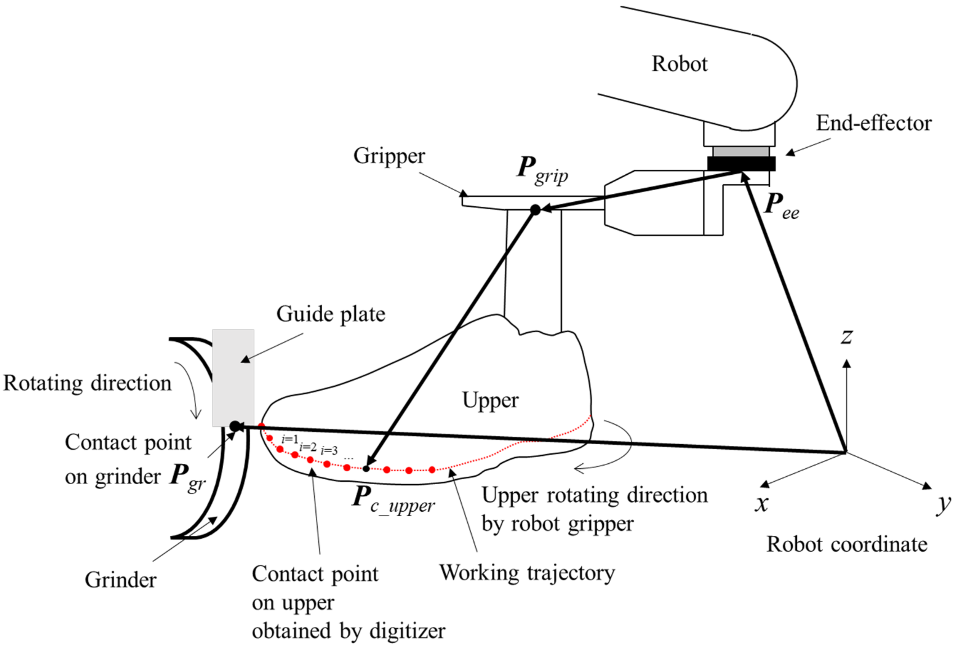
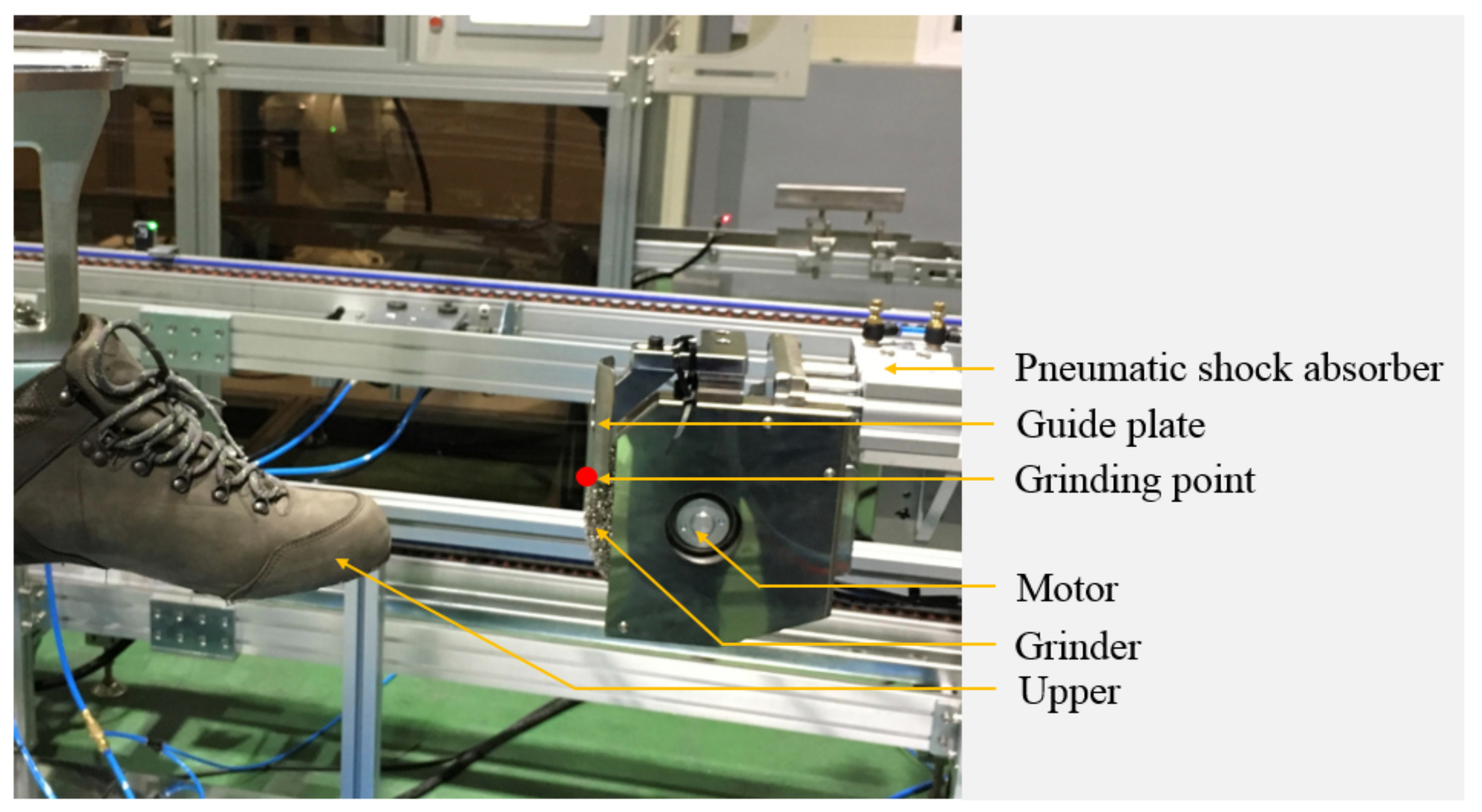
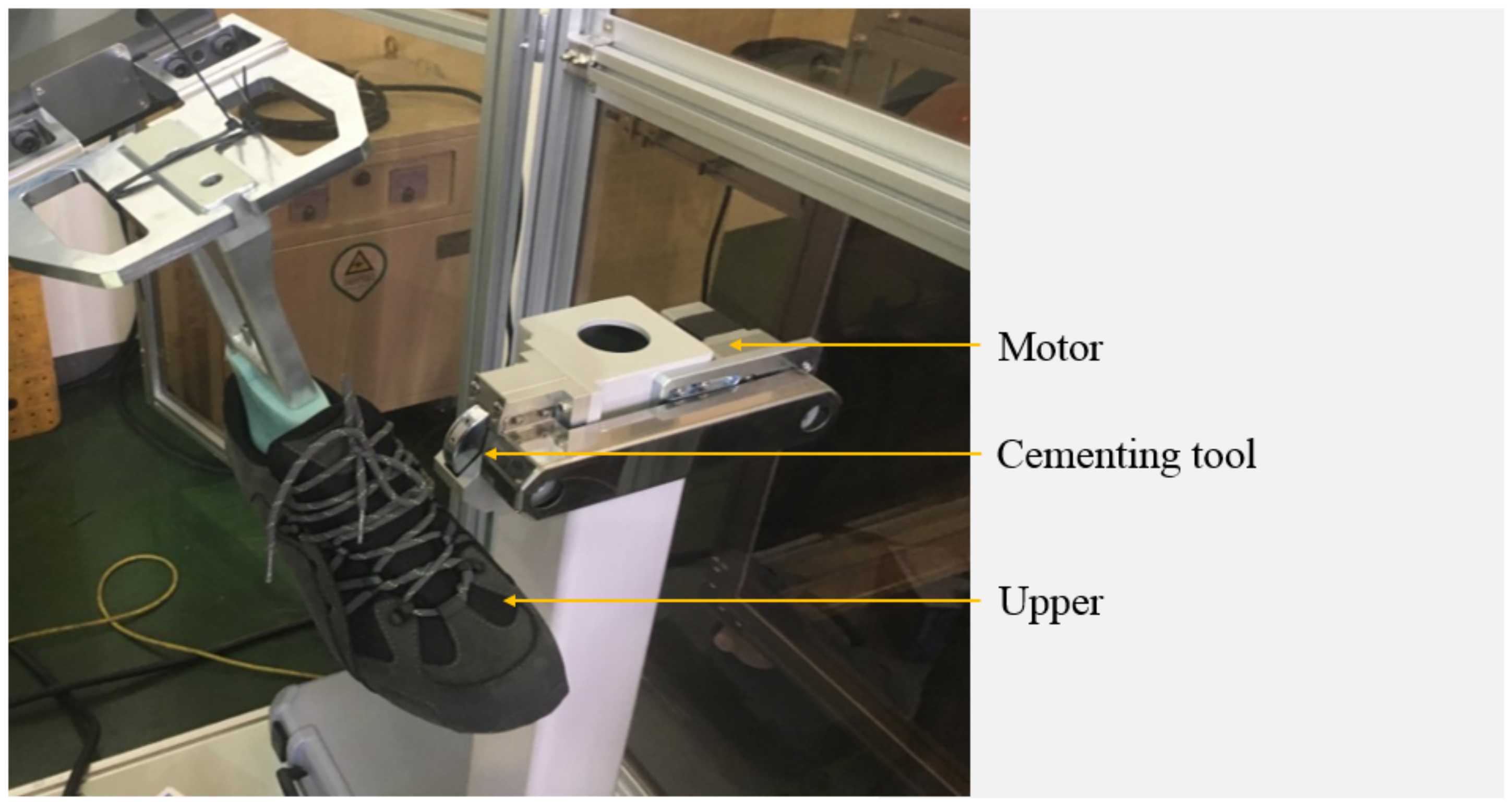
2.3. Robot Path Generation for Roughing and Cementing

The industrial robot performs the roughing and cementing of the upper part based on the path acquired by the proposed acquisition system. To achieve this, the task path in the coordinates of the shoe last turning device must be transformed into the robot coordinate system. Therefore, a robot path-generating algorithm for roughing and cementing is proposed in this section. Figure 6 shows the robot path generation process for upper roughing and cementing.
With the proposed algorithm, the points acquired by the digitizer in the coordinates of the last turning device of the shoe are transformed into points in the robot coordinate system. Given the position vector of the robot end-effector Pee, the position vector of grasping the shoe last by gripper Pgrip, and the position vector of the task path on the upper Pgd, the desired contact point of the upper with the tools Pc_upper in the robot coordinate system can be calculated by the following equation:
P c _ u p p e r = P e e + P g r i p + P g d
To obtain the robot path for contacting the upper part of the tool, the orientation of the robot must be calculated beforehand. The rotation matrix in the calculation of Rc was defined using the Z-Y-Z Euler angle.
R c = c O s O 0 s O c O 0 0 0 1 c A 0 s A 0 1 0 s A 0 c A c T s T 0 s T c T 0 0 0 1
where O, T, and A are the roll, pitch, and yaw of the robot end-effector, respectively. Here, A and T are fixed angles for the upper roughing and cementing, and they were experimentally obtained. O was calculated using the following equation:
O = o f f s e t + 360 ° a n
where a is the total number of measured points on the upper surface, n is the current point of the measurement for upper roughing and cementing, and the offset was obtained through experiments. Robot path Pc can be generated using the following equation:
P c = P g r R c P c _ u p p e r
where Pgr denotes the contact point on the grinder for roughing and cementing. Equations (9) and (10) suggest a computing algorithm for robot path generation based on the task path Pgd, which only contains position information.

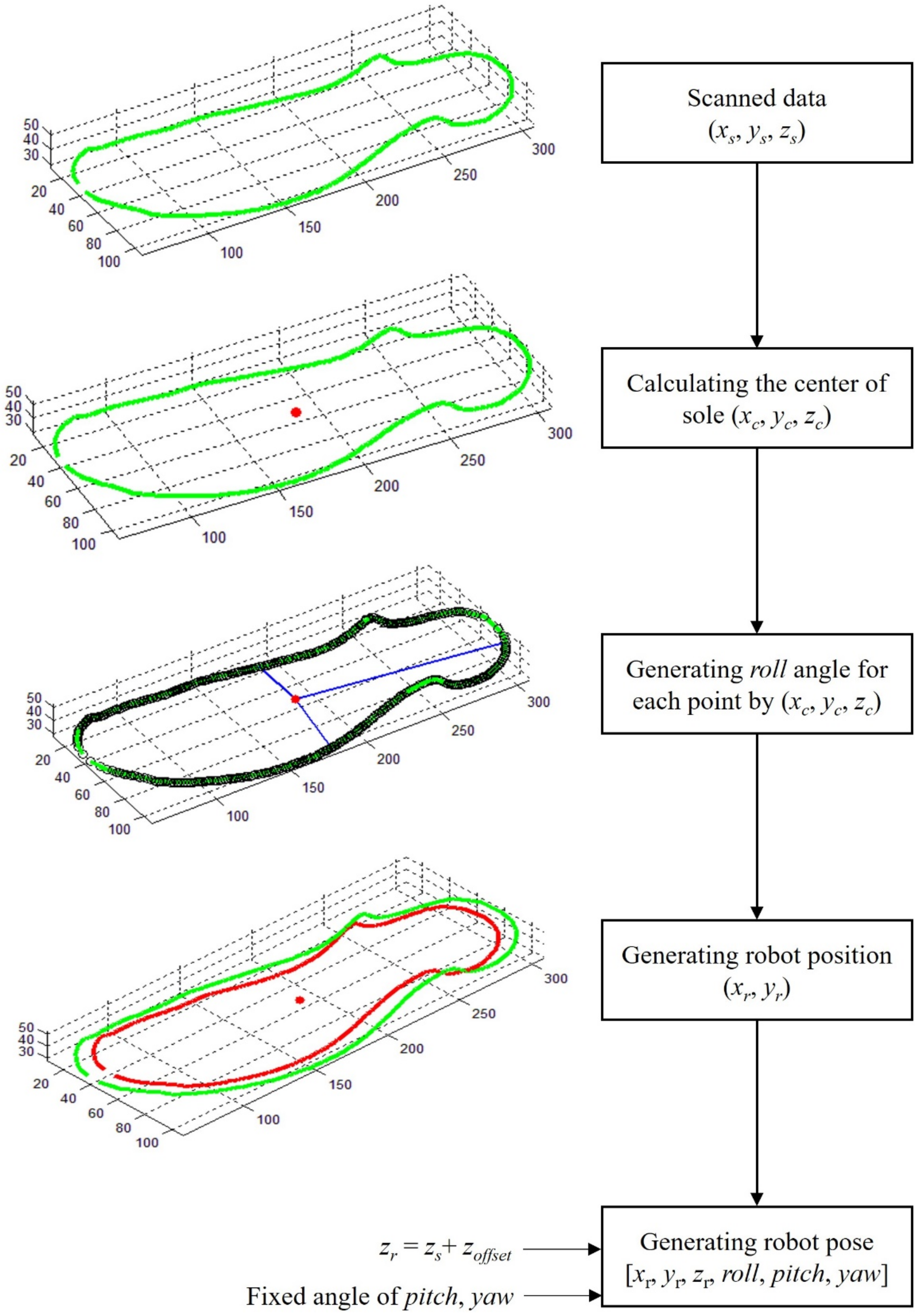
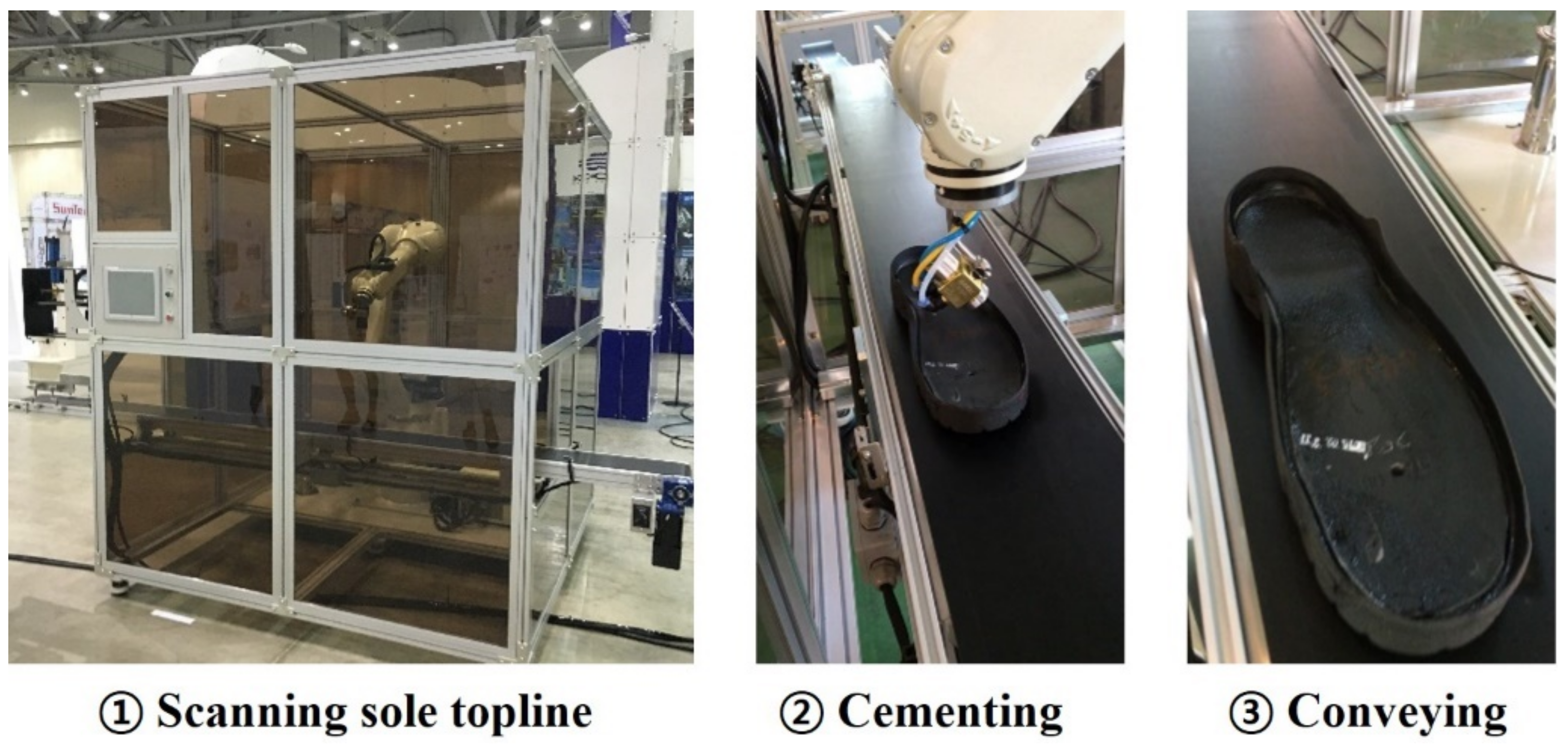
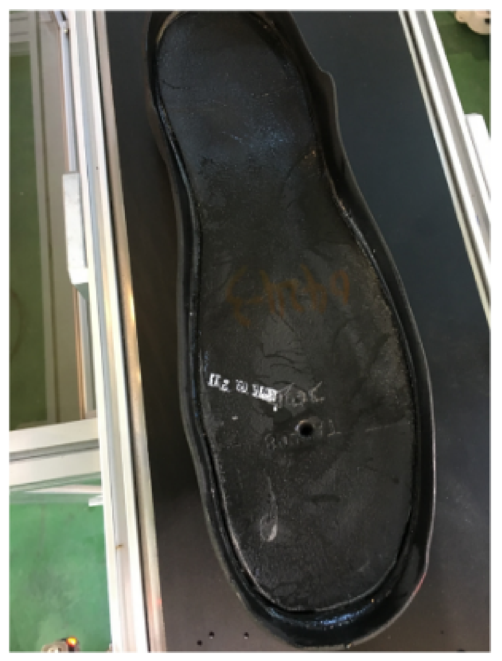
3. Sole Manufacturing Automation Process

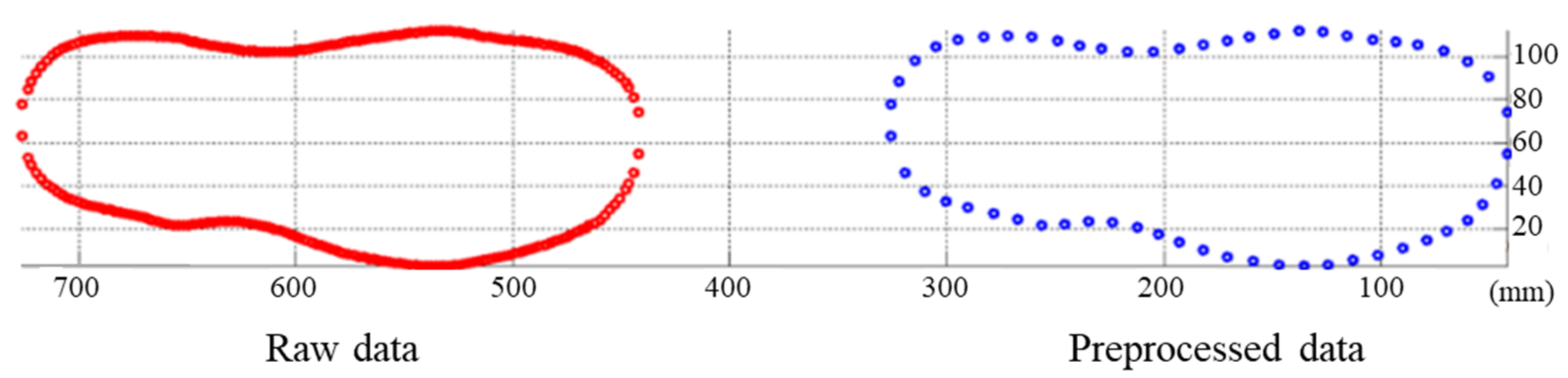
3.1. Preprocessing of 3-D Scanned Data for Sole

The 3-D scanned point data for the topline of the sole were used in the cementing process. The number of data points is approximately 400 points for the topline of the sole; however, it varies depending on the conveyor speed, color of the sole, lighting conditions, etc. Hence, the measured data must be preprocessed before being transformed into data for the robot coordinate system.
As shown in Figure 7, in the preprocessing algorithm, the number of raw data points, k, acquired from the 3-D scanner was first counted. Then, the algorithm set the initial point P1(xi, yi)i = 1, which is compared with the neighbor data points Pj(xj, yj) to determine whether norm d is satisfied. When the compared neighbor point meets the requirement, it is saved for use in generating the robot path.

3.2. Robot Path Generation for Cementing
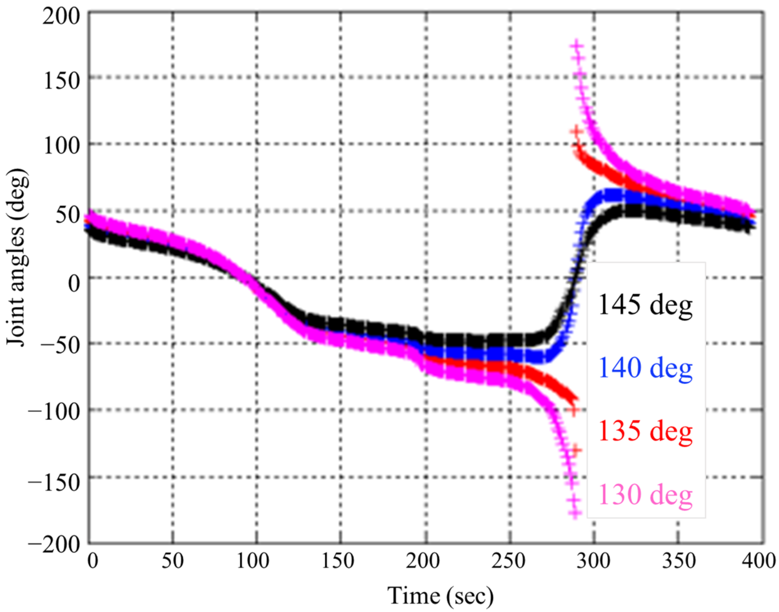
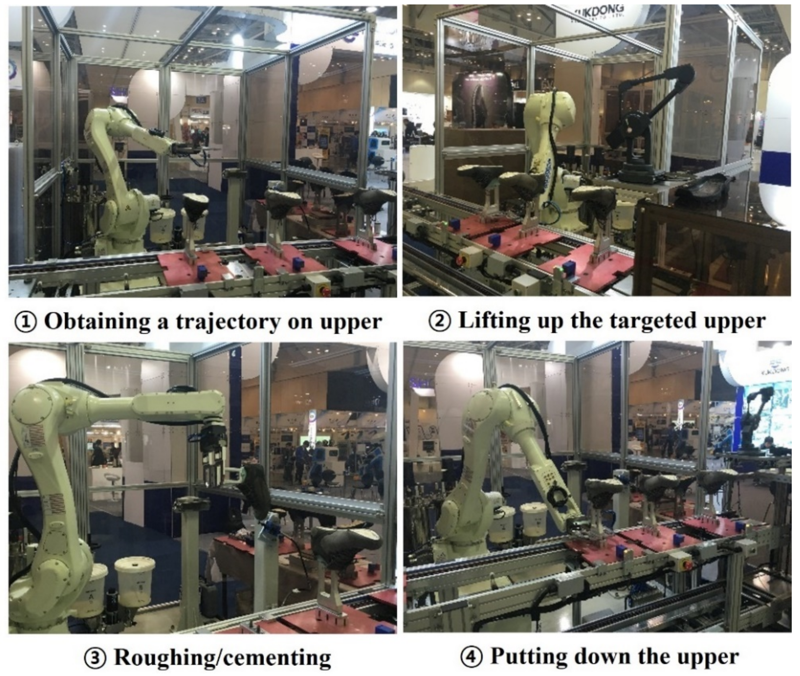
In the robot path generation for the sole cementing task, it is essential to consider insufficient information about the topline of the sole, which only has a 3-D position in the XYZ coordinate. To ensure that the robot performs the appropriate path for cementing the sole, an algorithm to generate the roll, pitch, and yaw of the robot end-effector is suggested, as shown in Figure 8. Using the scanned data xs, ys, and zs, the center positions of the sole xc, yc, and zc are calculated. Based on the center position of the sole, the roll angle of the robot end-effector for each obtained position was estimated. Next, the actual robot position for cementing xr and yr was generated within a certain distance (e.g., 25 mm) inside the topline. The final 6-D robot motion for cementing, xr, yr, zr, roll, pitch, and yaw, is calculated with fixed pitch and yaw angles considering the robot joint limitations.
For instance, with fixed angles, continuous robot motions can be generated when the pitch angle is set in the range of 140°–145°, as shown in Figure 9. When the pitch angle was set from 140° to 145°, the fourth and sixth joints of the robot were changed by 360°, which resulted in unnecessary robot motions during the cementing of the sole. The values of the fixed angles were set by considering the tool offset and the workspace inside the sole.
In order to implement the cementing process for the entire area of the sole, the robot should spray adhesive both onto the inner wall of the sole and onto bottom of the sole. Because the bottom of the sole has a relatively large area, the robot covers the entire surface by moving along two neighboring paths. Therefore, all three paths are necessary for the cementing wall and bottom of the sole. The sole cementing trajectory computing algorithm is enhanced by adding these additional paths as shown in Figure 10. This algorithm generates three robot paths for spraying the adhesive inside the entire area of the sole.
The robot paths for cementing the bottom of the sole were generated at a fixed distance of 25 mm between neighboring paths. The second and third paths were calculated with different fixed pitch angles of 150° and 120°, respectively, which were experimentally obtained.

4. Experiments

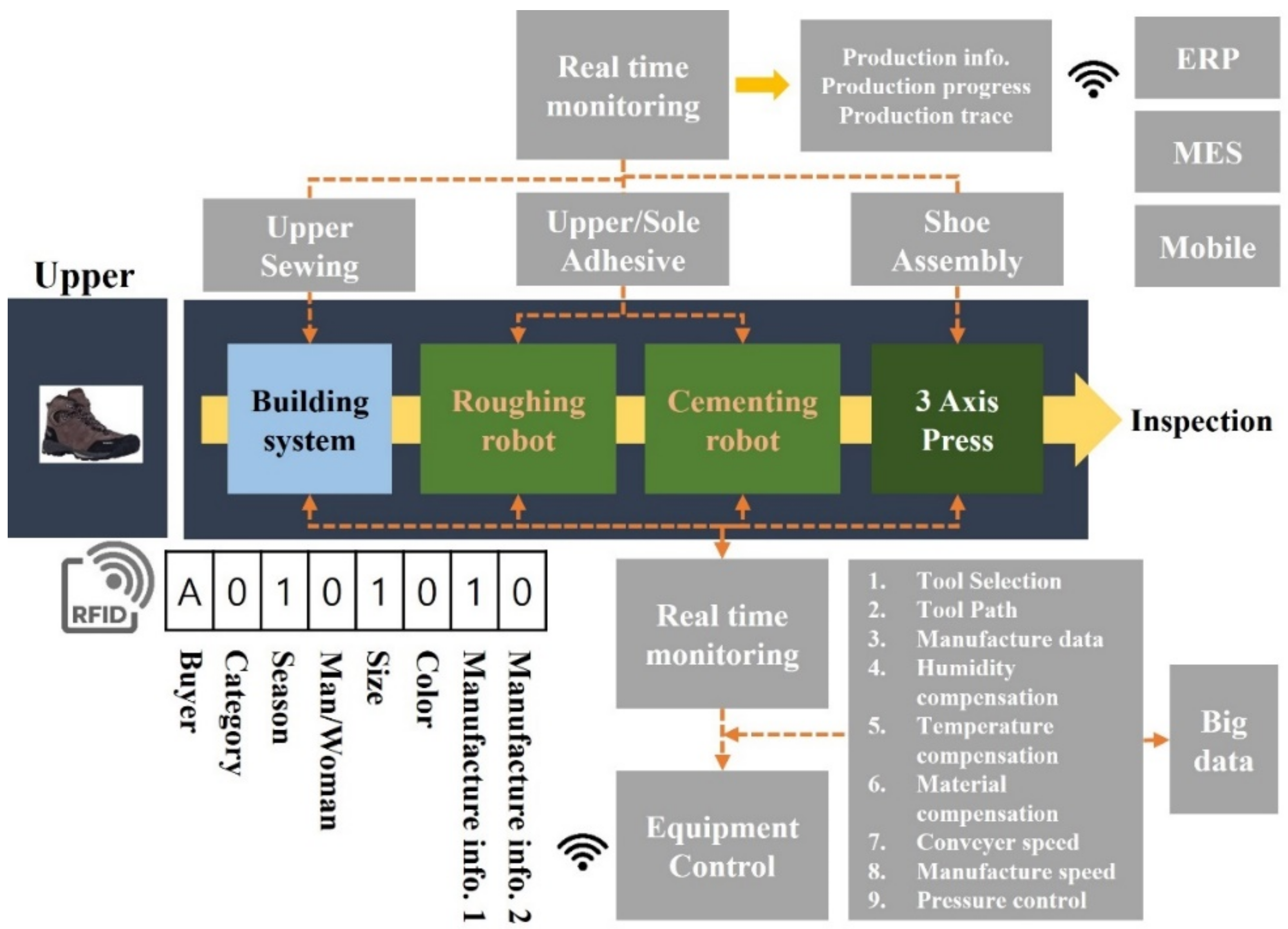
4.1. Robot-Based Automated Production Testbed

The concept of automation in shoe manufacturing is illustrated in Figure 11. The shoe manufacturing process consists of an upper building, upper roughing and cementing, sole cementing process, and a three-axis press for assembling the upper and sole. Shoe production is managed by RFID, and all manufacturing processes are monitored by sensors that accumulate big data. The experiments in this study focused on the roughing robot and cementing robot in Figure 11.
The automated production testbed for upper roughing, cementing, and sole cementing was designed, as shown in Figure 12 and Figure 13. A robot cell for upper roughing and cementing consists of four main components: an industrial robot, roughing/cementing tools for the upper, a 3-D digitizer, and a computer. An industrial robot, made by Kawasaki Robotics, Ltd. in Japan (Model: RS20NFE01), was used to pick up a target shoe from the conveyor and then perform the roughing and cementing tasks. Roughing and cementing tools were installed independently in the cell. The operation of the tools is initiated by an I/O logic controller signal that manages the entire manufacturing process of an assembly line.
Figure 14 shows the proposed task path acquisition system installed in the production testbed. It contains the shoe last turning device with a pneumatic compression, a rotary encoder, and a 3-D digitizer with 5-DOF.
In manufacturing automation, the industrial robot, cementing tool for the sole, 3-D scanner, and computer are the main components of the system. The same model of an industrial robot as used in the upper roughing and cementing tasks was deployed to perform cementing solely based on the XYZ data of the topline of the sole, as measured with the 3-D scanner. The computer converted the recognized XYZ topline data from the sole to the robot path. The cementing tool was installed in the end-effector of the robot, in contrast to for the upper roughing and cementing tasks.
Figure 15 shows an upper roughing tool, including a pneumatic shock absorber, guide plate, and grinder. The pneumatic shock absorber plays a role in properly transferring the reaction force created by the contact between the upper and the grinder. A guide plate that can be used when calculating the contact point, which is the grinding point between the upper and grinder, was designed.
As shown in Figure 16, the main components of the upper cementing tool contain an electric motor for rotating the cementing tool and a pumping device for the liquid adhesive. In Figure 17, a cementing tool for the sole, which is a spraying gun type manufactured by Sakai (Model: A-100), is installed in the robot end-effector. The quantity of the adhesive can be adjusted according to the injection pressure.

4.2. Results

The experiment was performed using one of the hiking shoes manufactured by Treksta, a shoe manufacturing company. Figure 18 shows the experimental results of the proposed algorithm using the task path acquisition system for the upper part. The red-colored data on the left in Figure 18 shows the raw data obtained using only the digitizer. The blue data points represent the trajectory estimated by the proposed algorithm. The results in Figure 18 confirm that the algorithm for calculating the shape of the upper using the proposed task path acquisition apparatus was properly designed.
As can be seen inside the blue box in Figure 19, the upper part is grounded based on the acquired task path in Figure 18. A professional engineer in the R&D department of Treksta examined the results of the robot roughing task and evaluated the roughing quality of the upper results. It was commented that the robot performed well while following the task path in general; however, it was further required for the robot to be able to grind evenly. In particular, as every shoe model produced by the shoe manufacturing company has a different required degree of roughing, a robot force control for the roughing tool might be needed. This request from the shoe manufacturing company remains for future work.
Figure 20 shows the resulting preprocessed data with an equal distance between points calculated using the algorithm. The preprocessing data were used for creating the 6-D motion of the robot for the sole cementing task.
The sole cementing result was verified with water injection through a cementing tool, and the same professional investigated the robot performance. The sole cementing was properly performed by the robot without water overflowing outside the sole wall, as shown in Figure 21. It was confirmed that the computing algorithms developed for sole cementing performed as designed.

5. Conclusions

In this paper, a new robot-based shoe manufacturing system for the upper and sole manufacturing processes was proposed, and its field applicability was demonstrated through a testbed. For the upper manufacturing process, a task path acquisition device that allows for an operator to easily obtain a task path (e.g., a gauge line) was proposed. An algorithm was proposed that converts positional path information into 6-DOF robot motion by considering the roughing and cementing tool information from the obtained task path; through this, the robot path was generated. Compared to the non-contact method using a complicated system with 3-D vision, XRF spectrometer, and manipulator in [15], the contact method using the proposed task path acquisition system for the upper manufacturing process was simple and inexpensive. The disadvantage was that a worker is required to operate the task path acquisition device. However, the operator’s convenience was increased by utilizing the proposed task path acquisition system. For the sole manufacturing process, the path data were extracted through preprocessing of the 3-D scanned sole path data, and a robot path calculation algorithm for adapting the outer and inner soles was proposed. All performances were verified through experiments on a demonstration production line in a real shoe-manufacturing company factory. When comparing the time between the manual work by a human worker and the robot-based manufacturing for the sole manufacturing process, the processing time for a skilled worker was about 10 sec for spraying one sole, which was similar when a robot-based cementing was applied. Although the operation time was similar, it is an important contribution that the human operator is not required for sole manufacturing in a hazardous environment using adhesives as in this proposed approach using a robot.
Although the proposed system has been verified, additional consideration is required for continuous field applications in the near future. For full automation, research on how to automatically extract accurate gauge lines using low-cost sensors instead of a contact method or complicated non-contact method is required for upper manufacturing. For sole manufacturing, further research to determine the optimal tool orientation according to the shape of the sole and to plan a smooth trajectory for accuracy are also needed. The comparison with another commercial system, such as in [2], is necessary. In addition, it is necessary to improve the quality of the surface-roughing operation by applying force control in order to evenly grind the upper surface.

Author Contributions

Conceptualization, M.J. and M.J.H.; Methodology, M.-G.K., J.K., S.Y.C. and M.J.H.; Data Curation, M.-G.K., J.K. and S.Y.C.; Software, M.-G.K., J.K. and S.Y.C.; Experiments, M.-G.K., J.K. and M.J.; Analysis, M.-G.K., J.K., M.J. and M.J.H.; Writing—Original Draft and Revision, M.-G.K., J.K., S.Y.C., M.J. and M.J.H.; Supervision, M.J. and M.J.H.; Funding Acquisition, M.J. and M.J.H. All authors have read and agreed to the published version of the manuscript.

Funding

This work was supported by the 2021 Research Fund of the University of Seoul for Myun Joong Hwang. And, this work was also supported by the Ministry of Trade, Industry and Energy (MOTIE, Korea) under the Industrial Technology Innovation Program (Development of sole manufacturing and assembly system for smart shoe factory) under Grant 20001593 for KIRO (Korea Institute of Robotics & Technology Convergence).

Acknowledgments

The authors would like to thank Kukdong Corp. for providing conveyor lines and tools. In addition, 4D Culture developed the 3D scan system for their intensive cooperation with us during this research project. We would also like to thank Treksta, who offered their products and provided valuable advice and comments on the experiments.

Conflicts of Interest

The authors declare no conflict of interest.

References

  1. Chen, B.; Wan, J.; Shu, L.; Li, P.; Mukherjee, M.; Yin, B. Smart Factory of Industry 4.0: Key Technologies, Application Case and Challenges. IEEE Access 2018, 6, 6505–6519. [Google Scholar] [CrossRef]
  2. ORISOL, Automatic Robotic Cementing System. Available online: https://orisol.com/assembly-solutions (accessed on 19 March 2022).
  3. Ding, Y.; Zhao, J.; Goonetilleke, R.S.; Xiong, S.; Yuan, Z.; Zhang, Y.; Long, C. An Automatic Method of Measuring Foot Girths for Custom Footwear Using Local RBF Implicit Surfaces. Int. J. Comput. Integr. Manuf. 2010, 23, 574–583. [Google Scholar] [CrossRef]
  4. Molinari-Tosatti, L.; Fassi, I. Parallel Kinematic Machines for An Application in Shoes Manufacturing: The Conceptual Design to The First Experimental Campaign. In Proceedings of the IEEE/RSJ International Conference on Intelligent Robots and Systems (IROS), Maui, HI, USA, 29 October–3 November 2001; pp. 433–438. [Google Scholar] [CrossRef]
  5. Hu, Z.; Marshall, C.; Bicker, R.; Taylor, P. Automatic Surface Roughing with 3D Machine Vision and Cooperative Robot Control. Robot. Auton. Syst. 2007, 55, 552–560. [Google Scholar] [CrossRef]
  6. Nemec, B.; Leon, Z. Shoe Grinding Cell using Virtual Mechanism Approach. In Proceedings of the 5th International Conference on Informatics in Control, Automation and Robotics (ICINCO-RA), Madeira, Portugal, 11–15 May 2008; pp. 159–164. [Google Scholar] [CrossRef] [Green Version]
  7. Pedrocchi, N.; Villagrossi, E.; Cenati, C.; Tosatti, L.M. Design of Fuzzy Logic Controller of Industrial Robot for Roughing the Uppers of Fashion Shoes. Int. J. Adv. Manuf. Technol. 2015, 77, 939–953. [Google Scholar] [CrossRef]
  8. Gracia, L.; Perez-Vidal, C.; Mronga, D.; de Paco, J.M.; Azorin, J.M.; de Gea, J. Robotic Manipulation for The Shoe-Packaging Process. Int. J. Adv. Manuf. Technol. 2017, 92, 1053–1067. [Google Scholar] [CrossRef]
  9. Perez-Vidal, C.; Gracia, L.; de Paco, J.M.; de Gea, J. Automation of Product Packaging for Industrial Applications. Int. J. Comput. Integr. Manuf. 2017, 31, 129–137. [Google Scholar] [CrossRef]
  10. Castelli, K.; Zaki, A.M.A.; Dmytriyev, Y.; Carnevale, M.; Giberti, H. A Feasibility Study of a Robotic Approach for the Gluing Process in the Footwear Industry. Robotics 2021, 10, 6. [Google Scholar] [CrossRef]
  11. Kim, J.Y. CAD-Based Automated Robot Programming in Adhesive Spray Systems for Shoe Outsoles and Uppers. J. Robot. Syst. 2004, 21, 625–634. [Google Scholar] [CrossRef]
  12. Oliver, G.; Gil, P.; Gomez, J.F.; Torres, F. Towards Footwear Manufacturing 4.0: Shoe Sole Robotic Grasping in Assembling Operations. Int. J. Adv. Manuf. Technol. 2021, 114, 811–827. [Google Scholar] [CrossRef]
  13. Oliver, G.; Gil, P.; Torres, F. Robotic Workcell for Sole Grasping in Footware Manufacturing. In Proceedings of the 25th IEEE International Conference on Emerging Technologies and Factory Automation (ETFA), Vienna, Austria, 8–11 September 2020; pp. 704–710. [Google Scholar]
  14. Kim, M.G.; Kim, J.; Shin, D.; Jin, M. Robot-based Shoe Manufacturing System. In Proceedings of the 18th International Conference on Control, Automation and Systems (ICCAS), YongPyong, Korea, 17–20 October 2018; p. 1491. [Google Scholar]
  15. Mai, C.C.; Huang, C.K.; HoCheng, H. Three-Dimensional Trajectory Recognition Technology for the Junction Trace of a Material Assembly Used in footwear manufacturing Automation. In Proceedings of the 20th International Conference on Advanced Robotics (ICAR), Ljubljana, Slovenia, 6–10 December 2021; pp. 38–43. [Google Scholar] [CrossRef]
  16. Summit Technology Group, MicroScribe G2X. Available online: http://www.stg-inc.com/microscribe.shtm (accessed on 19 March 2022).
Figure 1. Photos of the manual process of drawing a gauge line with a pen, roughing, and gluing.
Machines 10 00255 g001
Figure 2. Overall process of proposed robot-based automation for upper and sole manufacturing.
Machines 10 00255 g002
Figure 3. Task path acquisition system in upper manufacturing.
Machines 10 00255 g003
Figure 4. Measurement process in a fixed shoe using the digitizer.
Machines 10 00255 g004
Figure 5. Coordinate system for calculating the task path on the upper.
Machines 10 00255 g005
Figure 6. Concept of robot path generation process for upper.
Machines 10 00255 g006
Figure 7. Preprocessing algorithm for 3-D scanned topline of sole.
Machines 10 00255 g007
Figure 8. Robot path generation algorithm for cementing near topline.
Machines 10 00255 g008
Figure 9. Trajectory of fourth joint angle when pitch angle is fixed between the range of 130° and 145°.
Machines 10 00255 g009
Figure 10. Robot path generation algorithm for cementing wall and inner bottom of the sole.
Machines 10 00255 g010
Figure 11. Schematic diagram of a robot-based shoe manufacturing automation system.
Machines 10 00255 g011
Figure 12. Proposed robot-based upper manufacturing process.
Machines 10 00255 g012
Figure 13. Proposed robot-based sole manufacturing process.
Machines 10 00255 g013
Figure 14. Proposed task path acquisition system installed in the testbed.
Machines 10 00255 g014
Figure 15. Roughing tool for upper.
Machines 10 00255 g015
Figure 16. Cementing tool for upper.
Machines 10 00255 g016
Figure 17. Cementing tool for sole.
Machines 10 00255 g017
Figure 18. Experimental result of the task path calculated by using the proposed task path acquisition system and algorithm (Left: path based on raw data, Right: transformed path).
Machines 10 00255 g018
Figure 19. Roughing result for upper.
Machines 10 00255 g019
Figure 20. Result of the task path measured using the 3-D scanned data, which was then preprocessed to extract points with equal distance.
Machines 10 00255 g020
Figure 21. Cementing result for sole.
Machines 10 00255 g021
Publisher’s Note: MDPI stays neutral with regard to jurisdictional claims in published maps and institutional affiliations.

